US5148159A - Remote control system with teach/learn setting of identification code - Google Patents
Remote control system with teach/learn setting of identification codeDownload PDFInfo
- Publication number
- US5148159A US5148159AUS07/343,921US34392189AUS5148159AUS 5148159 AUS5148159 AUS 5148159AUS 34392189 AUS34392189 AUS 34392189AUS 5148159 AUS5148159 AUS 5148159A
- Authority
- US
- United States
- Prior art keywords
- identification code
- memory
- radio frequency
- base unit
- asynchronous communications
- Prior art date
- Legal status (The legal status is an assumption and is not a legal conclusion. Google has not performed a legal analysis and makes no representation as to the accuracy of the status listed.)
- Expired - Fee Related
Links
Images


Classifications
- G—PHYSICS
- G08—SIGNALLING
- G08C—TRANSMISSION SYSTEMS FOR MEASURED VALUES, CONTROL OR SIMILAR SIGNALS
- G08C19/00—Electric signal transmission systems
- G08C19/16—Electric signal transmission systems in which transmission is by pulses
- G08C19/28—Electric signal transmission systems in which transmission is by pulses using pulse code
- G—PHYSICS
- G07—CHECKING-DEVICES
- G07C—TIME OR ATTENDANCE REGISTERS; REGISTERING OR INDICATING THE WORKING OF MACHINES; GENERATING RANDOM NUMBERS; VOTING OR LOTTERY APPARATUS; ARRANGEMENTS, SYSTEMS OR APPARATUS FOR CHECKING NOT PROVIDED FOR ELSEWHERE
- G07C9/00—Individual registration on entry or exit
- G07C9/00174—Electronically operated locks; Circuits therefor; Nonmechanical keys therefor, e.g. passive or active electrical keys or other data carriers without mechanical keys
- G07C9/00182—Electronically operated locks; Circuits therefor; Nonmechanical keys therefor, e.g. passive or active electrical keys or other data carriers without mechanical keys operated with unidirectional data transmission between data carrier and locks
- G—PHYSICS
- G07—CHECKING-DEVICES
- G07C—TIME OR ATTENDANCE REGISTERS; REGISTERING OR INDICATING THE WORKING OF MACHINES; GENERATING RANDOM NUMBERS; VOTING OR LOTTERY APPARATUS; ARRANGEMENTS, SYSTEMS OR APPARATUS FOR CHECKING NOT PROVIDED FOR ELSEWHERE
- G07C9/00—Individual registration on entry or exit
- G07C9/00174—Electronically operated locks; Circuits therefor; Nonmechanical keys therefor, e.g. passive or active electrical keys or other data carriers without mechanical keys
- G07C9/00857—Electronically operated locks; Circuits therefor; Nonmechanical keys therefor, e.g. passive or active electrical keys or other data carriers without mechanical keys where the code of the data carrier can be programmed
- G—PHYSICS
- G07—CHECKING-DEVICES
- G07C—TIME OR ATTENDANCE REGISTERS; REGISTERING OR INDICATING THE WORKING OF MACHINES; GENERATING RANDOM NUMBERS; VOTING OR LOTTERY APPARATUS; ARRANGEMENTS, SYSTEMS OR APPARATUS FOR CHECKING NOT PROVIDED FOR ELSEWHERE
- G07C9/00—Individual registration on entry or exit
- G07C9/00174—Electronically operated locks; Circuits therefor; Nonmechanical keys therefor, e.g. passive or active electrical keys or other data carriers without mechanical keys
- G07C2009/00753—Electronically operated locks; Circuits therefor; Nonmechanical keys therefor, e.g. passive or active electrical keys or other data carriers without mechanical keys operated by active electrical keys
- G07C2009/00769—Electronically operated locks; Circuits therefor; Nonmechanical keys therefor, e.g. passive or active electrical keys or other data carriers without mechanical keys operated by active electrical keys with data transmission performed by wireless means
- G07C2009/00793—Electronically operated locks; Circuits therefor; Nonmechanical keys therefor, e.g. passive or active electrical keys or other data carriers without mechanical keys operated by active electrical keys with data transmission performed by wireless means by Hertzian waves
- G—PHYSICS
- G07—CHECKING-DEVICES
- G07C—TIME OR ATTENDANCE REGISTERS; REGISTERING OR INDICATING THE WORKING OF MACHINES; GENERATING RANDOM NUMBERS; VOTING OR LOTTERY APPARATUS; ARRANGEMENTS, SYSTEMS OR APPARATUS FOR CHECKING NOT PROVIDED FOR ELSEWHERE
- G07C9/00—Individual registration on entry or exit
- G07C9/00174—Electronically operated locks; Circuits therefor; Nonmechanical keys therefor, e.g. passive or active electrical keys or other data carriers without mechanical keys
- G07C9/00857—Electronically operated locks; Circuits therefor; Nonmechanical keys therefor, e.g. passive or active electrical keys or other data carriers without mechanical keys where the code of the data carrier can be programmed
- G07C2009/00873—Electronically operated locks; Circuits therefor; Nonmechanical keys therefor, e.g. passive or active electrical keys or other data carriers without mechanical keys where the code of the data carrier can be programmed by code input from the lock
- G—PHYSICS
- G07—CHECKING-DEVICES
- G07C—TIME OR ATTENDANCE REGISTERS; REGISTERING OR INDICATING THE WORKING OF MACHINES; GENERATING RANDOM NUMBERS; VOTING OR LOTTERY APPARATUS; ARRANGEMENTS, SYSTEMS OR APPARATUS FOR CHECKING NOT PROVIDED FOR ELSEWHERE
- G07C9/00—Individual registration on entry or exit
- G07C9/00174—Electronically operated locks; Circuits therefor; Nonmechanical keys therefor, e.g. passive or active electrical keys or other data carriers without mechanical keys
- G07C9/00896—Electronically operated locks; Circuits therefor; Nonmechanical keys therefor, e.g. passive or active electrical keys or other data carriers without mechanical keys specially adapted for particular uses
- G07C2009/00928—Electronically operated locks; Circuits therefor; Nonmechanical keys therefor, e.g. passive or active electrical keys or other data carriers without mechanical keys specially adapted for particular uses for garage doors
Definitions
- the present inventionis in the field of remote control systems having security codes, and in particular such remote control systems such as used in garage door operators having a manner for specification of the security code employed.
- Remote control systems for control of gates or garage door operatorsare known in the art. These systems ordinarily employ a security code.
- each remote portable unit and each base unithas an operator specified security code.
- Each portable unitis capable of transmitting a signal encoded with the particular security code set therein.
- each base unitis responsive only to signals including a security code corresponding to the security code set in that base unit.
- a particular portable unit and base unit which are to be used togethermust have the same security code.
- This presence of a security codepermits more than one remote control system employing the same radio frequency to be used in the same neighborhood.
- it is possible to permit a relatively large number of security codesthereby greatly decreasing the likelihood that another portable unit by the same manufacturer would unintentionally operate a particular base unit.
- thisreduces the possibility of unauthorized entry by persons having knowledge of a particular manufacturer's technical characteristics.
- both the portable unit and in the base unitmust be match in order to support these security goals. It is known in the prior art to construct both the portable unit and the base unit having security codes which are operator selectable or operator alterable. In a typical remote control system of this type both the portable unit and the base unit would have their security codes set by a bank of switches. Such switches are typically embodied in miniature form in a dual in line package which is mounted on a circuit board in both the portable unit and in the base unit. A particular code is specified digitally depending upon the switch state of these switches. Selection of a particular security code involves the operator switching the bank of switches in both the portable unit and in the base unit to the same pattern, thereby specifying the same security code in each unit.
- Such remote control systemsare typically sold in packages including one or more portable units and a single base unit.
- each of the portable units and for the base unitis typical for each of the portable units and for the base unit to be set to a single factory preset code when first delivered to the purchaser. In this manner the system can be thoroughly tested to determine that it operates properly prior to the user selecting the particular security code to be used in his installation.
- a further security difficultyresults from the employment of this system for setting the security code. Because the security code can be visually read from the position of the switch bank, such a code is susceptible to unauthorized reading. Any person who has momentary access to one of the portable units can view this switch bank and determine the security code for that portable unit and the corresponding base unit. Because the typical use of such remote control systems is for garage door operators, the portable units are ordinarily stored in an automobile. Thus, anyone have momentary access to the automobile may be able to determine the particular security code of the garage where that automobile is ordinarily stored. Thus, for example, unscrupulous automobile repair facilities or service stations may use this method for entry for theft.
- Such a systemshould have a relatively easy manner for setting the security code in both the base and in the portable units.
- a remote control systemshould have a portable unit whose security code cannot be easily determined.
- the present inventionis remote control system including one or more portable units and a base unit.
- Each portable unitincludes at least one control input and corresponding identification code memories.
- the control inputsare manual momentary contact control push buttons.
- the portable unitUpon receipt of a particular control input, the portable unit transmits a radio frequency signal modulated by an identification code recalled from the identification code memory corresponding to the control input.
- the base unitlikewise has an identification code memory for storing a particular identification code.
- the base unitpreferably also includes some manner permitting the user to specify the particular identification code.
- the base unitincludes a radio frequency receiver set to receive the radio frequency signal transmitted by the portable units.
- the base unitcompares the identification code modulated on the received radio frequency signal with the identification code stored in the base unit identification code memory.
- the base unitperforms a function, such as control of a garage door, only if the received radio frequency signal is encoded with an identification code which is identical to the identification code stored in the base unit.
- Each of the portable unitsfurther includes an asynchronous communication port which mates with a similar asynchronous communication port in the base unit.
- the identification code for the systemis selected as follows.
- the base unit and a particular portable unitare connected together via the mating asynchronous communication ports.
- the base unittransmits data to the portable unit via the mating asynchronous communication ports corresponding to the particular identification code to which it is responsive.
- This dataenables the portable unit to store the identification code in a particular identification code memory within the portable unit.
- the portable unitpreferably includes a plurality of such identification code memories.
- the memory employed for storing the identification code received from the base unitcorresponds to one of the control inputs, preferably a control input activated during the teach/learn process. Thereafter the portable unit and base unit are separated.
- the identification code for the base unitmay be preset upon manufacture or it may be operator selectable or operator alterable.
- the manner of selecting the identification code for the base unitis relatively easy for the operator.
- the base identification codeis randomly set depending upon depression of a single push button at the base unit. Depression of this push button at the base unit starts a counter which is stopped upon release of this push button. The current count in the counter at this time specifies at least a portion of the base identification code.
- a second portion of the identification codeis set by the time within a repetitive time cycle that the push button is released.
- this base identification codeis stored with an electronic memory, of the type known as an electrically erasable programmable read only memory. The particular identification code is thus not susceptible to determination by visual inspection of the base unit.
- each portable unitincludes a capacitor for storing energy so that the battery, which ordinarily supplies electrical power to the portable unit, can be replaced without loss of power to the static random access memory and therefore without loss of the identification code stored therein.
- each portable unitincludes a plurality of control push buttons, such as four, for entry of the control inputs and further includes corresponding identification code memories.
- a single portable unitcan be taught the identification codes of multiple base units. This permits a single portable unit to operate a plurality of base units. This may also enable a single portable unit to control a plurality of operations of a single base unit.
- a further aspect of the present inventioninvolves the use of a factory preset code.
- the operatoris able to reset each of the identification codes within each portable unit and/or the identification code stored within the base unit to this factory preset code. This enables the portable and base units to be set on a particular known code which may be required, for example, for trouble shooting of any problems in the remote control system.
- the remote control system of the present inventionenables enhanced security over that of the prior art.
- the ease of specification of the base unit identification code and the manner of teaching this identification code to the portable unitensures a greater likelihood that the user will select an identification code other than the factory preset code.
- the manner in which the identification code is stored within these unitsmakes the identification code not susceptible to determination by visual inspection.
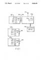
- FIG. 1is an illustration of the remote control system of the present invention including a plurality of portable units and a single base unit;
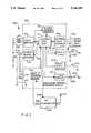
- FIG. 2is a block diagram of the circuit of one of the portable units
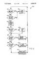
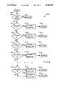
- FIG. 3is a logic sequence chart illustrating the basic operation of each of the portable units
- FIG. 4is a logic sequence chart illustrating the manner of resetting the identification code memories of each of the portable units to a factory preset code
- FIG. 5illustrates a logic sequence chart of the manner in which each of the portable units learns an identification code
- FIG. 6is a logic sequence chart of the manner in which each of the portable units transmits the data on the radio frequency signal in response to depression of a control button;
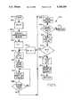
- FIG. 7is a block diagram of the circuits of the base unit in accordance with the preferred embodiment of the present invention.
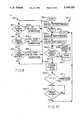
- FIG. 8is a flow chart illustrating the basic operation of the base unit
- FIG. 9is a flow chart illustrating control of the operation of the base unit in response to receipt of a radio frequency signal from a portable unit
- FIG. 10is a flow chart illustrating the manner in which the base unit teaches an identification code to a portable unit.
- FIG. 11is a flow chart illustrating the operation in which the identification code of the base unit is specified.
- FIG. 1illustrates the remote control system in accordance with the preferred embodiment of the present invention including a plurality of portable units 200 and a single base unit 700.
- Each portable unit 200includes four control buttons: control buttons 201, 202, 203 and 204. Each of these control buttons is preferably a momentary contact push button switch.
- each portable unit 200includes an asynchronous communication port 205.
- Each portable unit 200likewise includes a signaling light emitting diode 206, which signals to the operator the operation of the portable unit.
- a hidden reset switchwhich enables resetting of one or more of the memories of the portable unit 200.
- a hidden antennafor transmission of the radio frequency remote control signal. This antenna is contained within portable unit 200 in accordance with the prior art.
- Base unit 700is responsive to radio frequency signals transmitted by one of the portable units 200. These radio frequency signals are received via antenna 701.
- the base unit 700further includes a signaling light emitting diode 702 which signals the combined memory reset/identification code specification operation of base unit 700.
- Base unit 700includes a single momentary contact push button switch 703 which is employed to activate the combined reset/identification code selection operation.
- Base unit 700includes asynchronous communication port 704 which is adapted for mating with each of the asynchronous communication ports 205 of the portable units 200. In a manner which will be more fully described below, base unit 700 is enabled to transmit its identification code to a portable unit 200 via the mating asynchronous communication ports 205 and 704. This enables the portable unit 200 to store this identification code within one of its memories.
- base unit 700is coupled to utilization device 705.
- base unit 700is permitted to transmit control signals to utilization device 705.
- utilization device 705is an automatic garage door operator.
- each portable unit 200can control the garage door operation.
- an automatic garage door operatoris merely an example of a utilization device 705 which may be controlled by this system.
- FIG. 2illustrates in block diagram form the construction of a portable unit 200 in accordance with the preferred embodiment.
- FIGS. 3 to 6illustrate logic sequences for control of the operation of central logic unit 211 illustrated in FIG. 2.
- FIG. 7illustrates in block diagram form the preferred embodiment of base unit 700.
- FIGS. 8 to 11illustrate flow charts of a control program for control of central processing unit 711 illustrated in FIG. 7 for practicing the present invention.
- FIG. 2illustrates in block diagram form the preferred embodiment of portable unit 200.
- the major electronic portions of portable units 200are embodied in application specific integrated circuit 210.
- Various other partssuch as momentary push button switches 201 to 204, asynchronous communication port 205, light emitting diode 206, battery 231, capacitor 232, resistors 234 and 237, reset switch 236 and transmitter 240 are coupled to application specific integrated circuit 210.
- all of these partsare mounted on a single printed circuit board. Provision of the major portions of portable unit 200 within application specific integrated circuit 210 enables all of these parts to be placed within a generally handheld container.
- the power requirements of this portable unit 200are very modest, enabling battery 231 to be of the low power 9-volt transistor radio type.
- Special purpose integrated circuit 210includes a number of individual parts formed on a single integrated circuit device. The major control and processing functions of application specific integrated circuit 210 are performed by central logic unit 211. Central logic unit 211 is connected to all other circuits of application specific integrated circuit 210 in a manner that is known in the art.
- Central logic unit 211is bi-directionally coupled to identification code volatile memory 212.
- identification code volatile memory 212is capable of storing four multi-bit identification codes which may be employed by portable unit 200 in radio frequency transmissions.
- Central logic unit 211can recall identification codes from identification code volatile memory 212 and can store identification codes in identification code memory 212.
- Identification code volatile memory 212is preferably formed of static random access memory. Static random access memory is preferred over dynamic random access memory because of its lower power requirements.
- Central logic unit 211is capable of performing predetermined logic functions for control of the operation of portable unit 200.
- FIGS. 3 to 6illustrate in flow chart form the logic sequences preferably embodied within central logic unit 211.
- Central logic unit 211is connected to various input and output devices on application specific integrated circuit 210.
- the first of theseis input buffers 213.
- Input buffers 213is separately coupled to the momentary contact push button switches 201, 202, 203 and 204.
- a common connection from one terminal of each of momentary contact push button switches 201, 202, 203 and 204is connected to the regulated voltage supply V reg from power supply control 214.
- V regfrom power supply control 214.
- Input buffers 213preferably includes some form of contact debounce, enabling a clean input signal to be applied to central logic unit 211.
- Input buffers 213supply the properly conditioned input signals to central logic unit 211 indicating which one or more of the control buttons 201, 202, 203 or 204 has been depressed. This is the preferred method of setting the control state of portable unit 200. As will be described below, other types of switches could connect the regulated voltage supply V reg to these input terminals of input buffers 213. The essential point is that input buffers 213 is triggered to a particular control state.
- Central logic unit 211is further coupled to power supply control 214.
- Power supply control 214is coupled to the positive terminal of battery 231 and generates a regulated voltage supply V reg .
- Power supply control 214provides proper power conditioning to provide electric power from battery 231 via regulated voltage supply V reg .
- This function of power supply control 214is known in the art.
- This voltage V regis employed to power the circuits of application specific integrated circuit 210.
- Power supply control 214is further separately coupled to identification code volatile memory 212 in a manner that will be discussed below.
- the regulated voltage supply V regis further separately coupled to switches 201, 202, 203 and 204 and to capacitor 232. This supplies electric power to charge capacitor 232 from battery 231. This serves to store an amount of electric energy within capacitor 232.
- power supply control 214is separately coupled to identification code volatile memory 212.
- the electric power to operate identification code volatile memory 212is separately supplied to this memory via a separate line from power supply control 214.
- identification code volatile memory 212is powered via regulated voltage supply V reg like other portions of application specific integrated circuit 210.
- Power supply control 214monitors the voltage received from battery 231. In the event that battery 231 is removed from the circuit, such as for replacement of a depleted or nearly depleted battery, power supply control 214 continues to supply continuous electric power to identification code volatile memory 212 via the separate power line from electric energy stored within capacitor 232. Power supply control 214 thus ensures continuous supply of electric power to identification code volatile memory 212 during removal and replacement of battery 231.
- Application specific integrated circuit 210includes an optional time out function. This time out function is achieved as follows. At times when the optional time out function may be employed, central logic unit 211 senses the voltage on line 215. As illustrated in dashed lines in FIG. 2, line 215 is optionally connected at terminal 233 to either the voltage supply V reg or to ground. If the voltage on line 215 is V reg , then no time out function is implemented. If the voltage on line 215 is ground, then the optional time out function is implemented. Central logic unit 211 counts pulses from clock 219 in a counter. When the count reaches a number predetermined in manufacture of application specific integrated circuit 211, then the time out occurs. Thus the same application specific integrated circuit 211 can optionally provide this time out function depending upon the connection to line 215.
- Transmit power switch 216controls the supply of electric power to radio frequency transmitter 240. Transmit power switch 216 is controlled by central logic unit 211. Radio frequency transmitter 240 is powered directly from battery 231 via the voltage V dd . Transmit power switch 216 is further coupled to transmitter 240 for optional connection to ground. During standby operation of portable units 200, central logic unit 211 controls transmit power switch 216 to disconnect radio frequency transmitter 240 from ground. Therefore, transmitter 240 consumes no electric power under these circumstances. When a radio frequency transmission is desired, central logic unit 211 controls transmit power switch 216 to connect radio frequency transmitter 240 to ground enabling the supply of electric power to radio frequency transmitter 240. Central logic unit 211 is further coupled to a data input of radio frequency transmitter 240 for control of the modulation of the radio frequency signal transmitted by radio frequency transmitter 240. This modulation will be further described below.
- Central logic unit 211is bi-directionally coupled to asynchronous communication controller 218 which is further coupled to asynchronous communication port 205.
- FIG. 2illustrates asynchronous communication port 205 including four lines: ready; strobe; data; and ground.
- central logic unit 211communicates with asynchronous communication controller 218 for receipt of data from asynchronous communication port 205.
- the communications protocol employed in the preferred embodimentwill be fully described below.
- Central logic unit 211has its operations timed by clock 219. The particular clock rate of clock 219 is controlled by resistor 234 and capacitor 235 coupled to clock 219. Note that clock 219 is controlled by central logic unit 211. Central logic unit 211 enables clock 219 only when an input is received via input buffers 213 or asynchronous communication controller 218. This serves to reduce the electric power consumed by application specific integrated circuit 210 and extend the life of battery 231 by idling this circuit when no processing is required.
- Central logic unit 211is coupled to reset input buffer 220 which is in turn coupled to reset momentary contact push button switch 236. Upon depression of reset momentary contact push button switch 236, the input of reset input buffer 220 is connected to ground. Upon detection of this event, reset input buffer 220 signals this to central logic unit 211 which takes action in accordance with the logic sequences disclosed below.
- Central logic unit 211is coupled to light emitting diode driver 221.
- Light emitting diode driver 221is coupled to drive light emitting diode 206.
- Resistor 237is included in series with light emitting diode 206 to limit the current supplied through light emitting diode 206.
- Central logic unit 211provides a signal to light emitting diode driver 221 which sinks current to turn light emitting diode 206 on for signaling purposes. The time at which such signaling will occur will be fully described below in conjunction with FIGS. 3, 4, 5 and 6.
- FIGS. 3, 4, 5 and 6These logic sequence charts illustrate the sequence of logic within central logic unit 211. These logic sequence charts are not intended to illustrate the exact details of operation of central logic unit 211. Rather, these logic sequence charts illustrate the general overall steps necessary for control of central logic unit 211. Those skilled in the art of control logic design would be able to construct central logic unit 211 in accordance with this description to embody the present invention. Note that it is feasible to construct central logic unit 211 as the central processing unit in a microprocessor device. Those skilled in the art of microprocessor programing would be able to provide the exact program for control of such a central processing unit from these logic sequence charts, once the particular central processing unit is selected with its corresponding instruction set.
- central logic unit 211operations performed by central logic unit 211. In some instances these operations will be more properly understood as performed by other portions of application specific integrated circuit 210. However, these operations will be under the supervision and control of central logic unit 211 and therefore the logic sequence of central logic unit 211 will generally be in accordance with these logic sequence charts.
- FIG. 3illustrates logic sequence 300 for control of the operation of central logic unit 211.
- this logic sequencetogether with the logic subsequences referred to herein and illustrated in FIGS. 4, 5 and 6 are permanently embodied in central logic unit 211.
- This logic sequenceis executed in accordance with the principles known in the art.
- Logic sequence 300includes a continuously executed set of tests to determine the operation to be performed next. Logic sequence 300 first tests to determine whether the battery 231 is present (decision block 301). This information is obtained from power supply control 214 which detects an open circuit condition at the power input line. In the event that battery 231 has been removed then central logic unit 211 causes application specific integrated circuit 210 to enter a low power mode (processing block 302). This is achieved by controlling clock 219 to shut down, thereby reducing the electric power consumed by application specific integrated circuit 211. Identification code volatile memory 212 is powered via the separate power line from power supply control 214 from energy stored in capacitor 232. No normal functions of application specific integrated circuit 210 are permitted while battery 231 is removed.
- logic sequence 300tests whether or not one or more of control buttons 201, 202, 203 or 204 have been depressed (decision block 303). This information is obtained from input buffers 213 which continuously monitors the state of the control buttons 201, 202, 203 and 204. In the event no control button is depressed then central logic unit 211 causes application specific integrated circuit 210 to enter the low power mode (processing block 302) as described above. These tests are continuously repeated until one or more of the control buttons 201, 202, 203 and 204 is depressed.
- central logic unit 211causes application specific integrated circuit 210 to enter the normal power mode (processing block 304). This is achieved by controlling clock 219 to operate, thereby allowing normal operation of application specific integrated circuit 211 powered from battery 231.
- logic sequence 300tests to determine whether the voltage from battery 231 is low (decision block 305). This low voltage determination is made by power supply controller 214 and signaled to central logic unit 211. In the event that the battery voltage is not below a certain threshold then the light emitting diode 206 is turned on (processing block 306). This is achieved by sending the proper control signal to light emitting diode driver 221.
- logic sequence 300next tests to determine whether or not the reset signal is received from reset input buffer 220 (decision block 307). This indicates that reset push button 236 was depressed at the time of depression of one of the control button 201, 202, 203, 204. If such a reset memory signal has been received then logic sequence 300 executes a reset memory logic subsequence (processing block 308). This reset memory logic subsequence 308 is further described below in conjunction with FIG. 4. Upon execution of this logic subsequence control returns to decision block 301 to repeat the continuous tests for battery removal (decision block 301) and depression of the control buttons 201, 202, 203 and 204 (decision block 303).
- logic sequence 300tests to determine whether or not a digital low signal is applied to the strobe input of asynchronous communication port 205 (decision block 309).
- Asynchronous communication controller 218monitors the strobe line of asynchronous communication port 205 and signals central logic unit 211 when a low signal is received at this line.
- logic sequence 300executes an identification code learn logic subsequence (processing block 310). This identification code learn logic subsequence 310 is more fully described below in conjunction with FIG. 5.
- controlUpon completion of this logic subsequence control returns to decision block 301 to repeat the continuous test for removal of battery 231 (decision block 301) and depression of the control buttons 201, 202, 203 and 204 (decision block 303).
- logic sequence 300enters the serial data transmission logic subsequence (processing block 311). This involves control of radio frequency transmitter 240 to transmit a radio frequency signal to base unit 700.
- the serial data transmission logic subsequence 311is further described below in conjunction with FIG. 6.
- controlreturns to decision block 301 to repeat the continuous test for removal of battery 231 (decision block 301) and depression of the control buttons 201, 202, 203 and 204 (decision block 303).
- FIG. 4illustrates reset memory logic subsequence 308 described above in conjunction with FIG. 3.
- Reset memory logic subsequence 308enables the particular identification code stored within identification code vault memory 212 corresponding to one of the control buttons 201, 202, 203 or 204 to be reset to a factory preset code.
- this factory preset codeis all ones. This factory preset code is called the reset code.
- Reset memory logic subsequence 308is begun by a start block 401.
- Reset memory logic subsequence 308tests to determine whether or not the control A input is received (decision block 402).
- Input buffers 213generates a control A input upon depression of control button 201.
- the identification code memory corresponding to the control A inputis set to this reset code (processing block 403). If the control A input has not been received then reset memory logic subsequence 308 tests to determine whether or not the control B input has been received (decision block 404). If this is the case then the memory corresponding to the control B input is set to the reset code (processing block 405). In the event that the control B input has not been received then reset memory logic subsequence 308 tests to determine whether or not the control C input has been received (decision block 406). If the control C input was received then the identification code corresponding to this control input is reset (processing block 407). In the event that the control C input has not been received then the control D input must have been received. Note that decision block 303 of FIG. 3 has previously determined that at least one control button has been depressed. In this event the memory corresponding to control D signal is reset (processing block 408).
- reset memory logic subsequence 308executes a short delay time (processing block 409).
- Next reset input logic subsequence 308turns off light emitting diode 206 (processing block 410). This is achieved by sending the proper control signal to light emitting diode driver 221.
- Reset memory logic subsequence 308is then exited by a return block 411, returning control to main logic sequence 300.
- the useris enabled to reset any of the identification code memories corresponding to control buttons 201, 202, 203 or 204 by simultaneously depressing the particular control button and the reset button 236.
- Light emitting diode 206is illuminated at the start of this process and then turned off after reset of the particular memory, thereby signaling to the user the completion of this reset operation.
- FIG. 5illustrates in logic sequence chart form the identification code learn logic subsequence 310.
- identification code learn logic subsequence 310is entered whenever a control button is pressed and asynchronous communications controller 218 detects a digital low signal at the strobe line of the asynchronous communication port 205.
- Identification code learn logic subsequence 310is entered via start block 501.
- Identification code learn logic subsequence 310first executes a delay (processing block 502). This delay serves to ensure that the portable unit 200 and the base unit 700 have each reached the proper state prior to transmission of the identification code data.
- identification code learn logic subsequence 310identifies the corresponding memory location within identification code volatile memory 212 which corresponds to the particular control button depressed (decision block 503).
- identification code learn logic subsequence 310sets a counting variable N equal to 1 (processing block 504). This counting variable N is employed to indicate when transfer of the entire identification code is complete.
- a 20-bit identification codeis transmitted as five four bit nibbles.
- a countis set to 15 (processing block 505) and central logic unit 211 instructs asynchronous communication controller 218 to generate a ready signal (processing block 506).
- Asynchronous communications controller 218provides a signal on the ready line of asynchronous communications port 205 indicating portable unit 200 is ready to receive data corresponding to an identification code.
- Identification code learn logic subsequence 310then enters a counting loop for one nibble of the identification code.
- the count(previously set to 15 in processing block 505) is decremented on the detection of a pulse on the data line of asynchronous communications port 205 (processing block 507).
- Identification code learn logic subsequence 310next tests to determine whether or not the strobe signal on strobe line of asynchronous communications port 205 is a digital high (decision block 508). If this strobe signal is still a digital low then identification code learn logic subsequence 310 returns to processing block 507 to count further pulses. If, on the other hand, the signal on the strobe line of asynchronous communication port 205 is a digital high, the transmission of a particular nibble of the identification code is complete as signaled by the base unit 700. At this point, asynchronous communications controller 218 sends a not ready signal via the ready line of asynchronous communications port 205 (processing block 509).
- Identification code learn logic subsequence 310next tests to determine whether the same control input is received (decision block 510). This is determined by the signal provided by input buffers 213 to central logic unit 211. If the same control input is not received then the identification code learn logic subsequence 308 is aborted via return block 511, which returns control to logic sequence 300 illustrated in FIG. 3. This ensures that the same control button 201, 202, 203 or 204 is depressed during the entire identification code learning process, ensuring that the user intended the storage of the identification code received from the base unit 700 in the corresponding portion of identification code volatile memory 212.
- identification code learn logic subsequence 310sets a portion of the code corresponding to the counting variable N equal to the resulting count (processing block 512). The identification code learn logic subsequence 310 then tests to determine whether the counting variable N equals five (decision block 513). If the counting variable does not equal five then all of the identification code has not been transmitted to the portable unit. In this event, the counting variable N is incremented (processing block 514) and control returns to processing block 505 to repeat the process of receiving the next nibble of data.
- identification code learn logic subsequence 310turns the light emitting diode 206 off (processing block 515) indicating to the user that the data transfer process is complete.
- identification code learn logic subsequence 310decodes the five partial codes and stores the thus identified identification code in the appropriate memory (processing block 516).
- each nibble of datacorresponds to the four bit binary representation of the count during the transmission of that particular nibble of data.
- the resultant identification codeis the concatenation of these five nibbles of data.
- FIG. 6illustrates in logic sequence chart form serial data transmission logic subsequence 311.
- Serial data transmission logic subsequence 311causes the transmission of a radio frequency signal modulated by a particular code for control of base unit 700.
- Serial data transmission logic subsequence 311is begun via start block 601. This logic subsequence first recalls the data stored in the corresponding memories A, B, C and D (processing block 602) which correspond to the respective control buttons 201, 202, 203 and 204.
- Serial data transmission logic subsequence 311then tests to determine whether all of these memories are reset (decision block 603). Recall that the reset identification code is the factory preset identification code. In accordance with the preferred embodiment, this reset code is all ones. If all the memories are reset, then the serial data transmission logic subsequence 311 sets the identification code equal to this reset code (processing block 604) and sets a channel number equal to channel 1 (processing block 605).
- serial data transmission logic subsequence 311tests to determine whether or not a plurality of control buttons 201, 202, 203 and 204 have been pushed (decision block 606). In the event that a plurality of the control buttons have been pushed then serial data transmission logic subsequence 311 sets the identification code equal to the identification code stored within memory A (processing block 607). The channel is set equal to a number from three to fifteen corresponding to the particular control buttons pressed (processing block 608).
- depression of control button 201corresponds to a digital "0001”
- depression of control button 202corresponds to a digital "0010”
- depression of control button 203corresponds to a digital "0100”
- depression of control button 204corresponds to a digital "1000.”
- the particular channel numberequals the sum of the digital numbers for the particular control buttons depressed.
- serial data transmission logic subsequence 311tests to determine whether or not the identification code memory corresponding to this single control button depressed is reset (decision block 609). If this is not the case then the identification code equals the identification code stored in the memory corresponding to the particular control button 201, 202, 203 or 204 depressed (processing block 610) and the channel number is set equal to channel 1 (processing block 611). In the event that the corresponding memory of the single control button pushed is reset then the identification code is set equal to the identification code stored in memory A (processing block 612) and the channel is set corresponding to the particular control button depressed in accordance with the above digital identification (processing block 613).
- the output produced by transmitter 240corresponds to a concatenation of this identification code and the channel number (processing block 614).
- Serial data transmission logic subsequence 311next turns on radio frequency transmitter 240 (processing block 615). This is achieved by central logic unit 211 sending the appropriate signal to transmit power switch 216 to connect radio frequency transmitter 240 to ground, thereby permitting supply of electric power.
- the central logic unitdetects whether or not the voltage at the timer line 215 is ground (decision block 616). Recall that the optional connection to this timer line 215 determines whether a time out function is implemented. If this is connected to ground then the internal counter is started (processing block 617). As described above, a counter counts clock pulses from clock 219 until a predetermined number is reached indicating the time out. In accordance with the preferred embodiment of the present invention the predetermined number is preset in construction relative to the rate of clock 219 to achieve a time of approximately 1.5 seconds. This nominal time of 1.5 seconds is selected to achieve a worst case time of no more than 2 seconds. If this line is not connected to ground, then the timer is not started and no time out can occur.
- Serial data transmission logic subsequence 311next transmits the output code (processing block 618) via a signal from central logic unit 211 turning on and off the modulation of radio frequency transmitter 240.
- the ones and zeros of the digital output code transmittedare transmitted in pulse code format.
- a particular bit periodis set equal to four subperiods.
- the transmission of a digital oneis the transmission for three subperiods and nontransmission for the last subperiod. Transmission of a digital zero is transmission for the first subperiod and nontransmission for the second, third and fourth subperiods.
- Radio frequency transmitter 240transmits the thus modulated radio frequency signal via antenna 241.
- serial data transmission logic subsequence 311enters a blank interval (processing block 619) during which no modulated transmissions are made. This blank interval is preferably as long as or slightly longer than the time needed to transmit the identification code and channel number.
- Serial data transmission logic subsequence 311next tests to determine whether the same control buttons are depressed (decision block 620). In the event that the same control buttons are depressed, then serial data transmission logic subsequence 311 tests to determine whether or not a time out has occurred (decision block 621). Note that such a time out is optional and if timer line 215 is connected to the regulated voltage supply V reg no time out will ever occur.
- controlreturns to processing block 618 to repeat the transmission of the output code and the blank interval.
- control buttonsare depressed transmission of the output code followed by the blank interval is repeated until the a time out occurs (if such a time out function is selected). If the time out function is not selected, transmission continues until the control button or buttons are released.
- serial data transmission logic subsequence 311turns off light emitting diode 206 (processing block 623). This indicates to the user that the serial data transmission process is complete. Lastly, serial data transmission logic subsequence 311 is exited via return block 624.
- FIG. 7illustrates in block diagram form the Preferred embodiment of base unit 700.
- Base unit 700 illustrated in FIG. 7includes elements already illustrated in FIG. 1: antenna 701; light emitting diode 702; reset/identification code selection push-button 703; and asynchronous communication port 704.
- base unit 700is constructed in the form of a microprocessor control system. Major control and operating functions of base unit 700 are controlled by central processing unit 711.
- Central processing unit 711is coupled to an identification code nonvolatile memory 712.
- the identification code of the base unitis stored within identification code nonvolatile memory 712.
- identification code nonvolatile memory 712consists of electrically erasable programmable read only memory (EEPROM).
- EEPROMelectrically erasable programmable read only memory
- identification code nonvolatile memory 712will be further discussed below. It is technically feasible, and may be desirable in some instances, to construct base unit 700 without the capability of altering its identification code. This may be useful in the primary level of a multilevel security system. In this event identification code nonvolatile memory 712 would be embodied by read only memory. Central processing unit 711 is further bi-directionally coupled to read only memory 713 which stores the control program for central processing unit 711.
- Radio frequency signals received from one of portable units 200are received via antenna 701 and coupled to radio frequency receiver 714.
- the received signalsare then coupled to demodulator 715 which produces an identification code corresponding to the identification code modulated on the received radio frequency signal in accordance with the particular modulation technique employed.
- This identification codeis supplied to central processing unit 711.
- Electric power for operation of base unit 700preferably comes from 60 Hertz AC electric power mains 716.
- Power supply circuit 717is coupled to power supply mains 716 and produces power on one or more power supply buses +V. Also coupled to power supply circuit 717 is a zero crossing detector circuit 718 which is responsive to the zero crossings of the 60 Hertz AC power received from electric power mains 716. Zero crossing detector circuit 718 transmits a signal to central processing unit 711 upon detection of each zero crossing of the 60 Hertz AC electric power mains 716.
- Central processing unit 711is coupled to asynchronous communication controller circuit 719 which is turn connected to a asynchronous communication port 704.
- Asynchronous communication port 704is illustrated as including the following lines: ready; strobe; data; and ground. These correspond to the connections illustrated in FIG. 2 of asynchronous communication port 205.
- Asynchronous communication ports 205 and 704are constructed to mate for transmission of data thereacross.
- Asynchronous communication controller 719is constructed in accordance with the prior art.
- Central processing unit 711is coupled to identification code program input 720.
- Identification program input 720is further coupled to reset/identification code selection button 703. Upon depression of button 703, identification code program input 720 transmits a signal to central processing unit 711.
- Central processing unit 711is further connected to light emitting diode driver 721.
- Light emitting diode driver 721sinks an appropriate current from the series connection of light emitting diode 702 and resistor 722 for illumination of light emitting diode 702 in accordance with commands received from central processing unit 711.
- Base unit 700further includes a plurality of function driver circuits 723, 725 to 741 which are coupled to respective utilization devices 724, 726 to 742.
- the function driver circuits 723 to 741provide the appropriate signal to respective utilization devices 724 to 742 for remote control operation in accordance with signals received from central processing unit 711. This operation will be further detailed below in conjunction with the operation of base unit 700.
- FIGS. 8, 9, 10 and 11together illustrate the control program for control of central processing unit 711 of base unit 700.
- This control programis permanently stored in read only memory 713 upon construction of base unit 700.
- These flow chartsare not intended to illustrate the exact detailed steps for control of central processing unit 711. Rather, these flow charts illustrate the general overall steps necessary for operation of central processing unit 711 in accordance with the present invention. Those skilled in the art of microprocessor programming would be enabled to provide the exact program necessary for practicing the present invention from these flow charts, once the particular microprocessor to embody central processing unit 711 is selected with its corresponding instruction set.
- FIG. 8illustrates control program 800 for control of the operation of base unit 700.
- Control program 800is a continuous test loop which tests for certain events and performs subroutines based upon these events.
- Program 800tests to determine whether or not a radio frequency signal has been received (decision block 801).
- any radio frequency signal transmitted by a portable unit 200is received via antenna 701 and radio frequency receiver 714.
- Demodulator 715demodulates any identification code modulated on such a radio frequency transmission and supplied this identification code to central processing unit 711.
- central processing unit 711is alerted to the receipt of such an radio frequency signal by receipt of the demodulated identification code from demodulator 715. If such a radio frequency signal has been received then program 800 executes radio frequency signal subroutine 802.
- program 800tests to determine whether or not the ready signal has been received on asynchronous communication port 704. If this is the case then the identification code teach subroutine is executed (processing block 804).
- program 800tests to determine whether or not the identification code program button 703 has been depressed (decision block 805). If this identification code program button has been depressed then program 800 executes an identification code setting subroutine (processing block 806). In the event that none of these signals are received program 800 returns to decision block 801 to repeat the set of tests.
- FIG. 9illustrates radio frequency signal subroutine 802.
- Radio frequency signal subroutine 802is begun via start block 901. This subroutine first tests to determine whether or not the identification code modulated on the received radio frequency signal demodulated by demodulator 715 matches the base unit identification code stored in identification code nonvolatile memory 712 (decision block 902). If this is not the case then base unit 700 takes no action and radio frequency signal subroutine 802 is exited via return block 903. This returns control to the test loop illustrated in FIG. 8.
- radio frequency signal subroutine 802performs differing actions depending upon the channel number of the received radio frequency signal. Radio frequency signal subroutine 802 tests to determine whether or not the received signal includes channel number 1 (decision block 904). In the event that the received signal indicates channel number 1, radio frequency signal subroutine 802 activates the channel 1 function (processing block 905). This is achieved by central processing unit 711 sending the appropriate signal to function driver 723. Function driver 723 in turn supplies a corresponding signal to the first utilization device 724. Radio frequency signal subroutine 802 is then exited via return block 906, returning control to the test loop illustrated in FIG. 8.
- radio frequency signal subroutine 802tests to determine whether or not the received signal includes channel number 2 (decision block 907). If the received signal indicates channel number 2, radio frequency signal subroutine 802 activates the channel 2 function (processing block 908) by central processing unit 711 sending the appropriate signal to function driver 725. Function driver 725 in turn supplies a corresponding signal to second utilization device 726. Radio frequency signal subroutine 802 is then exited via return block 909, returning control to the test loop illustrated in FIG. 8.
- Radio frequency signal subroutine 802then tests in order whether the channel number was channel number 3 (decision block 910), channel number 4 (decision block 913) and so on through channel number 14 (decision block 943). If the received channel number was channel number 3, then radio frequency signal subroutine 802 activates the channel 3 function (processing block 911) and then exits to the test loop illustrated in FIG. 8 (return block 912). Likewise, if channel number 4 was received, then radio frequency signal subroutine 802 activates the channel 4 function (processing block 914) and then exits to the test loop illustrated in FIG. 8 (return block 915). Similar functions are performed for channel numbers 5 to 13.
- channel number 14is received (decision bloc 943) then the channel number 14 function is executed (processing block 944) and subroutine 802 is exited via return block 945.
- the channel number 14is not indicated then the channel number must have been channel number 15.
- the channel number 15 functionis executed (processing block 946) and then radio frequency signal subroutine 802 is exited via return block 947.
- FIG. 10illustrates in flow chart form the identification code teach subroutine 804.
- Identification code teach subroutine 804is entered via start block 1001.
- Identification code teach subroutine 804first recalls the identification code from identification code nonvolatile memory 712 (processing block 1002).
- the subroutinenext sets a counting variable N equal to 1 (processing block 1003).
- Next the appropriate nibble of data corresponding to the counting variable Nis encoded (processing block 1004).
- a countis set equal to the binary number corresponding to this particular nibble of data (processing block 1005).
- Identification code teach subroutine 804next enters a loop to transfer the present nibble of the identification code. Identification code teach subroutine 804 tests the count to determine whether or not it equals 0 (decision block 1006). If the count does not equal 0 then the proper number of counts have not been transmitted to the portable unit 200. In such an event, identification code teach subroutine 804 sends a pulse (processing block 1007), the count is decremented (processing block 1008) and control returns to processing block 1006. Identification code teach subroutine 804 remains in this loop until the count has been decremented to 0. This loop causes transmission of pulses equal to the number represented by the nibble being transmitted. Note the structure of the loop putting the test for zero (decision block 1006) prior to transmitting the pulse (processing block 1007) permits the identification code teach subroutine 804 to transmit zero pulses corresponding to a nibble of "0000.”
- identification code teach subroutine 804sets the strobe signal to a digital high (processing block 1009). This signals to the portable unit 200 that the complete nibble has been transmitted. The subroutine next tests to determine whether or not the counting variable N equals 5 (decision block 1010). If this is the case then the entire identification code has been transmitted to the portable unit 200 and the identification code teach subroutine 804 is exited via return block 1011. In the event that the counting variable N does not equal 5, then the entire identification code has not been transmitted to the portable unit 200. In such an event identification code teach subroutine 804 tests to determine whether or not a ready signal is received from the portable unit 200 (decision block 1012).
- the identification code teach subroutine 804continues to test for the receipt of this ready signal, indicating that the portable unit 200 is ready for receipt of the next nibble of data. Once this occurs then the counting variable N is incremented (processing block 1013) and control returns to processing block 1004 to transmit the next nibble of data. Identification code teach subroutine 804 remains in this loop transmitting the nibbles of data until the entire identification code has been transmitted to the portable unit 200.
- FIG. 11illustrates in flow chart form identification code setting subroutine 806.
- the identification code setting subroutine 806is actuated by depression of the identification code program button 703.
- Identification code setting subroutine 806enables the operator to set either the reset code or a randomly selected code as the identification code of the base unit 700.
- Identification code setting subroutine 806is entered via start block 1101. This subroutine first turns on light emitting diode 702 (processing block 1102). The subroutine then starts a reset timer (processing block 1103).
- Identification code setting subroutine 806next tests to determine whether or not the identification code program button 703 is still pressed (decision block 1104).
- the identification codeis set equal to the predetermined reset code (processing block 1105). As explained above, this predetermined reset code is equal to 20 ones in the preferred embodiment.
- the identification code setting subroutine 806is then complete and exited by return block 1106.
- identification code setting subroutine 806tests to determine whether or not the reset timer has expired (decision block 1107). If this reset time has not expired then control returns to decision block 1104 to repeat the test on the condition of the identification code program button 703. The identification code setting subroutine 806 remains in this loop until either the identification code program button 703 is released (decision block 1104) or the reset time has expired (decision block 1107).
- Identification code setting subroutine 806turns off light emitting diode 702 (processing block 1108). This indicates to the operator that the time interval during which the reset code can be set has now expired.
- Identification code setting subroutine 806next initializes a first count F (processing block 1109).
- the first count Fis set equal to a subset of the bits of the identification code.
- First count Fis initialized by recalling the stored identification code and loading the subset of bits corresponding to the first count F into the counter.
- Identification code setting subroutine 806next enters a counting loop whose exit is dependent upon the state of the identification code program button 703. Firstly, identification code setting subroutine 806 tests to determined whether or not the identification code button 703 is still depressed (decision block 1110). If the identification code program button 703 is still depressed then identification code setting subroutine 806 tests to determine whether or not the count F has overflowed (decision block 1111). If this is the case then the On or Off state of the light emitting diode 702 is toggled (processing block 1112). In either case the first count F is incremented (processing block 1113). Control then returns to decision block 1110 to test to determine the state of the identification code program button 703.
- Identification code setting subroutine 806remains in this loop until the identification code program button 703 is released (decision block 1110).
- the value of first count Fis dependent upon the length of time that the identification code program button 703 is depressed. Also note that the On or Off status of light emitting diode 702 changes each time first count F overflows.
- identification code setting subroutine 806ensures that light emitting diode 702 is turned off (processing block 1114).
- a second count Sis initialized (processing block 1115).
- the second count Sis set equal to the remaining subset of the bits of the current identification code. Second count S is initialized by loading this remaining subset of bits into the counter.
- Identification code setting subroutine 806then tests to determine whether or not zero crossing detector 719 has detected the next zero crossing of the 60 hertz power (decision block 1116). If the next zero crossing has not been detected then the second count S is incremented (processing block 1117). Control returns to decision block 1116 for detection of the next zero crossing of the 60 hertz power. Control remains in this loop with the second counting variable S incremented until the zero crossing detector 719 determines the next zero crossing. When this zero crossing is detected identification code setting subroutine 806 sets the identification code of the base unit 700 equal to the concatenation of the first count F and the second count S (processing block 1118). Identification code setting subroutine 806 is now complete and is exited via return block 1119.
- the system of the present inventionpermits very flexible implementation of a remote control security system.
- One envisioned embodimentuses the base unit 700 for control of an automatic garage door operator.
- the automatic garage door operatoris connected to base unit 700 as one of the utilization devices 724 to 742. Once installed base unit 700 is taught a identification code in the manner just described. A plurality of portable units 200 can learn this identification code from the base unit 700. Then the automatic garage door operator is controlled by base unit 700 in accordance with the "four function" protocol.
- This "four function" protocolis known in the art and includes the states of: door opening; stop; door closing; and stop.
- the automatic garage door operatoris advanced to the next state upon each receipt of a signal from the corresponding function driver 723 to 741.
- a remote control security systemcan be configured in several ways using the present invention because each portable unit 200 is capable of storing a plurality of identification codes.
- a single portable unitcould learn the identification code of a plurality of base units, permitting the single portable unit to operate each of several base units. This could be employed in a layered security system in which each of a number of portable units opens a primary gate, but only a single portable unit would open a particular one of a number of secondary gates.
- the capability of transmitting channel numbers corresponding to the control buttons pushedcan be used to implement two level security systems for a single location such as taught in our prior U.S. Pat. No. 4,847,542, entitled "AUTOMATIC GARAGE DOOR OPERATOR WITH REMOTE LOAD CONTROL" issued Jul. 11, 1989.
- the portable units 200transmit the identification code and channel 1 upon depression of control button A and the identification code and channel 2 upon depression of control button B.
- the base unit 700operates function driver 723 to produce the door signal and function driver 725 to produce the secure signal in the manner disclosed in this prior application.
- control buttons C and Dcan be employed for additional signaling functions such toggling the state of a lamp or other controlled device.
- This lamp or other devicemay be located remotely from the base unit 700 and controlled via a modulated signal on the power supply mains as disclosed in the above mentioned prior patent application.
- the present inventionmay also be advantageously employed in a security system.
- a number of portable units 200may be taught a single identification code and disposed at the locations of windows or doors which are to be monitored.
- a magnetic reed switch or other switch controlled by the opening of the window or dooris connected to input buffers 213 of application specific integrated circuit 210. It is preferable that each such switch be connected to activate a unique set of control inputs, thereby activating the transmission of a unique channel number.
- some portable units 200can be coupled to activate a unique channel via smoke or fire alarms. Note that there are 15 such unique channel numbers available in the preferred embodiment described in this application. In this use it would be advantageous to employ the optional time out function at each portable unit 200 to minimize battery drain and to prevent continuous radio frequency transmissions.
- the base unit 700thus has the information in the channel number regarding the identity of the open portal or the alarm tripped and can control one or more utilization devices in response to these signals.
- the present inventionincludes the advantages of: providing an easy manner for setting the identification code in the base unit and in each portable unit; storing the identification code in a manner not discernible by visual inspection; and providing a flexible system adaptable to numerous uses.
Landscapes
- Physics & Mathematics (AREA)
- General Physics & Mathematics (AREA)
- Engineering & Computer Science (AREA)
- Computer Networks & Wireless Communication (AREA)
- Selective Calling Equipment (AREA)
Abstract
Description
Claims (24)
Priority Applications (1)
| Application Number | Priority Date | Filing Date | Title |
|---|---|---|---|
| US07/343,921US5148159A (en) | 1989-04-26 | 1989-04-26 | Remote control system with teach/learn setting of identification code |
Applications Claiming Priority (1)
| Application Number | Priority Date | Filing Date | Title |
|---|---|---|---|
| US07/343,921US5148159A (en) | 1989-04-26 | 1989-04-26 | Remote control system with teach/learn setting of identification code |
Publications (1)
| Publication Number | Publication Date |
|---|---|
| US5148159Atrue US5148159A (en) | 1992-09-15 |
Family
ID=23348262
Family Applications (1)
| Application Number | Title | Priority Date | Filing Date |
|---|---|---|---|
| US07/343,921Expired - Fee RelatedUS5148159A (en) | 1989-04-26 | 1989-04-26 | Remote control system with teach/learn setting of identification code |
Country Status (1)
| Country | Link |
|---|---|
| US (1) | US5148159A (en) |
Cited By (166)
| Publication number | Priority date | Publication date | Assignee | Title |
|---|---|---|---|---|
| US5276692A (en)* | 1990-10-26 | 1994-01-04 | Samsung Electronics Co., Ltd. | Self-testing and mutual testing of multifunctional remote control transmitters |
| US5287210A (en)* | 1992-01-13 | 1994-02-15 | Siavash Sefidvash | Smart infrared controller |
| EP0602544A1 (en)* | 1992-12-15 | 1994-06-22 | DIEHL GMBH & CO. | Remote control device |
| EP0618097A1 (en)* | 1993-03-31 | 1994-10-05 | WEBASTO THERMOSYSTEME GmbH | Remote control device |
| EP0651119A1 (en)* | 1993-11-01 | 1995-05-03 | Phisilog Research Limited | A transmitter for a remote control group |
| EP0660286A1 (en)* | 1993-12-22 | 1995-06-28 | PRASTEL S.r.L. | System for recognizing and managing codes for accessing multiple services |
| EP0688929A2 (en) | 1994-06-21 | 1995-12-27 | Microchip Technology Inc. | Secure self-learning |
| WO1996006499A3 (en)* | 1994-08-09 | 1996-04-11 | Philips Electronics Nv | Method of, and system for, transferring secure data |
| EP0803851A1 (en)* | 1996-04-24 | 1997-10-29 | Marantec Antriebs- Und Steuerungstechnik Gmbh & Co., Produktions Kg | Remote control |
| US5686904A (en)* | 1991-05-29 | 1997-11-11 | Microchip Technology Incorporated | Secure self learning system |
| US5729197A (en)* | 1996-02-22 | 1998-03-17 | Ultra Communications Corporation | Automatic, self-triggering alarm processing system and method |
| US5739748A (en)* | 1996-07-29 | 1998-04-14 | Flick; Kenneth E. | Method and apparatus for remotely alerting a vehicle user of a security breach |
| US5781143A (en)* | 1996-02-06 | 1998-07-14 | Rossin; John A. | Auto-acquire of transmitter ID by receiver |
| US5841866A (en)* | 1994-09-30 | 1998-11-24 | Microchip Technology Incorporated | Secure token integrated circuit and method of performing a secure authentication function or transaction |
| US5846120A (en)* | 1997-02-11 | 1998-12-08 | Rokenbok Toy Company | Toy tow trailer with self-leveling hitch assembly |
| WO1998055717A1 (en) | 1997-06-03 | 1998-12-10 | Microchip Technology Incorporated | Improved secure self learning system |
| EP0889453A3 (en)* | 1997-07-03 | 1999-02-03 | Ferport S.a.s. di M. Biassoni e C. | A programmable code remote control system |
| US5879221A (en)* | 1997-02-11 | 1999-03-09 | Rokenbok Toy Company | Toy bulldozer with blade float mechanism |
| US5885159A (en)* | 1996-08-13 | 1999-03-23 | Rokenbok Toy Company | System for, and method of, controlling the operation of toys |
| US5898386A (en)* | 1995-09-08 | 1999-04-27 | Sony Corporation | Electronic appliance system, electronic appliance and remote controller |
| US5897216A (en)* | 1996-09-18 | 1999-04-27 | Canon Kabushiki Kaisha | Reproducing apparatus having editing function |
| US5898369A (en)* | 1996-01-18 | 1999-04-27 | Godwin; Paul K. | Communicating hazardous condition detector |
| US5944607A (en)* | 1995-12-29 | 1999-08-31 | Rokenbok Toy Company | Remote control system for operating toys |
| US5964640A (en)* | 1997-02-11 | 1999-10-12 | Rokenbok Toy Company | Toy dump truck with automatic dumper mechanism |
| US5989096A (en)* | 1997-02-11 | 1999-11-23 | Rokenbok Toy Company | Toy fork lift vehicle with improved steering |
| US6025785A (en)* | 1996-04-24 | 2000-02-15 | The Chamberlain Group, Inc. | Multiple code formats in a single garage door opener including at least one fixed code format and at least one rolling code format |
| US6049289A (en)* | 1996-09-06 | 2000-04-11 | Overhead Door Corporation | Remote controlled garage door opening system |
| USRE36703E (en) | 1984-05-30 | 2000-05-16 | The Chamberlain Group, Inc. | Coding system for multiple transmitters and a single receiver for a garage door opener |
| US6154544A (en) | 1995-05-17 | 2000-11-28 | The Chamberlain Group, Inc. | Rolling code security system |
| US6175312B1 (en) | 1990-05-29 | 2001-01-16 | Microchip Technology Incorporated | Encoder and decoder microchips and remote control devices for secure unidirectional communication |
| US6191701B1 (en) | 1995-08-25 | 2001-02-20 | Microchip Technology Incorporated | Secure self learning system |
| US6247994B1 (en) | 1998-02-11 | 2001-06-19 | Rokenbok Toy Company | System and method for communicating with and controlling toy accessories |
| US6256019B1 (en) | 1999-03-30 | 2001-07-03 | Eremote, Inc. | Methods of using a controller for controlling multi-user access to the functionality of consumer devices |
| WO1999060530A3 (en)* | 1998-05-15 | 2001-08-02 | Hoermann Kg Antriebstechnik | Closing system which can be actuated by a signal and which is provided for doors or gates, and a method for operating such as system |
| US20020110242A1 (en)* | 2000-12-19 | 2002-08-15 | Bruwer Frederick Johannes | Method of and apparatus for transferring data |
| US6480095B1 (en)* | 1995-04-14 | 2002-11-12 | Omega Patents, L.L.C. | Vehicle control system including multi-digit control switch and associated methods |
| US20030016139A1 (en)* | 2001-07-17 | 2003-01-23 | Teich Rudor M. | Teach mode for remote control system |
| US20030016119A1 (en)* | 2001-07-17 | 2003-01-23 | Teich Rudor M. | Changeable coding for remote control system |
| SG94846A1 (en)* | 2000-06-28 | 2003-03-18 | Honda Motor Co Ltd | Keyless entry for vehicle sharing system |
| FR2834147A1 (en)* | 2001-12-21 | 2003-06-27 | Somfy | Domestic control transmitter/receiver matching system having receiver two transmitters matched with receiver responding each transmitter address and sending back/storing different address each transmitter |
| US20030151496A1 (en)* | 2002-02-11 | 2003-08-14 | The Chamberlain Group, Inc. | Device learning mode method |
| US20030174044A1 (en)* | 2002-03-15 | 2003-09-18 | Wayne-Dalton Corp. | Operator for a movable barrier and method of use |
| US6624740B2 (en)* | 1989-08-09 | 2003-09-23 | Fujitsu Ten Limited | Receiving apparatus |
| FR2837939A1 (en)* | 2002-03-26 | 2003-10-03 | Somfy | METHOD FOR REPROGRAMMING BIDIRECTIONAL OBJECTS |
| US20030214385A1 (en)* | 2002-05-20 | 2003-11-20 | Wayne-Dalton Corp. | Operator with transmitter storage overwrite protection and method of use |
| US6661350B1 (en) | 1999-09-24 | 2003-12-09 | Creative Commands Corporation | Miniature remote control system |
| US20030227407A1 (en)* | 2002-03-22 | 2003-12-11 | Yuen Henry C. | Method and system for reverse universal remote control feature |
| US6690796B1 (en) | 1995-05-17 | 2004-02-10 | The Chamberlain Group, Inc. | Rolling code security system |
| US20040066277A1 (en)* | 2002-10-07 | 2004-04-08 | Murray James S. | Systems and related methods for learning a radio control transmitter to an operator |
| US20040070516A1 (en)* | 2000-12-10 | 2004-04-15 | Nielsen Martin S. | Remote control device and method of configuration of such a remote control device |
| US20040071471A1 (en)* | 2002-10-10 | 2004-04-15 | Interlink Electronics, Inc. | Method and system for pairing a remote control transmitter and receiver |
| US6747590B1 (en)* | 2001-02-12 | 2004-06-08 | Harold J. Weber | Alternate command signal decoding option for a remotely controlled apparatus |
| US6757001B2 (en) | 1999-03-30 | 2004-06-29 | Research Investment Network, Inc. | Method of using physical buttons in association with a display to access and execute functions available through associated hardware and software |
| WO2004086312A1 (en)* | 2003-03-27 | 2004-10-07 | Sommer Antriebs- Und Funktechnik Gmbh | Closing system and method for operating the same |
| WO2004109619A3 (en)* | 2003-06-10 | 2005-01-27 | Rib Srl | Authentication and management system of remote control coding |
| US20050030153A1 (en)* | 2002-03-15 | 2005-02-10 | Wayne-Dalton Corp. | Operator for a movable barrier and method of use |
| US20050083224A1 (en)* | 2002-02-11 | 2005-04-21 | Capucine Autret | Method for defining a group from among bi-directional objects |
| US20050085252A1 (en)* | 2003-10-15 | 2005-04-21 | Joe Reyes | Stuck microphone deselection system and method |
| US20050088275A1 (en)* | 2002-02-11 | 2005-04-28 | Francis Valoteau | Method for matching bidirectional objects |
| US20050128053A1 (en)* | 2002-04-17 | 2005-06-16 | Bareither Wolfgang M. | Portable modular wirefree identification signal transmitter and wirefree access control system |
| US20050130633A1 (en)* | 2003-12-15 | 2005-06-16 | Lee Hill | Methods, systems and computer program products for controlling usage of a mobile terminal |
| US20050237957A1 (en)* | 2004-04-16 | 2005-10-27 | Capucine Autret | Method for transmitting information between bidirectional objects |
| US20060202796A1 (en)* | 2005-02-23 | 2006-09-14 | Sommer Antriebs- Und Funktechnik Gmbh | Closing system |
| US20060211412A1 (en)* | 2005-03-21 | 2006-09-21 | Vance Scott L | Methods, devices, and computer program products for providing multiple operational modes in a mobile terminal |
| US20070085696A1 (en)* | 2005-10-18 | 2007-04-19 | Computime, Ltd. | Matching a transmitter and a receiver supplied by the same power module |
| US20070120641A1 (en)* | 2004-01-22 | 2007-05-31 | Sommer Antriebs- Und Funktechnik Gmbh | Programming device for transmitter/receiver systems for contactlessly actuating doors and gates |
| US20070150918A1 (en)* | 2005-12-22 | 2007-06-28 | Sony Ericsson Mobile Communications Ab | Methods, devices, and computer program products for providing parental control over access to media content using a mobile terminal |
| US20070146157A1 (en)* | 2004-01-09 | 2007-06-28 | Michel Ramus | Method for communicating between an order transmitter and an order receiver-transmitter |
| US7280031B1 (en) | 2004-06-14 | 2007-10-09 | Wayne-Dalton Corp. | Barrier operator system with enhanced transmitter storage capacity and related methods of storage and retrieval |
| US7293277B1 (en)* | 1998-07-22 | 2007-11-06 | Touchtunes Music Corporation | Remote control unit for intelligent digital audiovisual reproduction systems |
| US20080112556A1 (en)* | 2006-11-14 | 2008-05-15 | Abdi Modarressi | Methods of emulating remote telephones at a client device using profiles of the remote telephones and related systems and computer program products |
| US20080316047A1 (en)* | 2005-12-22 | 2008-12-25 | Koninklijke Philips Electronics, N.V. | Method and Device for Commissioning a Remote Controller |
| US7492898B2 (en) | 1995-05-17 | 2009-02-17 | The Chamberlain Group, Inc. | Rolling code security system |
| US7492905B2 (en) | 1995-05-17 | 2009-02-17 | The Chamberlain Group, Inc. | Rolling code security system |
| US7553211B1 (en) | 1997-02-11 | 2009-06-30 | Deangelis Peter C | System and method for controlling the operation of toys |
| US20090167486A1 (en)* | 2007-12-29 | 2009-07-02 | Shah Rahul C | Secure association between devices |
| US20090251280A1 (en)* | 2006-03-07 | 2009-10-08 | Nice S.P.A. | Radio Receiver and Transmitter Apparatus for Radio-Controlled Automation Systems for Opening/Closure |
| WO2007078564A3 (en)* | 2005-12-19 | 2009-12-30 | Audiovox Corporation | An improved remote control for home entertainment |
| EP2178054A1 (en)* | 2008-10-14 | 2010-04-21 | Continental Automotive GmbH | Identification device and method for supplying an identification device |
| US20100155423A1 (en)* | 2007-02-02 | 2010-06-24 | Hans-Peter Kwasny | Two-component barometric cell having a sealed triggering mechanism |
| US20100297951A1 (en)* | 2008-02-07 | 2010-11-25 | Schneider Electric Industries Sas | Method for coupling/ uncoupling between a transmitter and a receiver |
| US7987282B2 (en) | 1994-10-12 | 2011-07-26 | Touchtunes Music Corporation | Audiovisual distribution system for playing an audiovisual piece among a plurality of audiovisual devices connected to a central server through a network |
| US7992178B1 (en) | 2000-02-16 | 2011-08-02 | Touchtunes Music Corporation | Downloading file reception process |
| US7996873B1 (en) | 1999-07-16 | 2011-08-09 | Touchtunes Music Corporation | Remote management system for at least one audiovisual information reproduction device |
| US7996438B2 (en) | 2000-05-10 | 2011-08-09 | Touchtunes Music Corporation | Device and process for remote management of a network of audiovisual information reproduction systems |
| US8028318B2 (en) | 1999-07-21 | 2011-09-27 | Touchtunes Music Corporation | Remote control unit for activating and deactivating means for payment and for displaying payment status |
| US8032879B2 (en) | 1998-07-21 | 2011-10-04 | Touchtunes Music Corporation | System for remote loading of objects or files in order to update software |
| US8074253B1 (en) | 1998-07-22 | 2011-12-06 | Touchtunes Music Corporation | Audiovisual reproduction system |
| US8103589B2 (en) | 2002-09-16 | 2012-01-24 | Touchtunes Music Corporation | Digital downloading jukebox system with central and local music servers |
| EP2296390A4 (en)* | 2008-07-02 | 2012-03-28 | Sany Heavy Ind Co Ltd | Matching authentication method, device and system for wireless communication |
| US8151304B2 (en) | 2002-09-16 | 2012-04-03 | Touchtunes Music Corporation | Digital downloading jukebox system with user-tailored music management, communications, and other tools |
| US8184508B2 (en) | 1994-10-12 | 2012-05-22 | Touchtunes Music Corporation | Intelligent digital audiovisual reproduction system |
| US8189819B2 (en) | 1998-07-22 | 2012-05-29 | Touchtunes Music Corporation | Sound control circuit for a digital audiovisual reproduction system |
| US8214874B2 (en) | 2000-06-29 | 2012-07-03 | Touchtunes Music Corporation | Method for the distribution of audio-visual information and a system for the distribution of audio-visual information |
| US8225369B2 (en) | 1994-10-12 | 2012-07-17 | Touchtunes Music Corporation | Home digital audiovisual information recording and playback system |
| US8275668B2 (en) | 2000-02-23 | 2012-09-25 | Touchtunes Music Corporation | Process for ordering a selection in advance, digital system and jukebox for embodiment of the process |
| US8332887B2 (en) | 2008-01-10 | 2012-12-11 | Touchtunes Music Corporation | System and/or methods for distributing advertisements from a central advertisement network to a peripheral device via a local advertisement server |
| US8332895B2 (en) | 2002-09-16 | 2012-12-11 | Touchtunes Music Corporation | Digital downloading jukebox system with user-tailored music management, communications, and other tools |
| WO2013016439A1 (en)* | 2011-07-26 | 2013-01-31 | ByteLight, Inc. | Self identifying modulater light source |
| US20130027212A1 (en)* | 2011-07-29 | 2013-01-31 | John Joseph King | Visual indicator for a wireless garage door opener keypad unit and a method of implementing a visual indicator |
| US20130027181A1 (en)* | 2011-07-29 | 2013-01-31 | John Joseph King | Wireless garage door opener keypad unit and a method of implementing a garage door opener keypad uint |
| US8416290B2 (en) | 2011-07-26 | 2013-04-09 | ByteLight, Inc. | Method and system for digital pulse recognition demodulation |
| US8428273B2 (en) | 1997-09-26 | 2013-04-23 | Touchtunes Music Corporation | Wireless digital transmission system for loudspeakers |
| US8436896B2 (en) | 2011-07-26 | 2013-05-07 | ByteLight, Inc. | Method and system for demodulating a digital pulse recognition signal in a light based positioning system using a Fourier transform |
| US8469820B2 (en) | 2000-06-29 | 2013-06-25 | Touchtunes Music Corporation | Communication device and method between an audiovisual information playback system and an electronic game machine |
| US8473416B2 (en) | 2002-09-16 | 2013-06-25 | Touchtunes Music Corporation | Jukebox with customizable avatar |
| US8478618B2 (en) | 2001-06-15 | 2013-07-02 | International Business Machines Corporation | Compensation data prediction |
| US8520065B2 (en) | 2011-07-26 | 2013-08-27 | ByteLight, Inc. | Method and system for video processing to determine digital pulse recognition tones |
| US8584175B2 (en) | 2002-09-16 | 2013-11-12 | Touchtunes Music Corporation | Digital downloading jukebox system with user-tailored music management, communications, and other tools |
| US20130307675A1 (en)* | 2012-05-16 | 2013-11-21 | Asia Vital Components Co., Ltd. | Wireless control system usable with portable electronic device |
| US8661477B2 (en) | 1994-10-12 | 2014-02-25 | Touchtunes Music Corporation | System for distributing and selecting audio and video information and method implemented by said system |
| US8726330B2 (en) | 1999-02-22 | 2014-05-13 | Touchtunes Music Corporation | Intelligent digital audiovisual playback system |
| US8866391B2 (en) | 2011-07-26 | 2014-10-21 | ByteLight, Inc. | Self identifying modulated light source |
| US8957951B1 (en) | 2011-12-06 | 2015-02-17 | ByteLight, Inc. | Content delivery based on a light positioning system |
| US8994799B2 (en) | 2011-07-26 | 2015-03-31 | ByteLight, Inc. | Method and system for determining the position of a device in a light based positioning system using locally stored maps |
| US20150116097A1 (en)* | 2013-10-28 | 2015-04-30 | Smartlabs, Inc. | Methods and systems for powerline and radio frequency communications |
| US9041784B2 (en) | 2007-09-24 | 2015-05-26 | Touchtunes Music Corporation | Digital jukebox device with karaoke and/or photo booth features, and associated methods |
| US20150165311A1 (en)* | 2005-08-22 | 2015-06-18 | Nintendo Co., Ltd. | Game operating device |
| US9076155B2 (en) | 2009-03-18 | 2015-07-07 | Touchtunes Music Corporation | Jukebox with connection to external social networking services and associated systems and methods |
| US9171419B2 (en) | 2007-01-17 | 2015-10-27 | Touchtunes Music Corporation | Coin operated entertainment system |
| US20160049068A1 (en)* | 2013-06-06 | 2016-02-18 | Ruok Ltd. | Mobile personal security system |
| US9292166B2 (en) | 2009-03-18 | 2016-03-22 | Touchtunes Music Corporation | Digital jukebox device with improved karaoke-related user interfaces, and associated methods |
| US9317984B2 (en) | 2013-10-28 | 2016-04-19 | Smartlabs, Inc. | Systems and methods to control locking and unlocking of doors using powerline and radio frequency communications |
| US9324203B2 (en) | 2013-10-28 | 2016-04-26 | Smartlabs, Inc. | Systems and methods to control a door keypad |
| US9330529B2 (en) | 2007-01-17 | 2016-05-03 | Touchtunes Music Corporation | Game terminal configured for interaction with jukebox device systems including same, and/or associated methods |
| US9347242B2 (en) | 2013-10-28 | 2016-05-24 | Smartlabs, Inc. | Systems and methods to automatically detect a door state |
| US9361786B2 (en) | 2013-12-05 | 2016-06-07 | Smartlabs, Inc. | Systems and methods to control window coverings using powerline and radio frequency communications |
| CN105654594A (en)* | 2015-12-21 | 2016-06-08 | 林海航 | Intelligent remote control key |
| US9374524B2 (en) | 2011-07-26 | 2016-06-21 | Abl Ip Holding Llc | Method and system for video processing to remove noise from a digital video sequence containing a modulated light signal |
| US9418115B2 (en) | 2011-07-26 | 2016-08-16 | Abl Ip Holding Llc | Location-based mobile services and applications |
| US9444547B2 (en) | 2011-07-26 | 2016-09-13 | Abl Ip Holding Llc | Self-identifying one-way authentication method using optical signals |
| US9509402B2 (en) | 2013-11-25 | 2016-11-29 | Abl Ip Holding Llc | System and method for communication with a mobile device via a positioning system including RF communication devices and modulated beacon light sources |
| US9521375B2 (en) | 2010-01-26 | 2016-12-13 | Touchtunes Music Corporation | Digital jukebox device with improved user interfaces, and associated methods |
| US9529345B2 (en) | 2013-12-05 | 2016-12-27 | Smartlabs, Inc. | Systems and methods to automatically adjust window coverings |
| US9545578B2 (en) | 2000-09-15 | 2017-01-17 | Touchtunes Music Corporation | Jukebox entertainment system having multiple choice games relating to music |
| US9608583B2 (en) | 2000-02-16 | 2017-03-28 | Touchtunes Music Corporation | Process for adjusting the sound volume of a digital sound recording |
| US9628422B2 (en) | 2013-07-12 | 2017-04-18 | Smartlabs, Inc. | Acknowledgement as a propagation of messages in a simulcast mesh network |
| US9646339B2 (en) | 2002-09-16 | 2017-05-09 | Touchtunes Music Corporation | Digital downloading jukebox system with central and local music servers |
| US9705600B1 (en) | 2013-06-05 | 2017-07-11 | Abl Ip Holding Llc | Method and system for optical communication |
| US9723676B2 (en) | 2011-07-26 | 2017-08-01 | Abl Ip Holding Llc | Method and system for modifying a beacon light source for use in a light based positioning system |
| US9762321B2 (en) | 2011-07-26 | 2017-09-12 | Abl Ip Holding Llc | Self identifying modulated light source |
| US9921717B2 (en) | 2013-11-07 | 2018-03-20 | Touchtunes Music Corporation | Techniques for generating electronic menu graphical user interface layouts for use in connection with electronic devices |
| US9953481B2 (en) | 2007-03-26 | 2018-04-24 | Touchtunes Music Corporation | Jukebox with associated video server |
| US10096187B2 (en) | 2015-04-09 | 2018-10-09 | Overhead Door Corporation | Automatic transmission of a barrier status and change of status over a network |
| TWI638342B (en)* | 2017-04-10 | 2018-10-11 | 亞東技術學院 | Switching device with learning function and switch control method |
| US10127759B2 (en) | 1996-09-25 | 2018-11-13 | Touchtunes Music Corporation | Process for selecting a recording on a digital audiovisual reproduction system, and system for implementing the process |
| US10169773B2 (en) | 2008-07-09 | 2019-01-01 | Touchtunes Music Corporation | Digital downloading jukebox with revenue-enhancing features |
| US10290006B2 (en) | 2008-08-15 | 2019-05-14 | Touchtunes Music Corporation | Digital signage and gaming services to comply with federal and state alcohol and beverage laws and regulations |
| US10318027B2 (en) | 2009-03-18 | 2019-06-11 | Touchtunes Music Corporation | Digital jukebox device with improved user interfaces, and associated methods |
| US10349502B2 (en) | 2013-10-30 | 2019-07-09 | Cantigny Lighting Control, Llc | Timer and a method of implementing a timer |
| US10373420B2 (en) | 2002-09-16 | 2019-08-06 | Touchtunes Music Corporation | Digital downloading jukebox with enhanced communication features |
| US10564804B2 (en) | 2009-03-18 | 2020-02-18 | Touchtunes Music Corporation | Digital jukebox device with improved user interfaces, and associated methods |
| US10652743B2 (en) | 2017-12-21 | 2020-05-12 | The Chamberlain Group, Inc. | Security system for a moveable barrier operator |
| US10656739B2 (en) | 2014-03-25 | 2020-05-19 | Touchtunes Music Corporation | Digital jukebox device with improved user interfaces, and associated methods |
| US10699540B2 (en)* | 2018-10-11 | 2020-06-30 | Sercomm Corporation | Electronic device that can detect and report tampering |
| US10862924B2 (en) | 2005-06-30 | 2020-12-08 | The Chamberlain Group, Inc. | Method and apparatus to facilitate message transmission and reception using different transmission characteristics |
| US10944559B2 (en) | 2005-01-27 | 2021-03-09 | The Chamberlain Group, Inc. | Transmission of data including conversion of ternary data to binary data |
| US10997810B2 (en) | 2019-05-16 | 2021-05-04 | The Chamberlain Group, Inc. | In-vehicle transmitter training |
| US11029823B2 (en) | 2002-09-16 | 2021-06-08 | Touchtunes Music Corporation | Jukebox with customizable avatar |
| US11074773B1 (en) | 2018-06-27 | 2021-07-27 | The Chamberlain Group, Inc. | Network-based control of movable barrier operators for autonomous vehicles |
| US11151224B2 (en) | 2012-01-09 | 2021-10-19 | Touchtunes Music Corporation | Systems and/or methods for monitoring audio inputs to jukebox devices |
| US11297709B2 (en) | 2011-02-01 | 2022-04-05 | Cantigny Lighting Control, Llc | Circuit arrangement for enabling motion detection to control an outdoor light |
| US11423717B2 (en) | 2018-08-01 | 2022-08-23 | The Chamberlain Group Llc | Movable barrier operator and transmitter pairing over a network |
| US12100258B2 (en) | 2002-09-16 | 2024-09-24 | Touchtunes Music Company, Llc | Digital downloading jukebox with enhanced communication features |
| US12112093B2 (en) | 2009-03-18 | 2024-10-08 | Touchtunes Music Company, Llc | Entertainment server and associated social networking services |
| US12149618B2 (en) | 2005-01-27 | 2024-11-19 | The Chamberlain Group Llc | Method and apparatus to facilitate transmission of an encrypted rolling code |
Citations (12)
| Publication number | Priority date | Publication date | Assignee | Title |
|---|---|---|---|---|
| US4422071A (en)* | 1980-01-30 | 1983-12-20 | Nira International B.V. | Paging receiver |
| US4529980A (en)* | 1982-09-23 | 1985-07-16 | Chamberlain Manufacturing Corporation | Transmitter and receiver for controlling the coding in a transmitter and receiver |
| US4593155A (en)* | 1983-12-05 | 1986-06-03 | Motorola, Inc. | Portable telephone ID code transfer system |
| US4623887A (en)* | 1984-05-15 | 1986-11-18 | General Electric Company | Reconfigurable remote control |
| US4652860A (en)* | 1982-10-11 | 1987-03-24 | Bayerische Motoren Werke Aktiengesellschaft | Security installation |
| US4665397A (en)* | 1983-11-01 | 1987-05-12 | Universal Photonics, Inc. | Apparatus and method for a universal electronic locking system |
| US4686529A (en)* | 1984-01-06 | 1987-08-11 | Kiekert Gmbh & Co. Kommanditgesellschaft | Remote-control lock system |
| US4703359A (en)* | 1985-05-30 | 1987-10-27 | Nap Consumer Electronics Corp. | Universal remote control unit with model identification capability |
| US4750118A (en)* | 1985-10-29 | 1988-06-07 | Chamberlain Manufacturing Corporation | Coding system for multiple transmitters and a single receiver for a garage door opener |
| US4779091A (en)* | 1986-01-31 | 1988-10-18 | Nec Corporation | Radio pager receiver capable of informing whether or not memory backup is correct |
| US4878052A (en)* | 1987-12-05 | 1989-10-31 | Alltronik Gesellschaft Fur Elektronische Steuerung Und Antriebe Mbh | Hand-held transmitter for the emission of coded electromagnetic pulses, and a receiver for receiving pulses emitted by the transmitter |
| US4912463A (en)* | 1988-08-09 | 1990-03-27 | Princeton Technology Corporation | Remote control apparatus |
- 1989
- 1989-04-26USUS07/343,921patent/US5148159A/ennot_activeExpired - Fee Related
Patent Citations (12)
| Publication number | Priority date | Publication date | Assignee | Title |
|---|---|---|---|---|
| US4422071A (en)* | 1980-01-30 | 1983-12-20 | Nira International B.V. | Paging receiver |
| US4529980A (en)* | 1982-09-23 | 1985-07-16 | Chamberlain Manufacturing Corporation | Transmitter and receiver for controlling the coding in a transmitter and receiver |
| US4652860A (en)* | 1982-10-11 | 1987-03-24 | Bayerische Motoren Werke Aktiengesellschaft | Security installation |
| US4665397A (en)* | 1983-11-01 | 1987-05-12 | Universal Photonics, Inc. | Apparatus and method for a universal electronic locking system |
| US4593155A (en)* | 1983-12-05 | 1986-06-03 | Motorola, Inc. | Portable telephone ID code transfer system |
| US4686529A (en)* | 1984-01-06 | 1987-08-11 | Kiekert Gmbh & Co. Kommanditgesellschaft | Remote-control lock system |
| US4623887A (en)* | 1984-05-15 | 1986-11-18 | General Electric Company | Reconfigurable remote control |
| US4703359A (en)* | 1985-05-30 | 1987-10-27 | Nap Consumer Electronics Corp. | Universal remote control unit with model identification capability |
| US4750118A (en)* | 1985-10-29 | 1988-06-07 | Chamberlain Manufacturing Corporation | Coding system for multiple transmitters and a single receiver for a garage door opener |
| US4779091A (en)* | 1986-01-31 | 1988-10-18 | Nec Corporation | Radio pager receiver capable of informing whether or not memory backup is correct |
| US4878052A (en)* | 1987-12-05 | 1989-10-31 | Alltronik Gesellschaft Fur Elektronische Steuerung Und Antriebe Mbh | Hand-held transmitter for the emission of coded electromagnetic pulses, and a receiver for receiving pulses emitted by the transmitter |
| US4912463A (en)* | 1988-08-09 | 1990-03-27 | Princeton Technology Corporation | Remote control apparatus |
Cited By (398)
| Publication number | Priority date | Publication date | Assignee | Title |
|---|---|---|---|---|
| USRE37986E1 (en) | 1984-05-30 | 2003-02-11 | The Chamberlain Group, Inc. | Coding system for multiple transmitters and a single receiver |
| USRE36703E (en) | 1984-05-30 | 2000-05-16 | The Chamberlain Group, Inc. | Coding system for multiple transmitters and a single receiver for a garage door opener |
| US6624740B2 (en)* | 1989-08-09 | 2003-09-23 | Fujitsu Ten Limited | Receiving apparatus |
| US6175312B1 (en) | 1990-05-29 | 2001-01-16 | Microchip Technology Incorporated | Encoder and decoder microchips and remote control devices for secure unidirectional communication |
| US5276692A (en)* | 1990-10-26 | 1994-01-04 | Samsung Electronics Co., Ltd. | Self-testing and mutual testing of multifunctional remote control transmitters |
| US5686904A (en)* | 1991-05-29 | 1997-11-11 | Microchip Technology Incorporated | Secure self learning system |
| US5287210A (en)* | 1992-01-13 | 1994-02-15 | Siavash Sefidvash | Smart infrared controller |
| EP0602544A1 (en)* | 1992-12-15 | 1994-06-22 | DIEHL GMBH & CO. | Remote control device |
| EP0618097A1 (en)* | 1993-03-31 | 1994-10-05 | WEBASTO THERMOSYSTEME GmbH | Remote control device |
| EP0651119A1 (en)* | 1993-11-01 | 1995-05-03 | Phisilog Research Limited | A transmitter for a remote control group |
| EP0660286A1 (en)* | 1993-12-22 | 1995-06-28 | PRASTEL S.r.L. | System for recognizing and managing codes for accessing multiple services |
| EP0688929A2 (en) | 1994-06-21 | 1995-12-27 | Microchip Technology Inc. | Secure self-learning |
| WO1996006499A3 (en)* | 1994-08-09 | 1996-04-11 | Philips Electronics Nv | Method of, and system for, transferring secure data |
| US6369693B1 (en) | 1994-08-09 | 2002-04-09 | U.S. Philips Corporation | Method of, and system for, transferring secure data |
| US5841866A (en)* | 1994-09-30 | 1998-11-24 | Microchip Technology Incorporated | Secure token integrated circuit and method of performing a secure authentication function or transaction |
| US8781926B2 (en) | 1994-10-12 | 2014-07-15 | Touchtunes Music Corporation | Communications techniques for an intelligent digital audiovisual reproduction system |
| US8621350B2 (en) | 1994-10-12 | 2013-12-31 | Touchtunes Music Corporation | Pay-per-play audiovisual system with touch screen interface |
| US8249959B2 (en) | 1994-10-12 | 2012-08-21 | Touchtunes Music Corporation | Communications techniques for an intelligent digital audiovisual reproduction system |
| US8225369B2 (en) | 1994-10-12 | 2012-07-17 | Touchtunes Music Corporation | Home digital audiovisual information recording and playback system |
| US8593925B2 (en) | 1994-10-12 | 2013-11-26 | Touchtunes Music Corporation | Intelligent digital audiovisual reproduction system |
| US8724436B2 (en) | 1994-10-12 | 2014-05-13 | Touchtunes Music Corporation | Audiovisual distribution system for playing an audiovisual piece among a plurality of audiovisual devices connected to a central server through a network |
| US8438085B2 (en) | 1994-10-12 | 2013-05-07 | Touchtunes Music Corporation | Communications techniques for an intelligent digital audiovisual reproduction system |
| US8184508B2 (en) | 1994-10-12 | 2012-05-22 | Touchtunes Music Corporation | Intelligent digital audiovisual reproduction system |
| US7987282B2 (en) | 1994-10-12 | 2011-07-26 | Touchtunes Music Corporation | Audiovisual distribution system for playing an audiovisual piece among a plurality of audiovisual devices connected to a central server through a network |
| US8037412B2 (en) | 1994-10-12 | 2011-10-11 | Touchtunes Music Corporation | Pay-per-play audiovisual system with touch screen interface |
| US8661477B2 (en) | 1994-10-12 | 2014-02-25 | Touchtunes Music Corporation | System for distributing and selecting audio and video information and method implemented by said system |
| US8145547B2 (en) | 1994-10-12 | 2012-03-27 | Touchtunes Music Corporation | Method of communications for an intelligent digital audiovisual playback system |
| US6480095B1 (en)* | 1995-04-14 | 2002-11-12 | Omega Patents, L.L.C. | Vehicle control system including multi-digit control switch and associated methods |
| US7623663B2 (en) | 1995-05-17 | 2009-11-24 | The Chamberlain Group, Inc. | Rolling code security system |
| US8284021B2 (en) | 1995-05-17 | 2012-10-09 | The Chamberlain Group, Inc. | Rolling code security system |
| US8633797B2 (en) | 1995-05-17 | 2014-01-21 | The Chamberlain Group, Inc. | Rolling code security system |
| US7492898B2 (en) | 1995-05-17 | 2009-02-17 | The Chamberlain Group, Inc. | Rolling code security system |
| US20080297370A1 (en)* | 1995-05-17 | 2008-12-04 | The Chamberlain Group, Inc. | Rolling code security system |
| US8233625B2 (en) | 1995-05-17 | 2012-07-31 | The Chamberlain Group, Inc. | Rolling code security system |
| US7412056B2 (en) | 1995-05-17 | 2008-08-12 | The Chamberlain Group, Inc. | Rolling code security system |
| US7492905B2 (en) | 1995-05-17 | 2009-02-17 | The Chamberlain Group, Inc. | Rolling code security system |
| US8194856B2 (en) | 1995-05-17 | 2012-06-05 | The Chamberlain Group, Inc. | Rolling code security system |
| US20090016530A1 (en)* | 1995-05-17 | 2009-01-15 | The Chamberlain Group, Inc. | Rolling code security system |
| US6690796B1 (en) | 1995-05-17 | 2004-02-10 | The Chamberlain Group, Inc. | Rolling code security system |
| US6154544A (en) | 1995-05-17 | 2000-11-28 | The Chamberlain Group, Inc. | Rolling code security system |
| US6191701B1 (en) | 1995-08-25 | 2001-02-20 | Microchip Technology Incorporated | Secure self learning system |
| US5898386A (en)* | 1995-09-08 | 1999-04-27 | Sony Corporation | Electronic appliance system, electronic appliance and remote controller |
| US5944607A (en)* | 1995-12-29 | 1999-08-31 | Rokenbok Toy Company | Remote control system for operating toys |
| US5898369A (en)* | 1996-01-18 | 1999-04-27 | Godwin; Paul K. | Communicating hazardous condition detector |
| US5781143A (en)* | 1996-02-06 | 1998-07-14 | Rossin; John A. | Auto-acquire of transmitter ID by receiver |
| US5729197A (en)* | 1996-02-22 | 1998-03-17 | Ultra Communications Corporation | Automatic, self-triggering alarm processing system and method |
| US6025785A (en)* | 1996-04-24 | 2000-02-15 | The Chamberlain Group, Inc. | Multiple code formats in a single garage door opener including at least one fixed code format and at least one rolling code format |
| EP0803851A1 (en)* | 1996-04-24 | 1997-10-29 | Marantec Antriebs- Und Steuerungstechnik Gmbh & Co., Produktions Kg | Remote control |
| US5739748A (en)* | 1996-07-29 | 1998-04-14 | Flick; Kenneth E. | Method and apparatus for remotely alerting a vehicle user of a security breach |
| US5885159A (en)* | 1996-08-13 | 1999-03-23 | Rokenbok Toy Company | System for, and method of, controlling the operation of toys |
| US20040085185A1 (en)* | 1996-09-06 | 2004-05-06 | Overhead Door Corporation | Remote controlled garage door opening system |
| US6667684B1 (en) | 1996-09-06 | 2003-12-23 | Overhead Door Corporation | Remote controlled garage door opening system |
| US6049289A (en)* | 1996-09-06 | 2000-04-11 | Overhead Door Corporation | Remote controlled garage door opening system |
| US5897216A (en)* | 1996-09-18 | 1999-04-27 | Canon Kabushiki Kaisha | Reproducing apparatus having editing function |
| US10127759B2 (en) | 1996-09-25 | 2018-11-13 | Touchtunes Music Corporation | Process for selecting a recording on a digital audiovisual reproduction system, and system for implementing the process |
| US5879221A (en)* | 1997-02-11 | 1999-03-09 | Rokenbok Toy Company | Toy bulldozer with blade float mechanism |
| US5989096A (en)* | 1997-02-11 | 1999-11-23 | Rokenbok Toy Company | Toy fork lift vehicle with improved steering |
| US5846120A (en)* | 1997-02-11 | 1998-12-08 | Rokenbok Toy Company | Toy tow trailer with self-leveling hitch assembly |
| US5964640A (en)* | 1997-02-11 | 1999-10-12 | Rokenbok Toy Company | Toy dump truck with automatic dumper mechanism |
| US7553211B1 (en) | 1997-02-11 | 2009-06-30 | Deangelis Peter C | System and method for controlling the operation of toys |
| WO1998055717A1 (en) | 1997-06-03 | 1998-12-10 | Microchip Technology Incorporated | Improved secure self learning system |
| EP0889453A3 (en)* | 1997-07-03 | 1999-02-03 | Ferport S.a.s. di M. Biassoni e C. | A programmable code remote control system |
| US9313574B2 (en) | 1997-09-26 | 2016-04-12 | Touchtunes Music Corporation | Wireless digital transmission system for loudspeakers |
| US8428273B2 (en) | 1997-09-26 | 2013-04-23 | Touchtunes Music Corporation | Wireless digital transmission system for loudspeakers |
| US6247994B1 (en) | 1998-02-11 | 2001-06-19 | Rokenbok Toy Company | System and method for communicating with and controlling toy accessories |
| WO1999060530A3 (en)* | 1998-05-15 | 2001-08-02 | Hoermann Kg Antriebstechnik | Closing system which can be actuated by a signal and which is provided for doors or gates, and a method for operating such as system |
| US8032879B2 (en) | 1998-07-21 | 2011-10-04 | Touchtunes Music Corporation | System for remote loading of objects or files in order to update software |
| US8683541B2 (en) | 1998-07-22 | 2014-03-25 | Touchtunes Music Corporation | Audiovisual reproduction system |
| US8189819B2 (en) | 1998-07-22 | 2012-05-29 | Touchtunes Music Corporation | Sound control circuit for a digital audiovisual reproduction system |
| US8074253B1 (en) | 1998-07-22 | 2011-12-06 | Touchtunes Music Corporation | Audiovisual reproduction system |
| US8843991B2 (en) | 1998-07-22 | 2014-09-23 | Touchtunes Music Corporation | Audiovisual reproduction system |
| US7293277B1 (en)* | 1998-07-22 | 2007-11-06 | Touchtunes Music Corporation | Remote control unit for intelligent digital audiovisual reproduction systems |
| US8127324B2 (en) | 1998-07-22 | 2012-02-28 | Touchtunes Music Corporation | Audiovisual reproduction system |
| US8904449B2 (en) | 1998-07-22 | 2014-12-02 | Touchtunes Music Corporation | Remote control unit for activating and deactivating means for payment and for displaying payment status |
| US9148681B2 (en) | 1998-07-22 | 2015-09-29 | Touchtunes Music Corporation | Audiovisual reproduction system |
| US9922547B2 (en) | 1998-07-22 | 2018-03-20 | Touchtunes Music Corporation | Remote control unit for activating and deactivating means for payment and for displaying payment status |
| US10104410B2 (en) | 1998-07-22 | 2018-10-16 | Touchtunes Music Corporation | Audiovisual reproduction system |
| US8677424B2 (en) | 1998-07-22 | 2014-03-18 | Touchtunes Music Corporation | Remote control unit for intelligent digital audiovisual reproduction systems |
| US9769566B2 (en) | 1998-07-22 | 2017-09-19 | Touchtunes Music Corporation | Sound control circuit for a digital audiovisual reproduction system |
| US9100676B2 (en) | 1998-07-22 | 2015-08-04 | Touchtunes Music Corporation | Audiovisual reproduction system |
| US8726330B2 (en) | 1999-02-22 | 2014-05-13 | Touchtunes Music Corporation | Intelligent digital audiovisual playback system |
| US20010030644A1 (en)* | 1999-03-30 | 2001-10-18 | Allport David E. | Method of controlling multi-user access to the functionality of consumer devices |
| US6757001B2 (en) | 1999-03-30 | 2004-06-29 | Research Investment Network, Inc. | Method of using physical buttons in association with a display to access and execute functions available through associated hardware and software |
| US6906696B2 (en) | 1999-03-30 | 2005-06-14 | Research Investment Network, Inc. | Method of controlling multi-user access to the functionality of consumer devices |
| US6256019B1 (en) | 1999-03-30 | 2001-07-03 | Eremote, Inc. | Methods of using a controller for controlling multi-user access to the functionality of consumer devices |
| US8479240B2 (en) | 1999-07-16 | 2013-07-02 | Touchtunes Music Corporation | Remote management system for at least one audiovisual information reproduction device |
| US7996873B1 (en) | 1999-07-16 | 2011-08-09 | Touchtunes Music Corporation | Remote management system for at least one audiovisual information reproduction device |
| US8931020B2 (en) | 1999-07-16 | 2015-01-06 | Touchtunes Music Corporation | Remote management system for at least one audiovisual information reproduction device |
| US9288529B2 (en) | 1999-07-16 | 2016-03-15 | Touchtunes Music Corporation | Remote management system for at least one audiovisual information reproduction device |
| US8028318B2 (en) | 1999-07-21 | 2011-09-27 | Touchtunes Music Corporation | Remote control unit for activating and deactivating means for payment and for displaying payment status |
| US6661350B1 (en) | 1999-09-24 | 2003-12-09 | Creative Commands Corporation | Miniature remote control system |
| US10846770B2 (en) | 2000-02-03 | 2020-11-24 | Touchtunes Music Corporation | Process for ordering a selection in advance, digital system and jukebox for embodiment of the process |
| US9608583B2 (en) | 2000-02-16 | 2017-03-28 | Touchtunes Music Corporation | Process for adjusting the sound volume of a digital sound recording |
| US7992178B1 (en) | 2000-02-16 | 2011-08-02 | Touchtunes Music Corporation | Downloading file reception process |
| US8495109B2 (en) | 2000-02-16 | 2013-07-23 | Touch Tunes Music Corporation | Downloading file reception process |
| US9451203B2 (en) | 2000-02-16 | 2016-09-20 | Touchtunes Music Corporation | Downloading file reception process |
| US9129328B2 (en) | 2000-02-23 | 2015-09-08 | Touchtunes Music Corporation | Process for ordering a selection in advance, digital system and jukebox for embodiment of the process |
| US10068279B2 (en) | 2000-02-23 | 2018-09-04 | Touchtunes Music Corporation | Process for ordering a selection in advance, digital system and jukebox for embodiment of the process |
| US8275668B2 (en) | 2000-02-23 | 2012-09-25 | Touchtunes Music Corporation | Process for ordering a selection in advance, digital system and jukebox for embodiment of the process |
| US7996438B2 (en) | 2000-05-10 | 2011-08-09 | Touchtunes Music Corporation | Device and process for remote management of a network of audiovisual information reproduction systems |
| US9536257B2 (en) | 2000-05-10 | 2017-01-03 | Touchtunes Music Corporation | Device and process for remote management of a network of audiovisual information reproduction systems |
| US9152633B2 (en) | 2000-05-10 | 2015-10-06 | Touchtunes Music Corporation | Device and process for remote management of a network of audiovisual information reproduction systems |
| US10007687B2 (en) | 2000-05-10 | 2018-06-26 | Touchtunes Music Corporation | Device and process for remote management of a network of audiovisual information reproductions systems |
| US8655922B2 (en) | 2000-05-10 | 2014-02-18 | Touch Tunes Music Corporation | Device and process for remote management of a network of audiovisual information reproduction systems |
| US8275807B2 (en) | 2000-05-10 | 2012-09-25 | Touchtunes Music Corporation | Device and process for remote management of a network of audiovisual information reproduction systems |
| US9197914B2 (en) | 2000-06-20 | 2015-11-24 | Touchtunes Music Corporation | Method for the distribution of audio-visual information and a system for the distribution of audio-visual information |
| SG94846A1 (en)* | 2000-06-28 | 2003-03-18 | Honda Motor Co Ltd | Keyless entry for vehicle sharing system |
| US8840479B2 (en) | 2000-06-29 | 2014-09-23 | Touchtunes Music Corporation | Communication device and method between an audiovisual information playback system and an electronic game machine |
| US8214874B2 (en) | 2000-06-29 | 2012-07-03 | Touchtunes Music Corporation | Method for the distribution of audio-visual information and a system for the distribution of audio-visual information |
| US8469820B2 (en) | 2000-06-29 | 2013-06-25 | Touchtunes Music Corporation | Communication device and method between an audiovisual information playback system and an electronic game machine |
| US8522303B2 (en) | 2000-06-29 | 2013-08-27 | Touchtunes Music Corporation | Method for the distribution of audio-visual information and a system for the distribution of audio-visual information |
| US8863161B2 (en) | 2000-06-29 | 2014-10-14 | Touchtunes Music Corporation | Method for the distribution of audio-visual information and a system for the distribution of audio-visual information |
| US9591340B2 (en) | 2000-06-29 | 2017-03-07 | Touchtunes Music Corporation | Method for the distribution of audio-visual information and a system for the distribution of audio-visual information |
| US9149727B2 (en) | 2000-06-29 | 2015-10-06 | Touchtunes Music Corporation | Communication device and method between an audiovisual information playback system and an electronic game machine |
| US9292999B2 (en) | 2000-06-29 | 2016-03-22 | Touchtunes Music Corporation | Communication device and method between an audiovisual information playback system and an electronic game machine |
| US9539515B2 (en) | 2000-06-29 | 2017-01-10 | Touchtunes Music Corporation | Communication device and method between an audiovisual information playback system and an electronic game machine |
| US9545578B2 (en) | 2000-09-15 | 2017-01-17 | Touchtunes Music Corporation | Jukebox entertainment system having multiple choice games relating to music |
| US20040070516A1 (en)* | 2000-12-10 | 2004-04-15 | Nielsen Martin S. | Remote control device and method of configuration of such a remote control device |
| EP1548655A3 (en)* | 2000-12-10 | 2006-03-15 | VKR Holding A/S | Remote control device |
| US7679525B2 (en) | 2000-12-10 | 2010-03-16 | Vkr Holding A/S | Remote control device and method of configuration of such a remote control device |
| US7529939B2 (en) | 2000-12-19 | 2009-05-05 | Azoteq Pty Ltd. | Method of and apparatus for transferring data |
| US20020110242A1 (en)* | 2000-12-19 | 2002-08-15 | Bruwer Frederick Johannes | Method of and apparatus for transferring data |
| US6747590B1 (en)* | 2001-02-12 | 2004-06-08 | Harold J. Weber | Alternate command signal decoding option for a remotely controlled apparatus |
| US8478618B2 (en) | 2001-06-15 | 2013-07-02 | International Business Machines Corporation | Compensation data prediction |
| US20030016139A1 (en)* | 2001-07-17 | 2003-01-23 | Teich Rudor M. | Teach mode for remote control system |
| US20030016119A1 (en)* | 2001-07-17 | 2003-01-23 | Teich Rudor M. | Changeable coding for remote control system |
| WO2003054827A1 (en)* | 2001-12-21 | 2003-07-03 | Somfy | Method for matching transmitters and receiver |
| US20050024228A1 (en)* | 2001-12-21 | 2005-02-03 | Bruno Vignon | Method for matching transmitters and receiver |
| FR2834147A1 (en)* | 2001-12-21 | 2003-06-27 | Somfy | Domestic control transmitter/receiver matching system having receiver two transmitters matched with receiver responding each transmitter address and sending back/storing different address each transmitter |
| US7639115B2 (en) | 2002-02-11 | 2009-12-29 | Somfy Sas | Method for matching bidirectional objects |
| US20050088275A1 (en)* | 2002-02-11 | 2005-04-28 | Francis Valoteau | Method for matching bidirectional objects |
| US20030151496A1 (en)* | 2002-02-11 | 2003-08-14 | The Chamberlain Group, Inc. | Device learning mode method |
| US6756895B2 (en)* | 2002-02-11 | 2004-06-29 | The Chamberlain Group, Inc. | Device learning mode method |
| US7683754B2 (en) | 2002-02-11 | 2010-03-23 | Somfy | Method for defining a group from among bi-directional objects |
| US20050083224A1 (en)* | 2002-02-11 | 2005-04-21 | Capucine Autret | Method for defining a group from among bi-directional objects |
| US6963267B2 (en) | 2002-03-15 | 2005-11-08 | Wayne-Dalton Corporation | Operator for a movable barrier and method of use |
| WO2003078776A3 (en)* | 2002-03-15 | 2004-03-25 | Wayne Dalton Corp | Operator for a movable barrier and method of use |
| US7173514B2 (en) | 2002-03-15 | 2007-02-06 | Wayne-Dalton Corp. | Operator for a movable barrier and method of use |
| US20050030153A1 (en)* | 2002-03-15 | 2005-02-10 | Wayne-Dalton Corp. | Operator for a movable barrier and method of use |
| US20030174044A1 (en)* | 2002-03-15 | 2003-09-18 | Wayne-Dalton Corp. | Operator for a movable barrier and method of use |
| US6844900B2 (en)* | 2002-03-22 | 2005-01-18 | Index Systems, Inc. | Method and system for reverse universal remote control feature |
| US20030227407A1 (en)* | 2002-03-22 | 2003-12-11 | Yuen Henry C. | Method and system for reverse universal remote control feature |
| FR2837939A1 (en)* | 2002-03-26 | 2003-10-03 | Somfy | METHOD FOR REPROGRAMMING BIDIRECTIONAL OBJECTS |
| US8552854B2 (en)* | 2002-03-26 | 2013-10-08 | Somfy | Method for reprogramming bidirectional objects |
| WO2003081352A3 (en)* | 2002-03-26 | 2004-04-01 | Somfy | Method for reprogramming bidirectional objects |
| US20050225428A1 (en)* | 2002-03-26 | 2005-10-13 | Capucine Autret | Method for reprogramming bidirectional objects |
| US20050128053A1 (en)* | 2002-04-17 | 2005-06-16 | Bareither Wolfgang M. | Portable modular wirefree identification signal transmitter and wirefree access control system |
| US20030214385A1 (en)* | 2002-05-20 | 2003-11-20 | Wayne-Dalton Corp. | Operator with transmitter storage overwrite protection and method of use |
| US6903650B2 (en) | 2002-05-20 | 2005-06-07 | Wayne-Dalton Corp. | Operator with transmitter storage overwrite protection and method of use |
| US10372301B2 (en) | 2002-09-16 | 2019-08-06 | Touch Tunes Music Corporation | Jukebox with customizable avatar |
| US10373142B2 (en) | 2002-09-16 | 2019-08-06 | Touchtunes Music Corporation | Digital downloading jukebox system with central and local music servers |
| US11314390B2 (en) | 2002-09-16 | 2022-04-26 | Touchtunes Music Corporation | Jukebox with customizable avatar |
| US9646339B2 (en) | 2002-09-16 | 2017-05-09 | Touchtunes Music Corporation | Digital downloading jukebox system with central and local music servers |
| US8473416B2 (en) | 2002-09-16 | 2013-06-25 | Touchtunes Music Corporation | Jukebox with customizable avatar |
| US12100258B2 (en) | 2002-09-16 | 2024-09-24 | Touchtunes Music Company, Llc | Digital downloading jukebox with enhanced communication features |
| US9015287B2 (en) | 2002-09-16 | 2015-04-21 | Touch Tunes Music Corporation | Digital downloading jukebox system with user-tailored music management, communications, and other tools |
| US8332895B2 (en) | 2002-09-16 | 2012-12-11 | Touchtunes Music Corporation | Digital downloading jukebox system with user-tailored music management, communications, and other tools |
| US11847882B2 (en) | 2002-09-16 | 2023-12-19 | Touchtunes Music Company, Llc | Digital downloading jukebox with enhanced communication features |
| US9015286B2 (en) | 2002-09-16 | 2015-04-21 | Touchtunes Music Corporation | Digital downloading jukebox system with user-tailored music management, communications, and other tools |
| US11468418B2 (en) | 2002-09-16 | 2022-10-11 | Touchtunes Music Corporation | Digital downloading jukebox system with central and local music servers |
| US10089613B2 (en) | 2002-09-16 | 2018-10-02 | Touchtunes Music Corporation | Digital downloading jukebox system with central and local music servers |
| US8584175B2 (en) | 2002-09-16 | 2013-11-12 | Touchtunes Music Corporation | Digital downloading jukebox system with user-tailored music management, communications, and other tools |
| US9164661B2 (en) | 2002-09-16 | 2015-10-20 | Touchtunes Music Corporation | Digital downloading jukebox system with user-tailored music management, communications, and other tools |
| US9513774B2 (en) | 2002-09-16 | 2016-12-06 | Touchtunes Music Corporation | Digital downloading jukebox system with user-tailored music management, communications, and other tools |
| US8151304B2 (en) | 2002-09-16 | 2012-04-03 | Touchtunes Music Corporation | Digital downloading jukebox system with user-tailored music management, communications, and other tools |
| US11567641B2 (en) | 2002-09-16 | 2023-01-31 | Touchtunes Music Company, Llc | Jukebox with customizable avatar |
| US9436356B2 (en) | 2002-09-16 | 2016-09-06 | Touchtunes Music Corporation | Digital downloading jukebox system with user-tailored music management, communications, and other tools |
| US8103589B2 (en) | 2002-09-16 | 2012-01-24 | Touchtunes Music Corporation | Digital downloading jukebox system with central and local music servers |
| US9430797B2 (en) | 2002-09-16 | 2016-08-30 | Touchtunes Music Corporation | Digital downloading jukebox system with user-tailored music management, communications, and other tools |
| US10373420B2 (en) | 2002-09-16 | 2019-08-06 | Touchtunes Music Corporation | Digital downloading jukebox with enhanced communication features |
| US8719873B2 (en) | 2002-09-16 | 2014-05-06 | Touchtunes Music Corporation | Digital downloading jukebox system with user-tailored music management, communications, and other tools |
| US9165322B2 (en) | 2002-09-16 | 2015-10-20 | Touchtunes Music Corporation | Digital downloading jukebox system with user-tailored music management, communications, and other tools |
| US11049083B2 (en) | 2002-09-16 | 2021-06-29 | Touchtunes Music Corporation | Digital downloading jukebox system with central and local music servers and payment-triggered game devices update capability |
| US10452237B2 (en) | 2002-09-16 | 2019-10-22 | Touchtunes Music Corporation | Jukebox with customizable avatar |
| US8751611B2 (en) | 2002-09-16 | 2014-06-10 | Touchtunes Music Corporation | Digital downloading jukebox system with user-tailored music management, communications, and other tools |
| US11663569B2 (en) | 2002-09-16 | 2023-05-30 | Touchtunes Music Company, Llc | Digital downloading jukebox system with central and local music server |
| US9202209B2 (en) | 2002-09-16 | 2015-12-01 | Touchtunes Music Corporation | Digital downloading jukebox system with user-tailored music management, communications, and other tools |
| US10783738B2 (en) | 2002-09-16 | 2020-09-22 | Touchtunes Music Corporation | Digital downloading jukebox with enhanced communication features |
| US8930504B2 (en) | 2002-09-16 | 2015-01-06 | Touchtunes Music Corporation | Digital downloading jukebox system with user-tailored music management, communications, and other tools |
| US8918485B2 (en) | 2002-09-16 | 2014-12-23 | Touchtunes Music Corporation | Digital downloading jukebox system with user-tailored music management, communications, and other tools |
| US11029823B2 (en) | 2002-09-16 | 2021-06-08 | Touchtunes Music Corporation | Jukebox with customizable avatar |
| US7375612B2 (en)* | 2002-10-07 | 2008-05-20 | Wayne-Dalton Corp. | Systems and related methods for learning a radio control transmitter to an operator |
| US20040066277A1 (en)* | 2002-10-07 | 2004-04-08 | Murray James S. | Systems and related methods for learning a radio control transmitter to an operator |
| US20040071471A1 (en)* | 2002-10-10 | 2004-04-15 | Interlink Electronics, Inc. | Method and system for pairing a remote control transmitter and receiver |
| CN100501776C (en)* | 2003-03-27 | 2009-06-17 | 佐默驱动及无线电技术有限公司 | Closing system and method for operating same |
| US20060176148A1 (en)* | 2003-03-27 | 2006-08-10 | Sommer Antriebs-Und Funktechnik Gmbh | Closing system and method for operating the same |
| WO2004086312A1 (en)* | 2003-03-27 | 2004-10-07 | Sommer Antriebs- Und Funktechnik Gmbh | Closing system and method for operating the same |
| WO2004109619A3 (en)* | 2003-06-10 | 2005-01-27 | Rib Srl | Authentication and management system of remote control coding |
| US7236749B2 (en)* | 2003-10-15 | 2007-06-26 | Honeywell International Inc. | Stuck microphone deselection system and method |
| US20050085252A1 (en)* | 2003-10-15 | 2005-04-21 | Joe Reyes | Stuck microphone deselection system and method |
| US20050130633A1 (en)* | 2003-12-15 | 2005-06-16 | Lee Hill | Methods, systems and computer program products for controlling usage of a mobile terminal |
| US20070146157A1 (en)* | 2004-01-09 | 2007-06-28 | Michel Ramus | Method for communicating between an order transmitter and an order receiver-transmitter |
| US20070120641A1 (en)* | 2004-01-22 | 2007-05-31 | Sommer Antriebs- Und Funktechnik Gmbh | Programming device for transmitter/receiver systems for contactlessly actuating doors and gates |
| WO2005071621A3 (en)* | 2004-01-22 | 2007-10-18 | Sommer Antriebs & Funktechnik | Programming device for transmitter/receiver systems for contactlessly actuating doors and gates |
| US7724687B2 (en) | 2004-04-16 | 2010-05-25 | Somfy Sas | Method for transmitting information between bidirectional objects |
| US20050237957A1 (en)* | 2004-04-16 | 2005-10-27 | Capucine Autret | Method for transmitting information between bidirectional objects |
| US7280031B1 (en) | 2004-06-14 | 2007-10-09 | Wayne-Dalton Corp. | Barrier operator system with enhanced transmitter storage capacity and related methods of storage and retrieval |
| US12149618B2 (en) | 2005-01-27 | 2024-11-19 | The Chamberlain Group Llc | Method and apparatus to facilitate transmission of an encrypted rolling code |
| US10944559B2 (en) | 2005-01-27 | 2021-03-09 | The Chamberlain Group, Inc. | Transmission of data including conversion of ternary data to binary data |
| US11799648B2 (en) | 2005-01-27 | 2023-10-24 | The Chamberlain Group Llc | Method and apparatus to facilitate transmission of an encrypted rolling code |
| US20060202796A1 (en)* | 2005-02-23 | 2006-09-14 | Sommer Antriebs- Und Funktechnik Gmbh | Closing system |
| US7546130B2 (en) | 2005-03-21 | 2009-06-09 | Sony Ericsson Mobile Communications Ab | Methods, devices, and computer program products for providing multiple operational modes in a mobile terminal |
| US20060211412A1 (en)* | 2005-03-21 | 2006-09-21 | Vance Scott L | Methods, devices, and computer program products for providing multiple operational modes in a mobile terminal |
| US10862924B2 (en) | 2005-06-30 | 2020-12-08 | The Chamberlain Group, Inc. | Method and apparatus to facilitate message transmission and reception using different transmission characteristics |
| US20150165311A1 (en)* | 2005-08-22 | 2015-06-18 | Nintendo Co., Ltd. | Game operating device |
| US9498728B2 (en)* | 2005-08-22 | 2016-11-22 | Nintendo Co., Ltd. | Game operating device |
| US20070085696A1 (en)* | 2005-10-18 | 2007-04-19 | Computime, Ltd. | Matching a transmitter and a receiver supplied by the same power module |
| US8115606B2 (en)* | 2005-10-18 | 2012-02-14 | Computime, Ltd. | Matching a transmitter and a receiver supplied by the same power module |
| WO2007078564A3 (en)* | 2005-12-19 | 2009-12-30 | Audiovox Corporation | An improved remote control for home entertainment |
| US7916040B2 (en) | 2005-12-19 | 2011-03-29 | Audiovox Corporation | Remote control for home entertainment |
| US20080316047A1 (en)* | 2005-12-22 | 2008-12-25 | Koninklijke Philips Electronics, N.V. | Method and Device for Commissioning a Remote Controller |
| US8207829B2 (en)* | 2005-12-22 | 2012-06-26 | Koninklijke Philips Electronics N.V. | Method and device for commissioning a remote controller |
| US20070150918A1 (en)* | 2005-12-22 | 2007-06-28 | Sony Ericsson Mobile Communications Ab | Methods, devices, and computer program products for providing parental control over access to media content using a mobile terminal |
| JP2009521166A (en)* | 2005-12-22 | 2009-05-28 | コーニンクレッカ フィリップス エレクトロニクス エヌ ヴィ | Method and apparatus for commissioning a remote control device |
| US20090251280A1 (en)* | 2006-03-07 | 2009-10-08 | Nice S.P.A. | Radio Receiver and Transmitter Apparatus for Radio-Controlled Automation Systems for Opening/Closure |
| US8228165B2 (en) | 2006-03-07 | 2012-07-24 | Nice S.P.A. | Radio receiver and transmitter apparatus for radio-controlled automation systems for opening/closure |
| US20080112556A1 (en)* | 2006-11-14 | 2008-05-15 | Abdi Modarressi | Methods of emulating remote telephones at a client device using profiles of the remote telephones and related systems and computer program products |
| US7929677B2 (en) | 2006-11-14 | 2011-04-19 | At&T Intellectual Property I, L.P. | Methods of emulating remote telephones at a client device using profiles of the remote telephones and related systems and computer program products |
| US10970963B2 (en) | 2007-01-17 | 2021-04-06 | Touchtunes Music Corporation | Coin operated entertainment system |
| US11756380B2 (en) | 2007-01-17 | 2023-09-12 | Touchtunes Music Company, Llc | Coin operated entertainment system |
| US9330529B2 (en) | 2007-01-17 | 2016-05-03 | Touchtunes Music Corporation | Game terminal configured for interaction with jukebox device systems including same, and/or associated methods |
| US9171419B2 (en) | 2007-01-17 | 2015-10-27 | Touchtunes Music Corporation | Coin operated entertainment system |
| US10249139B2 (en) | 2007-01-17 | 2019-04-02 | Touchtunes Music Corporation | Coin operated entertainment system |
| US20100155423A1 (en)* | 2007-02-02 | 2010-06-24 | Hans-Peter Kwasny | Two-component barometric cell having a sealed triggering mechanism |
| US9953481B2 (en) | 2007-03-26 | 2018-04-24 | Touchtunes Music Corporation | Jukebox with associated video server |
| US9041784B2 (en) | 2007-09-24 | 2015-05-26 | Touchtunes Music Corporation | Digital jukebox device with karaoke and/or photo booth features, and associated methods |
| US9324064B2 (en) | 2007-09-24 | 2016-04-26 | Touchtunes Music Corporation | Digital jukebox device with karaoke and/or photo booth features, and associated methods |
| US10613819B2 (en) | 2007-09-24 | 2020-04-07 | Touchtunes Music Corporation | Digital jukebox device with improved user interfaces, and associated methods |
| US9990615B2 (en) | 2007-09-24 | 2018-06-05 | Touchtunes Music Corporation | Digital jukebox device with karaoke and/or photo booth features, and associated methods |
| US10032149B2 (en) | 2007-09-24 | 2018-07-24 | Touchtunes Music Corporation | Digital jukebox device with karaoke and/or photo booth features, and associated methods |
| US10228897B2 (en) | 2007-09-24 | 2019-03-12 | Touchtunes Music Corporation | Digital jukebox device with improved user interfaces, and associated methods |
| US10057613B2 (en) | 2007-09-24 | 2018-08-21 | Touchtunes Music Corporation | Digital jukebox device with karaoke and/or photo booth features, and associated methods |
| US20090167487A1 (en)* | 2007-12-29 | 2009-07-02 | Shah Rahul C | Secure association between devices |
| US20090167486A1 (en)* | 2007-12-29 | 2009-07-02 | Shah Rahul C | Secure association between devices |
| US8332887B2 (en) | 2008-01-10 | 2012-12-11 | Touchtunes Music Corporation | System and/or methods for distributing advertisements from a central advertisement network to a peripheral device via a local advertisement server |
| US9953341B2 (en) | 2008-01-10 | 2018-04-24 | Touchtunes Music Corporation | Systems and/or methods for distributing advertisements from a central advertisement network to a peripheral device via a local advertisement server |
| US11501333B2 (en) | 2008-01-10 | 2022-11-15 | Touchtunes Music Corporation | Systems and/or methods for distributing advertisements from a central advertisement network to a peripheral device via a local advertisement server |
| US12045855B2 (en) | 2008-01-10 | 2024-07-23 | Touchtunes Music Company, Llc | Systems and/or methods for distributing advertisements from a central advertisement network to a peripheral device via a local advertisement server |
| US8739206B2 (en) | 2008-01-10 | 2014-05-27 | Touchtunes Music Corporation | Systems and/or methods for distributing advertisements from a central advertisement network to a peripheral device via a local advertisement server |
| US8519833B2 (en)* | 2008-02-07 | 2013-08-27 | Schneider Electric Industries Sas | Method for coupling/uncoupling between a transmitter and a receiver |
| US20100297951A1 (en)* | 2008-02-07 | 2010-11-25 | Schneider Electric Industries Sas | Method for coupling/ uncoupling between a transmitter and a receiver |
| EP2296390A4 (en)* | 2008-07-02 | 2012-03-28 | Sany Heavy Ind Co Ltd | Matching authentication method, device and system for wireless communication |
| US11144946B2 (en) | 2008-07-09 | 2021-10-12 | Touchtunes Music Corporation | Digital downloading jukebox with revenue-enhancing features |
| US10169773B2 (en) | 2008-07-09 | 2019-01-01 | Touchtunes Music Corporation | Digital downloading jukebox with revenue-enhancing features |
| US12271912B2 (en) | 2008-08-15 | 2025-04-08 | Touchtunes Music Company Llc. | Digital signage and gaming services to comply with federal and state alcohol and beverage laws and regulations |
| US11645662B2 (en) | 2008-08-15 | 2023-05-09 | Touchtunes Music Company, Llc | Digital signage and gaming services to comply with federal and state alcohol and beverage laws and regulations |
| US10290006B2 (en) | 2008-08-15 | 2019-05-14 | Touchtunes Music Corporation | Digital signage and gaming services to comply with federal and state alcohol and beverage laws and regulations |
| US11074593B2 (en) | 2008-08-15 | 2021-07-27 | Touchtunes Music Corporation | Digital signage and gaming services to comply with federal and state alcohol and beverage laws and regulations |
| EP2178054A1 (en)* | 2008-10-14 | 2010-04-21 | Continental Automotive GmbH | Identification device and method for supplying an identification device |
| US9292166B2 (en) | 2009-03-18 | 2016-03-22 | Touchtunes Music Corporation | Digital jukebox device with improved karaoke-related user interfaces, and associated methods |
| US9959012B2 (en) | 2009-03-18 | 2018-05-01 | Touchtunes Music Corporation | Digital jukebox device with improved karaoke-related user interfaces, and associated methods |
| US12436734B2 (en) | 2009-03-18 | 2025-10-07 | Touchtunes Music Corporation | Entertainment server and associated social networking services |
| US10318027B2 (en) | 2009-03-18 | 2019-06-11 | Touchtunes Music Corporation | Digital jukebox device with improved user interfaces, and associated methods |
| US12112093B2 (en) | 2009-03-18 | 2024-10-08 | Touchtunes Music Company, Llc | Entertainment server and associated social networking services |
| US10423250B2 (en) | 2009-03-18 | 2019-09-24 | Touchtunes Music Corporation | Digital jukebox device with improved user interfaces, and associated methods |
| US12079451B2 (en) | 2009-03-18 | 2024-09-03 | Touchtunes Music Company, Llc | Digital jukebox device with improved karaoke-related user interfaces, and associated methods |
| US10564804B2 (en) | 2009-03-18 | 2020-02-18 | Touchtunes Music Corporation | Digital jukebox device with improved user interfaces, and associated methods |
| US10579329B2 (en) | 2009-03-18 | 2020-03-03 | Touchtunes Music Corporation | Entertainment server and associated social networking services |
| US11775146B2 (en) | 2009-03-18 | 2023-10-03 | Touchtunes Music Company, Llc | Digital jukebox device with improved karaoke-related user interfaces, and associated methods |
| US10719149B2 (en) | 2009-03-18 | 2020-07-21 | Touchtunes Music Corporation | Digital jukebox device with improved user interfaces, and associated methods |
| US10782853B2 (en) | 2009-03-18 | 2020-09-22 | Touchtunes Music Corporation | Digital jukebox device with improved karaoke-related user interfaces, and associated methods |
| US10789285B2 (en) | 2009-03-18 | 2020-09-29 | Touchtones Music Corporation | Digital jukebox device with improved user interfaces, and associated methods |
| US11537270B2 (en) | 2009-03-18 | 2022-12-27 | Touchtunes Music Company, Llc | Digital jukebox device with improved karaoke-related user interfaces, and associated methods |
| US11520559B2 (en) | 2009-03-18 | 2022-12-06 | Touchtunes Music Company, Llc | Entertainment server and associated social networking services |
| US9774906B2 (en) | 2009-03-18 | 2017-09-26 | Touchtunes Music Corporation | Entertainment server and associated social networking services |
| US10963132B2 (en) | 2009-03-18 | 2021-03-30 | Touchtunes Music Corporation | Digital jukebox device with improved karaoke-related user interfaces, and associated methods |
| US10228900B2 (en) | 2009-03-18 | 2019-03-12 | Touchtunes Music Corporation | Entertainment server and associated social networking services |
| US10977295B2 (en) | 2009-03-18 | 2021-04-13 | Touchtunes Music Corporation | Digital jukebox device with improved user interfaces, and associated methods |
| US9076155B2 (en) | 2009-03-18 | 2015-07-07 | Touchtunes Music Corporation | Jukebox with connection to external social networking services and associated systems and methods |
| US11093211B2 (en) | 2009-03-18 | 2021-08-17 | Touchtunes Music Corporation | Entertainment server and associated social networking services |
| US11864285B2 (en) | 2010-01-26 | 2024-01-02 | Touchtunes Music Company, Llc | Digital jukebox device with improved user interfaces, and associated methods |
| US9521375B2 (en) | 2010-01-26 | 2016-12-13 | Touchtunes Music Corporation | Digital jukebox device with improved user interfaces, and associated methods |
| US11291091B2 (en) | 2010-01-26 | 2022-03-29 | Touchtunes Music Corporation | Digital jukebox device with improved user interfaces, and associated methods |
| US12177949B2 (en) | 2010-01-26 | 2024-12-24 | Touchtunes Music Company, Llc | Digital jukebox device with improved user interfaces, and associated methods |
| US10901686B2 (en) | 2010-01-26 | 2021-01-26 | Touchtunes Music Corporation | Digital jukebox device with improved user interfaces, and associated methods |
| US11570862B2 (en) | 2010-01-26 | 2023-01-31 | Touchtunes Music Company, Llc | Digital jukebox device with improved user interfaces, and associated methods |
| US11259376B2 (en) | 2010-01-26 | 2022-02-22 | Touchtunes Music Corporation | Digital jukebox device with improved user interfaces, and associated methods |
| US11700680B2 (en) | 2010-01-26 | 2023-07-11 | Touchtunes Music Company, Llc | Digital jukebox device with improved user interfaces, and associated methods |
| US11576239B2 (en) | 2010-01-26 | 2023-02-07 | Touchtunes Music Company, Llc | Digital jukebox device with improved user interfaces, and associated methods |
| US11252797B2 (en) | 2010-01-26 | 2022-02-15 | Touchtunes Music Corporation | Digital jukebox device with improved user interfaces, and associated methods |
| US10768891B2 (en) | 2010-01-26 | 2020-09-08 | Touchtunes Music Corporation | Digital jukebox device with improved user interfaces, and associated methods |
| US12058790B2 (en) | 2010-01-26 | 2024-08-06 | Touchtunes Music Company, Llc | Digital jukebox device with improved user interfaces, and associated methods |
| US10503463B2 (en) | 2010-01-26 | 2019-12-10 | TouchTune Music Corporation | Digital jukebox device with improved user interfaces, and associated methods |
| US12089305B2 (en) | 2010-01-26 | 2024-09-10 | Touchtunes Music Company, Llc | Digital jukebox device with improved user interfaces, and associated methods |
| US11297709B2 (en) | 2011-02-01 | 2022-04-05 | Cantigny Lighting Control, Llc | Circuit arrangement for enabling motion detection to control an outdoor light |
| US9287976B2 (en) | 2011-07-26 | 2016-03-15 | Abl Ip Holding Llc | Independent beacon based light position system |
| US10024948B2 (en) | 2011-07-26 | 2018-07-17 | Abl Ip Holding Llc | Independent beacon based light position system |
| US10237489B2 (en) | 2011-07-26 | 2019-03-19 | Abl Ip Holding Llc | Method and system for configuring an imaging device for the reception of digital pulse recognition information |
| US9398190B2 (en) | 2011-07-26 | 2016-07-19 | Abl Ip Holding Llc | Method and system for configuring an imaging device for the reception of digital pulse recognition information |
| US10291321B2 (en) | 2011-07-26 | 2019-05-14 | Abl Ip Holding Llc | Self-identifying one-way authentication method using optical signals |
| US9374524B2 (en) | 2011-07-26 | 2016-06-21 | Abl Ip Holding Llc | Method and system for video processing to remove noise from a digital video sequence containing a modulated light signal |
| US10302734B2 (en) | 2011-07-26 | 2019-05-28 | Abl Ip Holding Llc | Independent beacon based light position system |
| US10321531B2 (en) | 2011-07-26 | 2019-06-11 | Abl Ip Holding Llc | Method and system for modifying a beacon light source for use in a light based positioning system |
| US9418115B2 (en) | 2011-07-26 | 2016-08-16 | Abl Ip Holding Llc | Location-based mobile services and applications |
| US10334683B2 (en) | 2011-07-26 | 2019-06-25 | Abl Ip Holding Llc | Method and system for modifying a beacon light source for use in a light based positioning system |
| US9787397B2 (en) | 2011-07-26 | 2017-10-10 | Abl Ip Holding Llc | Self identifying modulated light source |
| US9723676B2 (en) | 2011-07-26 | 2017-08-01 | Abl Ip Holding Llc | Method and system for modifying a beacon light source for use in a light based positioning system |
| US8416290B2 (en) | 2011-07-26 | 2013-04-09 | ByteLight, Inc. | Method and system for digital pulse recognition demodulation |
| US9813633B2 (en) | 2011-07-26 | 2017-11-07 | Abl Ip Holding Llc | Method and system for configuring an imaging device for the reception of digital pulse recognition information |
| US10420181B2 (en) | 2011-07-26 | 2019-09-17 | Abl Ip Holding Llc | Method and system for modifying a beacon light source for use in a light based positioning system |
| US9973273B2 (en) | 2011-07-26 | 2018-05-15 | Abl Ip Holding Llc | Self-indentifying one-way authentication method using optical signals |
| US9723219B2 (en) | 2011-07-26 | 2017-08-01 | Abl Ip Holding Llc | Method and system for configuring an imaging device for the reception of digital pulse recognition information |
| US9829559B2 (en) | 2011-07-26 | 2017-11-28 | Abl Ip Holding Llc | Independent beacon based light position system |
| US10484092B2 (en) | 2011-07-26 | 2019-11-19 | Abl Ip Holding Llc | Modulating a light source in a light based positioning system with applied DC bias |
| US9444547B2 (en) | 2011-07-26 | 2016-09-13 | Abl Ip Holding Llc | Self-identifying one-way authentication method using optical signals |
| US8994814B2 (en) | 2011-07-26 | 2015-03-31 | ByteLight, Inc. | Light positioning system using digital pulse recognition |
| US8994799B2 (en) | 2011-07-26 | 2015-03-31 | ByteLight, Inc. | Method and system for determining the position of a device in a light based positioning system using locally stored maps |
| US9952305B2 (en) | 2011-07-26 | 2018-04-24 | Abl Ip Holding Llc | Independent beacon based light position system |
| US9835710B2 (en) | 2011-07-26 | 2017-12-05 | Abl Ip Holding Llc | Independent beacon based light position system |
| WO2013016439A1 (en)* | 2011-07-26 | 2013-01-31 | ByteLight, Inc. | Self identifying modulater light source |
| US10024949B2 (en) | 2011-07-26 | 2018-07-17 | Abl Ip Holding Llc | Independent beacon based light position system |
| US8964016B2 (en) | 2011-07-26 | 2015-02-24 | ByteLight, Inc. | Content delivery based on a light positioning system |
| US9762321B2 (en) | 2011-07-26 | 2017-09-12 | Abl Ip Holding Llc | Self identifying modulated light source |
| US8520065B2 (en) | 2011-07-26 | 2013-08-27 | ByteLight, Inc. | Method and system for video processing to determine digital pulse recognition tones |
| US9888203B2 (en) | 2011-07-26 | 2018-02-06 | Abl Ip Holdings Llc | Method and system for video processing to remove noise from a digital video sequence containing a modulated light signal |
| US8866391B2 (en) | 2011-07-26 | 2014-10-21 | ByteLight, Inc. | Self identifying modulated light source |
| US9307515B1 (en) | 2011-07-26 | 2016-04-05 | Abl Ip Holding Llc | Self identifying modulated light source |
| US9918013B2 (en) | 2011-07-26 | 2018-03-13 | Abl Ip Holding Llc | Method and apparatus for switching between cameras in a mobile device to receive a light signal |
| US8947513B2 (en) | 2011-07-26 | 2015-02-03 | Byelight, Inc. | Method and system for tracking and analyzing data obtained using a light based positioning system |
| US8436896B2 (en) | 2011-07-26 | 2013-05-07 | ByteLight, Inc. | Method and system for demodulating a digital pulse recognition signal in a light based positioning system using a Fourier transform |
| US9288293B2 (en) | 2011-07-26 | 2016-03-15 | Abl Ip Holding Llc | Method for hiding the camera preview view during position determination of a mobile device |
| US20130027181A1 (en)* | 2011-07-29 | 2013-01-31 | John Joseph King | Wireless garage door opener keypad unit and a method of implementing a garage door opener keypad uint |
| US20130027212A1 (en)* | 2011-07-29 | 2013-01-31 | John Joseph King | Visual indicator for a wireless garage door opener keypad unit and a method of implementing a visual indicator |
| US11368733B2 (en) | 2011-09-18 | 2022-06-21 | Touchtunes Music Corporation | Digital jukebox device with karaoke and/or photo booth features, and associated methods |
| US10880591B2 (en) | 2011-09-18 | 2020-12-29 | Touchtunes Music Corporation | Digital jukebox device with karaoke and/or photo booth features, and associated methods |
| US10225593B2 (en) | 2011-09-18 | 2019-03-05 | Touchtunes Music Corporation | Digital jukebox device with karaoke and/or photo booth features, and associated methods |
| US10848807B2 (en) | 2011-09-18 | 2020-11-24 | Touchtunes Music Corporation | Digital jukebox device with karaoke and/or photo booth features, and associated methods |
| US12022143B2 (en) | 2011-09-18 | 2024-06-25 | Touchtunes Music Company, Llc | Digital jukebox device with karaoke and/or photo booth features, and associated methods |
| US12041281B2 (en) | 2011-09-18 | 2024-07-16 | Touchtunes Music Company, Llc | Digital jukebox device with karaoke and/or photo booth features, and associated methods |
| US10582239B2 (en) | 2011-09-18 | 2020-03-03 | TouchTune Music Corporation | Digital jukebox device with karaoke and/or photo booth features, and associated methods |
| US10582240B2 (en) | 2011-09-18 | 2020-03-03 | Touchtunes Music Corporation | Digital jukebox device with karaoke and/or photo booth features, and associated methods |
| US11395023B2 (en) | 2011-09-18 | 2022-07-19 | Touchtunes Music Corporation | Digital jukebox device with karaoke and/or photo booth features, and associated methods |
| US9055200B1 (en) | 2011-12-06 | 2015-06-09 | ByteLight, Inc. | Content delivery based on a light positioning system |
| US9054803B1 (en) | 2011-12-06 | 2015-06-09 | ByteLight, Inc. | Content delivery based on a light positioning system |
| US8957951B1 (en) | 2011-12-06 | 2015-02-17 | ByteLight, Inc. | Content delivery based on a light positioning system |
| US11989048B2 (en) | 2012-01-09 | 2024-05-21 | Touchtunes Music Company, Llc | Systems and/or methods for monitoring audio inputs to jukebox devices |
| US12430408B2 (en) | 2012-01-09 | 2025-09-30 | Touchtunes Music Company, Llc | Systems and/or methods for monitoring audio inputs to jukebox devices |
| US11151224B2 (en) | 2012-01-09 | 2021-10-19 | Touchtunes Music Corporation | Systems and/or methods for monitoring audio inputs to jukebox devices |
| US20130307675A1 (en)* | 2012-05-16 | 2013-11-21 | Asia Vital Components Co., Ltd. | Wireless control system usable with portable electronic device |
| US9935711B2 (en) | 2013-06-05 | 2018-04-03 | Abl Ip Holding Llc | Method and system for optical communication |
| US9705600B1 (en) | 2013-06-05 | 2017-07-11 | Abl Ip Holding Llc | Method and system for optical communication |
| US9591478B2 (en)* | 2013-06-06 | 2017-03-07 | Ruok Ltd. | Mobile personal security system |
| US20160049068A1 (en)* | 2013-06-06 | 2016-02-18 | Ruok Ltd. | Mobile personal security system |
| US9628422B2 (en) | 2013-07-12 | 2017-04-18 | Smartlabs, Inc. | Acknowledgement as a propagation of messages in a simulcast mesh network |
| US9251700B2 (en)* | 2013-10-28 | 2016-02-02 | Smartlabs, Inc. | Methods and systems for powerline and radio frequency communications |
| US9347242B2 (en) | 2013-10-28 | 2016-05-24 | Smartlabs, Inc. | Systems and methods to automatically detect a door state |
| US20150116097A1 (en)* | 2013-10-28 | 2015-04-30 | Smartlabs, Inc. | Methods and systems for powerline and radio frequency communications |
| US9754483B2 (en) | 2013-10-28 | 2017-09-05 | Smartlabs, Inc. | Methods and systems for powerline and radio frequency communications |
| US9324203B2 (en) | 2013-10-28 | 2016-04-26 | Smartlabs, Inc. | Systems and methods to control a door keypad |
| US9317984B2 (en) | 2013-10-28 | 2016-04-19 | Smartlabs, Inc. | Systems and methods to control locking and unlocking of doors using powerline and radio frequency communications |
| US10433406B2 (en) | 2013-10-30 | 2019-10-01 | Cantigny Lighting Control, Llc | Programmable light timer and a method of implementing a programmable light timer |
| US10349502B2 (en) | 2013-10-30 | 2019-07-09 | Cantigny Lighting Control, Llc | Timer and a method of implementing a timer |
| US9921717B2 (en) | 2013-11-07 | 2018-03-20 | Touchtunes Music Corporation | Techniques for generating electronic menu graphical user interface layouts for use in connection with electronic devices |
| US11714528B2 (en) | 2013-11-07 | 2023-08-01 | Touchtunes Music Company, Llc | Techniques for generating electronic menu graphical user interface layouts for use in connection with electronic devices |
| US12216884B2 (en) | 2013-11-07 | 2025-02-04 | Touchtunes Music Company, Llc | Techniques for generating electronic menu graphical user interface layouts for use in connection with electronic devices |
| US11409413B2 (en) | 2013-11-07 | 2022-08-09 | Touchtunes Music Corporation | Techniques for generating electronic menu graphical user interface layouts for use in connection with electronic devices |
| US9509402B2 (en) | 2013-11-25 | 2016-11-29 | Abl Ip Holding Llc | System and method for communication with a mobile device via a positioning system including RF communication devices and modulated beacon light sources |
| US9876568B2 (en) | 2013-11-25 | 2018-01-23 | Abl Ip Holding Llc | System and method for communication with a mobile device via a positioning system including RF communication devices and modulated beacon light sources |
| US9991956B2 (en) | 2013-11-25 | 2018-06-05 | Abl Ip Holding Llc | System and method for communication with a mobile device via a positioning system including RF communication devices and modulated beacon light sources |
| US9882639B2 (en) | 2013-11-25 | 2018-01-30 | Abl Ip Holding Llc | System and method for communication with a mobile device via a positioning system including RF communication devices and modulated beacon light sources |
| US10230466B2 (en) | 2013-11-25 | 2019-03-12 | Abl Ip Holding Llc | System and method for communication with a mobile device via a positioning system including RF communication devices and modulated beacon light sources |
| US9692510B2 (en) | 2013-11-25 | 2017-06-27 | Abl Ip Holding Llc | System and method for communication with a mobile device via a positioning system including RF communication devices and modulated beacon light sources |
| US10003401B2 (en) | 2013-11-25 | 2018-06-19 | Abl Ip Holding Llc | System and method for communication with a mobile device via a positioning system including RF communication devices and modulated beacon light sources |
| US9361786B2 (en) | 2013-12-05 | 2016-06-07 | Smartlabs, Inc. | Systems and methods to control window coverings using powerline and radio frequency communications |
| US9529345B2 (en) | 2013-12-05 | 2016-12-27 | Smartlabs, Inc. | Systems and methods to automatically adjust window coverings |
| US12189875B2 (en) | 2014-03-25 | 2025-01-07 | Touchtunes Music Company, Llc | Digital jukebox device with improved user interfaces, and associated methods |
| US11327588B2 (en) | 2014-03-25 | 2022-05-10 | Touchtunes Music Corporation | Digital jukebox device with improved user interfaces, and associated methods |
| US11625113B2 (en) | 2014-03-25 | 2023-04-11 | Touchtunes Music Company, Llc | Digital jukebox device with improved user interfaces, and associated methods |
| US11353973B2 (en) | 2014-03-25 | 2022-06-07 | Touchtunes Music Corporation | Digital jukebox device with improved user interfaces, and associated methods |
| US11513619B2 (en) | 2014-03-25 | 2022-11-29 | Touchtunes Music Company, Llc | Digital jukebox device with improved user interfaces, and associated methods |
| US11782538B2 (en) | 2014-03-25 | 2023-10-10 | Touchtunes Music Company, Llc | Digital jukebox device with improved user interfaces, and associated methods |
| US11137844B2 (en) | 2014-03-25 | 2021-10-05 | Touchtunes Music Corporation | Digital jukebox device with improved user interfaces, and associated methods |
| US12153747B2 (en) | 2014-03-25 | 2024-11-26 | Touchtunes Music Company, Llc | Digital jukebox device with improved user interfaces, and associated methods |
| US10949006B2 (en) | 2014-03-25 | 2021-03-16 | Touchtunes Music Corporation | Digital jukebox device with improved user interfaces, and associated methods |
| US10901540B2 (en) | 2014-03-25 | 2021-01-26 | Touchtunes Music Corporation | Digital jukebox device with improved user interfaces, and associated methods |
| US11874980B2 (en) | 2014-03-25 | 2024-01-16 | Touchtunes Music Company, Llc | Digital jukebox device with improved user interfaces, and associated methods |
| US10656739B2 (en) | 2014-03-25 | 2020-05-19 | Touchtunes Music Corporation | Digital jukebox device with improved user interfaces, and associated methods |
| US12299221B2 (en) | 2014-03-25 | 2025-05-13 | Touchtunes Music Company, Llc | Digital jukebox device with improved user interfaces, and associated methods |
| US12260034B2 (en) | 2014-03-25 | 2025-03-25 | Touchtunes Music Company, Llc | Digital jukebox device with improved user interfaces, and associated methods |
| US11556192B2 (en) | 2014-03-25 | 2023-01-17 | Touchtunes Music Company, Llc | Digital jukebox device with improved user interfaces, and associated methods |
| US10614647B2 (en) | 2015-04-09 | 2020-04-07 | Overhead Door Corporation | Remote transmission of barrier status and change of status over a network |
| US10096187B2 (en) | 2015-04-09 | 2018-10-09 | Overhead Door Corporation | Automatic transmission of a barrier status and change of status over a network |
| CN105654594B (en)* | 2015-12-21 | 2017-12-12 | 林海航 | A kind of intelligent remote control key |
| CN105654594A (en)* | 2015-12-21 | 2016-06-08 | 林海航 | Intelligent remote control key |
| TWI638342B (en)* | 2017-04-10 | 2018-10-11 | 亞東技術學院 | Switching device with learning function and switch control method |
| US11778464B2 (en) | 2017-12-21 | 2023-10-03 | The Chamberlain Group Llc | Security system for a moveable barrier operator |
| US10652743B2 (en) | 2017-12-21 | 2020-05-12 | The Chamberlain Group, Inc. | Security system for a moveable barrier operator |
| US12108248B2 (en) | 2017-12-21 | 2024-10-01 | The Chamberlain Group Llc | Security system for a moveable barrier operator |
| US11122430B2 (en) | 2017-12-21 | 2021-09-14 | The Chamberlain Group, Inc. | Security system for a moveable barrier operator |
| US11763616B1 (en) | 2018-06-27 | 2023-09-19 | The Chamberlain Group Llc | Network-based control of movable barrier operators for autonomous vehicles |
| US11074773B1 (en) | 2018-06-27 | 2021-07-27 | The Chamberlain Group, Inc. | Network-based control of movable barrier operators for autonomous vehicles |
| US12056971B1 (en) | 2018-06-27 | 2024-08-06 | The Chamberlain Group Llc. | Network-based control of movable barrier operators for autonomous vehicles |
| US11869289B2 (en) | 2018-08-01 | 2024-01-09 | The Chamberlain Group Llc | Movable barrier operator and transmitter pairing over a network |
| US11423717B2 (en) | 2018-08-01 | 2022-08-23 | The Chamberlain Group Llc | Movable barrier operator and transmitter pairing over a network |
| US12354422B2 (en) | 2018-08-01 | 2025-07-08 | The Chamberlain Group Llc | Movable barrier operator and transmitter pairing over a network |
| US10699540B2 (en)* | 2018-10-11 | 2020-06-30 | Sercomm Corporation | Electronic device that can detect and report tampering |
| US10997810B2 (en) | 2019-05-16 | 2021-05-04 | The Chamberlain Group, Inc. | In-vehicle transmitter training |
| US11462067B2 (en) | 2019-05-16 | 2022-10-04 | The Chamberlain Group Llc | In-vehicle transmitter training |
Similar Documents
| Publication | Publication Date | Title |
|---|---|---|
| US5148159A (en) | Remote control system with teach/learn setting of identification code | |
| US5252960A (en) | Secure keyless entry system for automatic garage door operator | |
| US5781143A (en) | Auto-acquire of transmitter ID by receiver | |
| CA1277394C (en) | Accessory-expandable, radio-controlled, door operator with multiple security levels | |
| US4912463A (en) | Remote control apparatus | |
| US4499462A (en) | Circuit arrangement for the electronic code locking of locks | |
| US4634846A (en) | Multimode programmable stand-alone access control system | |
| US7855634B2 (en) | Barrier movement system including a combined keypad and voice responsive transmitter | |
| US4755792A (en) | Security control system | |
| EP0651119B1 (en) | A transmitter for a remote control group | |
| AU713137B2 (en) | Multiple code formats in a single garage door opener including at least one fixed code format and at least one rolling code format | |
| GB2222288A (en) | Remote control systems | |
| US3587051A (en) | Electronic combination switching device | |
| US5617082A (en) | Electronic access control device utilizing a single microcomputer integrated circuit | |
| US5389919A (en) | Electronic interlock for storage assemblies with communication | |
| EP0358478A2 (en) | Multi-channel remote control transmitter | |
| GB2312540A (en) | Garage door opening system | |
| WO1980002083A1 (en) | Timer and power control system | |
| US4672232A (en) | Microprocessor operated timing controller | |
| US4396844A (en) | Method and apparatus for controlling distributed electrical loads | |
| EP0206483A2 (en) | Security control system | |
| US4481513A (en) | Electronic indentification system | |
| US4486751A (en) | Electronic identification system | |
| GB2069582A (en) | Door locking system | |
| EP0127258A2 (en) | Security control system for electrical equipment |
Legal Events
| Date | Code | Title | Description |
|---|---|---|---|
| AS | Assignment | Owner name:STANLEY ELECTRONICS, A CORP. OF MI, MICHIGAN Free format text:ASSIGNMENT OF ASSIGNORS INTEREST.;ASSIGNORS:CLARK, JOHN;MARTEL, BRIAN J.;MURRAY, JAMES S.;REEL/FRAME:005071/0073 Effective date:19890414 | |
| FEPP | Fee payment procedure | Free format text:PAYOR NUMBER ASSIGNED (ORIGINAL EVENT CODE: ASPN); ENTITY STATUS OF PATENT OWNER: LARGE ENTITY | |
| FPAY | Fee payment | Year of fee payment:4 | |
| AS | Assignment | Owner name:WHISTLER CORPORATION OF MASSACHUSETTS, MASSACHUSET Free format text:ASSIGNMENT OF ASSIGNORS INTEREST;ASSIGNOR:STANLEY ELECTRONICS, A DIVISION OF THE STANLEY WORKS;REEL/FRAME:008354/0979 Effective date:19970214 | |
| AS | Assignment | Owner name:STANLEY WORKS, THE, CONNECTICUT Free format text:SUBORDINATED SECURITY AGREEMENT;ASSIGNOR:WHISTLER CORPORATION OF MASSACHUSETTS;REEL/FRAME:008382/0950 Effective date:19970214 Owner name:HSN MARKETING, INC., NEW JERSEY Free format text:SUBORDINATED SECURITY AGREEMENT;ASSIGNOR:WHISTLER CORPORATION OF MASSACHUSETTS;REEL/FRAME:008354/0967 Effective date:19970214 Owner name:NATIONAL BANK OF CANADA, MASSACHUSETTS Free format text:SECURITY INTEREST;ASSIGNOR:WHISTLER CORPORATION OF MASSACHUSETTS;REEL/FRAME:008382/0177 Effective date:19970214 | |
| AS | Assignment | Owner name:INNOVATIVE HOME PRODUCTS, INC., MICHIGAN Free format text:CHANGE OF NAME;ASSIGNOR:TECHLINE INDUSTRIES, INC.;REEL/FRAME:010216/0480 Effective date:19990722 Owner name:TECHLINE INDUSTRIES, INC., MICHIGAN Free format text:ASSIGNMENT OF ASSIGNORS INTEREST;ASSIGNOR:WHISTLER CORPORATION OF MASSACHUSETTS;REEL/FRAME:010216/0516 Effective date:19990719 | |
| AS | Assignment | Owner name:CONGRESS FINANCIAL CORPORATION (CENTRAL), ILLINOIS Free format text:SECURITY AGREEMENT;ASSIGNOR:INNOVATIVE HOME PRODUCTS, INC.;REEL/FRAME:010609/0877 Effective date:19990914 | |
| FPAY | Fee payment | Year of fee payment:8 | |
| AS | Assignment | Owner name:THE CHAMBERLAIN GROUP INC, ILLINOIS Free format text:ASSIGNMENT OF ASSIGNORS INTEREST;ASSIGNOR:INNOVATIVE HOME PRODUCTS, INC.;REEL/FRAME:012775/0139 Effective date:20011228 | |
| REMI | Maintenance fee reminder mailed | ||
| LAPS | Lapse for failure to pay maintenance fees | ||
| FP | Lapsed due to failure to pay maintenance fee | Effective date:20040915 | |
| STCH | Information on status: patent discontinuation | Free format text:PATENT EXPIRED DUE TO NONPAYMENT OF MAINTENANCE FEES UNDER 37 CFR 1.362 |