US5148131A - Coaxial-to-waveguide transducer with improved matching - Google Patents
Coaxial-to-waveguide transducer with improved matchingDownload PDFInfo
- Publication number
- US5148131A US5148131AUS07/714,550US71455091AUS5148131AUS 5148131 AUS5148131 AUS 5148131AUS 71455091 AUS71455091 AUS 71455091AUS 5148131 AUS5148131 AUS 5148131A
- Authority
- US
- United States
- Prior art keywords
- waveguide
- transducer
- tubular wall
- center conductor
- step portion
- Prior art date
- Legal status (The legal status is an assumption and is not a legal conclusion. Google has not performed a legal analysis and makes no representation as to the accuracy of the status listed.)
- Expired - Lifetime
Links
- 239000004020conductorSubstances0.000claimsabstractdescription29
- 239000000919ceramicSubstances0.000claimsdescription4
- 230000007704transitionEffects0.000abstractdescription7
- 230000008878couplingEffects0.000description11
- 238000010168coupling processMethods0.000description11
- 238000005859coupling reactionMethods0.000description11
- 230000005540biological transmissionEffects0.000description5
- 238000000034methodMethods0.000description4
- 239000000523sampleSubstances0.000description4
- 230000006872improvementEffects0.000description2
- 230000001902propagating effectEffects0.000description2
- 238000005219brazingMethods0.000description1
- 230000003247decreasing effectEffects0.000description1
- 230000000694effectsEffects0.000description1
- 238000001125extrusionMethods0.000description1
- 239000002184metalSubstances0.000description1
- 238000012986modificationMethods0.000description1
- 230000004048modificationEffects0.000description1
- 230000005404monopoleEffects0.000description1
- 230000008569processEffects0.000description1
- 238000003466weldingMethods0.000description1
Images


Classifications
- H—ELECTRICITY
- H01—ELECTRIC ELEMENTS
- H01P—WAVEGUIDES; RESONATORS, LINES, OR OTHER DEVICES OF THE WAVEGUIDE TYPE
- H01P5/00—Coupling devices of the waveguide type
- H01P5/08—Coupling devices of the waveguide type for linking dissimilar lines or devices
- H01P5/10—Coupling devices of the waveguide type for linking dissimilar lines or devices for coupling balanced lines or devices with unbalanced lines or devices
- H01P5/103—Hollow-waveguide/coaxial-line transitions
Definitions
- the present inventionrelates to a transducer for coupling an electromagnetic signal between a coaxial cable and a waveguide.
- Coaxial cables and waveguidesare used extensively for transmission of electromagnetic signals at microwave and other frequencies, and are suitable for different types of applications. It is often necessary to couple an electromagnetic signal from a coaxial cable to a waveguide or vice-versa. A coupler or transducer is required to perform this transition with minimum signal loss and maximum bandwidth.
- coaxial-to-waveguide couplerscan be classified into three general types, as described in an article entitled "Design of Simple Broad-Band Wave-Guide-to-Coaxial-Line Junctions", by S. Cohn, in Proceedings of the I. R. E., Sep. 1947, pp. 920-926.
- first typethe inner and outer conductors of the coaxial line contact opposite respective walls of the waveguide.
- second typethe inner conductor projects as a probe only part way into the waveguide.
- the inner conductorconnects to a coupling loop inside the waveguide.
- a waveguide 10includes an elongated hollow tubular wall 12 having a rectangular cross-section.
- the tubular wall 12includes an upper wall 12a, a lower wall 12b, and side walls 12c and 12d which are joined together at their adjacent edges.
- the wall 12may be formed as a single piece by metal extrusion or other suitable process. Alternatively, the walls 12a, 12b, 12c and 12d may be fabricated separately and joined together by welding or the like.
- the lower wall 12d of the tubular wall 12is formed with a hole 12e.
- An end portion 14a of a center conductor 14 of a coaxial cable 16protrudes into the waveguide 10 through the hole 12e.
- the cable 16is joined to the waveguide 10 by a conventional connector which is not shown in the drawing.
- the end portion 14a of the center conductor 14acts as a transducer probe.
- An electromagnetic signal propagating through the coaxial cable 16is electromagnetically induced into the waveguide 10 through coupling between the end portion 14a and the waveguide 10.
- an electromagnetic signal propagating through the waveguide 10is electromagnetically induced into the coaxial cable 16 through the end portion 14a.
- the end portion 14aprotrudes into the waveguide 10 adjacent to an end wall 12f of the tubular wall 12 which constitutes a short.
- the geometry of the transitionmust be designed precisely.
- the main dimensions which affect the coupling between the coaxial cable 16 and waveguide 10are the height H and width W of the inner cross-section of the tubular wall 12, the distance L between the center of the end portion 14a and the end wall 12f, the distance h by which the end portion 14a protrudes into the interior of the waveguide 10 above the inner surface of the lower wall 12d, the diameter 2a of the end portion 14a, and the diameter 2b of the hole 12e.
- the distance Lis generally on the order of 1/4 wavelength at the desired operating frequency, and has a major effect on the bandwidth of the transition.
- the optimal distance Lis a function of numerous complex variables and is generally determined empirically.
- the end wall 12fis shown as being constituted by the inner end of a plunger or piston 18 which slidably fits inside the tubular wall 12 and facilitates fine tuning of the assembly by adjusting the distance L.
- the present inventionimproves on the prior art described above by providing an additional means for adjusting the coupling in a coaxial-to-waveguide transducer which has been determined to reduce the signal loss and increase the bandwidth of the transition.
- a coaxial-to-waveguide transducer embodying the present inventionincludes a waveguide having an elongated tubular wall with an end.
- a coaxial cableincludes a center conductor.
- Meansare provided for coupling an electromagnetic signal between the center conductor of the coaxial cable and the interior of the waveguide adjacent to the end thereof.
- a stepped wallcloses the end of the tubular wall.
- the stepped wallhas at least two step portions which protrude axially into the waveguide by different distances.
- the coupling between the coaxial cable and waveguidemay be accomplished by having an end portion of the center conductor protrude transversely into the waveguide through the tubular wall to constitute a probe.
- the stepped wallis preferably constituted by the inner end of a piston which slidably fits inside the tubular wall to facilitate adjustment of the distance between the end portion of the center conductor and the stepped wall.
- a ceramic dome windowmay be fitted over the end portion of the center conductor to hermetically isolate the coaxial cable from the interior of the waveguide.
- the waveguidemay be provided with a step transformer to match the impedance of the coaxial cable to the impedance of the waveguide.
- FIG. 1is a longitudinal sectional view illustrating a prior art coaxial-to-waveguide transducer
- FIG. 2is a transverse sectional view taken on a line 2--2 of FIG. 1;
- FIG. 3is a longitudinal sectional view illustrating a coaxial-to-waveguide transducer embodying the present invention
- FIG. 4is a transverse sectional view taken on a line 4--4 of FIG. 3;
- FIG. 5is a longitudinal sectional view illustrating another embodiment of a coaxial-to-waveguide transducer of the present invention.
- FIG. 6is a longitudinal sectional view, to an enlarged scale, illustrating another embodiment of a coaxial-to-waveguide transducer of the present invention
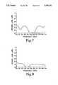
- FIG. 7is a graph illustrating the performance of the transducer illustrated in FIG. 6 without the improvement of the present invention.
- FIG. 8is a graph illustrating the performance of the transducer illustrated in FIG. 6 including the improvement of the invention.
- FIGS. 3 and 4illustrate a transducer 20 embodying the present invention including elements which are common to those illustrated in FIGS. 1 and 2 and are designated by the same reference numerals.
- the piston 18is replaced by a piston 22 having an inner end which constitutes a stepped wall 24.
- the end portion 14a of the center conductor 14protrudes into the waveguide 10 in a transverse direction as indicated by an arrow 26.
- the stepped wall 24 of the piston 22is formed with three steps 24a, 24b and 24c which protrude axially into the waveguide 10 by different distances.
- the axial directionis indicated by an arrow 28.
- the step 24bprotrudes into the waveguide 10 in the axial direction 28 further than the step 24a
- the step 24cprotrudes further into the waveguide 10 than the step 24b.
- the steps 24a, 24b and 24ceach different distance corresponding to L.
- the distance between the step 24a and the center of the end portion 14ais designated as L1
- the corresponding distances for the steps 24b and 24cbeing designated as L2 and L3 respectively.
- FIG. 5illustrates another transducer 30 embodying the present invention in which the piston 22 is inverted such that the steps 24a, 24b and 24c of the stepped wall 24 protrude into the waveguide 10 by progressively increasing distances in the transverse direction.
- the scientific principle by which the stepped end wall 24 improves the matching and bandwidth of the coaxial-to-waveguide transitionis not fully understood, and the phenomenon itself was discovered experimentally.
- the scope of the inventionincludes providing the stepped wall 24 with two or more steps which protrude axially into the waveguide 10 by different distances.
- the variables involvedare extremely complex, and the particular number, arrangement, and dimensions of the steps are determined most efficiently in actual practice by empirical procedures.
- FIG. 6illustrates a coaxial-to-waveguide transducer 40 which was constructed and tested in accordance with the present invention.
- the transducer 40includes an elongated tubular waveguide 42 having a main transmission section 42a which is connected to a step transformer section 42b at 42c by brazing or the like.
- a transducer section 42dcommunicates with the end of the transformer section 42b opposite the transmission section 42a.
- An end portion 44a of a center conductor 44 of a coaxial cable 46protrudes transversely into the transducer section 42d through a hole 42e in the manner described above.
- the cable 46is joined to the transducer section 42d by a conventional connector which is not shown in the drawing.
- a ceramic dome window 48is fitted over the end portion 44a to hermetically isolate the coaxial cable 46 from the interior of the waveguide 42.
- a piston 50is slidingly fitted into the right end of the transducer section 42d as viewed in FIG. 6, and has an inner end which constitutes a stepped end wall 52 of the waveguide 42.
- the step transformer section 42bis provided to match the characteristic impedance of the coaxial cable 46, which is conventionally 50 ohms, to that of the main transmission section 42a of the waveguide 42, which in the present example is 120 ohms.
- Step transformersare known in the art per se, as described in an article entitled "Optimum Design of Stepped Transmission-Line Transformers", by S. Cohn, in I.R.E. Transactions--Microwave Theory and Techniques, Apr. 1955, pp. 16-21.
- the wall 52is formed with a step 52a, and a step 52b which protrudes axially into the waveguide 42 further than the step 52a.
- the height K of the step 52bwas 23 mm.
- the distance L1 from the step 52a to the center of the end portion 44a of the center conductor 44was 57 mm.
- the distance L2 from the step 52b to the center of the end portion 44awas 38 mm.
- the height Hwas 102 mm
- the distance hwas 37 mm
- the width W(not illustrated) was 229 mm
- the diameter 2a of the center conductor 44was 13 mm
- the diameter 2b of the hole 42ewas 64 mm.
- the height of the inner cross-section H1 of the transmission section 42a of the waveguide 42was 36 mm.
- the step transformer section 42bhad two intermediate steps with inner cross-section heights H2 and H3 of 47 mm and 78 mm respectively.
- the transducer 40 with these dimensionswas designed to operate at a center frequency of 10.5 GHz.
- FIG. 7illustrates the performance of the transducer 40 with the piston 50 replaced by a piston (not shown) having a flat inner end as in the prior art illustrated in FIG. 1 located at a distance L of 57 mm (equal to L1 in FIG. 6) from the center of the end portion 44a. It will be seen in FIG. 7 that the return loss was never better than -20 dB over the entire frequency range of 10 to 11 GHz.
- FIG. 8illustrates the performance of the transducer 40 incorporating the stepped piston 50 as described with reference to FIG. 6. It will be seen in FIG. 8 that the return loss has been reduced by a factor of 5 dB over the frequency range of 10 to 11 GHz as compared with FIG. 7, thereby extending the usable bandwidth of the transition.
- the inventionhas been described and illustrated as being applied to a transducer in which the inner conductor projects as a probe only part way into the waveguide, the principle of the invention may be applied to transducers using other types of coupling.
- the inner and outer conductors of the coaxial linemay contact opposite walls of the waveguide, or the inner conductor may connect to a coupling loop inside the waveguide.
Landscapes
- Microwave Tubes (AREA)
Abstract
Description
Claims (12)
Priority Applications (1)
| Application Number | Priority Date | Filing Date | Title |
|---|---|---|---|
| US07/714,550US5148131A (en) | 1991-06-11 | 1991-06-11 | Coaxial-to-waveguide transducer with improved matching |
Applications Claiming Priority (1)
| Application Number | Priority Date | Filing Date | Title |
|---|---|---|---|
| US07/714,550US5148131A (en) | 1991-06-11 | 1991-06-11 | Coaxial-to-waveguide transducer with improved matching |
Publications (1)
| Publication Number | Publication Date |
|---|---|
| US5148131Atrue US5148131A (en) | 1992-09-15 |
Family
ID=24870479
Family Applications (1)
| Application Number | Title | Priority Date | Filing Date |
|---|---|---|---|
| US07/714,550Expired - LifetimeUS5148131A (en) | 1991-06-11 | 1991-06-11 | Coaxial-to-waveguide transducer with improved matching |
Country Status (1)
| Country | Link |
|---|---|
| US (1) | US5148131A (en) |
Cited By (31)
| Publication number | Priority date | Publication date | Assignee | Title |
|---|---|---|---|---|
| US5276410A (en)* | 1991-06-14 | 1994-01-04 | Sony Corporation | Circular to linear polarization converter |
| US5359339A (en)* | 1993-07-16 | 1994-10-25 | Martin Marietta Corporation | Broadband short-horn antenna |
| US5418428A (en)* | 1991-12-13 | 1995-05-23 | Goldstar Co., Ltd. | Waveguide system with support for magnetrons |
| US5838212A (en)* | 1996-01-11 | 1998-11-17 | Eev Limited | High frequency transition arrangement |
| GB2398178A (en)* | 2003-02-05 | 2004-08-11 | Smiths Group Plc | Microwave transitions and antennas |
| US7161363B2 (en) | 2002-05-23 | 2007-01-09 | Cascade Microtech, Inc. | Probe for testing a device under test |
| US20070063791A1 (en)* | 2004-02-06 | 2007-03-22 | L-3 Communications Corporation | Radial power divider/combiner using waveguide impedance transformers |
| US7233160B2 (en) | 2000-12-04 | 2007-06-19 | Cascade Microtech, Inc. | Wafer probe |
| US7271603B2 (en) | 2003-05-23 | 2007-09-18 | Cascade Microtech, Inc. | Shielded probe for testing a device under test |
| US7285969B2 (en) | 2002-11-13 | 2007-10-23 | Cascade Microtech, Inc. | Probe for combined signals |
| US7352258B2 (en)* | 2002-03-28 | 2008-04-01 | Cascade Microtech, Inc. | Waveguide adapter for probe assembly having a detachable bias tee |
| US7403028B2 (en) | 2006-06-12 | 2008-07-22 | Cascade Microtech, Inc. | Test structure and probe for differential signals |
| US7420381B2 (en) | 2004-09-13 | 2008-09-02 | Cascade Microtech, Inc. | Double sided probing structures |
| US7427868B2 (en) | 2003-12-24 | 2008-09-23 | Cascade Microtech, Inc. | Active wafer probe |
| US7443186B2 (en) | 2006-06-12 | 2008-10-28 | Cascade Microtech, Inc. | On-wafer test structures for differential signals |
| US7449899B2 (en) | 2005-06-08 | 2008-11-11 | Cascade Microtech, Inc. | Probe for high frequency signals |
| US20080303612A1 (en)* | 2007-06-07 | 2008-12-11 | Microelectronics Technology Inc. | Waveguide structure |
| US7504842B2 (en) | 1997-05-28 | 2009-03-17 | Cascade Microtech, Inc. | Probe holder for testing of a test device |
| US7535247B2 (en) | 2005-01-31 | 2009-05-19 | Cascade Microtech, Inc. | Interface for testing semiconductors |
| US7609077B2 (en) | 2006-06-09 | 2009-10-27 | Cascade Microtech, Inc. | Differential signal probe with integral balun |
| US7619419B2 (en) | 2005-06-13 | 2009-11-17 | Cascade Microtech, Inc. | Wideband active-passive differential signal probe |
| US7656172B2 (en) | 2005-01-31 | 2010-02-02 | Cascade Microtech, Inc. | System for testing semiconductors |
| US7723999B2 (en) | 2006-06-12 | 2010-05-25 | Cascade Microtech, Inc. | Calibration structures for differential signal probing |
| US7764072B2 (en) | 2006-06-12 | 2010-07-27 | Cascade Microtech, Inc. | Differential signal probing system |
| FR2944916A1 (en)* | 2009-04-28 | 2010-10-29 | Thales Sa | Device for transition between wave guide and connector e.g. microstrip line in field of antenna, has impedance matching step enabling radioelectric performances of device to depend on machining precision and positioning precision |
| US7876114B2 (en) | 2007-08-08 | 2011-01-25 | Cascade Microtech, Inc. | Differential waveguide probe |
| CN105762476A (en)* | 2016-04-12 | 2016-07-13 | 深圳市华讯方舟卫星通信有限公司 | Radial waveguide combiner/divider |
| JP2017017638A (en)* | 2015-07-06 | 2017-01-19 | 三菱電機株式会社 | Directional coupler |
| RU189258U1 (en)* | 2019-03-06 | 2019-05-17 | Акционерное общество "Научно-исследовательский институт Приборостроения имени В.В. Тихомирова" | Coaxial waveguide transition |
| RU2735360C1 (en)* | 2020-02-04 | 2020-10-30 | Акционерное общество "Научно-производственное предприятие "Пульсар" | Coaxial-waveguide broadband junction |
| CN114709582A (en)* | 2022-04-22 | 2022-07-05 | 江苏俊知技术有限公司 | Ka-band Orthogonal Waveguide Coaxial Converter with Height Reduction Transition and Assembly Method |
Citations (6)
| Publication number | Priority date | Publication date | Assignee | Title |
|---|---|---|---|---|
| US2588103A (en)* | 1946-09-14 | 1952-03-04 | Bell Telephone Labor Inc | Wave guide coupling between coaxial lines |
| US2829352A (en)* | 1953-12-24 | 1958-04-01 | Varian Associates | Tunable waveguide short |
| US3478282A (en)* | 1965-04-15 | 1969-11-11 | Cossor Ltd A C | Couplings between waveguides and coaxial lines |
| US4139828A (en)* | 1976-07-20 | 1979-02-13 | Thomson-Csf | Transition device between a coaxial line and a wave-guide |
| US4740764A (en)* | 1987-06-03 | 1988-04-26 | Varian Associates, Inc. | Pressure sealed waveguide to coaxial line connection |
| US5004990A (en)* | 1988-11-15 | 1991-04-02 | Thomson Tubes Electroniques | Microwave load in small-length oversized waveguide form |
- 1991
- 1991-06-11USUS07/714,550patent/US5148131A/ennot_activeExpired - Lifetime
Patent Citations (6)
| Publication number | Priority date | Publication date | Assignee | Title |
|---|---|---|---|---|
| US2588103A (en)* | 1946-09-14 | 1952-03-04 | Bell Telephone Labor Inc | Wave guide coupling between coaxial lines |
| US2829352A (en)* | 1953-12-24 | 1958-04-01 | Varian Associates | Tunable waveguide short |
| US3478282A (en)* | 1965-04-15 | 1969-11-11 | Cossor Ltd A C | Couplings between waveguides and coaxial lines |
| US4139828A (en)* | 1976-07-20 | 1979-02-13 | Thomson-Csf | Transition device between a coaxial line and a wave-guide |
| US4740764A (en)* | 1987-06-03 | 1988-04-26 | Varian Associates, Inc. | Pressure sealed waveguide to coaxial line connection |
| US5004990A (en)* | 1988-11-15 | 1991-04-02 | Thomson Tubes Electroniques | Microwave load in small-length oversized waveguide form |
Cited By (57)
| Publication number | Priority date | Publication date | Assignee | Title |
|---|---|---|---|---|
| US5276410A (en)* | 1991-06-14 | 1994-01-04 | Sony Corporation | Circular to linear polarization converter |
| US5418428A (en)* | 1991-12-13 | 1995-05-23 | Goldstar Co., Ltd. | Waveguide system with support for magnetrons |
| US5359339A (en)* | 1993-07-16 | 1994-10-25 | Martin Marietta Corporation | Broadband short-horn antenna |
| US5838212A (en)* | 1996-01-11 | 1998-11-17 | Eev Limited | High frequency transition arrangement |
| US7504842B2 (en) | 1997-05-28 | 2009-03-17 | Cascade Microtech, Inc. | Probe holder for testing of a test device |
| US7761983B2 (en) | 2000-12-04 | 2010-07-27 | Cascade Microtech, Inc. | Method of assembling a wafer probe |
| US7688097B2 (en) | 2000-12-04 | 2010-03-30 | Cascade Microtech, Inc. | Wafer probe |
| US7495461B2 (en) | 2000-12-04 | 2009-02-24 | Cascade Microtech, Inc. | Wafer probe |
| US7456646B2 (en) | 2000-12-04 | 2008-11-25 | Cascade Microtech, Inc. | Wafer probe |
| US7233160B2 (en) | 2000-12-04 | 2007-06-19 | Cascade Microtech, Inc. | Wafer probe |
| US7352258B2 (en)* | 2002-03-28 | 2008-04-01 | Cascade Microtech, Inc. | Waveguide adapter for probe assembly having a detachable bias tee |
| US7489149B2 (en) | 2002-05-23 | 2009-02-10 | Cascade Microtech, Inc. | Shielded probe for testing a device under test |
| US7436194B2 (en) | 2002-05-23 | 2008-10-14 | Cascade Microtech, Inc. | Shielded probe with low contact resistance for testing a device under test |
| US7304488B2 (en) | 2002-05-23 | 2007-12-04 | Cascade Microtech, Inc. | Shielded probe for high-frequency testing of a device under test |
| US7161363B2 (en) | 2002-05-23 | 2007-01-09 | Cascade Microtech, Inc. | Probe for testing a device under test |
| US7482823B2 (en) | 2002-05-23 | 2009-01-27 | Cascade Microtech, Inc. | Shielded probe for testing a device under test |
| US7518387B2 (en) | 2002-05-23 | 2009-04-14 | Cascade Microtech, Inc. | Shielded probe for testing a device under test |
| US7417446B2 (en) | 2002-11-13 | 2008-08-26 | Cascade Microtech, Inc. | Probe for combined signals |
| US7453276B2 (en) | 2002-11-13 | 2008-11-18 | Cascade Microtech, Inc. | Probe for combined signals |
| US7285969B2 (en) | 2002-11-13 | 2007-10-23 | Cascade Microtech, Inc. | Probe for combined signals |
| GB2398178A (en)* | 2003-02-05 | 2004-08-11 | Smiths Group Plc | Microwave transitions and antennas |
| US20040183620A1 (en)* | 2003-02-05 | 2004-09-23 | Smiths Group Plc | Microwave transitions and antennas |
| GB2398178B (en)* | 2003-02-05 | 2006-03-22 | Smiths Group Plc | Microwave transitions and antennas |
| US7030826B2 (en) | 2003-02-05 | 2006-04-18 | Smiths Group Plc | Microwave transition plate for antennas with a radiating slot face |
| US7501842B2 (en) | 2003-05-23 | 2009-03-10 | Cascade Microtech, Inc. | Shielded probe for testing a device under test |
| US7898273B2 (en) | 2003-05-23 | 2011-03-01 | Cascade Microtech, Inc. | Probe for testing a device under test |
| US7271603B2 (en) | 2003-05-23 | 2007-09-18 | Cascade Microtech, Inc. | Shielded probe for testing a device under test |
| US7498829B2 (en) | 2003-05-23 | 2009-03-03 | Cascade Microtech, Inc. | Shielded probe for testing a device under test |
| US7427868B2 (en) | 2003-12-24 | 2008-09-23 | Cascade Microtech, Inc. | Active wafer probe |
| US7759953B2 (en) | 2003-12-24 | 2010-07-20 | Cascade Microtech, Inc. | Active wafer probe |
| US20070063791A1 (en)* | 2004-02-06 | 2007-03-22 | L-3 Communications Corporation | Radial power divider/combiner using waveguide impedance transformers |
| US7482894B2 (en)* | 2004-02-06 | 2009-01-27 | L-3 Communications Corporation | Radial power divider/combiner using waveguide impedance transformers |
| US7420381B2 (en) | 2004-09-13 | 2008-09-02 | Cascade Microtech, Inc. | Double sided probing structures |
| US8013623B2 (en) | 2004-09-13 | 2011-09-06 | Cascade Microtech, Inc. | Double sided probing structures |
| US7940069B2 (en) | 2005-01-31 | 2011-05-10 | Cascade Microtech, Inc. | System for testing semiconductors |
| US7535247B2 (en) | 2005-01-31 | 2009-05-19 | Cascade Microtech, Inc. | Interface for testing semiconductors |
| US7898281B2 (en) | 2005-01-31 | 2011-03-01 | Cascade Mircotech, Inc. | Interface for testing semiconductors |
| US7656172B2 (en) | 2005-01-31 | 2010-02-02 | Cascade Microtech, Inc. | System for testing semiconductors |
| US7449899B2 (en) | 2005-06-08 | 2008-11-11 | Cascade Microtech, Inc. | Probe for high frequency signals |
| US7619419B2 (en) | 2005-06-13 | 2009-11-17 | Cascade Microtech, Inc. | Wideband active-passive differential signal probe |
| US7609077B2 (en) | 2006-06-09 | 2009-10-27 | Cascade Microtech, Inc. | Differential signal probe with integral balun |
| US7443186B2 (en) | 2006-06-12 | 2008-10-28 | Cascade Microtech, Inc. | On-wafer test structures for differential signals |
| US7764072B2 (en) | 2006-06-12 | 2010-07-27 | Cascade Microtech, Inc. | Differential signal probing system |
| US7750652B2 (en) | 2006-06-12 | 2010-07-06 | Cascade Microtech, Inc. | Test structure and probe for differential signals |
| US7723999B2 (en) | 2006-06-12 | 2010-05-25 | Cascade Microtech, Inc. | Calibration structures for differential signal probing |
| US7403028B2 (en) | 2006-06-12 | 2008-07-22 | Cascade Microtech, Inc. | Test structure and probe for differential signals |
| US20080303612A1 (en)* | 2007-06-07 | 2008-12-11 | Microelectronics Technology Inc. | Waveguide structure |
| US7876114B2 (en) | 2007-08-08 | 2011-01-25 | Cascade Microtech, Inc. | Differential waveguide probe |
| FR2944916A1 (en)* | 2009-04-28 | 2010-10-29 | Thales Sa | Device for transition between wave guide and connector e.g. microstrip line in field of antenna, has impedance matching step enabling radioelectric performances of device to depend on machining precision and positioning precision |
| JP2017017638A (en)* | 2015-07-06 | 2017-01-19 | 三菱電機株式会社 | Directional coupler |
| CN105762476A (en)* | 2016-04-12 | 2016-07-13 | 深圳市华讯方舟卫星通信有限公司 | Radial waveguide combiner/divider |
| WO2017177577A1 (en)* | 2016-04-12 | 2017-10-19 | 深圳市华讯方舟卫星通信有限公司 | Radial waveguide combiner/divider |
| CN105762476B (en)* | 2016-04-12 | 2018-01-16 | 深圳市华讯方舟卫星通信有限公司 | Radial waveguide combiner/divider |
| RU189258U1 (en)* | 2019-03-06 | 2019-05-17 | Акционерное общество "Научно-исследовательский институт Приборостроения имени В.В. Тихомирова" | Coaxial waveguide transition |
| RU2735360C1 (en)* | 2020-02-04 | 2020-10-30 | Акционерное общество "Научно-производственное предприятие "Пульсар" | Coaxial-waveguide broadband junction |
| CN114709582A (en)* | 2022-04-22 | 2022-07-05 | 江苏俊知技术有限公司 | Ka-band Orthogonal Waveguide Coaxial Converter with Height Reduction Transition and Assembly Method |
| CN114709582B (en)* | 2022-04-22 | 2024-06-04 | 江苏俊知技术有限公司 | Ka-band orthogonal waveguide coaxial converter with height-reducing transition and assembly method |
Similar Documents
| Publication | Publication Date | Title |
|---|---|---|
| US5148131A (en) | Coaxial-to-waveguide transducer with improved matching | |
| US4651115A (en) | Waveguide-to-microstrip transition | |
| US5424694A (en) | Miniature directional coupler | |
| US4553112A (en) | Overmoded tapered waveguide transition having phase shifted higher order mode cancellation | |
| US5331332A (en) | Waveguide coupling structure | |
| US4498061A (en) | Microwave receiving device | |
| JP2800636B2 (en) | Flexible waveguide | |
| US6002305A (en) | Transition between circuit transmission line and microwave waveguide | |
| US5600286A (en) | End-on transmission line-to-waveguide transition | |
| US7332982B2 (en) | Waveguide diplexer of electric plane T-junction structure with resonant iris | |
| EP0458226A2 (en) | Orthomode transducer between a circular waveguide and a coaxial cable | |
| US5406234A (en) | Tunable microwave filter apparatus having a notch resonator | |
| US4138625A (en) | Helix type travelling-wave tube amplifier | |
| US4184130A (en) | Filter devices incorporating dielectric resonators and leakage cable | |
| US4313097A (en) | Image frequency reflection mode filter for use in a high-frequency receiver | |
| GB2313714A (en) | Waveguide hybrid junction | |
| US4458217A (en) | Slot-coupled microwave diplexer and coupler therefor | |
| US4939484A (en) | Transmission channel coupler for antenna | |
| JPH0746011A (en) | Power distributor | |
| JP2008079085A (en) | Transmission line waveguide converter | |
| US5105174A (en) | Wave-guide band rejection filter having a short circuited coaxial tuning screw | |
| US5812032A (en) | Stripline transition for twin toroid phase shifter | |
| US6249195B1 (en) | Dielectric filter, dielectric duplexer, and transceiver having circular and polygonal electrode openings | |
| US4633205A (en) | Loop coupled YIG resonator | |
| US5691672A (en) | Magnetic coupling device between a TEM line main conductor and a waveguide forming a λg/2 resonator |
Legal Events
| Date | Code | Title | Description |
|---|---|---|---|
| AS | Assignment | Owner name:HUGHES AIRCRAFT COMPANY, CALIFORNIA Free format text:ASSIGNMENT OF ASSIGNORS INTEREST.;ASSIGNORS:AMBOSS, KURT;HART, STEPHEN L.;REEL/FRAME:005742/0935 Effective date:19910604 | |
| STCF | Information on status: patent grant | Free format text:PATENTED CASE | |
| FEPP | Fee payment procedure | Free format text:PAYOR NUMBER ASSIGNED (ORIGINAL EVENT CODE: ASPN); ENTITY STATUS OF PATENT OWNER: LARGE ENTITY | |
| FPAY | Fee payment | Year of fee payment:4 | |
| AS | Assignment | Owner name:HUGHES ELECTRONICS CORPORATION, CALIFORNIA Free format text:ASSIGNMENT OF ASSIGNORS INTEREST;ASSIGNOR:HE HOLDINGS INC., HUGHES ELECTRONICS, FORMERLY KNOWN AS HUGHES AIRCRAFT COMPANY;REEL/FRAME:009123/0473 Effective date:19971216 | |
| FPAY | Fee payment | Year of fee payment:8 | |
| FEPP | Fee payment procedure | Free format text:PAYER NUMBER DE-ASSIGNED (ORIGINAL EVENT CODE: RMPN); ENTITY STATUS OF PATENT OWNER: LARGE ENTITY Free format text:PAYOR NUMBER ASSIGNED (ORIGINAL EVENT CODE: ASPN); ENTITY STATUS OF PATENT OWNER: LARGE ENTITY | |
| FPAY | Fee payment | Year of fee payment:12 | |
| AS | Assignment | Owner name:BOEING COMPANY, THE, ILLINOIS Free format text:ASSIGNMENT OF ASSIGNORS INTEREST;ASSIGNOR:HUGHES ELECTRONICS CORPORATION;REEL/FRAME:015428/0184 Effective date:20000905 | |
| AS | Assignment | Owner name:BOEING ELECTRON DYNAMIC DEVICES, INC., CALIFORNIA Free format text:ASSIGNMENT OF ASSIGNORS INTEREST;ASSIGNOR:THE BOEING COMPANY;REEL/FRAME:017649/0130 Effective date:20050228 | |
| AS | Assignment | Owner name:L-3 COMMUNICATIONS ELECTRON TECHNOLOGIES, INC., CA Free format text:CHANGE OF NAME;ASSIGNOR:BOEING ELECTRON DYNAMIC DEVICES, INC.;REEL/FRAME:017706/0155 Effective date:20050228 |