US5147685A - Padding device - Google Patents
Padding deviceDownload PDFInfo
- Publication number
- US5147685A US5147685AUS07/657,489US65748991AUS5147685AUS 5147685 AUS5147685 AUS 5147685AUS 65748991 AUS65748991 AUS 65748991AUS 5147685 AUS5147685 AUS 5147685A
- Authority
- US
- United States
- Prior art keywords
- flowable material
- foam
- compression set
- padding
- padding device
- Prior art date
- Legal status (The legal status is an assumption and is not a legal conclusion. Google has not performed a legal analysis and makes no representation as to the accuracy of the status listed.)
- Expired - Fee Related
Links
- 239000000463materialSubstances0.000claimsabstractdescription109
- 230000009969flowable effectEffects0.000claimsabstractdescription92
- 239000006260foamSubstances0.000claimsabstractdescription50
- 230000006835compressionEffects0.000claimsabstractdescription35
- 238000007906compressionMethods0.000claimsabstractdescription35
- 230000004044responseEffects0.000claimsdescription10
- 230000001788irregularEffects0.000claimsdescription6
- 238000000034methodMethods0.000abstractdescription6
- 239000002245particleSubstances0.000abstractdescription3
- 239000010410layerSubstances0.000description39
- 230000004888barrier functionEffects0.000description16
- 230000008901benefitEffects0.000description13
- 230000005012migrationEffects0.000description9
- 238000013508migrationMethods0.000description9
- 238000013461designMethods0.000description8
- 239000007788liquidSubstances0.000description7
- 239000004744fabricSubstances0.000description6
- XLYOFNOQVPJJNP-UHFFFAOYSA-NwaterSubstancesOXLYOFNOQVPJJNP-UHFFFAOYSA-N0.000description6
- 239000007789gasSubstances0.000description4
- 230000007423decreaseEffects0.000description3
- 239000013536elastomeric materialSubstances0.000description3
- 229920001821foam rubberPolymers0.000description3
- 230000009974thixotropic effectEffects0.000description3
- 238000009825accumulationMethods0.000description2
- 230000006978adaptationEffects0.000description2
- 210000003484anatomyAnatomy0.000description2
- 210000000988bone and boneAnatomy0.000description2
- 230000001010compromised effectEffects0.000description2
- 230000007812deficiencyEffects0.000description2
- 235000019589hardnessNutrition0.000description2
- 230000006872improvementEffects0.000description2
- 238000012986modificationMethods0.000description2
- 230000004048modificationEffects0.000description2
- 238000004806packaging method and processMethods0.000description2
- 229920002635polyurethanePolymers0.000description2
- 239000004814polyurethaneSubstances0.000description2
- 239000012858resilient materialSubstances0.000description2
- 239000011343solid materialSubstances0.000description2
- 239000004698PolyethyleneSubstances0.000description1
- 229920002334SpandexPolymers0.000description1
- 230000009471actionEffects0.000description1
- 210000003423ankleAnatomy0.000description1
- 230000001413cellular effectEffects0.000description1
- 239000000919ceramicSubstances0.000description1
- 230000000295complement effectEffects0.000description1
- 230000003247decreasing effectEffects0.000description1
- 230000000694effectsEffects0.000description1
- 229920001971elastomerPolymers0.000description1
- 210000002683footAnatomy0.000description1
- 239000000499gelSubstances0.000description1
- 239000011325microbeadSubstances0.000description1
- 210000003049pelvic boneAnatomy0.000description1
- -1polyethylenePolymers0.000description1
- 229920000573polyethylenePolymers0.000description1
- 229920000098polyolefinPolymers0.000description1
- 238000005096rolling processMethods0.000description1
- 238000009958sewingMethods0.000description1
- 239000002356single layerSubstances0.000description1
- 239000004759spandexSubstances0.000description1
- 238000007655standard test methodMethods0.000description1
- 238000012360testing methodMethods0.000description1
- 210000001519tissueAnatomy0.000description1
- 125000000391vinyl groupChemical group[H]C([*])=C([H])[H]0.000description1
- 229920002554vinyl polymerPolymers0.000description1
Images


Classifications
- B—PERFORMING OPERATIONS; TRANSPORTING
- B62—LAND VEHICLES FOR TRAVELLING OTHERWISE THAN ON RAILS
- B62J—CYCLE SADDLES OR SEATS; AUXILIARY DEVICES OR ACCESSORIES SPECIALLY ADAPTED TO CYCLES AND NOT OTHERWISE PROVIDED FOR, e.g. ARTICLE CARRIERS OR CYCLE PROTECTORS
- B62J1/00—Saddles or other seats for cycles; Arrangement thereof; Component parts
- B62J1/18—Covers for saddles or other seats; Paddings
- Y—GENERAL TAGGING OF NEW TECHNOLOGICAL DEVELOPMENTS; GENERAL TAGGING OF CROSS-SECTIONAL TECHNOLOGIES SPANNING OVER SEVERAL SECTIONS OF THE IPC; TECHNICAL SUBJECTS COVERED BY FORMER USPC CROSS-REFERENCE ART COLLECTIONS [XRACs] AND DIGESTS
- Y10—TECHNICAL SUBJECTS COVERED BY FORMER USPC
- Y10S—TECHNICAL SUBJECTS COVERED BY FORMER USPC CROSS-REFERENCE ART COLLECTIONS [XRACs] AND DIGESTS
- Y10S5/00—Beds
- Y10S5/909—Flowable viscous, e.g. gel material containing
- Y—GENERAL TAGGING OF NEW TECHNOLOGICAL DEVELOPMENTS; GENERAL TAGGING OF CROSS-SECTIONAL TECHNOLOGIES SPANNING OVER SEVERAL SECTIONS OF THE IPC; TECHNICAL SUBJECTS COVERED BY FORMER USPC CROSS-REFERENCE ART COLLECTIONS [XRACs] AND DIGESTS
- Y10—TECHNICAL SUBJECTS COVERED BY FORMER USPC
- Y10T—TECHNICAL SUBJECTS COVERED BY FORMER US CLASSIFICATION
- Y10T428/00—Stock material or miscellaneous articles
- Y10T428/23—Sheet including cover or casing
- Y10T428/233—Foamed or expanded material encased
- Y—GENERAL TAGGING OF NEW TECHNOLOGICAL DEVELOPMENTS; GENERAL TAGGING OF CROSS-SECTIONAL TECHNOLOGIES SPANNING OVER SEVERAL SECTIONS OF THE IPC; TECHNICAL SUBJECTS COVERED BY FORMER USPC CROSS-REFERENCE ART COLLECTIONS [XRACs] AND DIGESTS
- Y10—TECHNICAL SUBJECTS COVERED BY FORMER USPC
- Y10T—TECHNICAL SUBJECTS COVERED BY FORMER US CLASSIFICATION
- Y10T428/00—Stock material or miscellaneous articles
- Y10T428/23—Sheet including cover or casing
- Y10T428/234—Sheet including cover or casing including elements cooperating to form cells
- Y—GENERAL TAGGING OF NEW TECHNOLOGICAL DEVELOPMENTS; GENERAL TAGGING OF CROSS-SECTIONAL TECHNOLOGIES SPANNING OVER SEVERAL SECTIONS OF THE IPC; TECHNICAL SUBJECTS COVERED BY FORMER USPC CROSS-REFERENCE ART COLLECTIONS [XRACs] AND DIGESTS
- Y10—TECHNICAL SUBJECTS COVERED BY FORMER USPC
- Y10T—TECHNICAL SUBJECTS COVERED BY FORMER US CLASSIFICATION
- Y10T428/00—Stock material or miscellaneous articles
- Y10T428/24—Structurally defined web or sheet [e.g., overall dimension, etc.]
- Y10T428/24752—Laterally noncoextensive components
- Y—GENERAL TAGGING OF NEW TECHNOLOGICAL DEVELOPMENTS; GENERAL TAGGING OF CROSS-SECTIONAL TECHNOLOGIES SPANNING OVER SEVERAL SECTIONS OF THE IPC; TECHNICAL SUBJECTS COVERED BY FORMER USPC CROSS-REFERENCE ART COLLECTIONS [XRACs] AND DIGESTS
- Y10—TECHNICAL SUBJECTS COVERED BY FORMER USPC
- Y10T—TECHNICAL SUBJECTS COVERED BY FORMER US CLASSIFICATION
- Y10T428/00—Stock material or miscellaneous articles
- Y10T428/249921—Web or sheet containing structurally defined element or component
- Y10T428/249953—Composite having voids in a component [e.g., porous, cellular, etc.]
- Y10T428/249987—With nonvoid component of specified composition
Definitions
- This inventionrelates generally to the field of padding devices, and in particular, to padding devices used on seats such as bicycle seats.
- padding deviceshave been employed in the past. Examples include liquid- or gas-filled bladders, e.g. water-filled cushions and pneumatic pads; and gases or liquids dispersed in a solid material, e.g. foams and gels.
- such padding devicesoperate on the principle of conformation to the shape of an object when placed under pressure. When a force, such as a person's mass, is placed on such a padding device, the device deforms so as to conform to the shape of the pressure applying object in order to distribute the force over as large an area as possible.
- These devicesperform adequately when the object being padded has a relatively large, uniformly shaped surface area.
- the prior art padding devicesoften do not perform adequately. This is because the padding devices exert greater pressure on the area of concentrated force.
- the reason for the greater pressureis that the prior art padding devices deform by compressing. Therefore, a sharp protuberance would compress the padding device more than the surrounding areas and, as a result, the padding device presses back with greater force in these areas.
- Such areas of high pressureare especially undesirable when the protuberance is a bone, such as an ankle or ischial tuberosity. The high pressure can lead to discomfort and, after periods of extended use, to actual damage to the tissue overlying the protruding bone.
- a padding devicecomprising a gas dispersed in a solid material, e.g. foam.
- Tiny gas bubbles in foamact like millions of coil "springs".
- the "springs”When required to conform to an irregular shape, such as a human body, the "springs" are compressed to varying degrees, each pushing back on the body with a force proportional to the amount of compression. Intimate conformity is best obtained with a relatively soft foam, which can be compared to weak "springs".
- the pressure on protuberances, where the "springs" are greatly compressed,will be relatively high, possibly causing pain and reduced circulation. The problem is even more pronounced if a stiffer foam is employed and the "springs" are stronger.
- the flowable, pressure-compensating materials disclosed in the above-mentioned patentsare typically placed in a pliable package, such as between two leak-proof resinous sheets which are sealed at the edges.
- the flowable materialsact hydraulically. An applied force causes flowable material to migrate from areas of higher pressure to areas of lower pressure until pressure throughout the package is uniform. Once conformity has been achieved, force is distributed substantially equally over the entire surface of the package thus alleviating the differential pressure problems associated with prior devices.
- the viscosity of the flowable materialcan be varied. Higher viscosity does not decrease the ability of the flowable material to conform to the shape of the pressure applying object, only the speed at which it will migrate to conform.
- Flowable materialsare presently sold under the registered trademark FLOLITE (TM).
- Bicycle seatsmust be of relatively small size so that the seat itself does not interfere with the pedaling action of the rider's legs. Therefore, the rider's weight is concentrated over a relatively small area. This weight is further concentrated on the rider's ischial tuberosities. Additionally, the weight of the seat should preferably be held to a minimum.
- U.S. Pat. No. 4,504,089 by Calvert et al.discloses a liquid cushioned bicycle seat having separate forward and rear compartments.
- the forward pommel compartmenthas a longitudinal baffle to restrict side-to-side flow of the cushioning liquid.
- the rear saddle compartmenthas two side sections separated by a barrier which tapers towards the rear. The barrier terminates before reaching the rearward end of the saddle, thereby providing an opening connecting the side sections which permits side-to-side flow of the cushioning liquid.
- the pressure exerted on the first and second side sectionscyclically increases and decreases within each section as the bicycle is pedaled.
- the rear openingserves as a baffle to control the direction and movement of cushioning liquid from one section to the other upon compression caused by pedaling.
- the liquid cushioning media disclosed by Calvert et al.is preferably water. Due to water's low viscosity, it conforms to the shape of a pressure applying object almost instantaneously. Logically, it would appear that water would be an excellent cushioning material because of its capability to instantaneously flow to achieve conformability. However, incompressible materials which provide almost instantaneous conformability do not provide as much control and stability as padding materials which do not respond to instantaneously applied pressure.
- Monter who has attempted to sit on a waterbedis familiar with the lack of stability associated with water cushioned devices.
- the compartmentscan be filled with foam rubber or a thixotropic or dilatant material.
- the thixotropic or dilatant materialis defined as having a yield point of at least 4 grams per square centimeter and a viscosity between about 100,000 poise and about 40,000 poise at 0° F. and 80° F. This definition describes materials which are includable in the group of flowable, pressure-compensating materials described hereinbefore.
- the thickness of the paddingis kept to a minimum and it is designed to conform to the pelvic configuration of the user and to retain that shape.
- the padding materialis a pressurized foam rubber which is injected in the compartments while the user is seated on the bike seat.
- the foam rubber materialis claimed to have a viscosity substantially lower than the thixotropic or dilatant material.
- the covercan be clipped to a bike seat by clipping the rear end and using an elastic to secure the front end.
- the bicycle seat covers disclosed in the two Jacobs patentsinclude the use of flowable materials in a compartmentalized manner
- the designs disclosed thereinsuffer from a number of disadvantages.
- the compartmentalized containment of the flowable material in relatively thin layers of small areacan help reduce bottoming out of sharp protuberances, it also limits the conformability of the flowable material over broader areas. In other words, as the area of the flowable material compartment decreases, the ability to conform to various shapes is reduced.
- Another disadvantage of the Jacobs designis the inability of the flowable material in the rear portion of the seat to flow from one side of the seat to the other. This prevents the seat from adjusting to anatomical differences between different riders, or asymmetries of a single rider, e.g.
- the cushioning materialis capable of traveling down the center portion of the seat. As a result, if a rider rides forward on the seat, the pressure applied to the forward portion forces cushioning material towards the rear central portion. As can be appreciated, an excess of cushioning material in this area of the seat would be uncomfortable over periods of even short duration.
- the padcan comprise any resilient material, for example, sponge rubber, polyurethane and vinyl foams or the like.
- the insertsare formed from a foam such as polyurethane, preferably in a variety of densities or hardnesses.
- An air-filled tubeis also used to adjust the shape of the seat. Different areas of the seat have different degrees of hardness or softness.
- Pat. No. 4,733,907 by Fellenbaumdiscloses a bicycle seat comprising foam having a density of 1.8-2.8 pounds per cubic foot and an impression force deflection of between 75 and 95 IFD.
- the foamis said to be resilient and preferably of an open cell nature, because a closed cell foam would be too stiff.
- the foamis preferably 1-1.5 inches thick.
- the foam over the front tonguecan be as thin as 1/4 inch.
- prior art padding deviceswhich incorporated resilient materials or air- or water-filled tubes have been found to perform inadequately in certain applications.
- bicycle seat padding devices which use flowable materialssuch as those disclosed by Jacobs, have been found to have design deficiencies.
- the compartmentalized designprevents total conformability and side-to-side movement of the flowable material, while permitting undesirable forward to rearward movement of the flowable material down the center portion of the bicycle seat. Therefore, it would be advantageous to have a padding device which overcame the deficiencies of the prior art.
- a padding devicecomprising flowable material and/or low compression set foam.
- the flowable materialcan be located throughout the entire padding device, or alternatively it can be located in selected areas.
- the flowable materialis present in multiple layers.
- the multiple layer configurationprovides numerous advantages. For example, flowable materials having different viscosities can be placed in the separate layers. In this manner, the effectiveness of the padding device can be improved.
- Another advantage of a multiple layer configurationis the alleviation of the problem of bottoming out of sharp protuberances placed on the padding device, while simultaneously providing adequate conformability.
- Another advantageis that greater thickness (i.e. higher loft) can be achieved in selected areas without having to increase the amount of flowable material throughout the entire padding device, thus keeping total weight to a minimum.
- separate layersallow for the containment of at least some flowable material in the event that part of the packaging envelope is compromised, e.g. by puncturing, etc.
- a preferred application of the multiple layer package of flowable materialis for use in a bicycle seat.
- a padding devicecomprising a layer of low compression set foam
- the low compression set foamis characterized in that when it is compressed for a sufficient period of time, it will partially retain the shape of the object which applied the compressive force after the force is removed.
- Low compression set foamsdiffer from highly-resilient foams, which return to their original shape after a compressive force is removed. Highly-resilient foams push back with greatest force on the object which is applying the compressive force at areas of greatest compression. As a result, a pressure differential exists across the surface of an unequally compressed highly-resilient foam. Sharp protuberances are subject to the highest pressure.
- Low compression set foamson the other hand, partially lose their resiliency after extended periods of compression or deflection. Once a low compression set foam has adjusted to the shape of its user, the pressure differential over its surface will be less than that for a highly-resilient foam, e.g., the pressure will be more evenly distributed. However, low compression set foams typically retain some resiliency. Because low compression set foams combine the advantages of conformability and resiliency, they have been found to perform especially well when combined with flowable material in a padding device.
- a methodis provided to secure a bicycle seat cover to a bicycle seat.
- the methodincludes partially enclosing an elastic band within the lower edge of a fabric bicycle seat cover. A portion of the elastic band which is not enclosed within the lower edge is pulled through a small loop. The elastic band can then be pulled up and over one end of the bicycle seat and then down and under the other end. Upon release, the elastic band is pulled against the bicycle seat support post and thereby secures the bicycle seat cover to the bicycle seat.
- FIG. 1illustrates a top view of a flowable material package in accordance with one embodiment of the invention
- FIG. 2illustrates a cross-sectional view of the padding device of FIG. 1 taken along lines 2--2 of FIG. 1;
- FIG. 3illustrates a top view of a low compression set foam padding device in accordance with one embodiment of the present invention
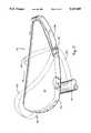
- FIG. 4is a side view of a bicycle seat cover shown placed over a bicycle seat.
- FIG. 5is a side view of the bicycle seat cover of FIG. 4 showing in stepwise fashion the drawstring being drawn over the bicycle seat.
- FIG. 1shows a top view of a padding device 10 comprising flowable materials 28 and 30 contained in pliable package 26.
- the flowable materialscomprise a combination of (1) a two-component base of wax and oil, and (2) discrete particles.
- the particlescan include, e.g. glassy, siliceous or ceramic micro-beads.
- Flowable materialsare described in greater detail in U.S. Pat. Nos. 3,237,319; 3,402,411; 3,635,849; 4,038,762; 4,083,127; 4,108,928; 4,144,658; 4,229,546; and 4,243,754 which are incorporated herein by reference in their entirety.
- the flowable materialwhen placed in a container such as an elastomeric envelope, is viscous, but flows and conforms under controlled or selective pressure loads. More specifically, the pressure compensating material is flowable or formable. It conforms or deforms to an irregular shape. It substantially retains that shape when relieved of deforming pressure It does not "sag" or slump significantly upon storage at ambient temperatures.
- the shape of the flowable materialmay be changed, for example, by the application of continuously applied pressure or shear stress that exceeds some desired minimum level. After the "yield point" of the flowable material is reached, it flows under shear stress. In this respect, the flowable material responds in a manner generally expected of a liquid. When the flowable material is confined, for example, within an envelope enclosure, during conditions of use the flowable material migrates in response to continually applied pressure, and is resistant to flow in response to instantaneously applied pressure
- the flowable materialdoes not constantly apply pressure, as it would if it were too resilient. It does not flow too quickly or too responsively, otherwise it would not resist flow in response to instantaneously applied pressure, while flowing in response to continuously applied pressure.
- the confined flowable materialundergoes flow and deformation away from the areas of highest pressure loads.
- the padding device 10is configured to be used on a bicycle seat. As will be appreciated by those skilled in the art, alternative configurations can be employed depending upon the specific application in which the padding device is to be used.
- the padding device 10comprises a narrow forward section 12 and a wider rear section 14.
- the wider rear section 14is separated into two side sections 16 and 18.
- the left rear section 16is partially separated from the right rear section 18 by a barrier 20.
- the barrier 20preferably is at least 1/4th the total length of the padding device 10, measured from front to rear.
- the barrier section 20includes an open area 22 and a sealed area 24 made up of material sealed in a manner to prevent the entry of flowable material 28 into the sealed area 24.
- the barrier 20provides numerous advantages. For example, it prevents the accumulation of flowable material under a portion of the human anatomy where such accumulation is undesirable.
- the barrier 20allows the padding device 10 to more easily conform to the shape of a bicycle seat, which is similar to that of a hyperbolic paraboloid.
- the barrier 20can controllably restrict the migration of flowable material 28 between side section 16 and side section 18. In other words, the flowable material must circumvent barrier 20 in order to migrate from side to side. Therefore, by the proper selection of the length of barrier 20, the speed at which the flowable material can migrate between side section 16 and side section 18 can be controlled.
- the barrier 20can comprise all open area 22, all sealed area 24, or a combination of the two, as shown in FIG. 1.
- the padding device 10comprises an enclosure envelope 26 surrounding flowable materials 28 and 30.
- the forward portion 12 of the padding device 10includes a multi-layer flowable material configuration.
- the first layer 28 of flowable materialis distributed substantially throughout the extent of the padding device 10 while the second layer 30 is located solely in the forward portion 12.
- the first layer 28is separated from the second layer 30 by a barrier 32.
- the flowable material 28 in the first layercan be the same or different than the flowable material 30 in the second layer, depending upon the particular application.
- the flowable material 28may be of a relatively higher viscosity, thereby providing a slower migration speed.
- the flowable material 30can be of a relatively lower viscosity, thereby providing a higher migration speed at certain areas of a bicycle seat. This is especially desirable toward the front narrow portion 12 of the bicycle seat padding device 10 due to the area of the human anatomy which contacts this area 12.
- Another advantageis that the multiple layer design helps prevent bottoming out of sharp protuberances placed on the multiple layer area.
- Another advantage with multi-layer configurationsis found when flowable material is injected into an envelope in order to custom fit an object, such as a ski boot.
- an envelopeis typically placed within an enclosure, such as a ski boot, and the object to be fit, e.g. a foot, is placed within the boot.
- Flowable materialis then injected into the envelope until a custom fit is obtained.
- the flowable materialhad to be less than a certain maximum viscosity in order to be easily injectable.
- a minimum amount of high viscosity flowable materialcan be placed inside the boot prior to the custom fitting operation.
- the multi-layer configurationscan be provided by providing a single envelope 26 having a barrier layer 32 separating the two different layers, as shown in FIGS. 1 and 2.
- two separate envelopescan be placed adjacent one another in order to provide the multi-layer configuration.
- the enclosure envelope 26can comprise any material capable of containing the flowable material. Preferably, the material is pliable.
- the enclosure envelope 26preferably comprises a first top sheet of elastomeric material 26a and a second bottom sheet of elastomeric material 26b between which flowable material 28 is placed. The two sheets are heat sealed at the periphery 26c in order to contain the flowable material 28.
- the barrier 32 which contains the second layer of flowable material 30can also comprise an elastomeric material which is heat sealed along the front of edges 26c and intermediate seal 34 (as shown in FIG. 1).
- the front portion 12 of the padding device 10includes areas, as shown by circles 36 and 38, where the bottom enclosure layer 26b is directly attached to the top enclosure layer 26a, with no flowable material therebetween.
- These connected areas 36 and 38provide a number of advantages.
- the areascan prevent excessive loft, that is they can prevent lower layer 26b from separating too far from upper layer 26a.
- the connecting portions 36 and 38can also act to controllably restrict the side-to-side flow or migration of flowable material.
- the connecting areas 36 and 38can substantially prevent relative lateral motion between top layer 26a and bottom layer 26b, i.e they can prevent "rolling".
- the sealed area 24can be extended in a forward direction to replace one or both of the sealed areas 36 and 38.
- a padding devicecomprising low compression set foam.
- the foamis a closed cell foam.
- Low compression set foammay comprise, e.g. cross-linked or uncross-linked polyethylene.
- the padding device 40can comprise, e.g. a padding device for use on a bicycle seat.
- the padding device 40can include a narrow front portion 42 and a wide rear portion 44.
- a slit 46can be provided so that the padding device 40 can better accommodate the shape of a bicycle seat, i.e. a shape similar to a hyperbolic paraboloid.
- the amount of low compression set a foam possessescan be quantified using the ASTM constant deflection compression set rating.
- the ASTM constant deflection compression setis measured as a percentage of original thickness, based on a deflection of 50%.
- the methodconsists of deflecting the foam specimen under specified conditions of time and temperature and noting the effect on the thickness on the specimen.
- the foamis deflected by two flat plates held parallel to each other by bolts or clamps.
- a piece of foamis compressed to 50% of its original thickness. The deflection is maintained for a period of 22 hours. The foam is then allowed to recover for 24 hours. The thickness of the foam is then measured again.
- the ASTM constant deflection compression set, C dexpressed as a percentage of the original thickness, is calculated as follows:
- padding devicesemploying low compression set foams having an ASTM rating of greater than 20%, and preferably greater than 35%, are provided.
- padding devicescomprising a combination of low compression set foam and flowable materials are provided. Because the characteristics of flowable material and low compression set foam complement one another, low compression set foams with ASTM ratings as low as 10% have been found to be useful when employed in combination with flowable material. It has also been found that the low compression set foam, when combined with the flowable material, helps to retain the shape of the padding device. Low compression set foam also alleviates problems associated with bottoming out of flowable material.
- a device and method for securing a bicycle seat cover to a bicycle seatis provided.
- the bicycle seat covercomprises a covering 52, preferably of cloth or fabric.
- a drawstring 54is enclosed within the lower edge of the covering 52.
- the enclosed portion of the drawstring 54is partially shown in phantom lines.
- the enclosurecan be accomplished, e.g. by folding the lower edge of the covering 52 around the drawstring 54 and sewing it to form a channel.
- the drawstringcan be threaded through a preexisting channel.
- a small loop 56is attached to the forward lower edge of the covering 52.
- the drawstring 54extends through the small loop 56.
- the small loop 56can comprise a single loop through which the entire drawstring 54 is drawn, or alternatively, it can comprise two separate loops through which each half of the drawstring can be drawn.
- the forward portion of the drawstringforms a loop shown as 55a in FIG. 4.
- the drawstring 54is a loop of flat elastic band.
- the cover 50is secured to the bicycle seat by: (1) drawing the loop 55a forwardly and upwardly as shown by 55b; (2) pulling the loop rearwardly over the top of the seat as shown in phantom lines 55c; (3) continuing rearwardly and then downwardly as shown in phantom lines 55d; and (4) releasing the drawstring 54 and allowing it to contact the bicycle seat support post 60 as shown in phantom lines 55e. In this manner the cover 50 is secured to the seat.
- the bicycle seat covering 52can be a piece of fabric, or alternatively it can be a combination of fabric and low compression set foam.
- a preferred fabricis LYCRA (TM).
Landscapes
- Engineering & Computer Science (AREA)
- Mechanical Engineering (AREA)
- Mattresses And Other Support Structures For Chairs And Beds (AREA)
Abstract
Description
C.sub.d =[(t.sub.o -t.sub.f)/t.sub.o ]×100
Claims (2)
Priority Applications (1)
| Application Number | Priority Date | Filing Date | Title |
|---|---|---|---|
| US07/657,489US5147685A (en) | 1988-10-14 | 1991-02-19 | Padding device |
Applications Claiming Priority (2)
| Application Number | Priority Date | Filing Date | Title |
|---|---|---|---|
| US07/257,955US4952439A (en) | 1988-10-14 | 1988-10-14 | Padding device |
| US07/657,489US5147685A (en) | 1988-10-14 | 1991-02-19 | Padding device |
Related Parent Applications (1)
| Application Number | Title | Priority Date | Filing Date |
|---|---|---|---|
| US07/573,365DivisionUS5058291A (en) | 1988-10-14 | 1990-08-27 | Padding device |
Publications (1)
| Publication Number | Publication Date |
|---|---|
| US5147685Atrue US5147685A (en) | 1992-09-15 |
Family
ID=26946310
Family Applications (1)
| Application Number | Title | Priority Date | Filing Date |
|---|---|---|---|
| US07/657,489Expired - Fee RelatedUS5147685A (en) | 1988-10-14 | 1991-02-19 | Padding device |
Country Status (1)
| Country | Link |
|---|---|
| US (1) | US5147685A (en) |
Cited By (45)
| Publication number | Priority date | Publication date | Assignee | Title |
|---|---|---|---|---|
| US5390384A (en)* | 1993-08-13 | 1995-02-21 | Jay Medical Ltd. | Self-adjusting seating system |
| US5464443A (en)* | 1993-05-03 | 1995-11-07 | Rik Medical, L.L.C. | Prosthetic device for amputees |
| US5549743A (en)* | 1993-06-22 | 1996-08-27 | Genesis Composites, L.C. | Composite microsphere and lubricant mixture |
| US5592706A (en)* | 1993-11-09 | 1997-01-14 | Teksource, Lc | Cushioning device formed from separate reshapable cells |
| US5711029A (en)* | 1996-06-21 | 1998-01-27 | Visco; Raymond D. | Protective apparatus for dispersing pressure applied at a joint |
| US5720518A (en)* | 1996-08-30 | 1998-02-24 | Harrison; Craig R. | Universal bike and exercycle seat cushion accessory |
| US5749111A (en)* | 1996-02-14 | 1998-05-12 | Teksource, Lc | Gelatinous cushions with buckling columns |
| US5803416A (en)* | 1995-04-06 | 1998-09-08 | Alden Laboratories, Inc. | Hand, wrist and/or lower arm support pad and assemblies |
| US5869164A (en) | 1995-11-08 | 1999-02-09 | Rik Medical Llc | Pressure-compensating compositions and pads made therefrom |
| US5881409A (en)* | 1993-06-22 | 1999-03-16 | Teksource, Ll | Puff-quilted bladders for containing flowable cushioning medium |
| US5904396A (en)* | 1997-10-22 | 1999-05-18 | Yates; Paul M. | Cushioned bicycle saddle |
| US5978970A (en)* | 1998-02-11 | 1999-11-09 | Bright; Patrick | Crotch cushion for a bicycle rider |
| US6007149A (en)* | 1998-09-04 | 1999-12-28 | Yates; Paul M. | Bicycle saddle with adjustable cushioning |
| US6135550A (en)* | 1999-04-01 | 2000-10-24 | Tucho; Tafesse | Bicycle seat |
| US20020161070A1 (en)* | 2001-02-01 | 2002-10-31 | Ellis Edward J. | Lightweight material for protective pads, cushions, supports or the like and method |
| US6583199B2 (en) | 2001-10-03 | 2003-06-24 | I-Tek, Inc. | Lightweight composite material for protective pads, cushions, supports or the like and method |
| US6591456B2 (en) | 2001-07-09 | 2003-07-15 | Bic Corporation | Cushioning device |
| US6598251B2 (en) | 2001-06-15 | 2003-07-29 | Hon Technology Inc. | Body support system |
| US20030153669A1 (en)* | 2001-12-20 | 2003-08-14 | Brother Theodore B. | Lightweight composite material for protective pads, cushions, supports or the like and method |
| US20030164629A1 (en)* | 2000-08-04 | 2003-09-04 | Riccardo Bigolin | Saddle made of composite material, in patricular for a bicycle, and method for the manufacture thereof |
| US20040136769A1 (en)* | 2001-02-27 | 2004-07-15 | Ferrara Daniel A. | Cushioning element |
| US6827397B1 (en) | 2003-08-10 | 2004-12-07 | Burch Driver | Adjustable bicycle seat |
| US6860552B1 (en)* | 2000-04-28 | 2005-03-01 | Giuseppe Bigolin | Bicycle saddle |
| US20050046245A1 (en)* | 2003-08-27 | 2005-03-03 | Tsai-Yun Yu | Bicycle saddle |
| US20050227584A1 (en)* | 2004-04-06 | 2005-10-13 | Barbara Stachowski | Padded clothing articles and method for making the same |
| US20050278836A1 (en)* | 2004-06-22 | 2005-12-22 | Nelson Thomas M | Fluid filled body padding for fall protection |
| US20070108808A1 (en)* | 2005-11-17 | 2007-05-17 | Louis Chuang | Bicycle saddle |
| US20070152481A1 (en)* | 2004-10-01 | 2007-07-05 | Pandozy Raffaele M | Anatomically supportive bicycle seat |
| EP1815758A1 (en)* | 2006-02-01 | 2007-08-08 | Campagnolo Sportswear S.r.l. | Protection for cycling pants |
| US20080007099A1 (en)* | 2006-01-27 | 2008-01-10 | Louis Chuang | Bicycle Saddle |
| US20080178360A1 (en)* | 2007-01-31 | 2008-07-31 | Nike, Inc. | Leg guard |
| US20080178361A1 (en)* | 2007-01-31 | 2008-07-31 | Nike, Inc. | Protective knee covering |
| US20080197680A1 (en)* | 2007-02-16 | 2008-08-21 | Louis Chuang | Bicycle Saddle |
| US20090261632A1 (en)* | 2005-11-17 | 2009-10-22 | Louis Chuang | Bicycle Saddle |
| US20100183847A1 (en)* | 2007-08-23 | 2010-07-22 | Pearce Tony M | Alternating pattern gel cushioning elements and related methods |
| KR101158668B1 (en) | 2011-05-23 | 2012-07-03 | 김철수 | Bicycle seat for protecting scrotum and perineal region capable of preventing hip from be deviated |
| US8424137B1 (en) | 2007-11-27 | 2013-04-23 | Edizone, Llc | Ribbed gel |
| US8434748B1 (en) | 2007-10-03 | 2013-05-07 | Edizone, Llc | Cushions comprising gel springs |
| US20130207423A1 (en)* | 2012-02-14 | 2013-08-15 | Janis Linda Russell | Bicycle seat cover with integrated storage device |
| US8566233B2 (en) | 2010-07-29 | 2013-10-22 | Intel Corporation | Device, system, and method for location-based payment authorization |
| US8628067B2 (en) | 2008-10-03 | 2014-01-14 | Edizone, Llc | Cushions comprising core structures and related methods |
| US8932692B2 (en) | 2008-10-03 | 2015-01-13 | Edizone, Llc | Cushions comprising deformable members and related methods |
| USD778079S1 (en) | 2015-09-11 | 2017-02-07 | David R. Porter | Bicycle saddle |
| US9855174B1 (en)* | 2012-06-29 | 2018-01-02 | Ki Mobility | Wheelchair cushion with adjustable/multi-stiffness fluid |
| US10435097B2 (en)* | 2014-11-26 | 2019-10-08 | Jarik Medical, LLC | Bicycle seat for protecting ischial tuberosities |
Citations (21)
| Publication number | Priority date | Publication date | Assignee | Title |
|---|---|---|---|---|
| US3237319A (en)* | 1964-06-22 | 1966-03-01 | Hanson Alden Wade | Ski boots having a thixotropic material encircling the ankle portion thereof |
| US3402411A (en)* | 1966-01-12 | 1968-09-24 | Hanson Alden Wade | Process for making boots, sports equipment and hats |
| US3635849A (en)* | 1969-09-08 | 1972-01-18 | University Patents Inc | Polyisobutylene paraffin wax and oil blends |
| US3807793A (en)* | 1972-02-09 | 1974-04-30 | D Jacobs | Bicycle seat |
| US3844611A (en)* | 1972-08-03 | 1974-10-29 | Troxel Mfg Co | Cycle saddle |
| US3997214A (en)* | 1972-02-09 | 1976-12-14 | The Jacobs Corporation | Bicycle seat |
| US4038762A (en)* | 1976-03-02 | 1977-08-02 | Hanson Industries Inc. | Viscous, flowable, pressure-compensating fitting materials and their use, including their use in boots |
| US4083127A (en)* | 1977-03-17 | 1978-04-11 | Hanson Industries Incorporated | Adjustable, pressure-compensating, custom fitting pads having predetermined amount of fitting material and their use in boots |
| US4108928A (en)* | 1976-03-02 | 1978-08-22 | Hanson Industries Inc. | Method of producing a viscous flowable pressure-compensating fitting composition from hollow thermoplastic microblends with the use of high frequency heating and dispensing the composition into a sealable, flexible, protective enclosure means |
| US4144658A (en)* | 1976-09-16 | 1979-03-20 | Hanson Industries Inc. | Viscous, flowable, pressure-compensating fitting materials and their use, including their use in boots |
| US4229546A (en)* | 1978-07-27 | 1980-10-21 | Hanson Industries Incorporated | Viscous, flowable, pressure-compensating fitting compositions having therein both glass and resinous microbeads |
| US4243754A (en)* | 1978-09-05 | 1981-01-06 | Hanson Industries Incorporated | Viscous, flowable, pressure-compensating fitting compositions |
| US4370769A (en)* | 1980-09-19 | 1983-02-01 | Herzig Ralph B | Cushion utilizing air and liquid |
| US4429915A (en)* | 1981-03-13 | 1984-02-07 | Flager Calvin D | Bicycle seat |
| US4445240A (en)* | 1978-08-07 | 1984-05-01 | Ideal Comfort, Inc. | Liquid filled compartmented cushion |
| US4504089A (en)* | 1982-01-25 | 1985-03-12 | Nathaniel Calvert | Liquid-cushioned bicycle seat |
| US4520248A (en)* | 1980-08-15 | 1985-05-28 | Rogers Corporation | Keyboard assembly |
| US4724560A (en)* | 1987-02-10 | 1988-02-16 | Christie Larry L | Pillow utilizing air and water |
| US4733907A (en)* | 1986-06-13 | 1988-03-29 | Fellenbaum Ernest S | Bicycle cushion seat cover with aerodynamic shaped bag |
| US4752626A (en)* | 1987-08-27 | 1988-06-21 | General Motors Corporation | Method of making low compression set urethane foams |
| US4803744A (en)* | 1987-05-19 | 1989-02-14 | Hill-Rom Company, Inc. | Inflatable bed |
- 1991
- 1991-02-19USUS07/657,489patent/US5147685A/ennot_activeExpired - Fee Related
Patent Citations (21)
| Publication number | Priority date | Publication date | Assignee | Title |
|---|---|---|---|---|
| US3237319A (en)* | 1964-06-22 | 1966-03-01 | Hanson Alden Wade | Ski boots having a thixotropic material encircling the ankle portion thereof |
| US3402411A (en)* | 1966-01-12 | 1968-09-24 | Hanson Alden Wade | Process for making boots, sports equipment and hats |
| US3635849A (en)* | 1969-09-08 | 1972-01-18 | University Patents Inc | Polyisobutylene paraffin wax and oil blends |
| US3807793A (en)* | 1972-02-09 | 1974-04-30 | D Jacobs | Bicycle seat |
| US3997214A (en)* | 1972-02-09 | 1976-12-14 | The Jacobs Corporation | Bicycle seat |
| US3844611A (en)* | 1972-08-03 | 1974-10-29 | Troxel Mfg Co | Cycle saddle |
| US4038762A (en)* | 1976-03-02 | 1977-08-02 | Hanson Industries Inc. | Viscous, flowable, pressure-compensating fitting materials and their use, including their use in boots |
| US4108928A (en)* | 1976-03-02 | 1978-08-22 | Hanson Industries Inc. | Method of producing a viscous flowable pressure-compensating fitting composition from hollow thermoplastic microblends with the use of high frequency heating and dispensing the composition into a sealable, flexible, protective enclosure means |
| US4144658A (en)* | 1976-09-16 | 1979-03-20 | Hanson Industries Inc. | Viscous, flowable, pressure-compensating fitting materials and their use, including their use in boots |
| US4083127A (en)* | 1977-03-17 | 1978-04-11 | Hanson Industries Incorporated | Adjustable, pressure-compensating, custom fitting pads having predetermined amount of fitting material and their use in boots |
| US4229546A (en)* | 1978-07-27 | 1980-10-21 | Hanson Industries Incorporated | Viscous, flowable, pressure-compensating fitting compositions having therein both glass and resinous microbeads |
| US4445240A (en)* | 1978-08-07 | 1984-05-01 | Ideal Comfort, Inc. | Liquid filled compartmented cushion |
| US4243754A (en)* | 1978-09-05 | 1981-01-06 | Hanson Industries Incorporated | Viscous, flowable, pressure-compensating fitting compositions |
| US4520248A (en)* | 1980-08-15 | 1985-05-28 | Rogers Corporation | Keyboard assembly |
| US4370769A (en)* | 1980-09-19 | 1983-02-01 | Herzig Ralph B | Cushion utilizing air and liquid |
| US4429915A (en)* | 1981-03-13 | 1984-02-07 | Flager Calvin D | Bicycle seat |
| US4504089A (en)* | 1982-01-25 | 1985-03-12 | Nathaniel Calvert | Liquid-cushioned bicycle seat |
| US4733907A (en)* | 1986-06-13 | 1988-03-29 | Fellenbaum Ernest S | Bicycle cushion seat cover with aerodynamic shaped bag |
| US4724560A (en)* | 1987-02-10 | 1988-02-16 | Christie Larry L | Pillow utilizing air and water |
| US4803744A (en)* | 1987-05-19 | 1989-02-14 | Hill-Rom Company, Inc. | Inflatable bed |
| US4752626A (en)* | 1987-08-27 | 1988-06-21 | General Motors Corporation | Method of making low compression set urethane foams |
Non-Patent Citations (2)
| Title |
|---|
| Dec. 1986 Pearl Izumi Bicycle Clothing for Racing and Touring Catalog, Shimizu Jacobs, Inc. (p. 13).* |
| Dec. 1986 Pearl Izumi Bicycle Clothing for Racing and Touring Catalog, Shimizu-Jacobs, Inc. (p. 13). |
Cited By (67)
| Publication number | Priority date | Publication date | Assignee | Title |
|---|---|---|---|---|
| US5464443A (en)* | 1993-05-03 | 1995-11-07 | Rik Medical, L.L.C. | Prosthetic device for amputees |
| US6020055A (en)* | 1993-06-22 | 2000-02-01 | Teksource, Lc | Cushioning media including lubricated spherical objects |
| US5549743A (en)* | 1993-06-22 | 1996-08-27 | Genesis Composites, L.C. | Composite microsphere and lubricant mixture |
| US6197099B1 (en) | 1993-06-22 | 2001-03-06 | Tony M. Pearce | Flowable cushioning media including lubricated spherical objects |
| US5881409A (en)* | 1993-06-22 | 1999-03-16 | Teksource, Ll | Puff-quilted bladders for containing flowable cushioning medium |
| US5390384A (en)* | 1993-08-13 | 1995-02-21 | Jay Medical Ltd. | Self-adjusting seating system |
| US5592706A (en)* | 1993-11-09 | 1997-01-14 | Teksource, Lc | Cushioning device formed from separate reshapable cells |
| US5829081A (en)* | 1993-11-09 | 1998-11-03 | Teksource, Lc | Cushioning device formed from separate reshapable cells |
| US5803416A (en)* | 1995-04-06 | 1998-09-08 | Alden Laboratories, Inc. | Hand, wrist and/or lower arm support pad and assemblies |
| US5869164A (en) | 1995-11-08 | 1999-02-09 | Rik Medical Llc | Pressure-compensating compositions and pads made therefrom |
| US5749111A (en)* | 1996-02-14 | 1998-05-12 | Teksource, Lc | Gelatinous cushions with buckling columns |
| US6026527A (en)* | 1996-02-14 | 2000-02-22 | Edizone, Lc | Gelatinous cushions with buckling columns |
| US5711029A (en)* | 1996-06-21 | 1998-01-27 | Visco; Raymond D. | Protective apparatus for dispersing pressure applied at a joint |
| US5720518A (en)* | 1996-08-30 | 1998-02-24 | Harrison; Craig R. | Universal bike and exercycle seat cushion accessory |
| US5904396A (en)* | 1997-10-22 | 1999-05-18 | Yates; Paul M. | Cushioned bicycle saddle |
| US5978970A (en)* | 1998-02-11 | 1999-11-09 | Bright; Patrick | Crotch cushion for a bicycle rider |
| US6007149A (en)* | 1998-09-04 | 1999-12-28 | Yates; Paul M. | Bicycle saddle with adjustable cushioning |
| US6135550A (en)* | 1999-04-01 | 2000-10-24 | Tucho; Tafesse | Bicycle seat |
| US6860552B1 (en)* | 2000-04-28 | 2005-03-01 | Giuseppe Bigolin | Bicycle saddle |
| US20030164629A1 (en)* | 2000-08-04 | 2003-09-04 | Riccardo Bigolin | Saddle made of composite material, in patricular for a bicycle, and method for the manufacture thereof |
| US7044540B2 (en)* | 2000-08-04 | 2006-05-16 | Selle Royal, S.P.A. | Saddle made of composite material, in particular for a bicycle |
| US20020161070A1 (en)* | 2001-02-01 | 2002-10-31 | Ellis Edward J. | Lightweight material for protective pads, cushions, supports or the like and method |
| US6835763B2 (en) | 2001-02-01 | 2004-12-28 | I-Tek, Inc. | Lightweight material for protective pads, cushions, supports or the like and method |
| US20040136769A1 (en)* | 2001-02-27 | 2004-07-15 | Ferrara Daniel A. | Cushioning element |
| US7004655B2 (en) | 2001-02-27 | 2006-02-28 | Ferrara Daniel A | Cushioning element |
| US6598251B2 (en) | 2001-06-15 | 2003-07-29 | Hon Technology Inc. | Body support system |
| US6687933B2 (en) | 2001-06-15 | 2004-02-10 | Hon Technology, Inc. | Body support system with energy dissipation means |
| US6591456B2 (en) | 2001-07-09 | 2003-07-15 | Bic Corporation | Cushioning device |
| US6583199B2 (en) | 2001-10-03 | 2003-06-24 | I-Tek, Inc. | Lightweight composite material for protective pads, cushions, supports or the like and method |
| US20030153669A1 (en)* | 2001-12-20 | 2003-08-14 | Brother Theodore B. | Lightweight composite material for protective pads, cushions, supports or the like and method |
| US6756426B2 (en) | 2001-12-20 | 2004-06-29 | I-Tek, Inc. | Lightweight composite material for protective pads, cushions, supports or the like and method |
| US6827397B1 (en) | 2003-08-10 | 2004-12-07 | Burch Driver | Adjustable bicycle seat |
| US20050046245A1 (en)* | 2003-08-27 | 2005-03-03 | Tsai-Yun Yu | Bicycle saddle |
| US6886887B2 (en)* | 2003-08-27 | 2005-05-03 | Tsai-Yun Yu | Bicycle saddle |
| US20050227584A1 (en)* | 2004-04-06 | 2005-10-13 | Barbara Stachowski | Padded clothing articles and method for making the same |
| US20050278836A1 (en)* | 2004-06-22 | 2005-12-22 | Nelson Thomas M | Fluid filled body padding for fall protection |
| US6986170B2 (en) | 2004-06-22 | 2006-01-17 | Nelson Thomas M | Fluid filled body padding for fall protection |
| US20070152481A1 (en)* | 2004-10-01 | 2007-07-05 | Pandozy Raffaele M | Anatomically supportive bicycle seat |
| US7478871B2 (en) | 2004-10-01 | 2009-01-20 | Raffaele Martini Pandozy | Anatomically supportive bicycle seat |
| US20090261632A1 (en)* | 2005-11-17 | 2009-10-22 | Louis Chuang | Bicycle Saddle |
| US20070108808A1 (en)* | 2005-11-17 | 2007-05-17 | Louis Chuang | Bicycle saddle |
| US8297696B2 (en) | 2005-11-17 | 2012-10-30 | Louis Chuang | Bicycle saddle |
| US8047604B2 (en) | 2005-11-17 | 2011-11-01 | Louis Chuang | Bicycle saddle |
| US20080007099A1 (en)* | 2006-01-27 | 2008-01-10 | Louis Chuang | Bicycle Saddle |
| US7699392B2 (en) | 2006-01-27 | 2010-04-20 | Louis Chuang | Bicycle saddle |
| EP1815758A1 (en)* | 2006-02-01 | 2007-08-08 | Campagnolo Sportswear S.r.l. | Protection for cycling pants |
| US20070186328A1 (en)* | 2006-02-01 | 2007-08-16 | Campagnolo Sportswear S.R.L. | Protection for cycling pants |
| US7832017B2 (en) | 2007-01-31 | 2010-11-16 | Nike, Inc. | Leg guard |
| US8256021B2 (en) | 2007-01-31 | 2012-09-04 | Nike, Inc. | Leg guard |
| US7512996B2 (en)* | 2007-01-31 | 2009-04-07 | Nike, Inc. | Protective knee covering |
| US20080178360A1 (en)* | 2007-01-31 | 2008-07-31 | Nike, Inc. | Leg guard |
| US20080178361A1 (en)* | 2007-01-31 | 2008-07-31 | Nike, Inc. | Protective knee covering |
| US20110016597A1 (en)* | 2007-01-31 | 2011-01-27 | Nike, Inc. | Leg Guard |
| US20080197680A1 (en)* | 2007-02-16 | 2008-08-21 | Louis Chuang | Bicycle Saddle |
| US7661757B2 (en)* | 2007-02-16 | 2010-02-16 | Louis Chuang | Bicycle saddle |
| US20100183847A1 (en)* | 2007-08-23 | 2010-07-22 | Pearce Tony M | Alternating pattern gel cushioning elements and related methods |
| US8075981B2 (en) | 2007-08-23 | 2011-12-13 | Edizone, Llc | Alternating pattern gel cushioning elements and related methods |
| US8434748B1 (en) | 2007-10-03 | 2013-05-07 | Edizone, Llc | Cushions comprising gel springs |
| US8424137B1 (en) | 2007-11-27 | 2013-04-23 | Edizone, Llc | Ribbed gel |
| US8628067B2 (en) | 2008-10-03 | 2014-01-14 | Edizone, Llc | Cushions comprising core structures and related methods |
| US8932692B2 (en) | 2008-10-03 | 2015-01-13 | Edizone, Llc | Cushions comprising deformable members and related methods |
| US8566233B2 (en) | 2010-07-29 | 2013-10-22 | Intel Corporation | Device, system, and method for location-based payment authorization |
| KR101158668B1 (en) | 2011-05-23 | 2012-07-03 | 김철수 | Bicycle seat for protecting scrotum and perineal region capable of preventing hip from be deviated |
| US20130207423A1 (en)* | 2012-02-14 | 2013-08-15 | Janis Linda Russell | Bicycle seat cover with integrated storage device |
| US9855174B1 (en)* | 2012-06-29 | 2018-01-02 | Ki Mobility | Wheelchair cushion with adjustable/multi-stiffness fluid |
| US10435097B2 (en)* | 2014-11-26 | 2019-10-08 | Jarik Medical, LLC | Bicycle seat for protecting ischial tuberosities |
| USD778079S1 (en) | 2015-09-11 | 2017-02-07 | David R. Porter | Bicycle saddle |
Similar Documents
| Publication | Publication Date | Title |
|---|---|---|
| US5147685A (en) | Padding device | |
| US4952439A (en) | Padding device | |
| US5058291A (en) | Padding device | |
| US5189747A (en) | Seat cushion | |
| US5720518A (en) | Universal bike and exercycle seat cushion accessory | |
| CA2135664C (en) | Seat cushion assembly | |
| US5330249A (en) | Cushion for absorbing shock, damping vibration and distributing pressure | |
| US4522447A (en) | Foam seat and back cushions | |
| KR100322248B1 (en) | Spine Support System for Chair | |
| US9021637B1 (en) | Wheelchair cushion with adjustable/multi-stiffness fluid | |
| US5195199A (en) | Fluid cushion | |
| US4189182A (en) | Step tapered back rest cushion | |
| US20170079440A1 (en) | Molded Seat | |
| US20030042770A1 (en) | Base of bicycle saddle | |
| WO1985000512A1 (en) | A pressure exerting device | |
| JP2005523138A (en) | Cushioning device using beads | |
| US20140239678A1 (en) | Molded seat | |
| CN107207061B (en) | Bicycle seat | |
| US4458943A (en) | Spring seat | |
| EP2897497B1 (en) | Molded seat | |
| US6390548B1 (en) | Bicycle seat with inflatable interior | |
| US4847931A (en) | Water pillow | |
| US11857079B2 (en) | Internal support system for cushions, mattresses and the like | |
| US9756995B2 (en) | Reduced strain toilet seat | |
| GB2117235A (en) | A back support cushion |
Legal Events
| Date | Code | Title | Description |
|---|---|---|---|
| AS | Assignment | Owner name:ALDEN LABORATORIES, INC., 5455 SPINE RD., STE. A, Free format text:ASSIGNMENT OF ASSIGNORS INTEREST.;ASSIGNOR:HANSON, CHRIS A.;REEL/FRAME:005607/0778 Effective date:19910213 | |
| AS | Assignment | Owner name:BANK ONE, BOULDER, N.A., COLORADO Free format text:SECURITY INTEREST;ASSIGNOR:ALDEN LABORATORIES, INC.;REEL/FRAME:006817/0004 Effective date:19930412 | |
| FPAY | Fee payment | Year of fee payment:4 | |
| AS | Assignment | Owner name:BANK ONE, COLORADO, N.A., COLORADO Free format text:SECURITY AGREEMENT;ASSIGNOR:ALDEN LABORATORIES, INC.;REEL/FRAME:008470/0201 Effective date:19961126 | |
| AS | Assignment | Owner name:ALDEN LABORATORIES, INC., COLORADO Free format text:SECURITY INTEREST RELEASE;ASSIGNOR:BANK ONE, COLORADO, N.A., FORMERLY KNOWN AS BANK ONE, BOULDER;REEL/FRAME:008345/0307 Effective date:19961120 | |
| AS | Assignment | Owner name:SUNRISE MEDICAL INC., CALIFORNIA Free format text:ABSTRACT OF SETTLEMENT AGREEMENT AND RELEASE;ASSIGNORS:ALDEN LABORATORIES, INC.;FLOFIT MEDICAL, LLC;PRESSURE RELIEF TECHNOLOGIES, INC.;AND OTHERS;REEL/FRAME:008677/0016 Effective date:19961119 Owner name:JAY MEDICAL LTD., COLORADO Free format text:ABSTRACT OF SETTLEMENT AGREEMENT AND RELEASE;ASSIGNORS:ALDEN LABORATORIES, INC.;FLOFIT MEDICAL, LLC;PRESSURE RELIEF TECHNOLOGIES, INC.;AND OTHERS;REEL/FRAME:008677/0016 Effective date:19961119 Owner name:JAY, ERIC C., COLORADO Free format text:ABSTRACT OF SETTLEMENT AGREEMENT AND RELEASE;ASSIGNORS:ALDEN LABORATORIES, INC.;FLOFIT MEDICAL, LLC;PRESSURE RELIEF TECHNOLOGIES, INC.;AND OTHERS;REEL/FRAME:008677/0016 Effective date:19961119 Owner name:FLOWFIT MEDICAL, LLC, COLORADO Free format text:ABSTRACT OF SETTLEMENT AGREEMENT AND RELEASE;ASSIGNORS:ALDEN LABORATORIES, INC.;FLOFIT MEDICAL, LLC;PRESSURE RELIEF TECHNOLOGIES, INC.;AND OTHERS;REEL/FRAME:008677/0016 Effective date:19961119 Owner name:HANSON, ALDEN B., COLORADO Free format text:ABSTRACT OF SETTLEMENT AGREEMENT AND RELEASE;ASSIGNORS:ALDEN LABORATORIES, INC.;FLOFIT MEDICAL, LLC;PRESSURE RELIEF TECHNOLOGIES, INC.;AND OTHERS;REEL/FRAME:008677/0016 Effective date:19961119 Owner name:HANSON, CHRIS A., COLORADO Free format text:ABSTRACT OF SETTLEMENT AGREEMENT AND RELEASE;ASSIGNORS:ALDEN LABORATORIES, INC.;FLOFIT MEDICAL, LLC;PRESSURE RELIEF TECHNOLOGIES, INC.;AND OTHERS;REEL/FRAME:008677/0016 Effective date:19961119 Owner name:ALDEN LABORATORIES, INC., COLORADO Free format text:ABSTRACT OF SETTLEMENT AGREEMENT AND RELEASE;ASSIGNORS:ALDEN LABORATORIES, INC.;FLOFIT MEDICAL, LLC;PRESSURE RELIEF TECHNOLOGIES, INC.;AND OTHERS;REEL/FRAME:008677/0016 Effective date:19961119 Owner name:RIK MEDICAL, LLC, COLORADO Free format text:ABSTRACT OF SETTLEMENT AGREEMENT AND RELEASE;ASSIGNORS:ALDEN LABORATORIES, INC.;FLOFIT MEDICAL, LLC;PRESSURE RELIEF TECHNOLOGIES, INC.;AND OTHERS;REEL/FRAME:008677/0016 Effective date:19961119 Owner name:QUICKIE DESIGNS INC., CALIFORNIA Free format text:ABSTRACT OF SETTLEMENT AGREEMENT AND RELEASE;ASSIGNORS:ALDEN LABORATORIES, INC.;FLOFIT MEDICAL, LLC;PRESSURE RELIEF TECHNOLOGIES, INC.;AND OTHERS;REEL/FRAME:008677/0016 Effective date:19961119 Owner name:PRESSURE RELIEF TECHNOLOGIES, INC., COLORADO Free format text:ABSTRACT OF SETTLEMENT AGREEMENT AND RELEASE;ASSIGNORS:ALDEN LABORATORIES, INC.;FLOFIT MEDICAL, LLC;PRESSURE RELIEF TECHNOLOGIES, INC.;AND OTHERS;REEL/FRAME:008677/0016 Effective date:19961119 | |
| REMI | Maintenance fee reminder mailed | ||
| LAPS | Lapse for failure to pay maintenance fees | ||
| FP | Lapsed due to failure to pay maintenance fee | Effective date:20000915 | |
| STCH | Information on status: patent discontinuation | Free format text:PATENT EXPIRED DUE TO NONPAYMENT OF MAINTENANCE FEES UNDER 37 CFR 1.362 |