US5147186A - Blood pump drive system - Google Patents
Blood pump drive systemDownload PDFInfo
- Publication number
- US5147186A US5147186AUS07/638,366US63836691AUS5147186AUS 5147186 AUS5147186 AUS 5147186AUS 63836691 AUS63836691 AUS 63836691AUS 5147186 AUS5147186 AUS 5147186A
- Authority
- US
- United States
- Prior art keywords
- pump
- console
- coupler
- rotator
- motor
- Prior art date
- Legal status (The legal status is an assumption and is not a legal conclusion. Google has not performed a legal analysis and makes no representation as to the accuracy of the status listed.)
- Expired - Lifetime
Links
- 239000008280bloodSubstances0.000titleclaimsdescription10
- 210000004369bloodAnatomy0.000titleclaimsdescription10
- 238000012546transferMethods0.000claimsabstractdescription9
- 230000008878couplingEffects0.000claimsabstractdescription7
- 238000010168coupling processMethods0.000claimsabstractdescription7
- 238000005859coupling reactionMethods0.000claimsabstractdescription7
- 238000005086pumpingMethods0.000claimsdescription2
- 230000002093peripheral effectEffects0.000claims1
- 230000007246mechanismEffects0.000abstractdescription3
- 230000010412perfusionEffects0.000abstractdescription3
- 230000005540biological transmissionEffects0.000description4
- 230000004888barrier functionEffects0.000description2
- 230000017531blood circulationEffects0.000description2
- 238000006073displacement reactionMethods0.000description2
- 239000012530fluidSubstances0.000description2
- 230000005381magnetic domainEffects0.000description2
- 230000002265preventionEffects0.000description2
- 238000001356surgical procedureMethods0.000description2
- 230000009471actionEffects0.000description1
- 238000013459approachMethods0.000description1
- 230000000712assemblyEffects0.000description1
- 238000000429assemblyMethods0.000description1
- 239000000560biocompatible materialSubstances0.000description1
- 230000008081blood perfusionEffects0.000description1
- 238000010276constructionMethods0.000description1
- 230000007547defectEffects0.000description1
- 238000013461designMethods0.000description1
- 230000001050lubricating effectEffects0.000description1
- 230000014759maintenance of locationEffects0.000description1
- 238000004519manufacturing processMethods0.000description1
- 239000000463materialSubstances0.000description1
- 238000000034methodMethods0.000description1
- 230000004048modificationEffects0.000description1
- 238000012986modificationMethods0.000description1
- 238000012544monitoring processMethods0.000description1
- 238000012354overpressurizationMethods0.000description1
- 230000002572peristaltic effectEffects0.000description1
- 230000004044responseEffects0.000description1
- 230000000717retained effectEffects0.000description1
- 210000003813thumbAnatomy0.000description1
- 230000009466transformationEffects0.000description1
- 230000002792vascularEffects0.000description1
Images


Classifications
- H—ELECTRICITY
- H02—GENERATION; CONVERSION OR DISTRIBUTION OF ELECTRIC POWER
- H02K—DYNAMO-ELECTRIC MACHINES
- H02K49/00—Dynamo-electric clutches; Dynamo-electric brakes
- H02K49/10—Dynamo-electric clutches; Dynamo-electric brakes of the permanent-magnet type
- H02K49/104—Magnetic couplings consisting of only two coaxial rotary elements, i.e. the driving element and the driven element
- H02K49/108—Magnetic couplings consisting of only two coaxial rotary elements, i.e. the driving element and the driven element with an axial air gap
- A—HUMAN NECESSITIES
- A61—MEDICAL OR VETERINARY SCIENCE; HYGIENE
- A61M—DEVICES FOR INTRODUCING MEDIA INTO, OR ONTO, THE BODY; DEVICES FOR TRANSDUCING BODY MEDIA OR FOR TAKING MEDIA FROM THE BODY; DEVICES FOR PRODUCING OR ENDING SLEEP OR STUPOR
- A61M60/00—Blood pumps; Devices for mechanical circulatory actuation; Balloon pumps for circulatory assistance
- A61M60/10—Location thereof with respect to the patient's body
- A61M60/104—Extracorporeal pumps, i.e. the blood being pumped outside the patient's body
- A61M60/109—Extracorporeal pumps, i.e. the blood being pumped outside the patient's body incorporated within extracorporeal blood circuits or systems
- A61M60/113—Extracorporeal pumps, i.e. the blood being pumped outside the patient's body incorporated within extracorporeal blood circuits or systems in other functional devices, e.g. dialysers or heart-lung machines
- A—HUMAN NECESSITIES
- A61—MEDICAL OR VETERINARY SCIENCE; HYGIENE
- A61M—DEVICES FOR INTRODUCING MEDIA INTO, OR ONTO, THE BODY; DEVICES FOR TRANSDUCING BODY MEDIA OR FOR TAKING MEDIA FROM THE BODY; DEVICES FOR PRODUCING OR ENDING SLEEP OR STUPOR
- A61M60/00—Blood pumps; Devices for mechanical circulatory actuation; Balloon pumps for circulatory assistance
- A61M60/20—Type thereof
- A61M60/205—Non-positive displacement blood pumps
- A61M60/216—Non-positive displacement blood pumps including a rotating member acting on the blood, e.g. impeller
- A—HUMAN NECESSITIES
- A61—MEDICAL OR VETERINARY SCIENCE; HYGIENE
- A61M—DEVICES FOR INTRODUCING MEDIA INTO, OR ONTO, THE BODY; DEVICES FOR TRANSDUCING BODY MEDIA OR FOR TAKING MEDIA FROM THE BODY; DEVICES FOR PRODUCING OR ENDING SLEEP OR STUPOR
- A61M60/00—Blood pumps; Devices for mechanical circulatory actuation; Balloon pumps for circulatory assistance
- A61M60/30—Medical purposes thereof other than the enhancement of the cardiac output
- A61M60/31—Medical purposes thereof other than the enhancement of the cardiac output for enhancement of in vivo organ perfusion, e.g. retroperfusion
- A—HUMAN NECESSITIES
- A61—MEDICAL OR VETERINARY SCIENCE; HYGIENE
- A61M—DEVICES FOR INTRODUCING MEDIA INTO, OR ONTO, THE BODY; DEVICES FOR TRANSDUCING BODY MEDIA OR FOR TAKING MEDIA FROM THE BODY; DEVICES FOR PRODUCING OR ENDING SLEEP OR STUPOR
- A61M60/00—Blood pumps; Devices for mechanical circulatory actuation; Balloon pumps for circulatory assistance
- A61M60/40—Details relating to driving
- A61M60/403—Details relating to driving for non-positive displacement blood pumps
- A61M60/419—Details relating to driving for non-positive displacement blood pumps the force acting on the blood contacting member being permanent magnetic, e.g. from a rotating magnetic coupling between driving and driven magnets
- A—HUMAN NECESSITIES
- A61—MEDICAL OR VETERINARY SCIENCE; HYGIENE
- A61M—DEVICES FOR INTRODUCING MEDIA INTO, OR ONTO, THE BODY; DEVICES FOR TRANSDUCING BODY MEDIA OR FOR TAKING MEDIA FROM THE BODY; DEVICES FOR PRODUCING OR ENDING SLEEP OR STUPOR
- A61M60/00—Blood pumps; Devices for mechanical circulatory actuation; Balloon pumps for circulatory assistance
- A61M60/80—Constructional details other than related to driving
- A61M60/802—Constructional details other than related to driving of non-positive displacement blood pumps
- A61M60/818—Bearings
- A61M60/824—Hydrodynamic or fluid film bearings
- F—MECHANICAL ENGINEERING; LIGHTING; HEATING; WEAPONS; BLASTING
- F04—POSITIVE - DISPLACEMENT MACHINES FOR LIQUIDS; PUMPS FOR LIQUIDS OR ELASTIC FLUIDS
- F04D—NON-POSITIVE-DISPLACEMENT PUMPS
- F04D13/00—Pumping installations or systems
- F04D13/02—Units comprising pumps and their driving means
- F04D13/021—Units comprising pumps and their driving means containing a coupling
- F04D13/024—Units comprising pumps and their driving means containing a coupling a magnetic coupling
- F04D13/027—Details of the magnetic circuit
- F—MECHANICAL ENGINEERING; LIGHTING; HEATING; WEAPONS; BLASTING
- F04—POSITIVE - DISPLACEMENT MACHINES FOR LIQUIDS; PUMPS FOR LIQUIDS OR ELASTIC FLUIDS
- F04D—NON-POSITIVE-DISPLACEMENT PUMPS
- F04D13/00—Pumping installations or systems
- F04D13/02—Units comprising pumps and their driving means
- F04D13/06—Units comprising pumps and their driving means the pump being electrically driven
- F—MECHANICAL ENGINEERING; LIGHTING; HEATING; WEAPONS; BLASTING
- F04—POSITIVE - DISPLACEMENT MACHINES FOR LIQUIDS; PUMPS FOR LIQUIDS OR ELASTIC FLUIDS
- F04D—NON-POSITIVE-DISPLACEMENT PUMPS
- F04D29/00—Details, component parts, or accessories
- F04D29/60—Mounting; Assembling; Disassembling
- F04D29/62—Mounting; Assembling; Disassembling of radial or helico-centrifugal pumps
- F04D29/628—Mounting; Assembling; Disassembling of radial or helico-centrifugal pumps especially adapted for liquid pumps
- F—MECHANICAL ENGINEERING; LIGHTING; HEATING; WEAPONS; BLASTING
- F05—INDEXING SCHEMES RELATING TO ENGINES OR PUMPS IN VARIOUS SUBCLASSES OF CLASSES F01-F04
- F05B—INDEXING SCHEME RELATING TO WIND, SPRING, WEIGHT, INERTIA OR LIKE MOTORS, TO MACHINES OR ENGINES FOR LIQUIDS COVERED BY SUBCLASSES F03B, F03D AND F03G
- F05B2240/00—Components
- F05B2240/60—Shafts
- F05B2240/62—Shafts flexible
- H—ELECTRICITY
- H02—GENERATION; CONVERSION OR DISTRIBUTION OF ELECTRIC POWER
- H02K—DYNAMO-ELECTRIC MACHINES
- H02K5/00—Casings; Enclosures; Supports
- H02K5/04—Casings or enclosures characterised by the shape, form or construction thereof
- H02K5/12—Casings or enclosures characterised by the shape, form or construction thereof specially adapted for operating in liquid or gas
- H02K5/128—Casings or enclosures characterised by the shape, form or construction thereof specially adapted for operating in liquid or gas using air-gap sleeves or air-gap discs
- Y—GENERAL TAGGING OF NEW TECHNOLOGICAL DEVELOPMENTS; GENERAL TAGGING OF CROSS-SECTIONAL TECHNOLOGIES SPANNING OVER SEVERAL SECTIONS OF THE IPC; TECHNICAL SUBJECTS COVERED BY FORMER USPC CROSS-REFERENCE ART COLLECTIONS [XRACs] AND DIGESTS
- Y10—TECHNICAL SUBJECTS COVERED BY FORMER USPC
- Y10S—TECHNICAL SUBJECTS COVERED BY FORMER USPC CROSS-REFERENCE ART COLLECTIONS [XRACs] AND DIGESTS
- Y10S415/00—Rotary kinetic fluid motors or pumps
- Y10S415/90—Rotary blood pump
Definitions
- This inventionrelates to blood perfusion pumps.
- a coupler for connecting a kinetic pump to a perfusion control consoleis described.
- the spacing between the rotator passagesvaries as an inverse function of the radial distance from the rotator axis. This geometry of the kinetic pump results in the principal benefits of such pumps which are the prevention of cavitation, and the prevention of over pressurization of the blood.
- the pumpis a disposable item which is discarded after a single use.
- the pumpis supplied as a sterilized and sealed unit.
- the pumpis driven by the magnetic coupling of rotating drive magnets located in the control console and driven magnets embedded in the pump rotator.
- control apparatusis supplied in a console which houses the drive motor and the supervisory electronics.
- the modern consolemay further include RPM monitor and control apparatus, along with pressure and flow monitoring apparatus.
- the pumpis mounted directly on the console in view of the physician or remotely from the drive console at or near the patient. By locating the pump close to the patient the amount of tubing required to hook the kinetic pump into the patients vascular system is reduced. In either location, the pump is driven magnetically. Typically the pump is placed into a pump receiver located on either, the console or on a remote driver unit.
- Couplers in accordance with the present inventionadapt the pump control console to a variety of otherwise incompatible pumps.
- power transmission structuresare incorporated into the coupler. These structures match the power transmission requirements of the pump with the consoles output.
- the couplermay include gear trains or other speed transformation structures to adapt the rotational speed and direction of the console to the pump.
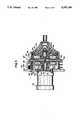
- FIG. 1is a side view of a pump mounted on a console
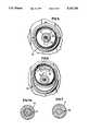
- FIG. 2is a front view of a pump
- FIG. 3is a cross section view of a pump mounted on a console
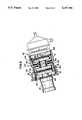
- FIG. 4is a cross section of an illustrative embodiment of the invention.
- FIG. 5is a front view of the console adaptor housing of FIG. 4 in the mounted position
- FIG. 6is a front view of the console adaptor housing of FIG. 4 in the unmounted position
- FIG. 7 and 7Aare a cross sections of a motor drive shaft assemblies for the illustrative embodiment of FIG. 4;
- FIG. 8is a cross section view of an illustrative embodiment of the invention.
- FIG. 9is a cross section view of an illustrative embodiment of the invention.
- FIG. 10is a cross section view of an illustrative embodiment of the invention.
- FIG. 11is a cross section view of an illustrative embodiment of the invention.
- FIG. 12is a cross section view of an illustrative embodiment of the invention.
- FIG. 13is a cross section view of an illustrative embodiment of the invention.
- FIG. 1shows a prior art kinetic pump 10 attached to a prior art pump control console 12.
- the consolehas a receiver 14 which connects the console 12 with the pump 10.
- the tubing coupler 16 located on the pump 10connects the pump to the patients arterial cannula to receive input blood flow.
- the output bloodflows from the tubing coupler 18 shown on FIG. 2 to the patient cannula.
- the two figures taken togethershow the generally circular form of the pump 10.
- FIG. 3shows a cross-section of the receiver 14, the pump 10, and a portion of the console 12.
- the console wall 20provides a mounting surface for the pump motor 22.
- the pumpis attached through the use of a plurality of screws shown in the figure as 24 and 25.
- the receiver 14is connected to this wall 20 through the use of screws shown in the figure at 26.
- the receiver 14has a detent fixture shown at 28, which engages the pump 10 to retain the pump in the receiver.
- the detent 28includes a prong 30 coupled to a thumb slide 32. These elements engage with the pump 10 through the action of the spring 34.
- the detent structurecooperates with a slot or convolution at the periphery of the backing plate in the receiver 14 to retain the pump flange 38.
- the pump 10has a mounting flange 38 formed in the backing plate 40.
- the backing platejoins to the pump housing 42.
- a rotator assembly shown as 44Within the vessel formed by the backing plate and housing there is a rotator assembly shown as 44.
- the rotatoris free to revolve around an axis defined by the shaft 49.
- This shaft 49is rigidly attached to the backing plate 40.
- Sealed cartridge bearing 48couple the rotator 44 to the shaft 49.
- Drive magnets 46positioned within a chamber 11 formed by the backing plate 40 and the rotator 44. This form of construction provides a pump interior which is smooth and biocompatible, for safe handling of the blood.
- the motor 22provides motive power to the pump 10.
- the preferred form of coupling powerrepresented by this prior art structure. As shown in the figure, driving magnets 50 located near the driven magnets 46 to transmit torque, to the rotator.
- the pump motor shaft 52has a flat formed on it to receive a setscrew 54.
- the setscrewconnects the drive-hub 56 to the driving magnets 50.
- FIG. 4shows a coupler constructed in accordance with the teaching of the present invention.
- the couplerprovides for the remote placement of the pump near the patient.
- the pumphowever is controlled by the console.
- a flexible shaft 58is used to connect the console to the pump.
- This couplerhas a pump adaptor designated 62 and has a console adaptor designated as 60.
- This couplerprovides for 1:1 power transmission from the console mounted pump motor 22 to the rotator 44.
- the console adaptor 60provides a flange 64 to mate with the annular recess 36 located in the console receiver 14.
- the flangehas recessed groove 66 which engages the prong 30 of the detent 28.
- a recess 68 provided in the console adapterpermits access to the setscrew 70.
- a collar 72engages the motor shaft 52 of the pump motor 22 to transmit power to the flexible shaft 58.
- a flexible sheath 70surrounds the shaft 58.
- a bushing designated 74provides connection between the flexible shaft 58 and the sheath 70 to the pump adaptor 60.
- the bushingis mounted in a longitudinal slot 78 formed in the console adaptor housing 76.
- the operatorfirst slides the collar 72 onto the motor shaft 52.
- the annular flange 64 of the console adaptor housingis positioned into the recess 36.
- the detent 28will engage the recessed groove 66.
- the operatorwill tighten the setscrew 70 to secure the collar 72 to the shaft 52. Once this operation has been completed the operator may tighten the bushing retaining nut 80.
- FIGS. 7 and 7atwo examples of alternate structure are shown.
- a broached collarmates with motor shaft without the use of a set screw.
- a broached spline collar 73is used with a splined motor shaft 51.
- the kinetic pump shown in phantom view in FIG. 4mounts to the pump receptacle 82 through the use of a helical fitting. This is shown by helical threads 84 formed in the receptacle. It should be appreciated that other forms of mounting are contemplated within the scope of this invention. For example, FIG. 8 shows a bayonet type of pump fitting which will be discussed in connection with that drawing.
- the pump receptacle housing 82contains a thin nonferrous cover 86 mounted within an annular recess 88 to separate the remote drive plate 90 from the pump backing plate.
- FIG. 8shows a coupler 93, having a console adaptor 92 and a pump receptacle 94.
- the magnetic driver 55remains unchanged.
- an intermediate power transfer assembly 96connects the drive motor 22 to the kinetic pump.
- a magnetic driver 55placed close to a complimentary drive receiver 98.
- the drive receiver 98mounted on a shaft 100 which rides in a bushing 102.
- a cooperating magnetic driver 104mounted on the shaft 100 to transmit power to a kinetic pump located in the pump receptacle 94.
- the housing 91includes a flange 106 to mate with the annular recess 36 located in the console receiver 14.
- the flangehas recessed groove 66 which engages the prong of the detent 28.
- the couplermay be inserted into the console as though it were a pump, which is a familiar operating room procedure.
- the pump receptacle portion of the couplerreceives the cylindrical base of a kinetic pump. This base member is retained through the use of a bayonet fitting which includes a slot 108 which is fabricated in the housing 91.
- Magnet to magnet adaptionis required when the console and pump have differing pole pieces which prevent the reliable transfer of power.
- FIG. 9shows an alternate form of magnet to magnet adaptor.
- the magnet assembly 110 located in the housing 112floats on a hydrodynamic bearing surfaces 118 and 116. These bearing surfaces maintain the position of the magnet assembly 110 in the cavity.
- a fluid fitting 114is provided to fill the cavity with a lubricating fluid to operate the hydrodynamic bearings. It is contemplated that the magnet assembly will be formed from first 116 and second 118 pole pieces. If the number of magnetic domains differs between the pole pieces, a magnetic permeable barrier 120 should be placed between them. The purpose of the barrier is to shunt the magnetic fields so that the two pole pieces do not interfere with each other.
- console motor 22connects with a magnetic driver 55.
- the driveris placed in close proximity to the first pole piece. This arrangement results in good torque transfer from the console to the coupler.
- the number of magnetic domains on the second pole pieceis selected to match the number used in the compatible pump.
- FIGS. 8 and 9the end-play of the pole pieces is controlled by thrust buttons 124 and 126.
- Thrust button 124cooperates with cover 86 in the embodiment shown in FIG. 8.
- FIG. 9shows an embodiment were the thrust button 128 abuts with a first coupler cover 130.
- the thrust button 130abut with a second coupler cover 131.
- the coupler covers and the housing 132define the magnet chamber 134.
- FIG. 10shows a coupler 138 which includes a console adaptor 140 comprising an annular flange 142 for engaging the console recess 36.
- the flange 142has a circumferential groove 144 to accept the console mounted detent 28.
- the pump receptacle 146has a conical surface 150 to align the kinetic pump with the drive magnets 50.
- the pumpmay be held or secured through the use of a pin lock structure comprising a pump mounted pin and a lock groove 152 which has a generally horizontal retention surface, or by a spring loaded clamping device 147 which captures its flangs.
- FIG. 12shows a coupler 154 which has structure to reverse direction of rotation.
- the couplerincludes driven magnets 156 in an eccentric position to reverse the direction of rotation of the output shaft.
- the driven magnetsare located in close proximity to the driving magnets 50.
- the driving magnets 50are connected to the console motor 22 as described in connection with earlier figures.
- Axial end play of the driven magnets 156is controlled with a thrust button 158 located on the driven magnets.
- the axis of rotation of the driven magnetsis displaced from the axis of rotation of the console motor. This displacement causes the direction of rotation to be reversed.
- the output shaft 158may be used to drive a flexible shaft as shown in FIG. 4 or may alternatively be used to drive a shaft driven pump as shown in FIG. 11.
- FIG. 11shows an adapter 148 which spaces a shaft driven pump 150 from the console.
- the coupler 148has a flange 152 which may be rotated into engagement with the recess 36.
- the pump shaft 71may be inserted onto the console motor shaft 52 and the pump maybe rotated into the receiver to secure it to the console.
- FIG. 13shows a coupler which includes a gear train power transfer mechanism.
- This gear trainmay be used to either increase or decrease the speed of rotation.
- This form of coupleris useful to match the console speed range with the requirements of the pump.
- the conventional pump control consoleoffers variable speed motor control over a wide range. However, some types of kinetic pumps operate at nominal speeds which do not overlap with the motor speeds available from the console. It should also be understood that gear trains of the type disclosed may be used to reverse the direction of rotation as taught by FIG. 12. The use of gears for the power transfer mechanism is preferred if the pump has significant torque requirements.
- a first gear 160is mounted on the motor shaft 52. This gear transfers power to a second gear 162 located on an intermediary shaft 163.
- the shaftis journaled in a bushing 164.
- the bushingis attached to the housing 166.
- a secondary gear trainwhich includes a third 168 and fourth 170 gear couple power to the magnet pole piece 172.
- the driving pole piece 172is concentric with the pump receptacle.
- the gear ratios selectedwould depend on the requirements of the kinetic pump being driven. The selection of kinetic pumps is not restricted to the type shown since other pumps having vanes in the combination with smooth converging rotators may be used with out departing from the spirit and scope of the invention.
Landscapes
- Health & Medical Sciences (AREA)
- Engineering & Computer Science (AREA)
- Heart & Thoracic Surgery (AREA)
- Mechanical Engineering (AREA)
- Cardiology (AREA)
- General Health & Medical Sciences (AREA)
- Veterinary Medicine (AREA)
- Hematology (AREA)
- Life Sciences & Earth Sciences (AREA)
- Animal Behavior & Ethology (AREA)
- Anesthesiology (AREA)
- Public Health (AREA)
- Biomedical Technology (AREA)
- General Engineering & Computer Science (AREA)
- Physics & Mathematics (AREA)
- Optics & Photonics (AREA)
- Fluid Mechanics (AREA)
- Pulmonology (AREA)
- Power Engineering (AREA)
- External Artificial Organs (AREA)
Abstract
Description
This is a division of application Ser. No. 07/389,634, filed Aug. 4, 1989, now U.S. Pat. No. 5,021,048.
This invention relates to blood perfusion pumps. A coupler for connecting a kinetic pump to a perfusion control console is described.
Blood is a fragile material which must be handled carefully. Early efforts at pumping blood in support of surgical procedures involved the use of the peristaltic or roller pump. This type of pump is easy to manufacture from biocompatible materials. This type of pump is also easy to control with simple motor controllers. However, these and other positive displacement pumps are inadequate when used to support some surgical procedures. The principal drawbacks of such pumps are the generation of air emboli, the disruption of tubing connectors and the fracture of pump tubing.
In response to these defects in the prior art, a new type of pump was introduced. U.S. Pat. No. 3,647,324 to Rafferty, E. et al. describes this new type of rotary pump. This type of pump has no vanes or impellers and is now commonly called a kinetic pump. The kinetic pump provides a smooth surface rotator which moves blood from a central inlet to the periphery of a pump housing. Although the angular velocity of the blood within the pump is essentially constant, the linear velocity continues to increase as the radial distance from the inlet increases. To preserve the flow pattern through the pump, the rotators converge so that rotator passages remain constant in cross sectional area. The spacing between the rotator passages varies as an inverse function of the radial distance from the rotator axis. This geometry of the kinetic pump results in the principal benefits of such pumps which are the prevention of cavitation, and the prevention of over pressurization of the blood.
The earliest versions of these pumps were powered by internal motor structures as shown in U.S. Pat. No. 4,037,984 to Rafferty, E. et al. An alterative to the internal motor is taught by U.S. Pat. No. 3,864,055 to Kletschka, which shows a drive shaft protruding from the pump housing.
The problems presented by each of these prior art approaches were overcome by the adoption of the driver apparatus shown in FIGS. 1, 2 and 3. Briefly, the pump is a disposable item which is discarded after a single use. As such, the pump is supplied as a sterilized and sealed unit. The pump is driven by the magnetic coupling of rotating drive magnets located in the control console and driven magnets embedded in the pump rotator.
Although the kinetic pump in its various forms has been successful in a wide variety of clinical settings, sophisticated control apparatus is required to monitor and supervise its operation. Currently, the control apparatus is supplied in a console which houses the drive motor and the supervisory electronics. The modern console may further include RPM monitor and control apparatus, along with pressure and flow monitoring apparatus.
The pump is mounted directly on the console in view of the physician or remotely from the drive console at or near the patient. By locating the pump close to the patient the amount of tubing required to hook the kinetic pump into the patients vascular system is reduced. In either location, the pump is driven magnetically. Typically the pump is placed into a pump receiver located on either, the console or on a remote driver unit.
Each manufacturer has a specialized pump design which renders certain combinations of pumps and consoles incompatible. This strategy prevents the use of incompatible systems and therefore provides additional protection to the patients.
Couplers in accordance with the present invention, adapt the pump control console to a variety of otherwise incompatible pumps. To accomplish this objective, power transmission structures are incorporated into the coupler. These structures match the power transmission requirements of the pump with the consoles output. Depending upon the pump, the coupler may include gear trains or other speed transformation structures to adapt the rotational speed and direction of the console to the pump.
In the drawings, like reference numerals indicate corresponding structure throughout the several views in which,
FIG. 1 is a side view of a pump mounted on a console;
FIG. 2 is a front view of a pump;
FIG. 3 is a cross section view of a pump mounted on a console;
FIG. 4 is a cross section of an illustrative embodiment of the invention;
FIG. 5 is a front view of the console adaptor housing of FIG. 4 in the mounted position;
FIG. 6 is a front view of the console adaptor housing of FIG. 4 in the unmounted position;
FIG. 7 and 7A are a cross sections of a motor drive shaft assemblies for the illustrative embodiment of FIG. 4;
FIG. 8 is a cross section view of an illustrative embodiment of the invention;
FIG. 9 is a cross section view of an illustrative embodiment of the invention;
FIG. 10 is a cross section view of an illustrative embodiment of the invention;
FIG. 11 is a cross section view of an illustrative embodiment of the invention;
FIG. 12 is a cross section view of an illustrative embodiment of the invention;
FIG. 13 is a cross section view of an illustrative embodiment of the invention.
FIG. 1, shows a prior artkinetic pump 10 attached to a prior artpump control console 12. The console has areceiver 14 which connects theconsole 12 with thepump 10. In operation, thetubing coupler 16 located on thepump 10 connects the pump to the patients arterial cannula to receive input blood flow. The output blood flows from thetubing coupler 18 shown on FIG. 2 to the patient cannula. The two figures taken together show the generally circular form of thepump 10.
FIG. 3 shows a cross-section of thereceiver 14, thepump 10, and a portion of theconsole 12. Theconsole wall 20 provides a mounting surface for thepump motor 22. The pump is attached through the use of a plurality of screws shown in the figure as 24 and 25. Thereceiver 14 is connected to thiswall 20 through the use of screws shown in the figure at 26.
Thereceiver 14 has a detent fixture shown at 28, which engages thepump 10 to retain the pump in the receiver. Thedetent 28 includes a prong 30 coupled to athumb slide 32. These elements engage with thepump 10 through the action of thespring 34. The detent structure cooperates with a slot or convolution at the periphery of the backing plate in thereceiver 14 to retain thepump flange 38.
Thepump 10 has a mountingflange 38 formed in the backing plate 40. The backing plate joins to the pump housing 42. Within the vessel formed by the backing plate and housing there is a rotator assembly shown as 44. The rotator is free to revolve around an axis defined by the shaft 49. This shaft 49 is rigidly attached to the backing plate 40. Sealed cartridge bearing 48 couple the rotator 44 to the shaft 49. Drivemagnets 46 positioned within a chamber 11 formed by the backing plate 40 and the rotator 44. This form of construction provides a pump interior which is smooth and biocompatible, for safe handling of the blood.
Themotor 22 provides motive power to thepump 10. The preferred form of coupling power represented by this prior art structure. As shown in the figure, drivingmagnets 50 located near the drivenmagnets 46 to transmit torque, to the rotator.
As shown in FIG. 3 thepump motor shaft 52 has a flat formed on it to receive asetscrew 54. The setscrew connects the drive-hub 56 to the drivingmagnets 50.
FIG. 4 shows a coupler constructed in accordance with the teaching of the present invention. The coupler provides for the remote placement of the pump near the patient. The pump however is controlled by the console. To achieve this objective aflexible shaft 58 is used to connect the console to the pump. This coupler has a pump adaptor designated 62 and has a console adaptor designated as 60. This coupler provides for 1:1 power transmission from the console mountedpump motor 22 to the rotator 44.
Theconsole adaptor 60 provides aflange 64 to mate with theannular recess 36 located in theconsole receiver 14. The flange has recessed groove 66 which engages the prong 30 of thedetent 28. Arecess 68 provided in the console adapter permits access to thesetscrew 70. Acollar 72 engages themotor shaft 52 of thepump motor 22 to transmit power to theflexible shaft 58. Aflexible sheath 70 surrounds theshaft 58. A bushing designated 74 provides connection between theflexible shaft 58 and thesheath 70 to thepump adaptor 60. Preferably the bushing is mounted in alongitudinal slot 78 formed in theconsole adaptor housing 76.
To use this coupler the operator first slides thecollar 72 onto themotor shaft 52. Next, theannular flange 64 of the console adaptor housing is positioned into therecess 36. During this operation thedetent 28 will engage the recessed groove 66. Next, the operator will tighten thesetscrew 70 to secure thecollar 72 to theshaft 52. Once this operation has been completed the operator may tighten thebushing retaining nut 80.
Alternate forms of mechanical connection between the motor and the collar may be employed without departing from the scope of this invention. In FIGS. 7 and 7a two examples of alternate structure are shown. In FIG. 7 a broached collar mates with motor shaft without the use of a set screw. Similarly a broachedspline collar 73 is used with asplined motor shaft 51.
The kinetic pump shown in phantom view in FIG. 4 mounts to thepump receptacle 82 through the use of a helical fitting. This is shown byhelical threads 84 formed in the receptacle. It should be appreciated that other forms of mounting are contemplated within the scope of this invention. For example, FIG. 8 shows a bayonet type of pump fitting which will be discussed in connection with that drawing. Thepump receptacle housing 82 contains a thinnonferrous cover 86 mounted within anannular recess 88 to separate theremote drive plate 90 from the pump backing plate.
FIG. 8 shows a coupler 93, having aconsole adaptor 92 and apump receptacle 94. In this embodiment of the invention themagnetic driver 55 remains unchanged. However, an intermediate power transfer assembly 96 connects thedrive motor 22 to the kinetic pump. Amagnetic driver 55 placed close to acomplimentary drive receiver 98. Thedrive receiver 98 mounted on ashaft 100 which rides in abushing 102. A cooperatingmagnetic driver 104 mounted on theshaft 100 to transmit power to a kinetic pump located in thepump receptacle 94. The housing 91 includes a flange 106 to mate with theannular recess 36 located in theconsole receiver 14. The flange has recessed groove 66 which engages the prong of thedetent 28. This is a highly desirable form of coupling because it requires no modification of the console itself. Additionally the coupler may be inserted into the console as though it were a pump, which is a familiar operating room procedure. The pump receptacle portion of the coupler receives the cylindrical base of a kinetic pump. This base member is retained through the use of a bayonet fitting which includes a slot 108 which is fabricated in the housing 91.
Magnet to magnet adaption is required when the console and pump have differing pole pieces which prevent the reliable transfer of power.
One drawback with the system shown in FIG. 8 is introduction of an additional bearing surface in the power transmission system. It is undesirable to add components where they do not offer an improved operational result.
FIG. 9 shows an alternate form of magnet to magnet adaptor. In contrast to the system of FIG. 8 there is no bearing support shaft. Themagnet assembly 110 located in thehousing 112 floats on a hydrodynamic bearing surfaces 118 and 116. These bearing surfaces maintain the position of themagnet assembly 110 in the cavity. A fluid fitting 114 is provided to fill the cavity with a lubricating fluid to operate the hydrodynamic bearings. It is contemplated that the magnet assembly will be formed from first 116 and second 118 pole pieces. If the number of magnetic domains differs between the pole pieces, a magneticpermeable barrier 120 should be placed between them. The purpose of the barrier is to shunt the magnetic fields so that the two pole pieces do not interfere with each other. Good torque transfer between a driving magnet and a driven magnet requires matching pole pieces. In this embodiment theconsole motor 22 connects with amagnetic driver 55. The driver is placed in close proximity to the first pole piece. This arrangement results in good torque transfer from the console to the coupler. The number of magnetic domains on the second pole piece is selected to match the number used in the compatible pump.
In the embodiments shown in FIGS. 8 and 9 the end-play of the pole pieces is controlled bythrust buttons Thrust button 124 cooperates withcover 86 in the embodiment shown in FIG. 8. FIG. 9 shows an embodiment were thethrust button 128 abuts with afirst coupler cover 130. Similarly, thethrust button 130 abut with asecond coupler cover 131. The coupler covers and thehousing 132 define themagnet chamber 134.
FIG. 10 shows acoupler 138 which includes aconsole adaptor 140 comprising anannular flange 142 for engaging theconsole recess 36. Theflange 142 has acircumferential groove 144 to accept the console mounteddetent 28. Thepump receptacle 146 has aconical surface 150 to align the kinetic pump with thedrive magnets 50. The pump may be held or secured through the use of a pin lock structure comprising a pump mounted pin and alock groove 152 which has a generally horizontal retention surface, or by a spring loadedclamping device 147 which captures its flangs.
FIG. 12 shows acoupler 154 which has structure to reverse direction of rotation. The coupler includes drivenmagnets 156 in an eccentric position to reverse the direction of rotation of the output shaft. The driven magnets are located in close proximity to the drivingmagnets 50. The drivingmagnets 50 are connected to theconsole motor 22 as described in connection with earlier figures. Axial end play of the drivenmagnets 156 is controlled with athrust button 158 located on the driven magnets. The axis of rotation of the driven magnets is displaced from the axis of rotation of the console motor. This displacement causes the direction of rotation to be reversed. It should be appreciated that theoutput shaft 158 may be used to drive a flexible shaft as shown in FIG. 4 or may alternatively be used to drive a shaft driven pump as shown in FIG. 11.
FIG. 11 shows anadapter 148 which spaces a shaft drivenpump 150 from the console. Thecoupler 148 has aflange 152 which may be rotated into engagement with therecess 36. Thepump shaft 71 may be inserted onto theconsole motor shaft 52 and the pump maybe rotated into the receiver to secure it to the console.
FIG. 13 shows a coupler which includes a gear train power transfer mechanism. This gear train may be used to either increase or decrease the speed of rotation. This form of coupler is useful to match the console speed range with the requirements of the pump. The conventional pump control console offers variable speed motor control over a wide range. However, some types of kinetic pumps operate at nominal speeds which do not overlap with the motor speeds available from the console. It should also be understood that gear trains of the type disclosed may be used to reverse the direction of rotation as taught by FIG. 12. The use of gears for the power transfer mechanism is preferred if the pump has significant torque requirements. In the embodiment shown in FIG. 13 a first gear 160 is mounted on themotor shaft 52. This gear transfers power to asecond gear 162 located on anintermediary shaft 163. The shaft is journaled in abushing 164. The bushing is attached to the housing 166. A secondary gear train which includes a third 168 and fourth 170 gear couple power to themagnet pole piece 172. Thedriving pole piece 172 is concentric with the pump receptacle. The gear ratios selected would depend on the requirements of the kinetic pump being driven. The selection of kinetic pumps is not restricted to the type shown since other pumps having vanes in the combination with smooth converging rotators may be used with out departing from the spirit and scope of the invention.
Claims (1)
1. Apparatus for pumping blood, comprising:
a pump controller console having a motor and having a pump receiver; said pump receiver including detent means for securing flanges and an annular recess for retaining flanges;
kinetic pump means for imparting kinetic energy to said blood; said pump means including rotator means for increasing the angular velocity of said blood; drive magnet means embedded in said rotator means adapted for coupling energy to said rotator;
coupler means for interconnecting said kinetic pump to said console; said coupler means including a pump receptacle and a console adapter, the console adapter comprising an annular housing 76 having, a peripheral flange 64 to mate with said annular recess on said console pump receiver 14 and having a recessed slot 66 to engage said detent on said console pump receiver; power transfer means having a bushing 74 for coupling to a flexible shaft 58 located in said annular housing 76 and having coupling means 72 for connection to said motor.
Priority Applications (1)
| Application Number | Priority Date | Filing Date | Title |
|---|---|---|---|
| US07/638,366US5147186A (en) | 1989-08-04 | 1991-01-04 | Blood pump drive system |
Applications Claiming Priority (2)
| Application Number | Priority Date | Filing Date | Title |
|---|---|---|---|
| US07/389,634US5021048A (en) | 1989-08-04 | 1989-08-04 | Blood pump drive system |
| US07/638,366US5147186A (en) | 1989-08-04 | 1991-01-04 | Blood pump drive system |
Related Parent Applications (1)
| Application Number | Title | Priority Date | Filing Date |
|---|---|---|---|
| US07/389,634DivisionUS5021048A (en) | 1989-08-04 | 1989-08-04 | Blood pump drive system |
Publications (1)
| Publication Number | Publication Date |
|---|---|
| US5147186Atrue US5147186A (en) | 1992-09-15 |
Family
ID=27012781
Family Applications (1)
| Application Number | Title | Priority Date | Filing Date |
|---|---|---|---|
| US07/638,366Expired - LifetimeUS5147186A (en) | 1989-08-04 | 1991-01-04 | Blood pump drive system |
Country Status (1)
| Country | Link |
|---|---|
| US (1) | US5147186A (en) |
Cited By (91)
| Publication number | Priority date | Publication date | Assignee | Title |
|---|---|---|---|---|
| US5411378A (en)* | 1992-09-08 | 1995-05-02 | Sipin; Anatole J. | Orbiting fluid pump |
| US5786816A (en)* | 1995-10-20 | 1998-07-28 | Araxsys, Inc. | Method and apparatus for graphical user interface-based and variable result healthcare plan |
| US5826237A (en)* | 1995-10-20 | 1998-10-20 | Araxsys, Inc. | Apparatus and method for merging medical protocols |
| US5850221A (en)* | 1995-10-20 | 1998-12-15 | Araxsys, Inc. | Apparatus and method for a graphic user interface in a medical protocol system |
| US5886693A (en)* | 1995-10-20 | 1999-03-23 | Araxsys, Inc. | Method and apparatus for processing data across a computer network |
| US5894273A (en)* | 1996-08-26 | 1999-04-13 | Fairway Medical Technologies, Inc. | Centrifugal blood pump driver apparatus |
| US5919125A (en)* | 1997-07-11 | 1999-07-06 | Cobe Laboratories, Inc. | Centrifuge bowl for autologous blood salvage |
| US5976388A (en)* | 1997-05-20 | 1999-11-02 | Cobe Cardiovascular Operating Co., Inc. | Method and apparatus for autologous blood salvage |
| WO2000019097A1 (en)* | 1998-09-30 | 2000-04-06 | A-Med Systems, Inc. | Blood pump system with magnetic cable drive |
| US6116862A (en)* | 1996-06-25 | 2000-09-12 | Medos Medizintechnik Gmbh | Blood pump |
| US6152704A (en)* | 1998-09-30 | 2000-11-28 | A-Med Systems, Inc. | Blood pump with turbine drive |
| US6210133B1 (en) | 1998-09-30 | 2001-04-03 | A-Med Systems, Inc. | Blood pump with sterile motor housing |
| US20030139643A1 (en)* | 1997-09-24 | 2003-07-24 | The Cleveland Clinic Foundation | Flow controlled blood pump system |
| US20030185677A1 (en)* | 2000-01-21 | 2003-10-02 | Pingchou Xia | Automobile water pump with permanent magnetic coupling |
| US20040197223A1 (en)* | 2003-01-14 | 2004-10-07 | Olsen Robert W. | Active air removal system operating modes of an extracorporeal blood circuit |
| US20040195178A1 (en)* | 2003-01-14 | 2004-10-07 | Carpenter Walter L. | Extracorporeal blood circuit priming system and method |
| US20040220509A1 (en)* | 2003-01-14 | 2004-11-04 | Olsen Robert W. | Active air removal from an extracorporeal blood circuit |
| US20040217054A1 (en)* | 2003-01-14 | 2004-11-04 | Olsen Robert W. | Extracorporeal blood circuit air removal system and method |
| US20050063860A1 (en)* | 2003-01-14 | 2005-03-24 | Carpenter Walter L. | Disposable, integrated, extracorporeal blood circuit |
| US20060290464A1 (en)* | 1996-09-30 | 2006-12-28 | Willems Richard M | Network communication and message protocol for a medical perfusion system |
| US7927068B2 (en) | 2004-09-17 | 2011-04-19 | Thoratec Corporation | Expandable impeller pump |
| US7998054B2 (en) | 1997-10-09 | 2011-08-16 | Thoratec Corporation | Implantable heart assist system and method of applying same |
| US8118724B2 (en) | 2003-09-18 | 2012-02-21 | Thoratec Corporation | Rotary blood pump |
| US8317672B2 (en) | 2010-11-19 | 2012-11-27 | Kensey Nash Corporation | Centrifuge method and apparatus |
| US8394006B2 (en) | 2010-11-19 | 2013-03-12 | Kensey Nash Corporation | Centrifuge |
| US8469871B2 (en) | 2010-11-19 | 2013-06-25 | Kensey Nash Corporation | Centrifuge |
| US8485961B2 (en) | 2011-01-05 | 2013-07-16 | Thoratec Corporation | Impeller housing for percutaneous heart pump |
| US8535211B2 (en) | 2009-07-01 | 2013-09-17 | Thoratec Corporation | Blood pump with expandable cannula |
| US8556794B2 (en) | 2010-11-19 | 2013-10-15 | Kensey Nash Corporation | Centrifuge |
| US8591393B2 (en) | 2011-01-06 | 2013-11-26 | Thoratec Corporation | Catheter pump |
| US8597170B2 (en) | 2011-01-05 | 2013-12-03 | Thoratec Corporation | Catheter pump |
| US20140010672A1 (en)* | 2012-07-09 | 2014-01-09 | Roger A. Naidyhorski | Reducing centrifugal pump bearing wear through dynamic magnetic coupling |
| EP2366412A3 (en)* | 2007-10-08 | 2014-03-26 | Ais Gmbh Aachen Innovative Solutions | Catheter device |
| US8721517B2 (en) | 2012-05-14 | 2014-05-13 | Thoratec Corporation | Impeller for catheter pump |
| US8821365B2 (en) | 2009-07-29 | 2014-09-02 | Thoratec Corporation | Rotation drive device and centrifugal pump apparatus using the same |
| US8827661B2 (en) | 2008-06-23 | 2014-09-09 | Thoratec Corporation | Blood pump apparatus |
| US8870733B2 (en) | 2010-11-19 | 2014-10-28 | Kensey Nash Corporation | Centrifuge |
| US9067005B2 (en) | 2008-12-08 | 2015-06-30 | Thoratec Corporation | Centrifugal pump apparatus |
| US9068572B2 (en) | 2010-07-12 | 2015-06-30 | Thoratec Corporation | Centrifugal pump apparatus |
| US9133854B2 (en) | 2010-03-26 | 2015-09-15 | Thoratec Corporation | Centrifugal blood pump device |
| US9132215B2 (en) | 2010-02-16 | 2015-09-15 | Thoratee Corporation | Centrifugal pump apparatus |
| US9138518B2 (en) | 2011-01-06 | 2015-09-22 | Thoratec Corporation | Percutaneous heart pump |
| US9308302B2 (en) | 2013-03-15 | 2016-04-12 | Thoratec Corporation | Catheter pump assembly including a stator |
| US9327067B2 (en) | 2012-05-14 | 2016-05-03 | Thoratec Corporation | Impeller for catheter pump |
| US9358329B2 (en) | 2012-07-03 | 2016-06-07 | Thoratec Corporation | Catheter pump |
| US9366261B2 (en) | 2012-01-18 | 2016-06-14 | Thoratec Corporation | Centrifugal pump device |
| US9364592B2 (en) | 2004-09-17 | 2016-06-14 | The Penn State Research Foundation | Heart assist device with expandable impeller pump |
| US9371826B2 (en) | 2013-01-24 | 2016-06-21 | Thoratec Corporation | Impeller position compensation using field oriented control |
| US9381288B2 (en) | 2013-03-13 | 2016-07-05 | Thoratec Corporation | Fluid handling system |
| US9382908B2 (en) | 2010-09-14 | 2016-07-05 | Thoratec Corporation | Centrifugal pump apparatus |
| US9381285B2 (en) | 2009-03-05 | 2016-07-05 | Thoratec Corporation | Centrifugal pump apparatus |
| US9404505B2 (en) | 2008-12-05 | 2016-08-02 | Ecp Entwicklungsgesellschaft Mbh | Fluid pump with a rotor |
| US9410549B2 (en) | 2009-03-06 | 2016-08-09 | Thoratec Corporation | Centrifugal pump apparatus |
| US9421311B2 (en) | 2012-07-03 | 2016-08-23 | Thoratec Corporation | Motor assembly for catheter pump |
| US9446179B2 (en) | 2012-05-14 | 2016-09-20 | Thoratec Corporation | Distal bearing support |
| US9512852B2 (en) | 2006-03-31 | 2016-12-06 | Thoratec Corporation | Rotary blood pump |
| US9556873B2 (en) | 2013-02-27 | 2017-01-31 | Tc1 Llc | Startup sequence for centrifugal pump with levitated impeller |
| US9623161B2 (en) | 2014-08-26 | 2017-04-18 | Tc1 Llc | Blood pump and method of suction detection |
| US9675738B2 (en) | 2015-01-22 | 2017-06-13 | Tc1 Llc | Attachment mechanisms for motor of catheter pump |
| US9675739B2 (en) | 2015-01-22 | 2017-06-13 | Tc1 Llc | Motor assembly with heat exchanger for catheter pump |
| US9713663B2 (en) | 2013-04-30 | 2017-07-25 | Tc1 Llc | Cardiac pump with speed adapted for ventricle unloading |
| US9759237B2 (en) | 2010-05-17 | 2017-09-12 | Ecp Entwicklungsgesellschaft Mbh | Pump arrangement |
| US9771801B2 (en) | 2010-07-15 | 2017-09-26 | Ecp Entwicklungsgesellschaft Mbh | Rotor for a pump, produced with a first elastic material |
| US9770543B2 (en) | 2015-01-22 | 2017-09-26 | Tc1 Llc | Reduced rotational mass motor assembly for catheter pump |
| US9827356B2 (en) | 2014-04-15 | 2017-11-28 | Tc1 Llc | Catheter pump with access ports |
| US9833550B2 (en) | 2003-08-08 | 2017-12-05 | Abiomed Europe Gmbh | Intracardiac pumping device |
| US9850906B2 (en) | 2011-03-28 | 2017-12-26 | Tc1 Llc | Rotation drive device and centrifugal pump apparatus employing same |
| US9872947B2 (en) | 2012-05-14 | 2018-01-23 | Tc1 Llc | Sheath system for catheter pump |
| US9878079B2 (en) | 2007-10-08 | 2018-01-30 | Ais Gmbh Aachen Innovative Solutions | Catheter device |
| US9907890B2 (en) | 2015-04-16 | 2018-03-06 | Tc1 Llc | Catheter pump with positioning brace |
| US10029037B2 (en) | 2014-04-15 | 2018-07-24 | Tc1 Llc | Sensors for catheter pumps |
| US10052420B2 (en) | 2013-04-30 | 2018-08-21 | Tc1 Llc | Heart beat identification and pump speed synchronization |
| US10080871B2 (en) | 2012-12-21 | 2018-09-25 | Ecp Entwicklungsgesellschaft Mbh | Sheath assembly for insertion of a cord-shaped element, particularly a catheter, into the body of a patient |
| US10105475B2 (en) | 2014-04-15 | 2018-10-23 | Tc1 Llc | Catheter pump introducer systems and methods |
| US10117983B2 (en) | 2015-11-16 | 2018-11-06 | Tc1 Llc | Pressure/flow characteristic modification of a centrifugal pump in a ventricular assist device |
| US10125345B2 (en) | 2014-01-31 | 2018-11-13 | Dsm Ip Assets, B.V. | Adipose tissue centrifuge and method of use |
| US10166318B2 (en) | 2015-02-12 | 2019-01-01 | Tc1 Llc | System and method for controlling the position of a levitated rotor |
| US10245361B2 (en) | 2015-02-13 | 2019-04-02 | Tc1 Llc | Impeller suspension mechanism for heart pump |
| US10371152B2 (en) | 2015-02-12 | 2019-08-06 | Tc1 Llc | Alternating pump gaps |
| US10506935B2 (en) | 2015-02-11 | 2019-12-17 | Tc1 Llc | Heart beat identification and pump speed synchronization |
| US10525238B2 (en) | 2011-12-22 | 2020-01-07 | Ecp Entwicklungsgesellschaft Mbh | Sheath device for inserting a catheter |
| US10583232B2 (en) | 2014-04-15 | 2020-03-10 | Tc1 Llc | Catheter pump with off-set motor position |
| US10709828B2 (en) | 2011-12-22 | 2020-07-14 | Ecp Entwicklungsgesellschaft Mbh | Sheath device for inserting a catheter |
| US10874781B2 (en) | 2010-06-25 | 2020-12-29 | Ecp Entwicklungsgesellschaft Mbh | System for introducing a pump |
| US10874783B2 (en) | 2007-10-08 | 2020-12-29 | Ais Gmbh Aachen Innovative Solutions | Catheter device |
| US11077294B2 (en) | 2013-03-13 | 2021-08-03 | Tc1 Llc | Sheath assembly for catheter pump |
| US11219756B2 (en) | 2012-07-03 | 2022-01-11 | Tc1 Llc | Motor assembly for catheter pump |
| US11229786B2 (en) | 2012-05-14 | 2022-01-25 | Tc1 Llc | Impeller for catheter pump |
| US11850414B2 (en) | 2013-03-13 | 2023-12-26 | Tc1 Llc | Fluid handling system |
| US12337097B2 (en) | 2010-11-19 | 2025-06-24 | Dsm Ip Assets B.V. | Centrifuge |
| US12350483B2 (en) | 2016-07-21 | 2025-07-08 | Tc1 Llc | Fluid seals for catheter pump motor assembly |
Citations (28)
| Publication number | Priority date | Publication date | Assignee | Title |
|---|---|---|---|---|
| US413684A (en)* | 1889-10-29 | Rotary pump | ||
| US3085407A (en)* | 1962-03-20 | 1963-04-16 | Sprague Engineering Corp | Coupling means |
| US3089514A (en)* | 1961-07-12 | 1963-05-14 | Gustav H Sudmeier | Temperature-stabilized plumbing system |
| US3169486A (en)* | 1963-07-29 | 1965-02-16 | Duriron Co | Pumps |
| US3194165A (en)* | 1962-02-28 | 1965-07-13 | Sorlin Nils | Electric motor pump |
| US3221389A (en)* | 1964-09-22 | 1965-12-07 | Ind Tectonics Inc | Textile spindle |
| US3228344A (en)* | 1963-08-30 | 1966-01-11 | Trw Inc | Centrifugal impeller and method of making same |
| US3314512A (en)* | 1965-07-02 | 1967-04-18 | Borg Warner | Coupling device employing flexible hub assembly |
| US3368743A (en)* | 1965-04-12 | 1968-02-13 | Campagnie Electro Mecanique | Shaft construction for rotary machines |
| US3411450A (en)* | 1967-03-07 | 1968-11-19 | Little Giant Corp | Pump |
| US3470824A (en)* | 1968-09-12 | 1969-10-07 | Walbro Corp | Magnetic drive pump |
| US3487784A (en)* | 1967-10-26 | 1970-01-06 | Edson Howard Rafferty | Pumps capable of use as heart pumps |
| US3500754A (en)* | 1968-01-25 | 1970-03-17 | Loewe Pumpenfabrik Gmbh | Centrifugal pump units |
| US3608088A (en)* | 1969-04-17 | 1971-09-28 | Univ Minnesota | Implantable blood pump |
| US3638455A (en)* | 1970-07-08 | 1972-02-01 | Uniroyal Inc | Filament-wound resin torsion tubes with molded end splines |
| US3647324A (en)* | 1969-12-18 | 1972-03-07 | Edson Howard Rafferty | Electrically driven pumps capable of use as heart pumps |
| US3864055A (en)* | 1971-12-06 | 1975-02-04 | Harold D Kletschka | Pumps capable of use as heart pumps and blood pumps |
| US3890969A (en)* | 1974-01-21 | 1975-06-24 | Baxter Laboratories Inc | Cardiopulmonary bypass system |
| USRE28742E (en)* | 1967-10-26 | 1976-03-23 | Pumps capable of use as heart pumps | |
| US3957389A (en)* | 1967-10-26 | 1976-05-18 | Bio-Medicus, Inc. | Pumping apparatus and process characterized by gentle operation |
| US3970408A (en)* | 1967-10-26 | 1976-07-20 | Bio-Medicus, Inc. | Apparatus for use with delicate fluids |
| US4065234A (en)* | 1975-12-22 | 1977-12-27 | Nihon Kagaku Kizai Kabushiki Kaisha | Magnetically driven rotary pumps |
| US4135253A (en)* | 1976-11-30 | 1979-01-23 | Medtronic, Inc. | Centrifugal blood pump for cardiac assist |
| US4304532A (en)* | 1979-12-17 | 1981-12-08 | Mccoy Lee A | Pump having magnetic drive |
| US4643641A (en)* | 1984-09-10 | 1987-02-17 | Mici Limited Partnership Iv | Method and apparatus for sterilization of a centrifugal pump |
| US4678409A (en)* | 1984-11-22 | 1987-07-07 | Fuji Photo Film Co., Ltd. | Multiple magnetic pump system |
| US4722661A (en)* | 1985-10-09 | 1988-02-02 | Ngk Insulators, Ltd. | Magnetic-drive centrifugal pump |
| US4895557A (en)* | 1987-12-07 | 1990-01-23 | Nimbus Medical, Inc. | Drive mechanism for powering intravascular blood pumps |
- 1991
- 1991-01-04USUS07/638,366patent/US5147186A/ennot_activeExpired - Lifetime
Patent Citations (28)
| Publication number | Priority date | Publication date | Assignee | Title |
|---|---|---|---|---|
| US413684A (en)* | 1889-10-29 | Rotary pump | ||
| US3089514A (en)* | 1961-07-12 | 1963-05-14 | Gustav H Sudmeier | Temperature-stabilized plumbing system |
| US3194165A (en)* | 1962-02-28 | 1965-07-13 | Sorlin Nils | Electric motor pump |
| US3085407A (en)* | 1962-03-20 | 1963-04-16 | Sprague Engineering Corp | Coupling means |
| US3169486A (en)* | 1963-07-29 | 1965-02-16 | Duriron Co | Pumps |
| US3228344A (en)* | 1963-08-30 | 1966-01-11 | Trw Inc | Centrifugal impeller and method of making same |
| US3221389A (en)* | 1964-09-22 | 1965-12-07 | Ind Tectonics Inc | Textile spindle |
| US3368743A (en)* | 1965-04-12 | 1968-02-13 | Campagnie Electro Mecanique | Shaft construction for rotary machines |
| US3314512A (en)* | 1965-07-02 | 1967-04-18 | Borg Warner | Coupling device employing flexible hub assembly |
| US3411450A (en)* | 1967-03-07 | 1968-11-19 | Little Giant Corp | Pump |
| USRE28742E (en)* | 1967-10-26 | 1976-03-23 | Pumps capable of use as heart pumps | |
| US3487784A (en)* | 1967-10-26 | 1970-01-06 | Edson Howard Rafferty | Pumps capable of use as heart pumps |
| US3970408A (en)* | 1967-10-26 | 1976-07-20 | Bio-Medicus, Inc. | Apparatus for use with delicate fluids |
| US3957389A (en)* | 1967-10-26 | 1976-05-18 | Bio-Medicus, Inc. | Pumping apparatus and process characterized by gentle operation |
| US3500754A (en)* | 1968-01-25 | 1970-03-17 | Loewe Pumpenfabrik Gmbh | Centrifugal pump units |
| US3470824A (en)* | 1968-09-12 | 1969-10-07 | Walbro Corp | Magnetic drive pump |
| US3608088A (en)* | 1969-04-17 | 1971-09-28 | Univ Minnesota | Implantable blood pump |
| US3647324A (en)* | 1969-12-18 | 1972-03-07 | Edson Howard Rafferty | Electrically driven pumps capable of use as heart pumps |
| US3638455A (en)* | 1970-07-08 | 1972-02-01 | Uniroyal Inc | Filament-wound resin torsion tubes with molded end splines |
| US3864055A (en)* | 1971-12-06 | 1975-02-04 | Harold D Kletschka | Pumps capable of use as heart pumps and blood pumps |
| US3890969A (en)* | 1974-01-21 | 1975-06-24 | Baxter Laboratories Inc | Cardiopulmonary bypass system |
| US4065234A (en)* | 1975-12-22 | 1977-12-27 | Nihon Kagaku Kizai Kabushiki Kaisha | Magnetically driven rotary pumps |
| US4135253A (en)* | 1976-11-30 | 1979-01-23 | Medtronic, Inc. | Centrifugal blood pump for cardiac assist |
| US4304532A (en)* | 1979-12-17 | 1981-12-08 | Mccoy Lee A | Pump having magnetic drive |
| US4643641A (en)* | 1984-09-10 | 1987-02-17 | Mici Limited Partnership Iv | Method and apparatus for sterilization of a centrifugal pump |
| US4678409A (en)* | 1984-11-22 | 1987-07-07 | Fuji Photo Film Co., Ltd. | Multiple magnetic pump system |
| US4722661A (en)* | 1985-10-09 | 1988-02-02 | Ngk Insulators, Ltd. | Magnetic-drive centrifugal pump |
| US4895557A (en)* | 1987-12-07 | 1990-01-23 | Nimbus Medical, Inc. | Drive mechanism for powering intravascular blood pumps |
Cited By (226)
| Publication number | Priority date | Publication date | Assignee | Title |
|---|---|---|---|---|
| US5411378A (en)* | 1992-09-08 | 1995-05-02 | Sipin; Anatole J. | Orbiting fluid pump |
| US5786816A (en)* | 1995-10-20 | 1998-07-28 | Araxsys, Inc. | Method and apparatus for graphical user interface-based and variable result healthcare plan |
| US5826237A (en)* | 1995-10-20 | 1998-10-20 | Araxsys, Inc. | Apparatus and method for merging medical protocols |
| US5850221A (en)* | 1995-10-20 | 1998-12-15 | Araxsys, Inc. | Apparatus and method for a graphic user interface in a medical protocol system |
| US5886693A (en)* | 1995-10-20 | 1999-03-23 | Araxsys, Inc. | Method and apparatus for processing data across a computer network |
| US6116862A (en)* | 1996-06-25 | 2000-09-12 | Medos Medizintechnik Gmbh | Blood pump |
| US5894273A (en)* | 1996-08-26 | 1999-04-13 | Fairway Medical Technologies, Inc. | Centrifugal blood pump driver apparatus |
| US6137416A (en)* | 1996-08-26 | 2000-10-24 | Fairway Medical Technologies, Inc. | Method of controlling centrifugal pump |
| US7535336B2 (en) | 1996-09-30 | 2009-05-19 | Terumo Cardiovascular Systems Corporation | Network communication and message protocol for a medical perfusion system |
| US20060290464A1 (en)* | 1996-09-30 | 2006-12-28 | Willems Richard M | Network communication and message protocol for a medical perfusion system |
| US7843311B2 (en) | 1996-09-30 | 2010-11-30 | Terumo Cardiovascular Systems | Network communication and message protocol for a medical perfusion system |
| US20090163854A1 (en)* | 1996-09-30 | 2009-06-25 | Terumo Cardiovascular Systems Corporation | Network Communication and Message Protocol for a Medical Perfusion System |
| US5976388A (en)* | 1997-05-20 | 1999-11-02 | Cobe Cardiovascular Operating Co., Inc. | Method and apparatus for autologous blood salvage |
| US5919125A (en)* | 1997-07-11 | 1999-07-06 | Cobe Laboratories, Inc. | Centrifuge bowl for autologous blood salvage |
| US20030139643A1 (en)* | 1997-09-24 | 2003-07-24 | The Cleveland Clinic Foundation | Flow controlled blood pump system |
| US7998054B2 (en) | 1997-10-09 | 2011-08-16 | Thoratec Corporation | Implantable heart assist system and method of applying same |
| US6152704A (en)* | 1998-09-30 | 2000-11-28 | A-Med Systems, Inc. | Blood pump with turbine drive |
| US6210133B1 (en) | 1998-09-30 | 2001-04-03 | A-Med Systems, Inc. | Blood pump with sterile motor housing |
| WO2000019097A1 (en)* | 1998-09-30 | 2000-04-06 | A-Med Systems, Inc. | Blood pump system with magnetic cable drive |
| US20030185677A1 (en)* | 2000-01-21 | 2003-10-02 | Pingchou Xia | Automobile water pump with permanent magnetic coupling |
| US7204958B2 (en) | 2003-01-14 | 2007-04-17 | Medtronic, Inc. | Extracorporeal blood circuit air removal system and method |
| US20040217054A1 (en)* | 2003-01-14 | 2004-11-04 | Olsen Robert W. | Extracorporeal blood circuit air removal system and method |
| US7189352B2 (en) | 2003-01-14 | 2007-03-13 | Medtronic, Inc. | Extracorporeal blood circuit priming system and method |
| US7198751B2 (en) | 2003-01-14 | 2007-04-03 | Medtronic, Inc. | Disposable, integrated, extracorporeal blood circuit |
| US7201870B2 (en) | 2003-01-14 | 2007-04-10 | Medtronic, Inc. | Active air removal system operating modes of an extracorporeal blood circuit |
| US20050063860A1 (en)* | 2003-01-14 | 2005-03-24 | Carpenter Walter L. | Disposable, integrated, extracorporeal blood circuit |
| US20070140899A1 (en)* | 2003-01-14 | 2007-06-21 | Olsen Robert W | Active air removal system operating modes of an extracorporeal blood circuit |
| US20070140898A1 (en)* | 2003-01-14 | 2007-06-21 | Olsen Robert W | Extracorporeal blood circuit air removal system and method |
| US20070258856A1 (en)* | 2003-01-14 | 2007-11-08 | Olsen Robert W | Active air removal from an extracorporeal blood circuit |
| US7335334B2 (en) | 2003-01-14 | 2008-02-26 | Medtronic, Inc. | Active air removal from an extracorporeal blood circuit |
| US20040197223A1 (en)* | 2003-01-14 | 2004-10-07 | Olsen Robert W. | Active air removal system operating modes of an extracorporeal blood circuit |
| US20040195178A1 (en)* | 2003-01-14 | 2004-10-07 | Carpenter Walter L. | Extracorporeal blood circuit priming system and method |
| US7704455B2 (en) | 2003-01-14 | 2010-04-27 | Medtronic, Inc. | Active air removal system operating modes of an extracorporeal blood circuit |
| US7740800B2 (en) | 2003-01-14 | 2010-06-22 | Medtronic, Inc. | Extracorporeal blood circuit air removal system and method |
| US7829018B2 (en) | 2003-01-14 | 2010-11-09 | Medtronic, Inc. | Active air removal from an extracorporeal blood circuit |
| US20040220509A1 (en)* | 2003-01-14 | 2004-11-04 | Olsen Robert W. | Active air removal from an extracorporeal blood circuit |
| US11491320B2 (en) | 2003-08-08 | 2022-11-08 | Abiomed Europe Gmbh | Intracardiac pumping device |
| US12023477B2 (en) | 2003-08-08 | 2024-07-02 | Abiomed Europe Gmbh | Intracardiac pumping device |
| US9833550B2 (en) | 2003-08-08 | 2017-12-05 | Abiomed Europe Gmbh | Intracardiac pumping device |
| US9872948B2 (en) | 2003-08-08 | 2018-01-23 | Abiomed Europe Gmbh | Intracardiac pumping device |
| US8118724B2 (en) | 2003-09-18 | 2012-02-21 | Thoratec Corporation | Rotary blood pump |
| US8684902B2 (en) | 2003-09-18 | 2014-04-01 | Thoratec Corporation | Rotary blood pump |
| WO2005065741A1 (en) | 2003-12-22 | 2005-07-21 | Medtronic, Inc. | Active air removal from an extracorporeal blood circuit |
| US11434921B2 (en) | 2004-09-17 | 2022-09-06 | Tc1 Llc | Expandable impeller pump |
| US9717833B2 (en) | 2004-09-17 | 2017-08-01 | The Penn State Research Foundation | Heart assist device with expandable impeller pump |
| US9364593B2 (en) | 2004-09-17 | 2016-06-14 | The Penn State Research Foundation | Heart assist device with expandable impeller pump |
| US7927068B2 (en) | 2004-09-17 | 2011-04-19 | Thoratec Corporation | Expandable impeller pump |
| US9364592B2 (en) | 2004-09-17 | 2016-06-14 | The Penn State Research Foundation | Heart assist device with expandable impeller pump |
| US8992163B2 (en) | 2004-09-17 | 2015-03-31 | Thoratec Corporation | Expandable impeller pump |
| US10215187B2 (en) | 2004-09-17 | 2019-02-26 | Tc1 Llc | Expandable impeller pump |
| US8376707B2 (en) | 2004-09-17 | 2013-02-19 | Thoratec Corporation | Expandable impeller pump |
| US11428236B2 (en) | 2004-09-17 | 2022-08-30 | Tc1 Llc | Expandable impeller pump |
| US11708833B2 (en) | 2006-03-23 | 2023-07-25 | The Penn State Research Foundation | Heart assist device with expandable impeller pump |
| US12404858B2 (en) | 2006-03-23 | 2025-09-02 | The Penn State Research Foundation | Catheter blood pump heart assist device |
| US10864309B2 (en) | 2006-03-23 | 2020-12-15 | The Penn State Research Foundation | Heart assist device with expandable impeller pump |
| US10149932B2 (en) | 2006-03-23 | 2018-12-11 | The Penn State Research Foundation | Heart assist device with expandable impeller pump |
| US9512852B2 (en) | 2006-03-31 | 2016-12-06 | Thoratec Corporation | Rotary blood pump |
| US12364841B2 (en) | 2007-10-08 | 2025-07-22 | Ais Gmbh Aachen Innovative Solutions | Catheter device |
| US10874783B2 (en) | 2007-10-08 | 2020-12-29 | Ais Gmbh Aachen Innovative Solutions | Catheter device |
| US10980927B2 (en) | 2007-10-08 | 2021-04-20 | Ais Gmbh Aachen Innovative Solutions | Catheter device |
| US11583659B2 (en) | 2007-10-08 | 2023-02-21 | Ais Gmbh Aachen Innovative Solutions | Catheter device |
| EP2366412B1 (en) | 2007-10-08 | 2018-08-01 | Ais Gmbh Aachen Innovative Solutions | Catheter device |
| US10449276B2 (en) | 2007-10-08 | 2019-10-22 | Ais Gmbh Aachen Innovative Solutions | Catheter device |
| EP3431115A1 (en)* | 2007-10-08 | 2019-01-23 | Ais Gmbh Aachen Innovative Solutions | Catheter device |
| US10799624B2 (en) | 2007-10-08 | 2020-10-13 | Ais Gmbh Aachen Innovative Solutions | Catheter device |
| US10894115B2 (en) | 2007-10-08 | 2021-01-19 | Ais Gmbh Aachen Innovative Solutions | Catheter device |
| EP2366412A3 (en)* | 2007-10-08 | 2014-03-26 | Ais Gmbh Aachen Innovative Solutions | Catheter device |
| US11786700B2 (en) | 2007-10-08 | 2023-10-17 | Ais Gmbh Aachen Innovative Solutions | Catheter device |
| US10478539B2 (en) | 2007-10-08 | 2019-11-19 | Ais Gmbh Aachen Innovative Solutions | Catheter device |
| US11338124B2 (en) | 2007-10-08 | 2022-05-24 | Ais Gmbh Aachen Innovative Solutions | Catheter device |
| US11273301B2 (en) | 2007-10-08 | 2022-03-15 | Ais Gmbh Aachen Innovative Solutions | Catheter device |
| US11253693B2 (en) | 2007-10-08 | 2022-02-22 | Ais Gmbh Aachen Innovative Solutions | Catheter device |
| EP4534026A3 (en)* | 2007-10-08 | 2025-06-18 | Ais Gmbh Aachen Innovative Solutions | Catheter device |
| US11167124B2 (en) | 2007-10-08 | 2021-11-09 | Ais Gmbh Aachen Innovative Solutions | Catheter device |
| US9878079B2 (en) | 2007-10-08 | 2018-01-30 | Ais Gmbh Aachen Innovative Solutions | Catheter device |
| US9889242B2 (en) | 2007-10-08 | 2018-02-13 | Ais Gmbh Aachen Innovative Solutions | Catheter device |
| US11129978B2 (en) | 2007-10-08 | 2021-09-28 | Ais Gmbh Aachen Innovative Solutions | Catheter device |
| US11123539B2 (en) | 2007-10-08 | 2021-09-21 | Ais Gmbh Aachen Innovative Solutions | Catheter device |
| US9109601B2 (en) | 2008-06-23 | 2015-08-18 | Thoratec Corporation | Blood pump apparatus |
| US8827661B2 (en) | 2008-06-23 | 2014-09-09 | Thoratec Corporation | Blood pump apparatus |
| US9404505B2 (en) | 2008-12-05 | 2016-08-02 | Ecp Entwicklungsgesellschaft Mbh | Fluid pump with a rotor |
| US10662967B2 (en) | 2008-12-05 | 2020-05-26 | Ecp Entwicklungsgesellschaft Mbh | Fluid pump with a rotor |
| US9964115B2 (en) | 2008-12-05 | 2018-05-08 | Ecp Entwicklungsgesellschaft Mbh | Fluid pump with a rotor |
| US12209593B2 (en) | 2008-12-05 | 2025-01-28 | Ecp Entwicklungsgesellschaft Mbh | Fluid pump with a rotor |
| US11852155B2 (en) | 2008-12-05 | 2023-12-26 | Ecp Entwicklungsgesellschaft Mbh | Fluid pump with a rotor |
| US10495101B2 (en) | 2008-12-05 | 2019-12-03 | Ecp Entwicklungsgesellschaft Mbh | Fluid pump with a rotor |
| US9067005B2 (en) | 2008-12-08 | 2015-06-30 | Thoratec Corporation | Centrifugal pump apparatus |
| US9381285B2 (en) | 2009-03-05 | 2016-07-05 | Thoratec Corporation | Centrifugal pump apparatus |
| US9410549B2 (en) | 2009-03-06 | 2016-08-09 | Thoratec Corporation | Centrifugal pump apparatus |
| US8684904B2 (en) | 2009-07-01 | 2014-04-01 | Thoratec Corporation | Blood pump with expandable cannula |
| US8535211B2 (en) | 2009-07-01 | 2013-09-17 | Thoratec Corporation | Blood pump with expandable cannula |
| US8821365B2 (en) | 2009-07-29 | 2014-09-02 | Thoratec Corporation | Rotation drive device and centrifugal pump apparatus using the same |
| US9132215B2 (en) | 2010-02-16 | 2015-09-15 | Thoratee Corporation | Centrifugal pump apparatus |
| US9133854B2 (en) | 2010-03-26 | 2015-09-15 | Thoratec Corporation | Centrifugal blood pump device |
| US11976674B2 (en) | 2010-05-17 | 2024-05-07 | Ecp Entwicklungsgesellschaft Mbh | Pump arrangement |
| US11168705B2 (en) | 2010-05-17 | 2021-11-09 | Ecp Entwicklungsgesellschaft Mbh | Pump arrangement |
| US9759237B2 (en) | 2010-05-17 | 2017-09-12 | Ecp Entwicklungsgesellschaft Mbh | Pump arrangement |
| US10221866B2 (en) | 2010-05-17 | 2019-03-05 | Ecp Entwicklungsgesellschaft Mbh | Pump arrangement |
| US11957846B2 (en) | 2010-06-25 | 2024-04-16 | Ecp Entwicklungsgesellschaft Mbh | System for introducing a pump |
| US10874781B2 (en) | 2010-06-25 | 2020-12-29 | Ecp Entwicklungsgesellschaft Mbh | System for introducing a pump |
| US10898625B2 (en) | 2010-06-25 | 2021-01-26 | Ecp Entwicklungsgesellschaft Mbh | System for introducing a pump |
| US9068572B2 (en) | 2010-07-12 | 2015-06-30 | Thoratec Corporation | Centrifugal pump apparatus |
| US11702938B2 (en) | 2010-07-15 | 2023-07-18 | Ecp Entwicklungsgesellschaft Mbh | Rotor for a pump, produced with a first elastic material |
| US9771801B2 (en) | 2010-07-15 | 2017-09-26 | Ecp Entwicklungsgesellschaft Mbh | Rotor for a pump, produced with a first elastic material |
| US10584589B2 (en) | 2010-07-15 | 2020-03-10 | Ecp Entwicklungsgellschaft Mbh | Rotor for a pump having helical expandable blades |
| US12065941B2 (en) | 2010-07-15 | 2024-08-20 | Ecp Entwicklungsgesellschaft Mbh | Rotor for a pump, produced with a first elastic material |
| US9638202B2 (en) | 2010-09-14 | 2017-05-02 | Tc1 Llc | Centrifugal pump apparatus |
| US9382908B2 (en) | 2010-09-14 | 2016-07-05 | Thoratec Corporation | Centrifugal pump apparatus |
| US8758211B2 (en) | 2010-11-19 | 2014-06-24 | Kensey Nash Corporation | Centrifuge |
| US8556794B2 (en) | 2010-11-19 | 2013-10-15 | Kensey Nash Corporation | Centrifuge |
| US8317672B2 (en) | 2010-11-19 | 2012-11-27 | Kensey Nash Corporation | Centrifuge method and apparatus |
| US8394006B2 (en) | 2010-11-19 | 2013-03-12 | Kensey Nash Corporation | Centrifuge |
| US9987638B2 (en) | 2010-11-19 | 2018-06-05 | Dsm Ip Assets, B.V. | Centrifuge |
| US10646884B2 (en) | 2010-11-19 | 2020-05-12 | Dsm Ip Assets B.V. | Centrifuge |
| US11167292B2 (en) | 2010-11-19 | 2021-11-09 | Dsm Ip Assets B.V. | Centrifuge |
| US8617042B2 (en) | 2010-11-19 | 2013-12-31 | Kensey Nash Corporation | Methods for separating constituents of biologic liquid mixtures |
| US8562501B2 (en) | 2010-11-19 | 2013-10-22 | Kensey Nash Corporation | Methods for separating constituents of biologic liquid mixtures |
| US12337097B2 (en) | 2010-11-19 | 2025-06-24 | Dsm Ip Assets B.V. | Centrifuge |
| US9114408B2 (en) | 2010-11-19 | 2015-08-25 | Kensey Nash Corporation | Centrifuge |
| US8469871B2 (en) | 2010-11-19 | 2013-06-25 | Kensey Nash Corporation | Centrifuge |
| US8485958B2 (en) | 2010-11-19 | 2013-07-16 | Kensey Nash Corporation | Systems and methods for separating constituents of biologic liquid mixtures |
| US8974362B2 (en) | 2010-11-19 | 2015-03-10 | Kensey Nash Corporation | Centrifuge |
| US8747291B2 (en) | 2010-11-19 | 2014-06-10 | Kensey Nash Corporation | Methods for separating constituents of biologic liquid mixtures |
| US8870733B2 (en) | 2010-11-19 | 2014-10-28 | Kensey Nash Corporation | Centrifuge |
| US8485961B2 (en) | 2011-01-05 | 2013-07-16 | Thoratec Corporation | Impeller housing for percutaneous heart pump |
| US8597170B2 (en) | 2011-01-05 | 2013-12-03 | Thoratec Corporation | Catheter pump |
| US9138518B2 (en) | 2011-01-06 | 2015-09-22 | Thoratec Corporation | Percutaneous heart pump |
| US8591393B2 (en) | 2011-01-06 | 2013-11-26 | Thoratec Corporation | Catheter pump |
| US9962475B2 (en) | 2011-01-06 | 2018-05-08 | Tc1 Llc | Percutaneous heart pump |
| US9850906B2 (en) | 2011-03-28 | 2017-12-26 | Tc1 Llc | Rotation drive device and centrifugal pump apparatus employing same |
| US12133960B2 (en) | 2011-12-22 | 2024-11-05 | Ecp Entwicklungsgesellschaft Mbh | Sheath device for inserting a catheter |
| US11135405B2 (en) | 2011-12-22 | 2021-10-05 | Ecp Entwicklungsgesellschaft Mbh | Sheath device for inserting a catheter |
| US10709828B2 (en) | 2011-12-22 | 2020-07-14 | Ecp Entwicklungsgesellschaft Mbh | Sheath device for inserting a catheter |
| US10525238B2 (en) | 2011-12-22 | 2020-01-07 | Ecp Entwicklungsgesellschaft Mbh | Sheath device for inserting a catheter |
| US9366261B2 (en) | 2012-01-18 | 2016-06-14 | Thoratec Corporation | Centrifugal pump device |
| US9872947B2 (en) | 2012-05-14 | 2018-01-23 | Tc1 Llc | Sheath system for catheter pump |
| US11311712B2 (en) | 2012-05-14 | 2022-04-26 | Tc1 Llc | Impeller for catheter pump |
| US11229786B2 (en) | 2012-05-14 | 2022-01-25 | Tc1 Llc | Impeller for catheter pump |
| US11260213B2 (en) | 2012-05-14 | 2022-03-01 | Tc1 Llc | Impeller for catheter pump |
| US10039872B2 (en) | 2012-05-14 | 2018-08-07 | Tc1 Llc | Impeller for catheter pump |
| US11357967B2 (en) | 2012-05-14 | 2022-06-14 | Tc1 Llc | Impeller for catheter pump |
| US10117980B2 (en) | 2012-05-14 | 2018-11-06 | Tc1 Llc | Distal bearing support |
| US9446179B2 (en) | 2012-05-14 | 2016-09-20 | Thoratec Corporation | Distal bearing support |
| US9327067B2 (en) | 2012-05-14 | 2016-05-03 | Thoratec Corporation | Impeller for catheter pump |
| US9675740B2 (en) | 2012-05-14 | 2017-06-13 | Tc1 Llc | Impeller for catheter pump |
| US8721517B2 (en) | 2012-05-14 | 2014-05-13 | Thoratec Corporation | Impeller for catheter pump |
| US10765789B2 (en) | 2012-05-14 | 2020-09-08 | Tc1 Llc | Impeller for catheter pump |
| US11833342B2 (en) | 2012-07-03 | 2023-12-05 | Tc1 Llc | Motor assembly for catheter pump |
| US11944801B2 (en) | 2012-07-03 | 2024-04-02 | Tc1 Llc | Motor assembly for catheter pump |
| US11654276B2 (en) | 2012-07-03 | 2023-05-23 | Tc1 Llc | Catheter pump |
| US10576193B2 (en) | 2012-07-03 | 2020-03-03 | Tc1 Llc | Motor assembly for catheter pump |
| US11944802B2 (en) | 2012-07-03 | 2024-04-02 | Tc1 Llc | Motor assembly for catheter pump |
| US12102813B2 (en) | 2012-07-03 | 2024-10-01 | Tc1 Llc | Motor assembly for catheter pump |
| US11219756B2 (en) | 2012-07-03 | 2022-01-11 | Tc1 Llc | Motor assembly for catheter pump |
| US9358329B2 (en) | 2012-07-03 | 2016-06-07 | Thoratec Corporation | Catheter pump |
| US11660441B2 (en) | 2012-07-03 | 2023-05-30 | Tc1 Llc | Catheter pump |
| US10086121B2 (en) | 2012-07-03 | 2018-10-02 | Tc1 Llc | Catheter pump |
| US11925797B2 (en) | 2012-07-03 | 2024-03-12 | Tc1 Llc | Motor assembly for catheter pump |
| US9421311B2 (en) | 2012-07-03 | 2016-08-23 | Thoratec Corporation | Motor assembly for catheter pump |
| US12337165B2 (en) | 2012-07-03 | 2025-06-24 | Tc1 Llc | Catheter pump |
| US11925796B2 (en) | 2012-07-03 | 2024-03-12 | Tc1 Llc | Motor assembly for catheter pump |
| US11058865B2 (en) | 2012-07-03 | 2021-07-13 | Tc1 Llc | Catheter pump |
| US9945382B2 (en) | 2012-07-09 | 2018-04-17 | Medtronic, Inc. | Reducing centrifugal pump bearing wear through dynamic magnetic coupling |
| US9511178B2 (en)* | 2012-07-09 | 2016-12-06 | Medtronic, Inc. | Reducing centrifugal pump bearing wear through dynamic magnetic coupling |
| US10570904B2 (en) | 2012-07-09 | 2020-02-25 | Medtronic, Inc. | Reducing centrifugal pump bearing wear through dynamic magnetic coupling |
| US20140010672A1 (en)* | 2012-07-09 | 2014-01-09 | Roger A. Naidyhorski | Reducing centrifugal pump bearing wear through dynamic magnetic coupling |
| US10080871B2 (en) | 2012-12-21 | 2018-09-25 | Ecp Entwicklungsgesellschaft Mbh | Sheath assembly for insertion of a cord-shaped element, particularly a catheter, into the body of a patient |
| US10881836B2 (en) | 2012-12-21 | 2021-01-05 | Ecp Entwicklungsgesellschaft Mbh | Sheath assembly for insertion of a cord-shaped element, particularly a catheter, into the body of a patient |
| US11628280B2 (en) | 2012-12-21 | 2023-04-18 | Ecp Entwicklungsgesellschaft Mbh | Sheath assembly for insertion of a cord-shaped element, particularly a catheter, into the body of a patient |
| US9371826B2 (en) | 2013-01-24 | 2016-06-21 | Thoratec Corporation | Impeller position compensation using field oriented control |
| US9709061B2 (en) | 2013-01-24 | 2017-07-18 | Tc1 Llc | Impeller position compensation using field oriented control |
| US9556873B2 (en) | 2013-02-27 | 2017-01-31 | Tc1 Llc | Startup sequence for centrifugal pump with levitated impeller |
| US10632241B2 (en) | 2013-03-13 | 2020-04-28 | Tc1 Llc | Fluid handling system |
| US11547845B2 (en) | 2013-03-13 | 2023-01-10 | Tc1 Llc | Fluid handling system |
| US9381288B2 (en) | 2013-03-13 | 2016-07-05 | Thoratec Corporation | Fluid handling system |
| US11850414B2 (en) | 2013-03-13 | 2023-12-26 | Tc1 Llc | Fluid handling system |
| US11077294B2 (en) | 2013-03-13 | 2021-08-03 | Tc1 Llc | Sheath assembly for catheter pump |
| US11964119B2 (en) | 2013-03-13 | 2024-04-23 | Tc1 Llc | Sheath assembly for catheter pump |
| US9308302B2 (en) | 2013-03-15 | 2016-04-12 | Thoratec Corporation | Catheter pump assembly including a stator |
| US12343517B2 (en) | 2013-04-30 | 2025-07-01 | Tc1 Llc | Cardiac pump with speed adapted for ventricle unloading |
| US11724094B2 (en) | 2013-04-30 | 2023-08-15 | Tc1 Llc | Cardiac pump with speed adapted for ventricle unloading |
| US9713663B2 (en) | 2013-04-30 | 2017-07-25 | Tc1 Llc | Cardiac pump with speed adapted for ventricle unloading |
| US10456513B2 (en) | 2013-04-30 | 2019-10-29 | Tc1 Llc | Cardiac pump with speed adapted for ventricle unloading |
| US10980928B2 (en) | 2013-04-30 | 2021-04-20 | Tc1 Llc | Cardiac pump with speed adapted for ventricle unloading |
| US10052420B2 (en) | 2013-04-30 | 2018-08-21 | Tc1 Llc | Heart beat identification and pump speed synchronization |
| US12018244B2 (en) | 2014-01-31 | 2024-06-25 | Dsm Ip Assets B.V. | Adipose tissue centrifuge and method of use |
| US10711239B2 (en) | 2014-01-31 | 2020-07-14 | Dsm Ip Assets B.V. | Adipose tissue centrifuge and method of use |
| US10125345B2 (en) | 2014-01-31 | 2018-11-13 | Dsm Ip Assets, B.V. | Adipose tissue centrifuge and method of use |
| US11549094B2 (en) | 2014-01-31 | 2023-01-10 | Dsm Ip Assets B.V. | Adipose tissue centrifuge and method of use |
| US12059559B2 (en) | 2014-04-15 | 2024-08-13 | Tc1 Llc | Sensors for catheter pumps |
| US10576192B2 (en) | 2014-04-15 | 2020-03-03 | Tc1 Llc | Catheter pump with access ports |
| US11173297B2 (en) | 2014-04-15 | 2021-11-16 | Tc1 Llc | Catheter pump with off-set motor position |
| US9827356B2 (en) | 2014-04-15 | 2017-11-28 | Tc1 Llc | Catheter pump with access ports |
| US10105475B2 (en) | 2014-04-15 | 2018-10-23 | Tc1 Llc | Catheter pump introducer systems and methods |
| US10029037B2 (en) | 2014-04-15 | 2018-07-24 | Tc1 Llc | Sensors for catheter pumps |
| US10864308B2 (en) | 2014-04-15 | 2020-12-15 | Tc1 Llc | Sensors for catheter pumps |
| US10709829B2 (en) | 2014-04-15 | 2020-07-14 | Tc1 Llc | Catheter pump introducer systems and methods |
| US11786720B2 (en) | 2014-04-15 | 2023-10-17 | Tc1 Llc | Catheter pump with off-set motor position |
| US10583232B2 (en) | 2014-04-15 | 2020-03-10 | Tc1 Llc | Catheter pump with off-set motor position |
| US11331470B2 (en) | 2014-04-15 | 2022-05-17 | Tc1 Llc | Catheter pump with access ports |
| US9623161B2 (en) | 2014-08-26 | 2017-04-18 | Tc1 Llc | Blood pump and method of suction detection |
| US11633586B2 (en) | 2015-01-22 | 2023-04-25 | Tc1 Llc | Motor assembly with heat exchanger for catheter pump |
| US9675738B2 (en) | 2015-01-22 | 2017-06-13 | Tc1 Llc | Attachment mechanisms for motor of catheter pump |
| US9675739B2 (en) | 2015-01-22 | 2017-06-13 | Tc1 Llc | Motor assembly with heat exchanger for catheter pump |
| US9770543B2 (en) | 2015-01-22 | 2017-09-26 | Tc1 Llc | Reduced rotational mass motor assembly for catheter pump |
| US9987404B2 (en) | 2015-01-22 | 2018-06-05 | Tc1 Llc | Motor assembly with heat exchanger for catheter pump |
| US10737005B2 (en) | 2015-01-22 | 2020-08-11 | Tc1 Llc | Motor assembly with heat exchanger for catheter pump |
| US11998729B2 (en) | 2015-01-22 | 2024-06-04 | Tc1 Llc | Motor assembly with heat exchanger for catheter pump |
| US10506935B2 (en) | 2015-02-11 | 2019-12-17 | Tc1 Llc | Heart beat identification and pump speed synchronization |
| US11712167B2 (en) | 2015-02-11 | 2023-08-01 | Tc1 Llc | Heart beat identification and pump speed synchronization |
| US12213766B2 (en) | 2015-02-11 | 2025-02-04 | Tc1 Llc | Heart beat identification and pump speed synchronization |
| US10856748B2 (en) | 2015-02-11 | 2020-12-08 | Tc1 Llc | Heart beat identification and pump speed synchronization |
| US10874782B2 (en) | 2015-02-12 | 2020-12-29 | Tc1 Llc | System and method for controlling the position of a levitated rotor |
| US11015605B2 (en) | 2015-02-12 | 2021-05-25 | Tc1 Llc | Alternating pump gaps |
| US10166318B2 (en) | 2015-02-12 | 2019-01-01 | Tc1 Llc | System and method for controlling the position of a levitated rotor |
| US11781551B2 (en) | 2015-02-12 | 2023-10-10 | Tc1 Llc | Alternating pump gaps |
| US11724097B2 (en) | 2015-02-12 | 2023-08-15 | Tc1 Llc | System and method for controlling the position of a levitated rotor |
| US12297836B2 (en) | 2015-02-12 | 2025-05-13 | Tc1 Llc | Alternating pump gaps |
| US12285598B2 (en) | 2015-02-12 | 2025-04-29 | Tc1 Llc | System and method for controlling the position of a levitated rotor |
| US10371152B2 (en) | 2015-02-12 | 2019-08-06 | Tc1 Llc | Alternating pump gaps |
| US10245361B2 (en) | 2015-02-13 | 2019-04-02 | Tc1 Llc | Impeller suspension mechanism for heart pump |
| US9907890B2 (en) | 2015-04-16 | 2018-03-06 | Tc1 Llc | Catheter pump with positioning brace |
| US10117983B2 (en) | 2015-11-16 | 2018-11-06 | Tc1 Llc | Pressure/flow characteristic modification of a centrifugal pump in a ventricular assist device |
| US10888645B2 (en) | 2015-11-16 | 2021-01-12 | Tc1 Llc | Pressure/flow characteristic modification of a centrifugal pump in a ventricular assist device |
| US11639722B2 (en) | 2015-11-16 | 2023-05-02 | Tc1 Llc | Pressure/flow characteristic modification of a centrifugal pump in a ventricular assist device |
| US12350483B2 (en) | 2016-07-21 | 2025-07-08 | Tc1 Llc | Fluid seals for catheter pump motor assembly |
Similar Documents
| Publication | Publication Date | Title |
|---|---|---|
| US5147186A (en) | Blood pump drive system | |
| US5021048A (en) | Blood pump drive system | |
| US5393207A (en) | Blood pump with disposable rotor assembly | |
| US6176848B1 (en) | Intravascular blood pump | |
| US4898518A (en) | Shaft driven disposable centrifugal pump | |
| WO2000019097A1 (en) | Blood pump system with magnetic cable drive | |
| US10570904B2 (en) | Reducing centrifugal pump bearing wear through dynamic magnetic coupling | |
| EP0653022B1 (en) | Centrifugal blood pump | |
| US4518327A (en) | Rotary peristaltic pump | |
| DE3280454T2 (en) | Magnetically mounted and driven centrifugal pump. | |
| US20060222533A1 (en) | Portable blood pumping system | |
| CA1308319C (en) | Drive mechanism for powering intravascular blood pumps | |
| CA2145857A1 (en) | Sealless Rotodynamic Pump | |
| EP0425257A2 (en) | Centrifugal blood pump | |
| JPH03286775A (en) | Centrifugal pump | |
| WO1988009874A1 (en) | Rotary pump with a coupling section | |
| US4747744A (en) | Magnetic drive gerotor pump | |
| US6095772A (en) | Shaft coupling system | |
| EP4477252A1 (en) | Driving device and blood pump | |
| JP3411996B2 (en) | Transmission mechanism unit for rotating equipment | |
| US6537048B2 (en) | Pump body for a medical gear pump | |
| CA1249748A (en) | Centrifugal blood pump with tapered seal | |
| EP4309698A1 (en) | Peristaltic pump with planetary gear | |
| JPH018708Y2 (en) | ||
| CN120094009A (en) | A pressurized blood delivery device for cardiovascular disease |
Legal Events
| Date | Code | Title | Description |
|---|---|---|---|
| STCF | Information on status: patent grant | Free format text:PATENTED CASE | |
| FEPP | Fee payment procedure | Free format text:PAYOR NUMBER ASSIGNED (ORIGINAL EVENT CODE: ASPN); ENTITY STATUS OF PATENT OWNER: LARGE ENTITY | |
| FEPP | Fee payment procedure | Free format text:PAT HLDR NO LONGER CLAIMS SMALL ENT STAT AS INDIV INVENTOR (ORIGINAL EVENT CODE: LSM1); ENTITY STATUS OF PATENT OWNER: LARGE ENTITY | |
| FPAY | Fee payment | Year of fee payment:4 | |
| FPAY | Fee payment | Year of fee payment:8 | |
| REMI | Maintenance fee reminder mailed | ||
| FPAY | Fee payment | Year of fee payment:12 | |
| SULP | Surcharge for late payment | Year of fee payment:11 |