US5147121A - Gasket for providing EMI/RFI shielding - Google Patents
Gasket for providing EMI/RFI shieldingDownload PDFInfo
- Publication number
- US5147121A US5147121AUS07/662,296US66229691AUS5147121AUS 5147121 AUS5147121 AUS 5147121AUS 66229691 AUS66229691 AUS 66229691AUS 5147121 AUS5147121 AUS 5147121A
- Authority
- US
- United States
- Prior art keywords
- head
- legs
- extending
- flange
- fingers
- Prior art date
- Legal status (The legal status is an assumption and is not a legal conclusion. Google has not performed a legal analysis and makes no representation as to the accuracy of the status listed.)
- Expired - Fee Related
Links
- 238000007789sealingMethods0.000claimsabstractdescription26
- 239000004020conductorSubstances0.000claimsdescription59
- 230000005670electromagnetic radiationEffects0.000claimsdescription4
- 239000000463materialSubstances0.000claimsdescription4
- ATJFFYVFTNAWJD-UHFFFAOYSA-NTinChemical compound[Sn]ATJFFYVFTNAWJD-UHFFFAOYSA-N0.000claimsdescription3
- 238000007747platingMethods0.000claimsdescription3
- DMFGNRRURHSENX-UHFFFAOYSA-Nberyllium copperChemical compound[Be].[Cu]DMFGNRRURHSENX-UHFFFAOYSA-N0.000claimsdescription2
- 239000000945fillerSubstances0.000claimsdescription2
- 238000010276constructionMethods0.000abstractdescription5
- 229910052751metalInorganic materials0.000description12
- 239000002184metalSubstances0.000description12
- 229920001971elastomerPolymers0.000description9
- 239000000806elastomerSubstances0.000description7
- 238000001125extrusionMethods0.000description4
- 238000009825accumulationMethods0.000description3
- 239000000853adhesiveSubstances0.000description3
- 230000001070adhesive effectEffects0.000description3
- 230000004888barrier functionEffects0.000description3
- 230000015556catabolic processEffects0.000description3
- 238000006731degradation reactionMethods0.000description3
- 230000007423decreaseEffects0.000description2
- 239000000428dustSubstances0.000description2
- 210000005069earsAnatomy0.000description2
- 230000007246mechanismEffects0.000description2
- 238000000034methodMethods0.000description2
- 210000002445nippleAnatomy0.000description2
- 230000003014reinforcing effectEffects0.000description2
- 229910000831SteelInorganic materials0.000description1
- 230000009471actionEffects0.000description1
- 230000002411adverseEffects0.000description1
- 230000004075alterationEffects0.000description1
- 238000005452bendingMethods0.000description1
- 230000033228biological regulationEffects0.000description1
- 230000000903blocking effectEffects0.000description1
- 230000006835compressionEffects0.000description1
- 238000007906compressionMethods0.000description1
- 230000001010compromised effectEffects0.000description1
- 230000003247decreasing effectEffects0.000description1
- 230000007613environmental effectEffects0.000description1
- 239000000383hazardous chemicalSubstances0.000description1
- 230000006872improvementEffects0.000description1
- 238000009434installationMethods0.000description1
- 238000005555metalworkingMethods0.000description1
- 230000004048modificationEffects0.000description1
- 238000012986modificationMethods0.000description1
- 239000002245particleSubstances0.000description1
- 229920001296polysiloxanePolymers0.000description1
- 230000009467reductionEffects0.000description1
- 239000007787solidSubstances0.000description1
- 239000010959steelSubstances0.000description1
- XLYOFNOQVPJJNP-UHFFFAOYSA-NwaterSubstancesOXLYOFNOQVPJJNP-UHFFFAOYSA-N0.000description1
Images


Classifications
- H—ELECTRICITY
- H02—GENERATION; CONVERSION OR DISTRIBUTION OF ELECTRIC POWER
- H02B—BOARDS, SUBSTATIONS OR SWITCHING ARRANGEMENTS FOR THE SUPPLY OR DISTRIBUTION OF ELECTRIC POWER
- H02B1/00—Frameworks, boards, panels, desks, casings; Details of substations or switching arrangements
- H02B1/26—Casings; Parts thereof or accessories therefor
- H02B1/28—Casings; Parts thereof or accessories therefor dustproof, splashproof, drip-proof, waterproof or flameproof
- H—ELECTRICITY
- H02—GENERATION; CONVERSION OR DISTRIBUTION OF ELECTRIC POWER
- H02B—BOARDS, SUBSTATIONS OR SWITCHING ARRANGEMENTS FOR THE SUPPLY OR DISTRIBUTION OF ELECTRIC POWER
- H02B1/00—Frameworks, boards, panels, desks, casings; Details of substations or switching arrangements
- H02B1/16—Earthing arrangements
- H—ELECTRICITY
- H05—ELECTRIC TECHNIQUES NOT OTHERWISE PROVIDED FOR
- H05K—PRINTED CIRCUITS; CASINGS OR CONSTRUCTIONAL DETAILS OF ELECTRIC APPARATUS; MANUFACTURE OF ASSEMBLAGES OF ELECTRICAL COMPONENTS
- H05K7/00—Constructional details common to different types of electric apparatus
- H05K7/18—Construction of rack or frame
- H05K7/183—Construction of rack or frame support rails therefor
- H—ELECTRICITY
- H05—ELECTRIC TECHNIQUES NOT OTHERWISE PROVIDED FOR
- H05K—PRINTED CIRCUITS; CASINGS OR CONSTRUCTIONAL DETAILS OF ELECTRIC APPARATUS; MANUFACTURE OF ASSEMBLAGES OF ELECTRICAL COMPONENTS
- H05K9/00—Screening of apparatus or components against electric or magnetic fields
- H05K9/0007—Casings
- H05K9/0015—Gaskets or seals
- H—ELECTRICITY
- H02—GENERATION; CONVERSION OR DISTRIBUTION OF ELECTRIC POWER
- H02B—BOARDS, SUBSTATIONS OR SWITCHING ARRANGEMENTS FOR THE SUPPLY OR DISTRIBUTION OF ELECTRIC POWER
- H02B1/00—Frameworks, boards, panels, desks, casings; Details of substations or switching arrangements
- H02B1/01—Frameworks
- H02B1/013—Profiles for cabinet frames
- H—ELECTRICITY
- H02—GENERATION; CONVERSION OR DISTRIBUTION OF ELECTRIC POWER
- H02B—BOARDS, SUBSTATIONS OR SWITCHING ARRANGEMENTS FOR THE SUPPLY OR DISTRIBUTION OF ELECTRIC POWER
- H02B1/00—Frameworks, boards, panels, desks, casings; Details of substations or switching arrangements
- H02B1/01—Frameworks
- H02B1/014—Corner connections for frameworks
Definitions
- the present inventionrelates generally to gaskets, and more particularly to a gasket, for use with cabinets for housing electronic components and the like, which provides improved EMI/RFI shielding.
- Radio frequency interferenceis interference from sources of energy outside a system.
- Electromagnetic interferenceis interference generated within the system. To prevent EMI/RFI interference, governmental regulations and industry standards require that the sources of radio frequency and electromagnetic radiation within a system be shielded.
- the cabinetis preferably designed to eliminate grooves, crevices, and other openings which allow passage of RF waves and which accumulate and channel moisture and debris into the interior of the cabinet.
- the top of a cabinetis a notorious site for the accumulation of moisture and debris which subsequently tend to find their way into the cabinet.
- Conventional cabinetsgenerally utilize a top construction having a top panel secured between the frame members of the cabinet. This provides a uniform flat surface across the top of the cabinet. Unfortunately, this juncture between the top panel and the frame members also provides a channel that is difficult to seal and does not inherently inhibit the passage of RF waves, moisture or debris.
- An example of such a cabinet constructionis found in U.S. Pat. No. 4,768,845.
- junctures or joints between components which form the cabinetmay be found between the cabinet frame and a door, or between the frame and panels connected to the frame.
- Solid metal cabinet componentsprovide EMI/RFI shielding and protect against the intrusion of moisture and debris.
- each juncture between these componentsprovides openings through which RF waves, moisture and debris may pass.
- U.S. Pat. No. 4,652,695discloses a clip-on shielding strip designed to provide EMI/RFI shielding and which may be placed in the junctures between cabinet components.
- the device disclosed in the '695 patentutilizes a conductive mesh positioned around a resilient core. The core and mesh are secured to a metal clip with a clamping flange which clips to the mesh. The metal clip conductively contacts the cabinet frame and the conductive mesh conductively contacts to a side or door panel.
- This designhas several disadvantages.
- the metal clipprevents this gasket from being fastened to curved surfaces and corners. Another disadvantage results from the juncture between the mesh and the clip, which juncture increases the resistance and thus adversely impacts the conductivity between the mesh and the metal clip. Additionally, this gasket provides a metal-to-metal interface which does not provide an effective seal against the passage of moisture and debris. Further, the metallic mesh is susceptible to a further reduction of conductivity by the accumulation of moisture and dirt on the mesh.
- the '869 patentteaches a gasket having a conductive tubular element formed of an extruded, resilient elastomer conductively bonded to a U-shaped metal clip.
- This designattempts to provide EMI/RFI shielding and to seal against water and debris.
- the elastomerdoes not provide as effective a barrier to moisture or debris as does a conventional rubber gasket and is more expensive.
- conductivitymay be decreased by the accumulation of moisture and debris on the surface of the elastomer and by the resistant interface between the elastomer and metal clip.
- the metal clipis not well suited for use on curved surfaces and corners.
- U.S. Pat. No. 4,864,070discloses an electromagnetic shielding and environmental sealing device having an elastomer strip attached to a metal strip.
- the elastomer stripincludes a tubular portion, a strip extending therefrom, and an extension portion extending back toward the tubular portion from the end of the strip.
- the metal stripdefines fingers which fold over the extension portion of the elastomer strip.
- This devicedesires improvement because it requires the use of fasteners or adhesives for mounting, is expensive to produce, does not maintain a smooth, even appearance after repeated openings and closings of the door being sealed, and is not of a durability to withstand heavy use.
- the present inventionovercomes the above-discussed disadvantages in the prior art by providing an aesthetically pleasing device which provides improved EMI/RFI shielding, seals against the intrusion of moisture and debris, protects the shielding mechanism from degradation, and is conformable to curved surfaces and corners.
- the present inventionalso provides a cabinet which effectively utilizes such a device.
- the present inventionprovides a sealing device, comprising an elongate compressible, resilient head; a pair of legs extending downwardly from the head; and a conductor disposed between the legs and extending upwardly adjacent the outer surface of one of the legs and a portion of the head.
- the conductorcomprises a plurality of individually movable fingers each extending from between the legs to the outer surface of the head, and means for interconnecting the fingers.
- the present inventionprovides in a preferred embodiment a sealing device, comprising an elongate compressible, resilient head having an ear formed thereon; a pair of legs extending downwardly from the head and having mutually facing inner surfaces; and a conductor disposed between the mutually facing surfaces and extending upwardly adjacent the outer surface of one of the legs and a portion of the head.
- the conductorcomprises a first strip of conductive material spaced apart from a second strip of conductive material, the first strip being positioned adjacent the head and the ear and defining an inwardly curled lip for contacting the head, the second strip being positioned between the mutually facing surfaces and extending generally parallel to the facing surfaces and defining a second lip positioned intermediate the facing surfaces; and a plurality of spaced apart fingers, each extending from the first strip to the second strip and being shaped to bow outwardly from the outer surface of one of the legs.
- an EMI/RFI shielded cabinetcomprising at least one frame member defining an elongate flange; at least one panel capable of being positioned adjacent to the flange, the flange and the panel defining an elongate joint therebetween; and a shielding device.
- the shielding devicecomprises an elongate compressible, resilient head; a pair of legs extending downwardly from the head; and a conductor disposed between the legs and extending upwardly adjacent the outer surface of one of the legs and a portion of the head.
- the conductorcomprises a plurality of individually movable fingers each extending from between the legs to the outer surface of the head and means for interconnecting the fingers.
- Still another aspect of the present inventionprovides an EMI/RFI shielded cabinet, comprising a first frame member defining a first elongate flange; a second frame member defining a second elongate flange, the second flange being positioned perpendicular to the first flange and having an end extending within a short space of an end of the first flange at a corner of the cabinet; a first shielding device positioned on the first flange and extending to the end of the first flange; a second shielding device positioned on the second flange and extending to the end of the second flange and abutting a side of the first shielding device.
- Still another object of the present inventionto provide an EMI/RFI shielding device that is suitable for use with curved surfaces and corners.
- Yet another object of the present inventionis to provide an improved EMI/RFI shielding cabinet.
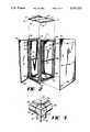
- FIG. 1is a perspective view of an EMI/RFI shielded cabinet.
- FIG. 2is an exploded view of an EMI/RFI shielded cabinet, shown with the right panel and and top exploded and the door open;
- FIG. 3is a close up view of the corner construction of an EMI/RFI shielded cabinet, showing the relationship between the corner and the top of the cabinet;
- FIG. 4is an exploded view of the corner assembly
- FIG. 5is a perspective view of an EMI/RFI shielding gasket
- FIG. 6is a partial horizontal cross sectional view taken along line 6--6 of FIG. 1, showing an EMI/RFI shielding gasket installed in a cabinet and the relation between the gasket and a door and a side panel of the cabinet.
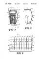
- FIG. 7is a cross-sectional view of the EMI/RFI shielding gasket of FIG. 5 taken along line 7--7.
- FIG. 8is an end view of the conductor showing the bends which are made to form the conductor.
- FIG. 9is a front plan view of a preferred embodiment of a metal blank from which is formed a conductor utilized in the EMI/RFI shielding gasket of FIG. 5.
- FIG. 10is a fragmentary close-up view of the EMI/RFI gasket of FIG. 5 installed on the cabinet of FIG. 1.
- FIG. 11is a cross-sectional view taken along line 11--11 of FIG. 10, showing the relation between a pair of EMI/RFI shielding gaskets installed in a cabinet.
- FIGS. 1 and 2show an EMI/RFI shielding cabinet 10 on which the gasket of the present invention is preferably mounted.
- the cabinet 10has a frame 11, side panels 12, door panels 13, a top panel 14, and a bottom panel 15.
- Each of the panels 12-15are rectangular in shape and have a lip 16 formed on their edges.
- the top panel 14has a rectangular cutout 17 at each corner.
- the side panels 12 and top panel 14are mounted to the frame 11 as will be described later.
- Doors 13are mounted to the frame 11 with hinges 20.
- the bottom panel 15is bolted directly to the frame 11.
- a jointis defined at the intersection of each of the panels 12-15 and the frame 11.
- Brackets 21, having holes 22, and supports 23are mounted to the frame 11 and enable trays or drawers to be installed in the cabinet.
- the frame 11 of the cabinet 10is constructed from a plurality of corner members 25, horizontal frame members 26 and vertical frame members 27. Extending from each corner member 25 are brackets 28. Each horizontal frame member 26 and vertical frame member 27 is slidably positioned over a bracket 28 and abuts the corner member 25. The horizontal frame members 26 and vertical frame members 27 may be welded or otherwise bonded to each other along their interior edges to inhibit the passage of RF waves, moisture and debris.
- a plurality of nipples 30are defined on one or more interior surfaces of each of the horizontal frame members 26 and vertical frame members 27. The nipples 30 may be forcibly impressed into the brackets 28 to align the horizontal frame members 26 and the vertical frame member 27 with the corner member 25.
- Each horizontal frame member 26 and vertical frame member 27also has a rim or flange 31 defined thereon, onto which a gasket may be mounted. Ridges 32 are defined in each horizontal frame member 26 and vertical frame member 27 onto which supports 23 are mounted. A recess 33 is defined on the front surface of one side of the corner member 25 and one of the horizontal frame members 26 for placement of an emblem or sign.
- a projection 34extends upwardly from the corner member 25.
- the top panel 14is the same height as the projection 34 and is positioned flush with and abutting the projection 34 with the projection being received within a cutout 17 in the top panel 14.
- Extending upwardly from the inner edge of each horizontal frame member 26is a flange 35.
- each flange 35is interior to the lips 16 of the top panel 14.
- the lips 16 of the top panel 14are preferably inclined outwardly from parallel so as to provide a natural drain path from the top of the cabinet.
- This lip and flange arrangementprovides a barrier to the passage of RF waves, moisture and debris and promotes the drainage of moisture from the top of the cabinet.
- a gasketmay be mounted on each flange 35 to provide enhanced EMI/RFI, moisture and debris protection.
- each projection 34has a threaded bore 36 formed therein.
- An eyelet, hook, or other device useful in transporting the cabinetmay be threaded into the bore 36.
- wheels or castersmay also be threaded into the bore of the bottom corner members to enable the cabinet 10 to be rolled from place to place.
- FIG. 5shows a shielding device 39 including a gasket 40 having a tubular head 41.
- An interconnected pair of legs 42L and 42R having mutually facing surfaces 43extend downwardly from the lower portion of the head 41.
- a U-shaped reinforcing lug 44is embedded within the legs 42L and 42R and maintains the legs in a mutually opposed relationship.
- the lug 44is flexible, preferably being made from steel wire, to allow the gasket 40 to conform to curved surfaces and corners.
- a pair of ears 45 and 45Aangle upwardly from the upper portion of the head 41.
- a plurality of barbs 46 on the leg member 42L and a barb 47 on the leg member 42Rangle upwardly and are spaced to frictionally engage flanges 31 or 35 to allow secure positioning of the shielding device 39 on a flange.
- the tubular head 41, legs 42L and 42R, ears 45 and 45A, and barbs 46 and 47are preferably made of rubber and coextruded with the lug 44.
- the shielding device 39 of the disclosed embodimentis manufactured from a commercially available gasket produced by Emka, model no. 1011-05.
- a conductor 48is positioned adjacent to the gasket 40 between points A and B, so that the conductor 48 covers the periphery of the gasket 40 from the ear 45, across the ear 45A, across the tubular head 41, down the outer surface of the leg 42L, and up an inner surface 43 to the tip of the barb 47. It will be understood that the ear 45A which is covered by the conductor 48 may be removed if desired.
- FIGS. 5, 7, 8, and 9there is shown a preferred construction of the conductor 48.
- the conductoris preferably formed from about a 0.004 inch thick hard temper beryllium copper blank 49, shown in FIG. 9, having a bright tin plating of a thickness of between about 0.0001 and 0.0003 inch.
- a plurality of gaps 53are formed on the blank 49 to delineate a plurality of individually movable fingers 54.
- This materialis commercially available in coils and may be configured to the specifications detailed below using conventional metal working equipment. Referring to FIGS.
- the conductor 48is preferably configured to have an elongate strip 50 which extends between the legs 42L and 42R, and an elongate strip 52 in the shape of an inwardly curled lip extending along the outer surface of the head 41 adjacent the ear 45.
- the plurality of individually movable fingers 54extend between the strips 50 and 52 to provide a unitary structure.
- the conductor 48may be formed by bending the blank 49 along bend lines 61, 63, 65, and 67.
- the strip 52also provides a smooth interface between the conductor 48 and the head 41 so that the conductor 48 does not cut into the gasket 39.
- An L-shaped extension 59is provided on the strip 50 to provide additional rigidity to the strip 50 and to provide an additional conductive surface area for contact with the flange 31 or 35.
- the gaps 53are provided between each of the fingers 54 to provide sufficient clearance for movement. Each gap is preferably of a dimension to block selected wavelengths of electromagnetic radiation such as radio frequency waves.
- each fingerhas a width of approximately 0.56 inch.
- Thisprovides a gasket capable of shielding equipment producing a wavelength of 1.75 angstroms, which is common in the electronics field.
- the fingersare preferably shaped utilizing gradual corners at the bend lines 61, 63, 65, and 67, such that each finger is divided into four sections 56, 58, 60 and 62. As shown in FIG.
- the sectionsare configured such that the angle F between sections 56 and 58 is about 105°; the angle G between sections 58 and 60 is about 140°; the angle H between sections 60 and 62 is about 90°; and the angle I between section 62 and the strip 50 is about 110°. It is also preferred that the lip 52 is about 0.178 inch in length, with an angle J between the lip 52 and section 56 of about 16°.
- the bend line 63 between sections 58 and 60defines a flex-point 64 on each finger. These flex points provide the fingers with a spring-like action for improved resiliency. For example, when the head 41 is compressed toward the legs 42L and 42R when a door is closed upon the shielding device, sections 58 and 60 move together so as to decrease the angle G between them.
- the sealing devicemay be of any size, the relative sizes are preferably made in accordance with the above example.
- the sealing deviceprovides a segmented conductive contacting surface having uniform resiliency and capable of withstanding repeated openings and closings of the cabinet 10 without losing alignment of the fingers 54. The alignment is maintained because the novel configuration of the conductor prevents the fingers from becoming permanently bent at various angles. Additionally, the bright, tin plating allows the uniform contact surfaces provided on the conductor to reflect light in a uniform and aesthetically pleasing manner.
- the shielding properties of the cabinet 10may be enhanced to provide increased protection from RF waves, moisture and debris.
- the gasket 40is mounted to a flange 35 or 31 by means of the legs 42L and 42R.
- the legs 42L and 42Rare placed over the flange and the barbs 46 and 47 frictionally engage the flange.
- the lug 44may be manually compressed inwardly toward the flange to increase the pressure exerted by legs 42L and 42R and barbs 46 and 47 on the flange 35 or 31.
- This mounting techniqueallows the shielding device to be securely but quickly and evenly installed or removed without necessitating the use of fasteners, adhesives or other securing devices and allows positioning of the sealing device to provide effective shielding, as explained below.
- the conductor 48extends between the legs 42L and 42R. Therefore, when the gasket 40 is mounted on a flange 35 or 31, section 50 and extension 59 of the conductor are in direct contact with the flange. Also, when the door panel 13 is closed and the side panels 12 are mounted, portions of the interior surfaces of the panels are in direct contact with sections 56, 58, and 60 of the conductor 48. This provides a barrier to the passage of RF waves.
- the ear 45is also in direct contact with the interior surfaces of the panels 12-15. Moisture and debris are restrained from passing through each joint by the tubular head 41 and ear 45. Moisture and debris allowed to invade the cabinet could damage electrical equipment. Furthermore, the ear 45 protects the conductor 48 from exposure to moisture and debris, thus protecting against degradation of the electrical connection between the doors or side panels and the frame members. Moisture and debris collected on the conductor would degrade the conductor.
- a shielding device 39is shown mounted on a cabinet 10.
- Each side panel 12has a hole defined therein through which a bolt 50 is inserted.
- a recess 51is preferably provided on each panel 12 to allow a counter-sunk appearance.
- a latch arm 54is attached to the inserted bolt 50.
- a mounting plate 55is mounted to each vertical frame member 27 by a screw 56, with a portion thereof extending outwardly parallel to the side panel 12.
- the bolt 50is rotated to position the latch arm 54 against the inner facing surface of the mounting plate 55.
- a slot or other configurationmay be provided on each bolt 50 to facilitate rotation.
- the door panel 13is mounted using the hinge 20 screwed or bolted to the frame member 27 and positioned in a manner described below.
- the door panel 13is shown in solid lines in its closed position in contact with one of the shielding devices 39 mounted on one of the flanges 31 and in phantom lines in various stages of opening and closing.
- a pair of sealing devices 39are shown mounted on flanges 31 of the cabinet 10 to provide EMI/RFI shielding. Because the door panel 13 is generally opened and closed many more times that the other panels, it is critical that the door panel and the sealing device cooperate to provide protection which withstands repeated openings and closings of the door panel. As is shown, the door panel 13 includes a reinforcing member or extrusion 70 which extends vertically along the interior surface of the door panel and is spaced inwardly from the hinge 20. This arrangement results in contact between an inner edge 71 of the extrusion 70 and flexpoints 64 and sections 58 and 60 of the conductor 48 when the door panel is closed.
- an interior surface 73 of the door panelcontacts sections 56 of the conductor and the ear 45 of the gasket 40.
- the hingeis preferably located near an edge of the door panel so that the mounted sealing device is positioned between the hinge and the extrusion 70 when the door panel is closed.
- FIGS. 3, 10, and 11it can be seen that the relative positions of the flanges are important to allow positioning of lengths of the sealing device to eliminate gaps between lengths which would allow electromagnetic waves, moisture, and debris to pass through the panel openings.
- the flangesare positioned such that portions of the conductors 48A and 48B on each of the tubular heads 41A and 41B of adjacent lengths of sealing devices 39A and 39B are in direct contact with one another to provide a continuous conductive interface.
- each flange 31A and 31Bmay be offsetting from the edge of each horizontal and vertical frame member by a distance Q, which is approximately equal to the width of the leg 42L. In the preferred embodiment, distance Q is about 0.09 inch.
- the novel positioning of the flanges 31A and 31Ballows the sealing device 39A to abut the sealing device 39B adjacent thereto. This places a cross-sectional edge of sections 58A and 60A and flexpoint 64A of the conductor 48A in contact with an edge of the conductor 48B.
- Each conductor 48A and 48Bis positioned on its respective sealing device 39A or 39B in the manner previously explained for sealing device 39 and conductor 48.
- a filler materialsuch as silicone may be provided along the outer edge of the interface in a manner which does not interfere with the conductive contact between the sealing devices.
Landscapes
- Engineering & Computer Science (AREA)
- Power Engineering (AREA)
- Microelectronics & Electronic Packaging (AREA)
- Shielding Devices Or Components To Electric Or Magnetic Fields (AREA)
Abstract
Description
Claims (25)
Priority Applications (1)
| Application Number | Priority Date | Filing Date | Title |
|---|---|---|---|
| US07/662,296US5147121A (en) | 1989-11-13 | 1991-02-28 | Gasket for providing EMI/RFI shielding |
Applications Claiming Priority (2)
| Application Number | Priority Date | Filing Date | Title |
|---|---|---|---|
| US07/434,323US5020866A (en) | 1989-11-13 | 1989-11-13 | Enclosure for housing electronic components |
| US07/662,296US5147121A (en) | 1989-11-13 | 1991-02-28 | Gasket for providing EMI/RFI shielding |
Related Parent Applications (1)
| Application Number | Title | Priority Date | Filing Date |
|---|---|---|---|
| US07/434,323Continuation-In-PartUS5020866A (en) | 1989-11-13 | 1989-11-13 | Enclosure for housing electronic components |
Publications (1)
| Publication Number | Publication Date |
|---|---|
| US5147121Atrue US5147121A (en) | 1992-09-15 |
Family
ID=27030145
Family Applications (1)
| Application Number | Title | Priority Date | Filing Date |
|---|---|---|---|
| US07/662,296Expired - Fee RelatedUS5147121A (en) | 1989-11-13 | 1991-02-28 | Gasket for providing EMI/RFI shielding |
Country Status (1)
| Country | Link |
|---|---|
| US (1) | US5147121A (en) |
Cited By (33)
| Publication number | Priority date | Publication date | Assignee | Title |
|---|---|---|---|---|
| US5536079A (en)* | 1991-05-22 | 1996-07-16 | Asea Brown Boveri Ltd. | Cabinet |
| US5788538A (en)* | 1996-07-31 | 1998-08-04 | Berg Technology, Inc. | Shield for modular jack |
| DE19711175A1 (en)* | 1997-03-18 | 1998-09-24 | Happich Fahrzeug & Ind Teile | Profiled sealing strip for e.g. electrical equipment |
| US5902026A (en)* | 1997-02-03 | 1999-05-11 | Hoffman Enclosures, Inc. | Vented cabinet door with full length window |
| US6121545A (en)* | 1997-07-11 | 2000-09-19 | Parker-Hannifin Corporation | Low closure force EMI shielding spacer gasket |
| US6157546A (en)* | 1999-03-26 | 2000-12-05 | Ericsson Inc. | Shielding apparatus for electronic devices |
| US6348654B1 (en) | 2000-10-12 | 2002-02-19 | Parker-Hannifin Corporation | Compound waveform gasket for low closure force EMI shielding applications |
| US20020140325A1 (en)* | 2001-04-02 | 2002-10-03 | Webster James W. | Modular enclosure system for electronic equipment |
| US6521828B2 (en) | 2001-05-11 | 2003-02-18 | Parker-Hannifin Corporation | Notched gasket for low closure force EMI shielding applications |
| US20030091777A1 (en)* | 2001-08-14 | 2003-05-15 | Peter Jones | Clean release tape for EMI shielding |
| US20030209355A1 (en)* | 2001-08-21 | 2003-11-13 | Dell Products L.P. | Perforated EMI gasket |
| US6763576B2 (en) | 2001-05-10 | 2004-07-20 | Parker-Hannifin Corporation | Manufacture of electronics enclosure having a metallized shielding layer |
| US6784363B2 (en) | 2001-10-02 | 2004-08-31 | Parker-Hannifin Corporation | EMI shielding gasket construction |
| US6809254B2 (en) | 2001-07-20 | 2004-10-26 | Parker-Hannifin Corporation | Electronics enclosure having an interior EMI shielding and cosmetic coating |
| USD630173S1 (en) | 2009-04-20 | 2011-01-04 | Chatsworth Products, Inc. | Cover for electronic equipment cabinet |
| USD632660S1 (en) | 2009-04-20 | 2011-02-15 | Chatsworth Products, Inc. | Cover for electronic equipment cabinet |
| US20110050052A1 (en)* | 2009-09-01 | 2011-03-03 | Emerson Network Power, Energy Systems, North America, Inc. | Telecommunications Enclosures |
| US20120090886A1 (en)* | 2010-10-14 | 2012-04-19 | Innochips Technology Co., Ltd. | Emi shielding gasket |
| US20120090885A1 (en)* | 2010-10-14 | 2012-04-19 | Innochips Technology Co., Ltd. | Emi shielding gasket |
| USD684128S1 (en) | 2012-02-10 | 2013-06-11 | Chatsworth Products, Inc. | Containment aisle door |
| US9313927B2 (en) | 2010-11-08 | 2016-04-12 | Chatsworth Products, Inc. | Header panel assembly for preventing air circulation above electronic equipment enclosure |
| US9572286B2 (en) | 2013-01-11 | 2017-02-14 | Chatsworth Products, Inc. | Modular thermal isolation barrier for data processing equipment structure |
| US9585266B2 (en) | 2010-11-08 | 2017-02-28 | Chatsworth Products, Inc. | Header panel assembly for preventing air circulation above electronic equipment enclosure |
| US9655259B2 (en) | 2011-12-09 | 2017-05-16 | Chatsworth Products, Inc. | Data processing equipment structure |
| US9955616B2 (en) | 2010-11-08 | 2018-04-24 | Chatsworth Products, Inc. | Header panel assembly for preventing air circulation above electronic equipment enclosure |
| WO2020197618A1 (en)* | 2019-03-26 | 2020-10-01 | Raytheon Company | Multidirectional enclosure compression locking mechanism |
| US11191196B2 (en)* | 2019-06-12 | 2021-11-30 | Joinset Co., Ltd. | Solderable electric conductive gasket |
| EP3545247B1 (en)* | 2016-11-22 | 2022-04-13 | REHAU Industries SE & Co. KG | Profile arrangement, in particular for a refrigerator and/or freezer |
| US11622458B1 (en) | 2020-12-15 | 2023-04-04 | Chatsworth Products, Inc. | Brush port assembly and method for installing same |
| US11678456B1 (en) | 2020-12-15 | 2023-06-13 | Chatsworth Products, Inc. | Slidable mounting hardware for electronic equipment enclosure and method for installing same |
| US11818862B1 (en) | 2020-12-15 | 2023-11-14 | Chatsworth Products, Inc. | Frame structure for electronic equipment enclosure |
| US11920392B1 (en) | 2021-02-02 | 2024-03-05 | Chatsworth Products, Inc. | Electrical bonding door hinges |
| US12048108B1 (en) | 2020-12-15 | 2024-07-23 | Chatsworth Products, Inc. | Caster attachment system using mating features |
Citations (10)
| Publication number | Priority date | Publication date | Assignee | Title |
|---|---|---|---|---|
| US3026367A (en)* | 1959-05-08 | 1962-03-20 | Tech Wire Prod Inc | Shielding and mounting strip |
| US3583930A (en)* | 1968-04-16 | 1971-06-08 | Chomerics Inc | Plastics made conductive with coarse metal fillers |
| US3812316A (en)* | 1973-03-28 | 1974-05-21 | Gen Electric | Door seal gasket for combined microwave and self-cleaning oven |
| US4391478A (en)* | 1980-05-14 | 1983-07-05 | Sybron Corporation | Drawer seal |
| US4572921A (en)* | 1984-07-30 | 1986-02-25 | Instrument Specialties Co., Inc. | Electromagnetic shielding device |
| US4652695A (en)* | 1983-06-20 | 1987-03-24 | Pawling Corporation | Mesh-covered core strip for high frequency RFI/EMI radiation shielding |
| US4659869A (en)* | 1983-06-20 | 1987-04-21 | Pawling Rubber Corporation | Clip-on strip for RFT/EMI shielding |
| US4705916A (en)* | 1986-02-14 | 1987-11-10 | Northern Telecom Limited | EMI gasket retaining mechanism for electronic equipment |
| US4720606A (en)* | 1985-06-28 | 1988-01-19 | Jakob Senn | Seal in housing means containing electrical apparatuses |
| US4864070A (en)* | 1988-03-28 | 1989-09-05 | Amoco Corporation | Process for the separation of ortho chlorinated aromatic isomers by selective adsorption |
- 1991
- 1991-02-28USUS07/662,296patent/US5147121A/ennot_activeExpired - Fee Related
Patent Citations (10)
| Publication number | Priority date | Publication date | Assignee | Title |
|---|---|---|---|---|
| US3026367A (en)* | 1959-05-08 | 1962-03-20 | Tech Wire Prod Inc | Shielding and mounting strip |
| US3583930A (en)* | 1968-04-16 | 1971-06-08 | Chomerics Inc | Plastics made conductive with coarse metal fillers |
| US3812316A (en)* | 1973-03-28 | 1974-05-21 | Gen Electric | Door seal gasket for combined microwave and self-cleaning oven |
| US4391478A (en)* | 1980-05-14 | 1983-07-05 | Sybron Corporation | Drawer seal |
| US4652695A (en)* | 1983-06-20 | 1987-03-24 | Pawling Corporation | Mesh-covered core strip for high frequency RFI/EMI radiation shielding |
| US4659869A (en)* | 1983-06-20 | 1987-04-21 | Pawling Rubber Corporation | Clip-on strip for RFT/EMI shielding |
| US4572921A (en)* | 1984-07-30 | 1986-02-25 | Instrument Specialties Co., Inc. | Electromagnetic shielding device |
| US4720606A (en)* | 1985-06-28 | 1988-01-19 | Jakob Senn | Seal in housing means containing electrical apparatuses |
| US4705916A (en)* | 1986-02-14 | 1987-11-10 | Northern Telecom Limited | EMI gasket retaining mechanism for electronic equipment |
| US4864070A (en)* | 1988-03-28 | 1989-09-05 | Amoco Corporation | Process for the separation of ortho chlorinated aromatic isomers by selective adsorption |
Non-Patent Citations (5)
| Title |
|---|
| Co extruded Conductive Elastomer Strips undated.* |
| Co-extruded Conductive Elastomer Strips undated. |
| Optima R Series Vertical Cabinets EMI/RFI Shielded Features (p. 4) Gichner Optima Enclosures Undated.* |
| Optima Vertical Cabinets EMI/RFI Shielded Features (p. 4) Gichner Optima Enclosures undated.* |
| Schlegal EMI Shielding Gaskets Schlegal Corporation Undated.* |
Cited By (66)
| Publication number | Priority date | Publication date | Assignee | Title |
|---|---|---|---|---|
| US5536079A (en)* | 1991-05-22 | 1996-07-16 | Asea Brown Boveri Ltd. | Cabinet |
| US5788538A (en)* | 1996-07-31 | 1998-08-04 | Berg Technology, Inc. | Shield for modular jack |
| US5957726A (en)* | 1996-07-31 | 1999-09-28 | Berg Technology, Inc. | Shield for modular jack |
| US6379185B2 (en) | 1996-07-31 | 2002-04-30 | Fci Americas Technology, Inc. | Shield for modular jack |
| US5902026A (en)* | 1997-02-03 | 1999-05-11 | Hoffman Enclosures, Inc. | Vented cabinet door with full length window |
| EP0856633A3 (en)* | 1997-02-03 | 2000-01-05 | Federal-Hoffman, Inc. | Vented cabinet door with full length window |
| DE19711175A1 (en)* | 1997-03-18 | 1998-09-24 | Happich Fahrzeug & Ind Teile | Profiled sealing strip for e.g. electrical equipment |
| US6121545A (en)* | 1997-07-11 | 2000-09-19 | Parker-Hannifin Corporation | Low closure force EMI shielding spacer gasket |
| US6392900B1 (en) | 1999-03-26 | 2002-05-21 | Ericsson Inc. | Shielding apparatus for electronic devices |
| US6157546A (en)* | 1999-03-26 | 2000-12-05 | Ericsson Inc. | Shielding apparatus for electronic devices |
| US6348654B1 (en) | 2000-10-12 | 2002-02-19 | Parker-Hannifin Corporation | Compound waveform gasket for low closure force EMI shielding applications |
| US20020140325A1 (en)* | 2001-04-02 | 2002-10-03 | Webster James W. | Modular enclosure system for electronic equipment |
| US6945616B2 (en)* | 2001-04-02 | 2005-09-20 | Emerson Network Power, Energy Systems, North America, Inc. | Modular enclosure system for electronic equipment |
| US6763576B2 (en) | 2001-05-10 | 2004-07-20 | Parker-Hannifin Corporation | Manufacture of electronics enclosure having a metallized shielding layer |
| US6521828B2 (en) | 2001-05-11 | 2003-02-18 | Parker-Hannifin Corporation | Notched gasket for low closure force EMI shielding applications |
| US6809254B2 (en) | 2001-07-20 | 2004-10-26 | Parker-Hannifin Corporation | Electronics enclosure having an interior EMI shielding and cosmetic coating |
| US20030091777A1 (en)* | 2001-08-14 | 2003-05-15 | Peter Jones | Clean release tape for EMI shielding |
| US6858794B2 (en)* | 2001-08-21 | 2005-02-22 | Dell Products L.P. | Perforated EMI gasket |
| US20030209355A1 (en)* | 2001-08-21 | 2003-11-13 | Dell Products L.P. | Perforated EMI gasket |
| US6784363B2 (en) | 2001-10-02 | 2004-08-31 | Parker-Hannifin Corporation | EMI shielding gasket construction |
| USD630173S1 (en) | 2009-04-20 | 2011-01-04 | Chatsworth Products, Inc. | Cover for electronic equipment cabinet |
| USD632660S1 (en) | 2009-04-20 | 2011-02-15 | Chatsworth Products, Inc. | Cover for electronic equipment cabinet |
| US8403431B2 (en)* | 2009-09-01 | 2013-03-26 | Emerson Network Power, Energy Systems, North America, Inc. | Telecommunications enclosures |
| US20110050052A1 (en)* | 2009-09-01 | 2011-03-03 | Emerson Network Power, Energy Systems, North America, Inc. | Telecommunications Enclosures |
| US20120090886A1 (en)* | 2010-10-14 | 2012-04-19 | Innochips Technology Co., Ltd. | Emi shielding gasket |
| US8907229B2 (en)* | 2010-10-14 | 2014-12-09 | Innochips Technology Co., Ltd. | EMI shielding gasket |
| US20120090885A1 (en)* | 2010-10-14 | 2012-04-19 | Innochips Technology Co., Ltd. | Emi shielding gasket |
| CN102458090A (en)* | 2010-10-14 | 2012-05-16 | 英诺晶片科技股份有限公司 | Electromagnetic interference shielding gasket |
| US8822842B2 (en)* | 2010-10-14 | 2014-09-02 | Innochips Technology Co., Ltd. | EMI shielding gasket |
| US11889633B2 (en) | 2010-11-08 | 2024-01-30 | Chatsworth Products, Inc. | Header panel assembly for preventing air circulation above electronic equipment enclosure |
| US9313927B2 (en) | 2010-11-08 | 2016-04-12 | Chatsworth Products, Inc. | Header panel assembly for preventing air circulation above electronic equipment enclosure |
| US12349320B2 (en) | 2010-11-08 | 2025-07-01 | Chatsworth Products, Inc. | Header panel assembly for preventing air circulation above electronic equipment enclosure |
| US9585266B2 (en) | 2010-11-08 | 2017-02-28 | Chatsworth Products, Inc. | Header panel assembly for preventing air circulation above electronic equipment enclosure |
| US10568246B2 (en) | 2010-11-08 | 2020-02-18 | Chatsworth Products, Inc. | Header panel assembly for preventing air circulation above electronic equipment enclosure |
| US11166395B2 (en) | 2010-11-08 | 2021-11-02 | Chatsworth Products, Inc. | Header panel assembly for preventing air circulation above electronic equipment enclosure |
| US9955616B2 (en) | 2010-11-08 | 2018-04-24 | Chatsworth Products, Inc. | Header panel assembly for preventing air circulation above electronic equipment enclosure |
| US10306812B2 (en) | 2010-11-08 | 2019-05-28 | Chatsworth Products, Inc. | Header panel assembly for preventing air circulation above electronic equipment enclosure |
| US10932400B2 (en) | 2010-11-08 | 2021-02-23 | Chatsworth Products, Inc. | Header panel assembly for preventing air circulation above electronic equipment enclosure |
| US9655259B2 (en) | 2011-12-09 | 2017-05-16 | Chatsworth Products, Inc. | Data processing equipment structure |
| US10709039B2 (en) | 2011-12-09 | 2020-07-07 | Chatsworth Products, Inc. | Data processing equipment structure |
| USD684128S1 (en) | 2012-02-10 | 2013-06-11 | Chatsworth Products, Inc. | Containment aisle door |
| US10375861B2 (en) | 2013-01-11 | 2019-08-06 | Chatsworth Products, Inc. | Modular thermal isolation barrier for data processing equipment structure |
| US9572286B2 (en) | 2013-01-11 | 2017-02-14 | Chatsworth Products, Inc. | Modular thermal isolation barrier for data processing equipment structure |
| US9795060B2 (en) | 2013-01-11 | 2017-10-17 | Chatsworth Products, Inc. | Modular thermal isolation barrier for data processing equipment structure |
| US20220061188A1 (en)* | 2013-01-11 | 2022-02-24 | Chatsworth Products, Inc. | Modular thermal isolation barrier for data processing equipment structure |
| US12063758B2 (en) | 2013-01-11 | 2024-08-13 | Chatsworth Products, Inc. | Modular thermal isolation barrier for data processing equipment structure |
| US11647610B2 (en)* | 2013-01-11 | 2023-05-09 | Chatsworth Products, Inc. | Modular thermal isolation barrier for data processing equipment structure |
| US10595442B2 (en) | 2013-01-11 | 2020-03-17 | Chatsworth Products, Inc. | Data processing equipment structure |
| EP3545247B1 (en)* | 2016-11-22 | 2022-04-13 | REHAU Industries SE & Co. KG | Profile arrangement, in particular for a refrigerator and/or freezer |
| US11447982B2 (en) | 2019-03-26 | 2022-09-20 | Raytheon Company | Multidirectional enclosure compression locking mechanism |
| WO2020197618A1 (en)* | 2019-03-26 | 2020-10-01 | Raytheon Company | Multidirectional enclosure compression locking mechanism |
| US11191196B2 (en)* | 2019-06-12 | 2021-11-30 | Joinset Co., Ltd. | Solderable electric conductive gasket |
| US11678456B1 (en) | 2020-12-15 | 2023-06-13 | Chatsworth Products, Inc. | Slidable mounting hardware for electronic equipment enclosure and method for installing same |
| US12048108B1 (en) | 2020-12-15 | 2024-07-23 | Chatsworth Products, Inc. | Caster attachment system using mating features |
| US11818861B1 (en) | 2020-12-15 | 2023-11-14 | Chatsworth Products, Inc. | Frame structure for electronic equipment enclosure |
| US11818860B1 (en) | 2020-12-15 | 2023-11-14 | Chatsworth Products, Inc. | Frame structure for electronic equipment enclosure |
| US11678458B1 (en) | 2020-12-15 | 2023-06-13 | Chatsworth Products, Inc. | Slidable mounting hardware for electronic equipment enclosure and method for installing same |
| US11903156B1 (en) | 2020-12-15 | 2024-02-13 | Chatsworth Products, Inc. | Brush port assembly and method for installing same |
| US11622458B1 (en) | 2020-12-15 | 2023-04-04 | Chatsworth Products, Inc. | Brush port assembly and method for installing same |
| US11818862B1 (en) | 2020-12-15 | 2023-11-14 | Chatsworth Products, Inc. | Frame structure for electronic equipment enclosure |
| US11627677B1 (en) | 2020-12-15 | 2023-04-11 | Chatsworth Products, Inc. | Brush port assembly and method for installing same |
| US12089363B1 (en) | 2020-12-15 | 2024-09-10 | Chatsworth Products, Inc. | Slidable mounting hardware for electronic equipment enclosure |
| US12160974B1 (en) | 2020-12-15 | 2024-12-03 | Chatsworth Products, Inc. | Frame structure for electronic equipment enclosure |
| US12342486B1 (en) | 2020-12-15 | 2025-06-24 | Chatsworth Products, Inc. | Port barrier assembly and method for installing same |
| US11920392B1 (en) | 2021-02-02 | 2024-03-05 | Chatsworth Products, Inc. | Electrical bonding door hinges |
| US12428888B1 (en) | 2021-02-02 | 2025-09-30 | Chatsworth Products, Inc. | Electrical bonding door hinges |
Similar Documents
| Publication | Publication Date | Title |
|---|---|---|
| US5147121A (en) | Gasket for providing EMI/RFI shielding | |
| US5194691A (en) | Gasket and cabinet for providing EMI/RFI shielding | |
| US5020866A (en) | Enclosure for housing electronic components | |
| USRE34393E (en) | Enclosure for housing electronic components | |
| US4820885A (en) | Magnetic gasket for shielding against electromagnetic radiation | |
| US5600091A (en) | HF shielded electrical enclosures | |
| US4659869A (en) | Clip-on strip for RFT/EMI shielding | |
| CA2205667C (en) | Door assembly for shielded room | |
| US6142595A (en) | Container having a self-aligning and sealable closure | |
| US4857668A (en) | Multi-function gasket | |
| US4786758A (en) | Door shield for shielded enclosure | |
| US4705916A (en) | EMI gasket retaining mechanism for electronic equipment | |
| CA2314202C (en) | Emi shielded telecommunications enclosure | |
| US6073896A (en) | Gasket arrangement having retention clip track and method of making a gasket arrangement and method for securing a gasket to a wall | |
| US5402323A (en) | Equipment cabinet having spring-elastic seals | |
| JPH11514198A (en) | Switchboard cabinet with frame structure | |
| US4761516A (en) | Electromagnetic interference shielding device | |
| US6173970B1 (en) | Gasket and method of making a gasket | |
| KR910000599B1 (en) | Sealing device for metal cabinets shielding electromagnetic fields | |
| US6162989A (en) | Cable entry shield (EMI-RFI) for electronic units | |
| US6314683B1 (en) | Seal | |
| WO1994030035A1 (en) | Insulator means for suppressing interference radiation in an electric field | |
| GB2340673A (en) | Sealing of motor terminal box | |
| US5145087A (en) | Closure hinge mechanism | |
| EP0463704A1 (en) | Protection system for use in movable panels mounted in a frame |
Legal Events
| Date | Code | Title | Description |
|---|---|---|---|
| AS | Assignment | Owner name:GICHNER SYSTEMS GROUP, INC., EAST LOCUST STREET, D Free format text:ASSIGNMENT OF ASSIGNORS INTEREST.;ASSIGNOR:MC IIWRAITH, GEORGE;REEL/FRAME:005679/0936 Effective date:19910401 | |
| FPAY | Fee payment | Year of fee payment:4 | |
| AS | Assignment | Owner name:PAUDENTIAL INSURANCE COMPANY OF AMERICA., THE, NEW Free format text:SECURITY INTEREST;ASSIGNOR:GICHNER SYSTEMS GROUP. INC.;REEL/FRAME:007773/0742 Effective date:19960123 | |
| REMI | Maintenance fee reminder mailed | ||
| LAPS | Lapse for failure to pay maintenance fees | ||
| FP | Lapsed due to failure to pay maintenance fee | Effective date:20000915 | |
| AS | Assignment | Owner name:NATIONAL PENN BANK, PENNSYLVANIA Free format text:SECURITY AGREEMENT;ASSIGNOR:GICHNER SYSTEMS GROUP, INC.;REEL/FRAME:019730/0916 Effective date:20070822 | |
| AS | Assignment | Owner name:GICHNER ACQUISITION, INC., PENNSYLVANIA Free format text:ASSIGNMENT OF ASSIGNORS INTEREST;ASSIGNOR:GICHNER SYSTEMS GROUP, LLC;REEL/FRAME:019767/0029 Effective date:20070822 Owner name:GICHNER ACQUISITION, INC.,PENNSYLVANIA Free format text:ASSIGNMENT OF ASSIGNORS INTEREST;ASSIGNOR:GICHNER SYSTEMS GROUP, LLC;REEL/FRAME:019767/0029 Effective date:20070822 | |
| AS | Assignment | Owner name:ARGOSY INVESTMENT PARTNERS III, L.P., PENNSYLVANIA Free format text:SECURITY AGREEMENT;ASSIGNORS:GICHNER ACQUISITION, INC.;GICHNER SYSTEMS GROUP, INC.;REEL/FRAME:020041/0516 Effective date:20070822 Owner name:ARGOSY INVESTMENT PARTNERS III, L.P.,PENNSYLVANIA Free format text:SECURITY AGREEMENT;ASSIGNORS:GICHNER ACQUISITION, INC.;GICHNER SYSTEMS GROUP, INC.;REEL/FRAME:020041/0516 Effective date:20070822 | |
| AS | Assignment | Owner name:GICHNER SYSTEMS INTERNATIONAL, INC.,PENNSYLVANIA Free format text:RELEASE BY SECURED PARTY;ASSIGNOR:NATIONAL PENN BANK;REEL/FRAME:024458/0621 Effective date:20100519 | |
| STCH | Information on status: patent discontinuation | Free format text:PATENT EXPIRED DUE TO NONPAYMENT OF MAINTENANCE FEES UNDER 37 CFR 1.362 |