US5146989A - Apparatus for recovering a wellhead - Google Patents
Apparatus for recovering a wellheadDownload PDFInfo
- Publication number
- US5146989A US5146989AUS07/671,812US67181291AUS5146989AUS 5146989 AUS5146989 AUS 5146989AUS 67181291 AUS67181291 AUS 67181291AUS 5146989 AUS5146989 AUS 5146989A
- Authority
- US
- United States
- Prior art keywords
- wellhead
- shaft
- housing
- latch device
- engagement
- Prior art date
- Legal status (The legal status is an assumption and is not a legal conclusion. Google has not performed a legal analysis and makes no representation as to the accuracy of the status listed.)
- Expired - Lifetime
Links
- 230000007246mechanismEffects0.000claimsabstractdescription8
- 230000009471actionEffects0.000claimsdescription4
- 230000001681protective effectEffects0.000description4
- 229910000906BronzeInorganic materials0.000description3
- 239000010974bronzeSubstances0.000description3
- KUNSUQLRTQLHQQ-UHFFFAOYSA-Ncopper tinChemical compound[Cu].[Sn]KUNSUQLRTQLHQQ-UHFFFAOYSA-N0.000description3
- 230000006835compressionEffects0.000description2
- 238000007906compressionMethods0.000description2
- 125000006850spacer groupChemical group0.000description2
- 230000008901benefitEffects0.000description1
- 238000010586diagramMethods0.000description1
- 230000004048modificationEffects0.000description1
- 238000012986modificationMethods0.000description1
- 238000011084recoveryMethods0.000description1
- 239000003381stabilizerSubstances0.000description1
Images


Classifications
- E—FIXED CONSTRUCTIONS
- E21—EARTH OR ROCK DRILLING; MINING
- E21B—EARTH OR ROCK DRILLING; OBTAINING OIL, GAS, WATER, SOLUBLE OR MELTABLE MATERIALS OR A SLURRY OF MINERALS FROM WELLS
- E21B19/00—Handling rods, casings, tubes or the like outside the borehole, e.g. in the derrick; Apparatus for feeding the rods or cables
- E21B19/002—Handling rods, casings, tubes or the like outside the borehole, e.g. in the derrick; Apparatus for feeding the rods or cables specially adapted for underwater drilling
- E—FIXED CONSTRUCTIONS
- E21—EARTH OR ROCK DRILLING; MINING
- E21B—EARTH OR ROCK DRILLING; OBTAINING OIL, GAS, WATER, SOLUBLE OR MELTABLE MATERIALS OR A SLURRY OF MINERALS FROM WELLS
- E21B29/00—Cutting or destroying pipes, packers, plugs or wire lines, located in boreholes or wells, e.g. cutting of damaged pipes, of windows; Deforming of pipes in boreholes or wells; Reconditioning of well casings while in the ground
- E21B29/12—Cutting or destroying pipes, packers, plugs or wire lines, located in boreholes or wells, e.g. cutting of damaged pipes, of windows; Deforming of pipes in boreholes or wells; Reconditioning of well casings while in the ground specially adapted for underwater installations
- E—FIXED CONSTRUCTIONS
- E21—EARTH OR ROCK DRILLING; MINING
- E21B—EARTH OR ROCK DRILLING; OBTAINING OIL, GAS, WATER, SOLUBLE OR MELTABLE MATERIALS OR A SLURRY OF MINERALS FROM WELLS
- E21B31/00—Fishing for or freeing objects in boreholes or wells
- E21B31/12—Grappling tools, e.g. tongs or grabs
- E21B31/16—Grappling tools, e.g. tongs or grabs combined with cutting or destroying means
- E—FIXED CONSTRUCTIONS
- E21—EARTH OR ROCK DRILLING; MINING
- E21B—EARTH OR ROCK DRILLING; OBTAINING OIL, GAS, WATER, SOLUBLE OR MELTABLE MATERIALS OR A SLURRY OF MINERALS FROM WELLS
- E21B31/00—Fishing for or freeing objects in boreholes or wells
- E21B31/12—Grappling tools, e.g. tongs or grabs
- E21B31/18—Grappling tools, e.g. tongs or grabs gripping externally, e.g. overshot
- E—FIXED CONSTRUCTIONS
- E21—EARTH OR ROCK DRILLING; MINING
- E21B—EARTH OR ROCK DRILLING; OBTAINING OIL, GAS, WATER, SOLUBLE OR MELTABLE MATERIALS OR A SLURRY OF MINERALS FROM WELLS
- E21B33/00—Sealing or packing boreholes or wells
- E21B33/02—Surface sealing or packing
- E21B33/03—Well heads; Setting-up thereof
- E21B33/035—Well heads; Setting-up thereof specially adapted for underwater installations
Definitions
- the inventionrelates to apparatus for recovering a wellhead.
- apparatus for recovering wellheadshas been designed to be inserted in&o the wellhead and casing and to lock on to internal threads on the inside of the wellhead. After the casing has been cut by a cutting mechanism located below the apparatus, the apparatus is used to retrieve the wellhead by pulling on the wellhead where the apparatus engages the wellhead internally.
- apparatus for recovering a wellheadcomprises a housing; a latch device; and a latch device actuator, the apparatus being such that when a force is applied to the apparatus to separate the apparatus from the wellhead the actuator causes the latch device to engage an external profile of the wellhead so that the apparatus remains in engagement with the wellhead.
- the apparatusalso comprises a shaft which extends through the housing and which is rotatable relative to the housing, the shaft being capable of carrying a cutting mechanism.
- the inventionavoids the problems and disadvantages of the prior art apparatus by enabling the apparatus to engage an external profile of a wellhead as opposed to engaging the wellhead internally.
- the latch devicecomprises an engagement arm which is pivotable between a disengaged position in which the engagement arm is disengaged from the external profile of the wellhead and an engaged position in which the engagement arm engages the external profile of the wellhead.
- the latch devicealso comprises biassing means to bias the engagement arm to the disengaged position.
- the actuatorcomprises a square shoulder which co-operates with the engagement arm when actuated to pivot the arm, against the action of the biassing means, to the engaged position.
- the actuatorcould comprise a slip mandrel instead of a square shoulder.
- the cutting mechanism attached to the shaftis a conventional radially acting cutter.
- the cutteris operated while force is being applied to the apparatus to pull the wellhead away from the well, i.e. the wellhead is cut in "tension”.
- the cutteris operated while a force is applied to the apparatus to push the apparatus on to the wellhead, i.e. the wellhead is cut in "compression”.
- the apparatusalso comprises a disengagement device to prevent actuation of the latch device actuator and to enable the apparatus to be pulled off the wellhead if the pulling force applied to the apparatus is not sufficient to remove the wellhead.
- the disengagement devicecomprises a "J" lock which may be engaged to prevent actuation of the actuator in order to enable a force to be applied to the apparatus in a direction away from the wellhead which does not activate the actuator.
- the disengagement devicecomprises a latch and a co-operating recess which may be misaligned to prevent actuation of the actuator.
- the cutting mechanismis used in conjunction with a conventional marine swivel attached to the shaft to enable the shaft to rotate within the housing while the latch device remains stationary with respect to the wellhead.
- the apparatuscomprises bearings to enable the shaft to be rotated within the housing while the latch device remains stationary with respect to the wellhead.
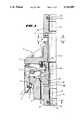
- FIG. 1is a partial cross-sectional view of a first example of apparatus to remove a wellhead.
- FIG. 2is a cross-sectional view along the line A--A in FIG. 1;
- FIG. 3is a cross-sectional view along the line Y--Y in FIG. 1;
- FIG. 4is a cross-sectional view along the line X--X in FIG. 1;
- FIG. 5is a partial cross-sectional view of a second example of apparatus to remove a wellhead
- FIG. 6Ais a detailed schematic view of an engagement and disengagement mechanism for use in the apparatus shown in FIG. 5;
- FIG. 6Bis a view along the line B--B in FIG. 6A.
- FIG. 7is a schematic diagram showing the apparatus of FIG. 5 in use.
- FIG. 1shows a wellhead 1 and a wellhead removal tool 2 which is attached to the wellhead 1 by means of three engagement arms 3 (only one of which is shown).
- the engagement arm 3attaches on to an external profile 4 of the wellhead 1.
- the engagement arms 3are mounted in a protective skirt 5 by means of a pivot 6.
- the pivot 6enables the engagement arm 3 to pivot from an engaged position where it engages the wellhead 1 to a disengaged position, shown in phantom in FIG. 1.
- the engagement arm 3is biased towards the disengaged position by means of a helical spring 50.
- an upper housing 7Mounted on top of the protective skirt 5 and above the engagement arm 3 there is an upper housing 7.
- the skirt 5is bolted to the upper housing 7 and separated from the upper housing by a number of spacers (not shown) located circumferentially around the tool 2 between adjacent arms 3.
- a male section 8 of a "J"-type releasable connectorAt the top end of the upper housing 7 is a male section 8 of a "J"-type releasable connector.
- a corresponding female section 9 of the releasable connectorforms part of an upper shaft housing 10.
- the female section 9 of the releasable connectorhas two female co-operating sections 19 which co-operate with two male co-operating sections 12 (see FIG. 4) to releasably connect the upper shaft housing 10 to the upper housing 7.
- the male co-operating sections 12each comprise a shoulder 13 and an entrance 14. The shoulder 13 limits the relative rotational movement between the female co-operating sections 19 and the male co-operating sections 12 after the female co-operating sections 19 have been inserted into the entrances 14 in the male sections 12.
- each of the female co-operating members 19are situated diametrically opposite each other and are separated by angles of 100 degrees so that each female co-operating section 19 subtends an angle of 80 degrees.
- the male co-operating sections 12are situated diametrically opposite each other and are separated by an angle of 85 degrees so that each male co-operating section 12 subtends an angle of 95 degrees.
- the angle subtended by each male co-operating section 12 from the entrance end 14 to the lock shoulder 13is 80 degrees.
- a square shoulder 15which is mounted on the shaft 11 by means of the bearings 16.
- the bearings 16may be bronze bearings or alternatively, radial glazier bearings.
- the square shoulder 15is attached to a lower shaft housing 17 by means of a set of bronze thrust bearings 18.
- the bronze thrust bearings 18 and the bearings 16enable the lower shaft housing 17 and the shaft 11 to be rotated relative to the square shoulder 15 so that the square shoulder 15 remains stationary with respect to the engagement arm 3, the protective skirt 5 and the upper housing 7, when the upper housing 7 is not connected to the upper shaft housing 10 by means of the releasable connector.
- the upper shaft housing 10 and the lower shaft housing 17are connected to the shaft 11 by means of double securing anti-backoff cotter devices 20.
- the device 20 connecting the lower shaft housing 17 to the shaft 11is shown in more detail in FIG. 2, where it can be seen that the cotter device 20 comprises two sections 21, 22 and a securing pin 30 which are located in a through bore 23 in the lower shaft housing 17.
- the section 21has a threaded pin section 24 which fits into a square threaded hole 25 in the section 22.
- the securing pin 30also connects the sections 20, 21.
- each cotter device 20engages a recess 26 formed in the shaft 11. This ensures that the shaft housings 10, 17, rotate with the shaft 11 when the shaft 11 is rotated. As the cotter device is double secured, there is very little likelihood of either of the shaft housings 10, 17 becoming disengaged from the shaft 11.
- the upper shaft housing 10is connected to the upper housing 7 by means of the male and female releasable connector sections 8, 9.
- the wellhead removal tool 2is then lowered on to a wellhead 1 so that the lower housing 17 and the shaft 11 enter the centre of the wellhead 1 and so that the protective skirt 5 encircles the top of the wellhead 1 and the engagement arms 3 which are biased to the disengages position by the springs 50, pass over the sides of the wellhead 1.
- the shaft 11is then rotated anti-clockwise through 80 degrees so that the female co-operating sections 19 disengage from the male co-operating sections 12.
- the shaft 11is then tensioned upwards and this causes the upper shaft housing 10 to separate from the upper housing 7.
- Thisalso draws the lower shaft housing 17 upwards which in turn pushes the square shoulder 15 up against a co-operating surface 27 of the engagement arm 3.
- Thisforces the engagement arm 3 to rotate about the pivot pin 6, against the biassing action of the spring 50, so that the engagement arm 3 engages with the external profile 4 of the wellhead 1.
- the shaft 11can be tensioned up to the required tension for cutting without the tool 2 separating from the wellhead 1.
- the shaft 11When the required tension is reached the shaft 11 is rotated in order to operate a conventional cutter device (not shown) which is attached to the bottom of the shaft 11.
- the cutter devicecuts a casing on which the wellhead 1 rests.
- the cutter devicehas cut the casing rotation of the shaft 11 is stopped and the shaft 11 is tensioned further in order to pull the wellhead 1 away from the sea-bed and the cut casing by means of the engagement arms 3.
- the apparatus shown in FIG. 5is similar to the apparatus shown in FIG. 1 and identical reference numerals indicate equivalent parts of the apparatus.
- the main difference with the apparatus shown in FIG. 5is that it is designed to cut the casing by operating in a compression mode, as opposed to a tension mode.
- the square shoulder 15forms part of an outer shaft 41.
- a cutter 60 and a stabiliser 67are attached to the lower end of an inner drive shaft 68 which is located coaxially within the shaft 41.
- the drive shaft 68is rotated within the shaft 41 by means of a conventional marine swivel device 65 which is connected to a string 66 which extends upwards to a rig platform (not shown).
- the marine swivel device 65co-operates with the upper end of the shaft 41 when the apparatus is compressed to enable the shaft 41 to remain stationary with respect to the engagement ar: ; 3 while the inner drive shaft 68 rotates.
- spacers 55are shown in FIG. 5 which separate the skirt 5 from the upper housing 7 and through which bolts 56 pass to bolt the skirt 5 to the upper housing 7.
- three keys 28are provided on the outside surface of the square shoulder 15 and co-operating slots 35, 36 are provided in a main body housing 29 and a thrust adapter 31 respectively of the tool 2 and this is shown in more detail in FIGS. 6A and 6B.
- the thrust adapter 31is fixed to the shaft 41 and so the slots 36 in the thrust adapter 31 are always engaged with the respective keys 28. Rotation of the shaft 41 in an anti-clockwise direction causes the square shoulder 15 and hence the keys 28 to rotate so that they may be aligned with the respective slots 35 in the main body housing 29.
- the shaft 41 and the square shoulder 15may be moved upwards to the position shown in FIG. 5, where the square shoulder 15 has pivoted the arms 3 to the engaged position adjacent the biassing action of the spring 50.
- the main body housing 29also has a lug 51 on its lower edge adjacent each slot 35.
- the lugs 51provide a positive stop for alignment and misalignment of the keys 28 with the slots 35.
- there is also a recess 52 adjacent each lug 51which co-operates with the top edge of each key 28 to help prevent the keys 28 being jarred into alignment with the slots 35 during lowering of the tool on to the wellhead 1. This would cause the square shoulder 15 to move up and pivot the arms to the engaged position prematurely. If this happened, the tool 2 would not engage the wellhead 1 properly.
- the tool 2is lowered on to a wellhead 1 and the drive shaft is compressed downwards so that the cutter 60 may be activated, via the marine swivel 65 which co-operates with the shaft 41 in order to cut the casing 61.
- rotation of the drive shaftis stopped and the shaft 41 is rotated in order to align the keys 28 with the slots 35, so that the square shoulder 15 may move upwards to pivot the engagement arms 3 to the engaged position.
- the upward tension on the shaft 41can be increased as desired in order to pull the wellhead 1 away from the sea-bed 62.
- the shaft 41is pushed downwards in order to disengage the square shoulder 15 from the engagement arms 3 and allow the spring 50 to pivot the engagement arms 3 to the disengaged position.
- the shaft 41is rotated to misalign the keys 28 and the slots 35.
- the top edge 37 of the key 28is then prevented from moving up by the lower edge of the main body housing 29 and hence the square shoulder 15 is prevented from moving up and pivoting the engagement arms 3 to the engaged position when the shaft 11 is pulled upwards. This enables the shaft 41 to be pulled upwards without the engagement arms 3 engaging the external profile 4 of the wellhead 1 so that the tool 2 may be recovered from the wellhead when it is not possible to remove the wellhead after the casing has been cut.
- the inventionhas the advantage that it is not necessary to exert a force on the interior of the wellhead 1 and so damage to the interior of the wellhead is avoided by only exerting a force on the outside of the wellhead 1 via the engagement arms 3.
- the three engagement arms 3are situated at 120 degree intervals around the circumference of the tool 2 and this gives optimum distribution of pulling forces between the wellhead 1 and each engagement arm 3.
- the apparatus described aboveincorporates a cutting tool, the apparatus could be used without the cutting mechanism as a simple wellhead latch device.
Landscapes
- Life Sciences & Earth Sciences (AREA)
- Engineering & Computer Science (AREA)
- Geology (AREA)
- Mining & Mineral Resources (AREA)
- Physics & Mathematics (AREA)
- Environmental & Geological Engineering (AREA)
- Fluid Mechanics (AREA)
- General Life Sciences & Earth Sciences (AREA)
- Geochemistry & Mineralogy (AREA)
- Marine Sciences & Fisheries (AREA)
- Mechanical Engineering (AREA)
- Excavating Of Shafts Or Tunnels (AREA)
- Recording Measured Values (AREA)
- Impression-Transfer Materials And Handling Thereof (AREA)
- Electronic Switches (AREA)
Abstract
Description
Claims (9)
Applications Claiming Priority (4)
| Application Number | Priority Date | Filing Date | Title |
|---|---|---|---|
| GB898917818AGB8917818D0 (en) | 1989-08-03 | 1989-08-03 | Apparatus for recovering a well-head |
| GB8917818 | 1989-08-03 | ||
| GB8918198 | 1989-08-09 | ||
| GB898918198AGB8918198D0 (en) | 1989-08-09 | 1989-08-09 | Apparatus for recovering a well-head |
Publications (1)
| Publication Number | Publication Date |
|---|---|
| US5146989Atrue US5146989A (en) | 1992-09-15 |
Family
ID=26295703
Family Applications (1)
| Application Number | Title | Priority Date | Filing Date |
|---|---|---|---|
| US07/671,812Expired - LifetimeUS5146989A (en) | 1989-08-03 | 1990-08-02 | Apparatus for recovering a wellhead |
Country Status (6)
| Country | Link |
|---|---|
| US (1) | US5146989A (en) |
| EP (1) | EP0436706B1 (en) |
| CA (1) | CA2036376C (en) |
| DE (1) | DE69007060T2 (en) |
| NO (1) | NO178940C (en) |
| WO (1) | WO1991002138A1 (en) |
Cited By (10)
| Publication number | Priority date | Publication date | Assignee | Title |
|---|---|---|---|---|
| US6029745A (en)* | 1998-01-22 | 2000-02-29 | Weatherford/Lamb, Inc. | Casing cutting and retrieving system |
| US6330919B1 (en)* | 1996-03-08 | 2001-12-18 | Smith International, Inc. | Method of removing wellhead assemblies and cutting assembly for use therein |
| WO2009028953A1 (en)* | 2007-08-30 | 2009-03-05 | Norse Cutting & Abandonment As | Method and device for removing the upper portion of a well |
| US7686083B1 (en) | 2007-08-31 | 2010-03-30 | Dwayne Emfinger | Method and apparatus for cutting off a well |
| US20100326665A1 (en)* | 2009-06-24 | 2010-12-30 | Redlinger Thomas M | Methods and apparatus for subsea well intervention and subsea wellhead retrieval |
| US9222328B2 (en) | 2012-12-07 | 2015-12-29 | Smith International, Inc. | Wellhead latch and removal systems |
| WO2017192043A1 (en)* | 2016-05-06 | 2017-11-09 | Umac As | A device for providing a separating cut in a material of a wellhead of a hydrocarbon well |
| WO2018132353A1 (en)* | 2017-01-10 | 2018-07-19 | Weatherford Technology Holdings, Llc | Tension cutting casing and wellhead retrieval system |
| US10160528B2 (en)* | 2014-09-19 | 2018-12-25 | Aker Solutions As | Handling device for an installable and retrievable subsea apparatus |
| US10322912B2 (en)* | 2015-06-19 | 2019-06-18 | Weatherford U.K. Limited | Connector system |
Families Citing this family (4)
| Publication number | Priority date | Publication date | Assignee | Title |
|---|---|---|---|---|
| GB9120298D0 (en)* | 1991-09-24 | 1991-11-06 | Homco International Inc | Casing cutting and retrieving tool |
| GB9325329D0 (en)* | 1993-12-10 | 1994-02-16 | Ocean Techn Services Ltd | Offshore wellheads |
| US10125555B2 (en) | 2013-05-02 | 2018-11-13 | Weatherford Technology Holdings, Llc | Tubular handling tool |
| GB2605618B (en)* | 2021-04-07 | 2025-03-26 | Subsea Pressure Controls Ltd | A Subsea Wellhead Clamp Assembly |
Citations (4)
| Publication number | Priority date | Publication date | Assignee | Title |
|---|---|---|---|---|
| US3325190A (en)* | 1963-07-15 | 1967-06-13 | Fmc Corp | Well apparatus |
| US3513911A (en)* | 1968-05-24 | 1970-05-26 | Shell Oil Co | Offshore well workover method |
| US3589441A (en)* | 1968-04-01 | 1971-06-29 | North American Rockwell | Deep water operating and servicing system for operating and servicing marine wells |
| US4181196A (en)* | 1977-06-23 | 1980-01-01 | Exxon Production Research Company | Method and apparatus for recovery of subsea well equipment |
Family Cites Families (2)
| Publication number | Priority date | Publication date | Assignee | Title |
|---|---|---|---|---|
| FR2253976B1 (en)* | 1973-12-05 | 1976-11-19 | Subsea Equipment Ass Ltd | |
| GB2165286B (en)* | 1984-10-06 | 1988-02-03 | Deepwater Oil Services | Cutting and recovery tool |
- 1990
- 1990-08-02EPEP90911869Apatent/EP0436706B1/ennot_activeExpired - Lifetime
- 1990-08-02USUS07/671,812patent/US5146989A/ennot_activeExpired - Lifetime
- 1990-08-02CACA002036376Apatent/CA2036376C/ennot_activeExpired - Lifetime
- 1990-08-02DEDE69007060Tpatent/DE69007060T2/ennot_activeExpired - Lifetime
- 1990-08-02WOPCT/GB1990/001203patent/WO1991002138A1/enactiveIP Right Grant
- 1991
- 1991-04-02NONO911285Apatent/NO178940C/ennot_activeIP Right Cessation
Patent Citations (4)
| Publication number | Priority date | Publication date | Assignee | Title |
|---|---|---|---|---|
| US3325190A (en)* | 1963-07-15 | 1967-06-13 | Fmc Corp | Well apparatus |
| US3589441A (en)* | 1968-04-01 | 1971-06-29 | North American Rockwell | Deep water operating and servicing system for operating and servicing marine wells |
| US3513911A (en)* | 1968-05-24 | 1970-05-26 | Shell Oil Co | Offshore well workover method |
| US4181196A (en)* | 1977-06-23 | 1980-01-01 | Exxon Production Research Company | Method and apparatus for recovery of subsea well equipment |
Non-Patent Citations (1)
| Title |
|---|
| Brochure of TAM International, published on Composite Catalogue, 1980/81, p. 6740.* |
Cited By (21)
| Publication number | Priority date | Publication date | Assignee | Title |
|---|---|---|---|---|
| US6330919B1 (en)* | 1996-03-08 | 2001-12-18 | Smith International, Inc. | Method of removing wellhead assemblies and cutting assembly for use therein |
| US6554073B2 (en)* | 1996-03-08 | 2003-04-29 | Smith International, Inc. | Method and apparatus for removing wellhead assemblies |
| US6029745A (en)* | 1998-01-22 | 2000-02-29 | Weatherford/Lamb, Inc. | Casing cutting and retrieving system |
| WO1999037877A3 (en)* | 1998-01-22 | 2000-09-08 | Weatherford Lamb | System, apparatus and method for facilitating retrieval of an item from a well |
| EP1312752A3 (en)* | 1998-01-22 | 2006-05-24 | Weatherford/Lamb, Inc. | System, apparatus and method for facilitating retrieval of an item from a well |
| GB2463849B (en)* | 2007-08-30 | 2011-12-07 | Norse Cutting & Abandonment As | Method and device for removing the upper portion of a well |
| WO2009028953A1 (en)* | 2007-08-30 | 2009-03-05 | Norse Cutting & Abandonment As | Method and device for removing the upper portion of a well |
| GB2463849A (en)* | 2007-08-30 | 2010-03-31 | Norse Cutting & Abandonment As | Method and device for removing the upper portion of a well |
| AU2008293123B2 (en)* | 2007-08-30 | 2011-09-29 | Claxton Engineering Services AS | Method and device for removing the upper portion of a well |
| US7686083B1 (en) | 2007-08-31 | 2010-03-30 | Dwayne Emfinger | Method and apparatus for cutting off a well |
| US8662182B2 (en)* | 2009-06-24 | 2014-03-04 | Weatherford/Lamb, Inc. | Methods and apparatus for subsea well intervention and subsea wellhead retrieval |
| US8307903B2 (en)* | 2009-06-24 | 2012-11-13 | Weatherford / Lamb, Inc. | Methods and apparatus for subsea well intervention and subsea wellhead retrieval |
| US20100326665A1 (en)* | 2009-06-24 | 2010-12-30 | Redlinger Thomas M | Methods and apparatus for subsea well intervention and subsea wellhead retrieval |
| US9222328B2 (en) | 2012-12-07 | 2015-12-29 | Smith International, Inc. | Wellhead latch and removal systems |
| US10160528B2 (en)* | 2014-09-19 | 2018-12-25 | Aker Solutions As | Handling device for an installable and retrievable subsea apparatus |
| US10322912B2 (en)* | 2015-06-19 | 2019-06-18 | Weatherford U.K. Limited | Connector system |
| WO2017192043A1 (en)* | 2016-05-06 | 2017-11-09 | Umac As | A device for providing a separating cut in a material of a wellhead of a hydrocarbon well |
| WO2017192045A1 (en)* | 2016-05-06 | 2017-11-09 | Umac As | A device for operation on a wellhead of a hydrocarbon well |
| WO2018132353A1 (en)* | 2017-01-10 | 2018-07-19 | Weatherford Technology Holdings, Llc | Tension cutting casing and wellhead retrieval system |
| US10385640B2 (en) | 2017-01-10 | 2019-08-20 | Weatherford Technology Holdings, Llc | Tension cutting casing and wellhead retrieval system |
| AU2018207075B2 (en)* | 2017-01-10 | 2022-12-08 | Weatherford Technology Holdings, Llc | Tension cutting casing and wellhead retrieval system |
Also Published As
| Publication number | Publication date |
|---|---|
| DE69007060T2 (en) | 1994-06-09 |
| EP0436706B1 (en) | 1994-03-02 |
| NO178940C (en) | 1996-07-03 |
| DE69007060D1 (en) | 1994-04-07 |
| CA2036376C (en) | 1998-08-18 |
| EP0436706A1 (en) | 1991-07-17 |
| NO911285D0 (en) | 1991-04-02 |
| NO178940B (en) | 1996-03-25 |
| CA2036376A1 (en) | 1991-02-04 |
| NO911285L (en) | 1991-04-02 |
| WO1991002138A1 (en) | 1991-02-21 |
Similar Documents
| Publication | Publication Date | Title |
|---|---|---|
| US5146989A (en) | Apparatus for recovering a wellhead | |
| US4703802A (en) | Cutting and recovery tool | |
| US7188674B2 (en) | Downhole milling machine and method of use | |
| US7591315B2 (en) | Subsea riser disconnect and method | |
| US4967844A (en) | Selectively operable ball valve and production packer system | |
| CA1067399A (en) | Well flow control system and method | |
| US5318115A (en) | Casing cutting and retrieving tool | |
| US6557637B1 (en) | Subsea riser disconnect and method | |
| AU2001259532A1 (en) | Subsea riser disconnect and method | |
| US6793019B2 (en) | Tapered ramp positive lock latch mechanism | |
| US4749046A (en) | Well drilling and completion apparatus | |
| US6907932B2 (en) | Control pod latchdown mechanism | |
| US4691781A (en) | Well drilling and completion apparatus | |
| US8403054B2 (en) | Torque tripping mechanism for a valve | |
| US4073511A (en) | Coupling assembly for submarine casing sections | |
| US4289206A (en) | Remote multiple string well completion | |
| US4732214A (en) | Subsea production test valve assembly | |
| US4429902A (en) | Remotely releasable connector | |
| US4796698A (en) | Landing nipple and plug | |
| GB2087957A (en) | Subsurface control valve apparatus ia-c | |
| RU2015303C1 (en) | Device for pulling the equipment from wellhead of oil well | |
| US11371294B2 (en) | Releasable ratchet latch connector | |
| US4022281A (en) | Method and apparatus for orienting equipment in a well | |
| US4749045A (en) | Well drilling and completion apparatus | |
| GB2218444A (en) | Casing hanger and packoff running tool |
Legal Events
| Date | Code | Title | Description |
|---|---|---|---|
| AS | Assignment | Owner name:HOMCO INTERNATIONAL INC., 4710, BELLAIRE BLVD., ST Free format text:ASSIGNMENT OF ASSIGNORS INTEREST.;ASSIGNOR:ROUSE, GEOFFREY O.;REEL/FRAME:005686/0650 Effective date:19910226 | |
| STCF | Information on status: patent grant | Free format text:PATENTED CASE | |
| AS | Assignment | Owner name:WEATHERFORD U.S., INC., TEXAS Free format text:ASSIGNMENT OF ASSIGNORS INTEREST;ASSIGNOR:HOMCO INTERNATIONAL, INC.;REEL/FRAME:006663/0918 Effective date:19930331 | |
| AS | Assignment | Owner name:TEXAS COMMERCE BANK NATIONAL ASSOICATION, TEXAS Free format text:SECURITY INTEREST;ASSIGNOR:WEATHERFORD U.S., INC.;REEL/FRAME:006677/0420 Effective date:19930331 | |
| CC | Certificate of correction | ||
| AS | Assignment | Owner name:WEATHERFORD U.S., INC., TEXAS Free format text:RELEASE FROM SECURITY AGREEMENT;ASSIGNOR:TEXAS COMMERCE BANK NATIONAL ASSOCIATION;REEL/FRAME:006968/0187 Effective date:19940415 | |
| FPAY | Fee payment | Year of fee payment:4 | |
| FPAY | Fee payment | Year of fee payment:8 | |
| FPAY | Fee payment | Year of fee payment:12 | |
| AS | Assignment | Owner name:WEATHERFORD/LAMB, INC., TEXAS Free format text:ASSIGNMENT OF ASSIGNORS INTEREST;ASSIGNOR:WEATHERFORD U.S., L.P.;REEL/FRAME:016016/0867 Effective date:20050517 |