US5146902A - Positive pressure canister purge system integrity confirmation - Google Patents
Positive pressure canister purge system integrity confirmationDownload PDFInfo
- Publication number
- US5146902A US5146902AUS07/801,322US80132291AUS5146902AUS 5146902 AUS5146902 AUS 5146902AUS 80132291 AUS80132291 AUS 80132291AUS 5146902 AUS5146902 AUS 5146902A
- Authority
- US
- United States
- Prior art keywords
- canister
- pressure
- positive pressure
- engine
- intake manifold
- Prior art date
- Legal status (The legal status is an assumption and is not a legal conclusion. Google has not performed a legal analysis and makes no representation as to the accuracy of the status listed.)
- Expired - Lifetime
Links
- 238000010926purgeMethods0.000titleclaimsabstractdescription68
- 238000012790confirmationMethods0.000title1
- 238000012360testing methodMethods0.000claimsabstractdescription23
- 238000002405diagnostic procedureMethods0.000claimsabstractdescription12
- 238000002485combustion reactionMethods0.000claimsdescription35
- 239000000446fuelSubstances0.000claimsdescription32
- 239000002828fuel tankSubstances0.000claimsdescription21
- 230000007423decreaseEffects0.000claimsdescription14
- 238000000034methodMethods0.000claimsdescription11
- 230000011664signalingEffects0.000claimsdescription9
- 238000001514detection methodMethods0.000claimsdescription5
- 239000007788liquidSubstances0.000claimsdescription3
- 239000000203mixtureSubstances0.000claims10
- XLYOFNOQVPJJNP-UHFFFAOYSA-NwaterSubstancesOXLYOFNOQVPJJNP-UHFFFAOYSA-N0.000description6
- 239000003570airSubstances0.000description4
- 230000008901benefitEffects0.000description3
- 238000010276constructionMethods0.000description3
- 238000009529body temperature measurementMethods0.000description2
- OKTJSMMVPCPJKN-UHFFFAOYSA-NCarbonChemical compound[C]OKTJSMMVPCPJKN-UHFFFAOYSA-N0.000description1
- 239000012080ambient airSubstances0.000description1
- 230000033228biological regulationEffects0.000description1
- 229910052799carbonInorganic materials0.000description1
- 239000002826coolantSubstances0.000description1
- 230000008878couplingEffects0.000description1
- 238000010168coupling processMethods0.000description1
- 238000005859coupling reactionMethods0.000description1
- 238000010586diagramMethods0.000description1
- 239000012530fluidSubstances0.000description1
- 239000003502gasolineSubstances0.000description1
- 230000006698inductionEffects0.000description1
- 238000005259measurementMethods0.000description1
- 230000009467reductionEffects0.000description1
- 230000004044responseEffects0.000description1
- 238000011144upstream manufacturingMethods0.000description1
Images
Classifications
- F—MECHANICAL ENGINEERING; LIGHTING; HEATING; WEAPONS; BLASTING
- F02—COMBUSTION ENGINES; HOT-GAS OR COMBUSTION-PRODUCT ENGINE PLANTS
- F02M—SUPPLYING COMBUSTION ENGINES IN GENERAL WITH COMBUSTIBLE MIXTURES OR CONSTITUENTS THEREOF
- F02M25/00—Engine-pertinent apparatus for adding non-fuel substances or small quantities of secondary fuel to combustion-air, main fuel or fuel-air mixture
- F02M25/08—Engine-pertinent apparatus for adding non-fuel substances or small quantities of secondary fuel to combustion-air, main fuel or fuel-air mixture adding fuel vapours drawn from engine fuel reservoir
- F02M25/0809—Judging failure of purge control system
- F02M25/0818—Judging failure of purge control system having means for pressurising the evaporative emission space
Definitions
- This inventionrelates generally to evaporative emission control systems that are used in automotive vehicles to control the emission of volatile fuel vapors. Specifically the invention relates to an on-board diagnostic system for determining if a leak is present in a portion of the system which includes the fuel tank and the canister that collects volatile fuel vapors from the tank's headspace.
- a typical evaporative emission control system in a modern automotive vehiclecomprises a vapor collection canister that collects volatile fuel vapors generated in the fuel tank.
- the canisteris purged to the engine intake manifold by means of a canister purge system that comprises a canister purge solenoid valve that is operated by an engine management computer.
- the canister purge valveis opened in an amount determined by the computer to allow the intake manifold vacuum to draw vapors from the canister through the valve into the engine.
- U.S. governmental regulationsrequire that certain future automobiles that are powered by volatile fuel such as gasoline have their evaporative emission control systems equipped with on-board diagnostic capability for determining if a leak is present in a portion of the system which includes the fuel tank and the canister.
- One proposed response to that requirementis to connect a normally open solenoid valve in the canister vent, and to energize the solenoid when a diagnostic test is to be conducted.
- a certain vacuumis drawn in a portion of the system which includes the tank headspace and the canister, and with the canister and the tank headspace not being vented due to the closing of the canister vent, a certain loss of vacuum over a certain time will be deemed due to a leak. Loss of vacuum is detected by a transducer mounted on the fuel tank.
- the invention disclosed in commonly assigned application Ser. No. 07/770,009, filed Oct. 2, 1991,provides a solution to the leak detection problem which is significantly less costly.
- the key to that solutionis a new and unique vacuum regulator/sensor which is disposed in the conduit between the canister purge solenoid and the canister.
- the vacuum regulator/sensoris like a vacuum regulator but with the inclusion of a switch that is used to provide a signal indicating the presence or the absence of a leak.
- a diagnostic testis performed by closing the tank vent and using the engine manifold vacuum to draw, via the canister purge solenoid valve and the vacuum regulator/sensor, a specified vacuum in the tank headspace and canister. Upon the requisite vacuum having been drawn, the vacuum regulator/sensor closes to trap the drawn vacuum. If unacceptable leakage is present, a certain amount of vacuum will be lost within a certain amount of time, and that occurrence causes the switch of the vacuum regulator/sensor to give a signal indicating that condition.
- the present inventionrelates to a diagnostic system and method for evaluating the integrity of a portion of the canister purge system that includes the tank and canister by means of positive pressurization rather than negative pressurization (i.e., rather than by drawing vacuum).
- a diagnostic system and methodmay afford certain advantages over the system and method described in the aforementioned commonly assigned patent application.
- the evaporative emission control systemmay be diagnosed either with or without the automobile's engine running.
- One means to perform positive pressurization of the fuel tank's headspace and the canisteris a devoted electric-operated air pump, which can be of quite simple construction, and therefore relatively inexpensive. If the vehicle already contains a source of suitably pressurized air, that could constitute another means, thereby eliminating the need for a separate devoted pump.
- a further benefit of positive pressurization over negative pressurizationis that the increased pressure suppresses the rate of fuel vapor generation in the tank, and such attenuation of fuel vapor generation during a diagnostic test reduces the likelihood that the test will give, under hot weather conditions which promote fuel vapor generation, a false signal that would erroneously confirm the integrity of the canister and tank whereas the same test during cold weather would indicate a leak.
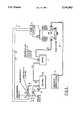
- FIG. 1is a schematic diagram of a representative canister purge system, including a diagnostic system embodying principles of the present invention.
- FIG. 1shows a representative canister purge system 10 embodying principles of the invention.
- System 10comprises a canister purge solenoid valve 12 (CPS valve 12), and a carbon canister 14, associated with the intake manifold 15 of an automotive vehicle internal combustion engine and with a fuel tank 16 of the automotive vehicle which holds a supply of volatile liquid fuel for powering the engine.
- CPS valve 12is under the control of an engine management computer 18 for the engine.
- a pressure/vacuum relief valve 19is associated with canister 14. It is normally closed, but opens at a predetermined positive pressure, such as +10 inches of water for example, to prevent excessive positive pressure in the canister, and it also opens at a predetermined negative pressure, such as 31 2 inches of water for example, to prevent excessive negative pressure in the canister.
- the canister purge systemoperates in conventional manner, and may be briefly described as follows. Under conditions conducive to purging, computer 18 causes the normally closed CPS valve 12 to open in a controlled manner. The result is that a certain amount of the engine manifold vacuum is delivered to canister 14 causing collected vapors to flow from the canister through the CPS valve to the engine manifold where they entrain with the induction fluid entering the engine's combustion chamber space to be ultimately combusted. To the extent that the pressure might seek to fall below -2 inches of water, relief valve 19 opens to allow the purge flow to continue without further pressure reduction in the tank/canister. Alternatively, relief valve 19 could be replaced by another device, such as a normally open solenoid operated vent valve which is operated closed for the diagnostic test.
- a pressure/sensing module 20is associated with the system. It comprises an electric operated pump (blower motor) 22, a check valve 24, and a pressure sensing switch 26 having a set of contacts 28, which in the exemplary embodiment of FIG. 1 are normally open.
- Pump 22has an air inlet 30 that is communicated to ambient air and an air outlet 32 that is communicated to an inlet of check valve 24.
- An outlet of the check valveis communicated to the headspace of tank 16.
- Pressure sensing switch 26has a pressure sensing port 34 that is communicated to the tank headspace. When the pressure sensed by switch 26 at port 34 is below a set point, contacts 28 are open; when the pressure sensed by switch 26 at port 34 is above the set point, contacts 28 are closed.
- the switchis intentionally designed and calibrated to have a certain hysteresis at its set point.
- the switchmay close contacts 28 at a certain high positive pressure, say +5 inches of water, which is below the positive pressure at which relief valve 19 opens, but re-open them only after the pressure has fallen a predetermined amount below the pressure that closed them, for example re-opening the contacts at +2 inches of water.
- Module 20is also electrically connected with computer 18.
- One electric circuit connection 36 coupling module 20 with computer 18provides for the computer to control the operation of pump 22; another connection 38 provides for switch 26 to signal the computer.
- the systemfunctions in the following manner to perform a diagnostic test on the integrity against unacceptable leakage of that portion of the CPS system that is upstream of CPS valve 12.
- computer 18commands CPS valve 12 to be closed and detects whether contacts 28 are open or closed. If contacts 28 are closed, a pre-existing positive pressure condition in the tank/canister exists that will preclude the performance of the diagnostic test at that time. Accordingly, the test is deferred to a later time, and in this regard it should be mentioned that the timing at which tests are attempted is determined by various other inputs to or programs of computer 18 that need not be mentioned here.
- computer 18detects contacts 28 to be open, then the pre-existing pressure in the tank/canister is deemed suitable for the test to proceed.
- computer 18commands pump 22 to operate and thus increasingly positively pressurize the tank/canister.
- the tank/canister positive pressureshould build.
- the presence of a grossly unacceptable leak in the tank/canistercould prevent the pressure from building to a predetermined positive pressure within a predetermined time.
- a faultis indicated.
- Such faultmay be attributed to any one or more of: a gross leak in the tank/canister, a faulty connection between module 20 and computer 18, a faulty pump 22, a faulty check valve 24, or a faulty pressure switch 26. In such an event the test is terminated and a fault indication given.
- An unacceptable leakwill cause the positive pressure to drop to at least a certain preselected level within a given time; the absence of a leak or the presence of a leak that is so small as to not be deemed unacceptable will not cause the pressure to drop below that preselected level within that given time.
- Associated with computer 18is a timer which begins counting time upon detection of closure of contacts 28. If, after a certain preselected amount of time has been counted, contacts 28 remain closed, the integrity of the test-ensealed tank/canister volume is deemed to have been confirmed, and computer 18 may so indicate in any appropriate manner such by an internal flag or an external signal.
- the re-opening of the contacts during the testing timeis deemed to indicate an unacceptable leak, and such occurrence will be flagged by the computer as a fault signal or called to the attention of the vehicle operator by any suitable means such as a warning lamp on the instrument panel.
- the inventioncan enable a test to be performed at relatively small positive pressure levels in the canister and fuel tank so that the pressure will not cause deformation of properly designed canisters and tanks.
- the canister purge valveis once again operated by computer 18 in the usual way for conducting canister purging.
- the present inventionmay allow testing to proceed under higher ambient temperatures than in the case of the prior system. However, since ambient temperature or engine temperature may still influence the test to some extent, one may choose to employ a temperature sensor mounted on the fuel tank to provide a fuel temperature measurement to the computer and/or the engine coolant sensor to provide a temperature measurement to the computer. If the temperature is not below a predetermined temperature above which the generation of vapor could affect the validity of the test, the test would be deemed invalid. Valid testing would therefore occur only below the predetermined temperature.
- Principles of the inventionare also applicable to the use of an electrically operated pump to draw negative pressure, instead of positive pressure. In such a case, the directions of blower motor 30 and check valve 32 would be reversed. Pressure switch 26 would operate in analogous manner to that described above, while being arranged to look for a predetermined loss of vacuum within a predetermined time. Likewise, an analog detecting and signaling device could be used in place of the pressure switch.
Landscapes
- Engineering & Computer Science (AREA)
- Chemical & Material Sciences (AREA)
- Combustion & Propulsion (AREA)
- Mechanical Engineering (AREA)
- General Engineering & Computer Science (AREA)
- Supplying Secondary Fuel Or The Like To Fuel, Air Or Fuel-Air Mixtures (AREA)
- Testing Of Engines (AREA)
Abstract
Description
This invention relates generally to evaporative emission control systems that are used in automotive vehicles to control the emission of volatile fuel vapors. Specifically the invention relates to an on-board diagnostic system for determining if a leak is present in a portion of the system which includes the fuel tank and the canister that collects volatile fuel vapors from the tank's headspace.
A typical evaporative emission control system in a modern automotive vehicle comprises a vapor collection canister that collects volatile fuel vapors generated in the fuel tank. During conditions conducive to purging, the canister is purged to the engine intake manifold by means of a canister purge system that comprises a canister purge solenoid valve that is operated by an engine management computer. The canister purge valve is opened in an amount determined by the computer to allow the intake manifold vacuum to draw vapors from the canister through the valve into the engine.
U.S. governmental regulations require that certain future automobiles that are powered by volatile fuel such as gasoline have their evaporative emission control systems equipped with on-board diagnostic capability for determining if a leak is present in a portion of the system which includes the fuel tank and the canister. One proposed response to that requirement is to connect a normally open solenoid valve in the canister vent, and to energize the solenoid when a diagnostic test is to be conducted. A certain vacuum is drawn in a portion of the system which includes the tank headspace and the canister, and with the canister and the tank headspace not being vented due to the closing of the canister vent, a certain loss of vacuum over a certain time will be deemed due to a leak. Loss of vacuum is detected by a transducer mounted on the fuel tank. Because of the nature of the construction of typical fuel tanks, a limit is imposed on the magnitude of vacuum that can be drawn. Too large a vacuum will result in deformation and render the measurement meaningless. In order to avoid this problem, a relatively costly vacuum transducer is required. Since typical automotive vehicles are powered by internal combustion engines which draw intake manifold vacuum, such vacuum may be used for performance of the diagnostic test, but typically this requires that the engine be running in order to perform the test.
The invention disclosed in commonly assigned application Ser. No. 07/770,009, filed Oct. 2, 1991, provides a solution to the leak detection problem which is significantly less costly. The key to that solution is a new and unique vacuum regulator/sensor which is disposed in the conduit between the canister purge solenoid and the canister. The vacuum regulator/sensor is like a vacuum regulator but with the inclusion of a switch that is used to provide a signal indicating the presence or the absence of a leak. A diagnostic test is performed by closing the tank vent and using the engine manifold vacuum to draw, via the canister purge solenoid valve and the vacuum regulator/sensor, a specified vacuum in the tank headspace and canister. Upon the requisite vacuum having been drawn, the vacuum regulator/sensor closes to trap the drawn vacuum. If unacceptable leakage is present, a certain amount of vacuum will be lost within a certain amount of time, and that occurrence causes the switch of the vacuum regulator/sensor to give a signal indicating that condition.
The present invention relates to a diagnostic system and method for evaluating the integrity of a portion of the canister purge system that includes the tank and canister by means of positive pressurization rather than negative pressurization (i.e., rather than by drawing vacuum). In certain canister purge systems, such a diagnostic system and method may afford certain advantages over the system and method described in the aforementioned commonly assigned patent application.
For example, it may be possible to omit the normally open solenoid operated vent valve that must be operated closed when the diagnostic test is to be performed. Certain types of leaks, for example cracked hoses and faulty gas caps, may be more susceptible to successful detection. Moreover, the evaporative emission control system may be diagnosed either with or without the automobile's engine running. One means to perform positive pressurization of the fuel tank's headspace and the canister is a devoted electric-operated air pump, which can be of quite simple construction, and therefore relatively inexpensive. If the vehicle already contains a source of suitably pressurized air, that could constitute another means, thereby eliminating the need for a separate devoted pump.
A further benefit of positive pressurization over negative pressurization is that the increased pressure suppresses the rate of fuel vapor generation in the tank, and such attenuation of fuel vapor generation during a diagnostic test reduces the likelihood that the test will give, under hot weather conditions which promote fuel vapor generation, a false signal that would erroneously confirm the integrity of the canister and tank whereas the same test during cold weather would indicate a leak.
Further specific details of the construction and arrangements of the inventive system, and of the method of operation thereof, along with additional features and benefits, will be presented in the ensuing description.
A drawing accompanies this disclosure and portrays a presently preferred embodiment of the invention according to the best mode presently contemplated for carrying out the invention.
FIG. 1 is a schematic diagram of a representative canister purge system, including a diagnostic system embodying principles of the present invention.
FIG. 1 shows a representativecanister purge system 10 embodying principles of the invention.System 10 comprises a canister purge solenoid valve 12 (CPS valve 12), and acarbon canister 14, associated with theintake manifold 15 of an automotive vehicle internal combustion engine and with afuel tank 16 of the automotive vehicle which holds a supply of volatile liquid fuel for powering the engine.CPS valve 12 is under the control of anengine management computer 18 for the engine. A pressure/vacuum relief valve 19 is associated withcanister 14. It is normally closed, but opens at a predetermined positive pressure, such as +10 inches of water for example, to prevent excessive positive pressure in the canister, and it also opens at a predetermined negative pressure, such as 31 2 inches of water for example, to prevent excessive negative pressure in the canister.
The canister purge system operates in conventional manner, and may be briefly described as follows. Under conditions conducive to purging,computer 18 causes the normally closedCPS valve 12 to open in a controlled manner. The result is that a certain amount of the engine manifold vacuum is delivered to canister 14 causing collected vapors to flow from the canister through the CPS valve to the engine manifold where they entrain with the induction fluid entering the engine's combustion chamber space to be ultimately combusted. To the extent that the pressure might seek to fall below -2 inches of water,relief valve 19 opens to allow the purge flow to continue without further pressure reduction in the tank/canister. Alternatively,relief valve 19 could be replaced by another device, such as a normally open solenoid operated vent valve which is operated closed for the diagnostic test.
In accordance with the invention, a pressure/sensing module 20 is associated with the system. It comprises an electric operated pump (blower motor) 22, acheck valve 24, and apressure sensing switch 26 having a set ofcontacts 28, which in the exemplary embodiment of FIG. 1 are normally open.Pump 22 has anair inlet 30 that is communicated to ambient air and anair outlet 32 that is communicated to an inlet ofcheck valve 24. An outlet of the check valve is communicated to the headspace oftank 16.Pressure sensing switch 26 has apressure sensing port 34 that is communicated to the tank headspace. When the pressure sensed byswitch 26 atport 34 is below a set point,contacts 28 are open; when the pressure sensed byswitch 26 atport 34 is above the set point,contacts 28 are closed. However, the switch is intentionally designed and calibrated to have a certain hysteresis at its set point. For example, the switch may closecontacts 28 at a certain high positive pressure, say +5 inches of water, which is below the positive pressure at whichrelief valve 19 opens, but re-open them only after the pressure has fallen a predetermined amount below the pressure that closed them, for example re-opening the contacts at +2 inches of water.
The system functions in the following manner to perform a diagnostic test on the integrity against unacceptable leakage of that portion of the CPS system that is upstream ofCPS valve 12. First,computer 18commands CPS valve 12 to be closed and detects whethercontacts 28 are open or closed. Ifcontacts 28 are closed, a pre-existing positive pressure condition in the tank/canister exists that will preclude the performance of the diagnostic test at that time. Accordingly, the test is deferred to a later time, and in this regard it should be mentioned that the timing at which tests are attempted is determined by various other inputs to or programs ofcomputer 18 that need not be mentioned here. On the other hand, ifcomputer 18 detectscontacts 28 to be open, then the pre-existing pressure in the tank/canister is deemed suitable for the test to proceed.
That being the case,computer 18 commands pump 22 to operate and thus increasingly positively pressurize the tank/canister. As the pump operates, the tank/canister positive pressure should build. However, the presence of a grossly unacceptable leak in the tank/canister could prevent the pressure from building to a predetermined positive pressure within a predetermined time. Thus, ifcontacts 28 remain open for at least a certain amount of time after the computer has issued its command to operatepump 22, a fault is indicated. Such fault may be attributed to any one or more of: a gross leak in the tank/canister, a faulty connection betweenmodule 20 andcomputer 18, afaulty pump 22, afaulty check valve 24, or afaulty pressure switch 26. In such an event the test is terminated and a fault indication given.
However, if the pressure in the tank/canister builds within a predetermined time to the setting that will causepressure switch 26 to closecontacts 28, then the test proceeds. Once closure ofswitch contacts 28 is detected bycomputer 18, the computer immediately shuts offpump 22. Checkvalve 24 functions to prevent loss of pressure back through the pump. This traps the pressure in the tank/canister, and the trapped pressure is initially essentially equal to that at whichcontacts 28 closed, i.e. +5 inches water in the example. If a leak is present in the tank/canister, positive pressure will begin to decrease. The rate at which the positive pressure decreases is a function of the severity of the leak. An unacceptable leak will cause the positive pressure to drop to at least a certain preselected level within a given time; the absence of a leak or the presence of a leak that is so small as to not be deemed unacceptable will not cause the pressure to drop below that preselected level within that given time.
Associated withcomputer 18 is a timer which begins counting time upon detection of closure ofcontacts 28. If, after a certain preselected amount of time has been counted,contacts 28 remain closed, the integrity of the test-ensealed tank/canister volume is deemed to have been confirmed, andcomputer 18 may so indicate in any appropriate manner such by an internal flag or an external signal.
On the other hand, the re-opening of the contacts during the testing time is deemed to indicate an unacceptable leak, and such occurrence will be flagged by the computer as a fault signal or called to the attention of the vehicle operator by any suitable means such as a warning lamp on the instrument panel.
It may be mentioned at this point that the invention can enable a test to be performed at relatively small positive pressure levels in the canister and fuel tank so that the pressure will not cause deformation of properly designed canisters and tanks. At the completion of a test the canister purge valve is once again operated bycomputer 18 in the usual way for conducting canister purging.
If a diagnostic test is conducted above a certain temperature, it is possible that fuel vapors may be generated in the tank at a rate that is sufficiently fast that the increase in vapor pressure will mask at least to some extent the existence of a leak. This tendency is somewhat better countered by the present invention in comparison to that of the referenced application Ser. No. 07/770,009 because the increased positive pressurization tends to attenuate the vapor generation rate. Hence, the present invention may allow testing to proceed under higher ambient temperatures than in the case of the prior system. However, since ambient temperature or engine temperature may still influence the test to some extent, one may choose to employ a temperature sensor mounted on the fuel tank to provide a fuel temperature measurement to the computer and/or the engine coolant sensor to provide a temperature measurement to the computer. If the temperature is not below a predetermined temperature above which the generation of vapor could affect the validity of the test, the test would be deemed invalid. Valid testing would therefore occur only below the predetermined temperature.
Principles of the invention are also applicable to the use of an electrically operated pump to draw negative pressure, instead of positive pressure. In such a case, the directions ofblower motor 30 andcheck valve 32 would be reversed.Pressure switch 26 would operate in analogous manner to that described above, while being arranged to look for a predetermined loss of vacuum within a predetermined time. Likewise, an analog detecting and signaling device could be used in place of the pressure switch.
Having disclosed generic principles of the invention, this application is intended to provide legal protection for all embodiments falling within the scope of the following claims.
Claims (20)
1. A canister purge system comprising a collection canister for collecting volatile fuel vapors from a fuel tank, and means for selectively purging collected fuel vapors from said, canister to an internal combustion engine's intake manifold for entrainment with a combustible mixture that passes from the manifold into combustion chamber space of the engine for combustion therein, said means including a purge flow path between said canister and intake manifold, characterized by an associated diagnostic system that detects unacceptable leakage from a portion of the canister purge system, which portion includes said canister and tank, and that comprises means for positively pressurizing said portion to a predetermined positive pressure, detecting means for detecting a certain decrease in the positive pressure, in said portion from said predetermined positive pressure indicative of unacceptable leakage from said portion, and signaling means for giving a signal indicative of such decrease.
2. A canister purge system as set forth in claim 1 characterized further in that said means for positively pressurizing said portion to a predetermined positive pressure comprises an electrically operated pump.
3. A canister purge system as set forth in claim characterized further in that said detecting means and said signaling means collectively comprise a pressure switch having a set of electrical contacts.
4. In an automotive vehicle comprising an internal combustion engine for powering the vehicle, an engine management computer for controlling certain functions associated with the operation of said engine, said comprising an intake manifold within which vacuum is created during operation of the engine, said vehicle comprising a fuel tank for containing a supply of a volatile liquid fuel for the engine, and an evaporative emission control system comprising a collection canister for collecting volatile fuel vapors from the fuel tank, and means for selectively purging collected fuel vapors from said canister to an internal combustion engine's intake manifold for entrainment with a combustible mixture that passes from the intake manifold into combustion chamber space of the engine for combustion therein, said means including a purge flow path comprising a canister purge solenoid valve that is between said canister and intake manifold and that is under the control of said engine management computer, the improvement characterized by an associated diagnostic system that detects unacceptable leakage from a portion of the evaporative emission control system which portion includes said canister and tank and that comprises an electrically operated pump for positively pressurizing said portion to a predetermined positive pressure, a check valve between said portion and said pump for preventing loss of positive pressure from said portion back through said pump, a pressure switch for detecting the pressure in said portion, and means operatively relating said canister purge solenoid valve, said pressure switch, said pump, and said computer such that a diagnostic test to confirm the integrity of said portion against unacceptable leakage comprises said computer causing said canister purge solenoid valve to be operated closed and said pump to build positive pressure in said portion, and when said pressure switch senses the pressure in said portion having been built to a predetermined positive pressure, said computer causing said pump to cease building positive pressure in said portion so that the positive pressure in said portion as trapped therein by said check valve at the time said pump ceases building positive pressure is essentially equal to said predetermined positive pressure, and if pressure in said portion decreases from said predetermined positive pressure by a certain amount within a certain amount of time indicative of unacceptable leakage from said portion, said pressure switch giving to said computer a signal to indicate such unacceptable leakage.
5. The improvement set forth in claim 4 in which said pressure switch comprises a set of switch contacts that operate from one state to another state upon said pressure in said portion having built to said predetermined positive pressure and that operate back to said one state when pressure in said portion decreases from said predetermined positive pressure by a certain amount within a certain amount of time indicative of unacceptable leakage from said portion, said signal to said computer to indicate such unacceptable leakage being the operation of said set of switch contacts from said another state back to said one state.
6. The improvement set forth in claim 5 in which the operation of said set of switch contacts from said one state to said another state causes said computer to cause the operation of said pump to terminate.
7. In an automotive vehicle comprising an internal combustion engine for powering the vehicle, an engine management computer for controlling certain functions associated with the operation of said engine, said engine comprising an intake manifold within which vacuum is created during operation of the engine, said vehicle comprising a fuel tank for containing a supply of a volatile liquid fuel for the engine, and an evaporative emission control system comprising a collection canister for collecting volatile fuel vapors from the fuel tank, and means for selectively purging collected fuel vapors from said canister to an internal combustion engine's intake manifold for entrainment with a combustible mixture that passes from the intake manifold into combustion chamber space of the engine for combustion therein, said means including a purge flow path comprising a canister purge solenoid valve that is between said canister and intake manifold and that is under the control of said engine management computer, the improvement characterized by an associated diagnostic system that detects unacceptable leakage from a portion of the evaporative emission control system which portion includes said canister and tank and that comprises an electrically operated pump for positively pressurizing said portion to a predetermined positive pressure, a check valve between said portion and said pump for preventing loss of positive pressure from said portion back through said pump, a pressure switch for detecting the pressure in said portion, and means operatively relating said canister purge solenoid valve, said pressure switch, said pump, and said computer such that a diagnostic test to confirm the integrity of said portion against unacceptable leakage comprises said computer causing said canister purge solenoid valve to be operated closed and said pump to build positive pressure in said portion, and if said pressure switch fails to sense the pressure in said portion having been built to a predetermined positive pressure within a predetermined time, said computer indicating unacceptable leakage in said portion.
8. A canister purge system comprising a collection canister for collecting volatile fuel vapors from a fuel tank, and means for selectively purging collected fuel vapors from said canister to an internal combustion engine's intake manifold for entrainment with a combustible mixture that passes from the manifold into combustion chamber space of the engine for combustion therein, said means including a purge flow path between said canister and intake manifold, characterized by an associated diagnostic system that detects unacceptable leakage from a portion of the canister purge system, which portion includes said canister and tank, and that comprises an electrically operated pump for creating a certain initial pressure in said portion at the beginning of a test and then ensealing said portion, detecting means for detecting change in the pressure in said portion from said initial pressure indicative of unacceptable leakage from said portion, and signaling means for giving a signal indicative of the detection of such change.
9. A canister purge system as set forth in claim 8 characterized further in that said initial pressure is a positive pressure.
10. A canister purge system as set forth in claim 8 characterized further in that said detecting means and said signaling means collectively comprise a pressure switch having a set of switch contacts.
11. A canister purge system comprising a collection canister for collecting volatile fuel vapors from a fuel tank, and means for selectively purging collected fuel vapors from said canister to an internal combustion engine's intake manifold for entrainment with a combustible mixture that passes from the manifold into combustion chamber space of the engine for combustion therein, said means including a purge flow path between said canister and intake manifold, characterized by an associated diagnostic system that confirms the absence of unacceptable leakage from a portion of the canister purge system, which portion includes said canister and tank, and that comprises means for positively pressurizing said portion to a predetermined positive pressure, detecting means for detecting the absence of a certain decrease in the positive pressure in said portion from said predetermined positive pressure, which decrease is indicative of unacceptable leakage from said portion, and signaling means for giving a signal indicative of the absence of such decrease.
12. A canister purge system as set forth in claim 11 characterized further in that said means for positively pressurizing said portion to a predetermined positive pressure comprises an electrically operated pump.
13. A canister purge system as set forth in claim 11 characterized further in that said detecting means and said signaling means collectively comprise a pressure switch having a set of electrical contacts.
14. A canister purge system comprising a collection canister for collecting volatile fuel vapors from a fuel tank, and means for selectively purging collected fuel vapors from said canister to an internal combustion engine's intake manifold for entrainment with a combustible mixture that passes from the manifold into combustion chamber space of the engine for combustion therein, said means including a purge flow path between said canister and intake manifold, characterized by an associated diagnostic system that confirms the absence of unacceptable leakage from a portion of the canister purge system, which portion includes said canister and tank, and that comprises an electrically operated pump for creating a certain initial pressure in said portion at the beginning of a test and then ensealing said portion, detecting means for detecting the absence of change in the pressure in said portion from said initial pressure, which change is indicative of unacceptable leakage from said portion, and signaling means for giving a signal indicative of the absence of such change.
15. A canister purge system as set forth in claim 14 characterized further in that said initial pressure is a positive pressure.
16. A canister purge system as set forth in claim 14 characterized further in that said detecting means and said signaling means collectively comprise a pressure switch having a set of switch contacts.
17. In a canister purge system comprising a collection canister for collecting volatile fuel vapors from a fuel tank, and means for selectively purging collected fuel vapors from said canister to an internal combustion engine's intake manifold for entrainment with a combustible mixture that passes from the manifold into combustion chamber space of the engine for combustion therein, said means including a purge flow path between said canister and intake manifold, a method for diagnosing unacceptable leakage from a portion of the canister purge system, which portion includes said canister and tank, said method comprising positively pressurizing said portion to a predetermined positive pressure, detecting a certain decrease in the positive pressure in said portion from said predetermined positive pressure indicative of unacceptable leakage from said portion, and giving a signal indicative of such decrease.
18. In a canister purge system comprising a collection canister for collecting volatile fuel vapors from a fuel tank, and means for selectively purging collected fuel vapors from said canister to an internal combustion engine's intake manifold for entrainment with a combustible mixture that passes from the manifold into combustion chamber space of the engine for combustion therein, said means including a purge flow path between said canister and intake manifold, a method for diagnosing unacceptable leakage from a portion of the canister purge system, which portion includes said canister and tank, said method comprising creating by means of an electrically operated pump a certain initial pressure in said portion at the beginning of a test and then ensealing said portion, detecting change in the pressure in said portion from said initial pressure indicative of unacceptable leakage from said portion, and giving a signal indicative of the detection of such change.
19. In a canister purge system comprising a collection canister for collecting volatile fuel vapors from a fuel tank, and means for selectively purging collected fuel vapors from said canister to an internal combustion engine's intake manifold for entrainment with a combustible mixture that passes from the manifold into combustion chamber space of the engine for combustion therein, said means including a purge flow path between said canister and intake manifold, characterized by a method for confirming the absence of unacceptable leakage from a portion of the canister purge system, which portion includes said canister and tank, said method comprising positively pressurizing said portion to a predetermined positive pressure, detecting the absence of a certain decrease in the positive pressure in said portion from said predetermined positive pressure, which certain decrease is indicative of unacceptable leakage from said portion, and giving a signal indicative of the absence of such decrease.
20. In a canister purge system comprising a collection canister for collecting volatile fuel vapors from a fuel tank, and means for selectively purging collected fuel vapors from said canister to an internal combustion engine's intake manifold for entrainment with a combustible mixture that passes from the manifold into combustion chamber space of the engine for combustion therein, said means including a purge flow path between said canister and intake manifold, characterized by a method that confirms the absence of unacceptable leakage from a portion of the canister purge system, which portion includes said canister and tank, and that comprises creating by means of an electrically operated pump a certain initial pressure in said portion at the beginning of a test and then ensealing said portion, detecting the absence of change in the pressure in said portion from said initial pressure, which certain change is indicative of unacceptable leakage from said portion, and giving a signal indicative of the absence of such change.
Priority Applications (5)
| Application Number | Priority Date | Filing Date | Title |
|---|---|---|---|
| US07/801,322US5146902A (en) | 1991-12-02 | 1991-12-02 | Positive pressure canister purge system integrity confirmation |
| CA002082684ACA2082684A1 (en) | 1991-12-02 | 1992-11-12 | Positive pressure canister purge system integrity confirmation |
| EP92119468AEP0545122B1 (en) | 1991-12-02 | 1992-11-13 | Positive pressure canister purge system integrity confirmation |
| DE69209790TDE69209790T2 (en) | 1991-12-02 | 1992-11-13 | Confirmation of integrity of a canister drain system with positive pressure |
| JP34359792AJP3502406B2 (en) | 1991-12-02 | 1992-12-01 | Positive pressure canister purging apparatus and method for checking soundness |
Applications Claiming Priority (1)
| Application Number | Priority Date | Filing Date | Title |
|---|---|---|---|
| US07/801,322US5146902A (en) | 1991-12-02 | 1991-12-02 | Positive pressure canister purge system integrity confirmation |
Publications (1)
| Publication Number | Publication Date |
|---|---|
| US5146902Atrue US5146902A (en) | 1992-09-15 |
Family
ID=25180793
Family Applications (1)
| Application Number | Title | Priority Date | Filing Date |
|---|---|---|---|
| US07/801,322Expired - LifetimeUS5146902A (en) | 1991-12-02 | 1991-12-02 | Positive pressure canister purge system integrity confirmation |
Country Status (5)
| Country | Link |
|---|---|
| US (1) | US5146902A (en) |
| EP (1) | EP0545122B1 (en) |
| JP (1) | JP3502406B2 (en) |
| CA (1) | CA2082684A1 (en) |
| DE (1) | DE69209790T2 (en) |
Cited By (124)
| Publication number | Priority date | Publication date | Assignee | Title |
|---|---|---|---|---|
| US5239858A (en)* | 1992-02-20 | 1993-08-31 | Environmental Systems Products, Inc. | Method and apparatus for the automated testing of vehicle fuel evaporation control systems |
| US5245973A (en)* | 1991-04-18 | 1993-09-21 | Toyota Jidosha Kabushiki Kaisha | Failure detection device for evaporative fuel purge system |
| US5259355A (en)* | 1991-04-08 | 1993-11-09 | Nippondenso Co., Ltd. | Gaseous fuel flow rate detecting system |
| US5261379A (en)* | 1991-10-07 | 1993-11-16 | Ford Motor Company | Evaporative purge monitoring strategy and system |
| US5263462A (en)* | 1992-10-29 | 1993-11-23 | General Motors Corporation | System and method for detecting leaks in a vapor handling system |
| US5267547A (en)* | 1992-01-20 | 1993-12-07 | Honda Giken Kogyo Kabushiki Kaisha | Tank internal pressure-detecting device for internal combustion engines |
| US5267470A (en)* | 1992-04-30 | 1993-12-07 | Siemens Automotive Limited | Pressure sensor mounting for canister purge system |
| US5269277A (en)* | 1992-01-20 | 1993-12-14 | Honda Giken Kogyo Kabushiki Kaisha | Failure-detecting device and fail-safe device for tank internal pressure sensor of internal combustion engines |
| US5273020A (en)* | 1992-04-30 | 1993-12-28 | Nippondenso Co., Ltd. | Fuel vapor purging control system for automotive vehicle |
| US5293778A (en)* | 1993-05-27 | 1994-03-15 | General Electric Company | Fluid flow measuring system |
| US5295472A (en)* | 1992-01-06 | 1994-03-22 | Toyota Jidosha Kabushiki Kaisha | Apparatus for detecting malfunction in evaporated fuel purge system used in internal combustion engine |
| US5297529A (en)* | 1993-01-27 | 1994-03-29 | Siemens Automotive Limited | Positive pressure canister purge system integrity confirmation |
| US5299545A (en)* | 1991-09-13 | 1994-04-05 | Honda Giken Kogyo Kabushiki Kaisha | Evaporative fuel-processing system for internal combustion engines |
| US5315980A (en)* | 1992-01-17 | 1994-05-31 | Toyota Jidosha Kabushiki Kaisha | Malfunction detection apparatus for detecting malfunction in evaporative fuel purge system |
| US5317909A (en)* | 1991-04-02 | 1994-06-07 | Nippondenso Co., Ltd. | Abnormality detecting apparatus for use in fuel transpiration prevention systems |
| US5323640A (en)* | 1993-05-10 | 1994-06-28 | Environmental Systems Products, Inc. | Automated testing of vehicle fuel caps |
| WO1994015090A1 (en)* | 1992-12-23 | 1994-07-07 | Siemens Electric Limited | Integrity confirmation of evaporative emission control system against leakage |
| US5327873A (en)* | 1992-08-27 | 1994-07-12 | Mitsubishi Denki Kabushiki Kaisha | Malfunction sensing apparatus for a fuel vapor control system |
| US5327776A (en)* | 1992-05-29 | 1994-07-12 | Mitsubishi Denki Kabushiki Kaisha | Leakage detecting device for an airtight vessel |
| US5333590A (en)* | 1993-04-26 | 1994-08-02 | Pilot Industries, Inc. | Diagnostic system for canister purge system |
| US5333589A (en)* | 1991-06-10 | 1994-08-02 | Toyota Jidosha Kabushiki Kaisha | Apparatus for detecting malfunction in evaporated fuel purge system |
| WO1994018447A1 (en)* | 1993-02-03 | 1994-08-18 | Siemens Electric Limited | Positive pressure canister purge system integrity confirmation |
| GB2275794A (en)* | 1993-03-06 | 1994-09-07 | Daimler Benz Ag | Method for checking the functioning of a regenerating valve in a tank venting system |
| US5347971A (en)* | 1992-06-08 | 1994-09-20 | Nippondenso Co., Ltd. | Apparatus for monitoring air leakage into fuel supply system for internal combustion engine |
| US5349935A (en)* | 1991-07-24 | 1994-09-27 | Robert Bosch Gmbh | Tank-venting system and motor vehicle having the system as well as a method and an arrangement for checking the operability of the system |
| US5355864A (en)* | 1992-01-20 | 1994-10-18 | Honda Giken Kogyo Kabushiki Kaisha | Evaporative fuel-processing system for internal combustion engines |
| US5363828A (en)* | 1992-07-22 | 1994-11-15 | Aisan Kogyo Kabushiki Kaisha | Fuel vapor processing apparatus of internal combustion engine |
| WO1994027131A1 (en)* | 1993-05-14 | 1994-11-24 | Chrysler Corporation | Leak detection assembly |
| US5390645A (en)* | 1994-03-04 | 1995-02-21 | Siemens Electric Limited | Fuel vapor leak detection system |
| US5408976A (en)* | 1994-05-02 | 1995-04-25 | General Motors Corporation | Swellable adsorbent diagnostic for fuel vapor handling system |
| US5408866A (en)* | 1992-11-25 | 1995-04-25 | Nissan Motor Co., Ltd. | Leak diagnosis system for evaporative emission control system |
| US5425266A (en)* | 1994-01-25 | 1995-06-20 | Envirotest Systems Corp. | Apparatus and method for non-intrusive testing of motor vehicle evaporative fuel systems |
| US5425344A (en)* | 1992-01-21 | 1995-06-20 | Toyota Jidosha Kabushiki Kaisha | Diagnostic apparatus for evaporative fuel purge system |
| US5437257A (en)* | 1994-02-28 | 1995-08-01 | General Motors Corporation | Evaporative emission control system with vent valve |
| US5450834A (en)* | 1993-06-07 | 1995-09-19 | Honda Giken Kogyo Kabushiki Kaisha | Evaporative fuel-processing system for internal combustion engines |
| US5485596A (en)* | 1992-03-02 | 1996-01-16 | Honda Giken Kogyo Kabushiki Kaisha | Abnormality diagnostic system for evaporative fuel-processing system of internal combustion engine for vehicles |
| US5490414A (en)* | 1992-08-21 | 1996-02-13 | Mercedes-Benz Ag. | Method for detecting leaks in a motor vehicle tank ventilation system |
| US5495749A (en)* | 1993-05-14 | 1996-03-05 | Chrysler Corporation | Leak detection assembly |
| US5499614A (en)* | 1994-11-03 | 1996-03-19 | Siemens Electric Limited | Means and method for operating evaporative emission system leak detection pump |
| US5499613A (en)* | 1993-07-21 | 1996-03-19 | Siemens Aktiengesellschaft | Method for monitoring a tank venting system that traps fuel vapors and feeds them to an internal combustion engine |
| US5507176A (en)* | 1994-03-28 | 1996-04-16 | K-Line Industries, Inc. | Evaporative emissions test apparatus and method |
| US5509296A (en)* | 1994-01-15 | 1996-04-23 | Mercedes-Benz A.G. | Arrangement for the stationary leak testing of tank venting systems |
| US5511529A (en)* | 1993-04-20 | 1996-04-30 | Robert Bosch Gmbh | Tank-venting apparatus for a motor vehicle and method for operating the apparatus |
| US5553577A (en)* | 1993-10-15 | 1996-09-10 | Robert Bosch Gmbh | Apparatus for checking the tightness of a tank venting system |
| US5560347A (en)* | 1994-05-02 | 1996-10-01 | General Motors Corporation | Conductive foam vapor sensing |
| US5560243A (en)* | 1993-12-08 | 1996-10-01 | Robert Bosch Gmbh | Device for venting a fuel tank and a process for checking the functional capability of the device |
| US5606121A (en)* | 1996-03-05 | 1997-02-25 | Chrysler Corporation | Method of testing an evaporative emission control system |
| US5616836A (en)* | 1996-03-05 | 1997-04-01 | Chrysler Corporation | Method of pinched line detection for an evaporative emission control system |
| US5641899A (en)* | 1996-03-05 | 1997-06-24 | Chrysler Corporation | Method of checking for purge flow in an evaporative emission control system |
| US5644072A (en)* | 1994-03-28 | 1997-07-01 | K-Line Industries, Inc. | Evaporative emissions test apparatus and method |
| US5647335A (en)* | 1994-11-30 | 1997-07-15 | Mercedes-Benz Ag | Motor vehicle fuel supply system with fuel tank deventilating device |
| US5651350A (en)* | 1996-03-05 | 1997-07-29 | Chrysler Corporation | Method of leak detection for an evaporative emission control system |
| US5682869A (en)* | 1996-04-29 | 1997-11-04 | Chrysler Corporation | Method of controlling a vapor storage canister for a purge control system |
| US5685279A (en)* | 1996-03-05 | 1997-11-11 | Chrysler Corporation | Method of de-pressurizing an evaporative emission control system |
| US5735251A (en)* | 1996-05-15 | 1998-04-07 | Toyota Jidosha Kabushiki Kaisha | Fuel-vapor emission control apparatus for engine |
| US5763764A (en)* | 1995-01-06 | 1998-06-09 | Snap-On Technologies, Inc. | Evaporative emission tester |
| US5765603A (en)* | 1997-03-14 | 1998-06-16 | Healy Systems, Inc. | Monitoring fuel vapor flow in vapor recovery system |
| US5795995A (en)* | 1996-03-22 | 1998-08-18 | Mitsubishi Jidosha Kogyo Kabushiki Kaisha | Leak tester and leak testing method |
| US5817925A (en)* | 1997-03-26 | 1998-10-06 | Siemens Electric Limited | Evaporative emission leak detection system |
| WO1999001308A1 (en) | 1997-06-30 | 1999-01-14 | Siemens Canada Limited | Fuel vapor management system for motor vehicles |
| US5881700A (en)* | 1996-09-24 | 1999-03-16 | Robert Bosch Gmbh | Tank venting device for motor vehicles |
| WO1999015774A1 (en) | 1997-09-22 | 1999-04-01 | Siemens Canada Limited | Vapor leak detection system having a shared electromagnet coil for operating both pump and vent valve |
| US5898103A (en)* | 1996-06-27 | 1999-04-27 | Robert Bosch Gmbh | Arrangement and method for checking the tightness of a vessel |
| WO1999041583A1 (en)* | 1998-02-12 | 1999-08-19 | Motorola Inc. | Evaporative emissions detection with dynamic vehicle measurement |
| US5952559A (en)* | 1996-11-20 | 1999-09-14 | Stant Manufacturing Inc. | Fuel cap leakage tester |
| US5957115A (en)* | 1997-02-12 | 1999-09-28 | Siemens Canada Limited | Pulse interval leak detection system |
| US5996402A (en)* | 1995-08-16 | 1999-12-07 | Stant Manufacturing Inc. | Fuel cap leakage tester |
| WO1999053181A3 (en)* | 1998-04-14 | 1999-12-29 | Stant Mfg Co | Fuel system leakage detector |
| US6009746A (en)* | 1998-02-25 | 2000-01-04 | Siemens Canada Ltd. | Electric-operated toggle lever of leak detection module pump |
| WO1999039094A3 (en)* | 1998-01-28 | 2000-01-06 | Siemens Canada Ltd | Driver circuit for fuel vapor leak detection system |
| US6016793A (en)* | 1998-02-25 | 2000-01-25 | Siemens Canada Limited | Leak detection module having electric-operated toggle levers for pump and valve |
| US6016691A (en)* | 1998-02-25 | 2000-01-25 | Siemens Canada Ltd. | Calibrated toggle lever of leak detection module pump |
| US6053036A (en)* | 1997-07-15 | 2000-04-25 | Honda Giken Kogyo Kabushiki Kaisha | Fuel supply amount control system for internal combustion engines |
| US6082337A (en)* | 1997-07-11 | 2000-07-04 | Denso Corporation | Abnormality detection apparatus for preventing fuel gas emission |
| US6131448A (en)* | 1998-03-04 | 2000-10-17 | Toyota Jidosha Kabushiki Kaisha | Diagnostic apparatus and method for fuel vapor treating apparatus |
| RU2157910C2 (en)* | 1995-06-30 | 2000-10-20 | Роберт Бош Гмбх | Pump plant |
| RU2157911C2 (en)* | 1995-06-30 | 2000-10-20 | Роберт Бош Гмбх | Pump device for system maintaining evaporation of fuel and system using such device |
| US6182642B1 (en)* | 1998-11-16 | 2001-02-06 | Unisia Jecs Corporation | Leak detection of emission control system |
| US6192743B1 (en)* | 1998-02-25 | 2001-02-27 | Siemens Canada Limited | Self-contained leak detection module having enclosure-mounted toggle levers for pump and valve |
| US6196202B1 (en) | 1997-07-28 | 2001-03-06 | Siemens Canada Limited | Evaporative emission system for low engine intake system vacuums |
| US6196203B1 (en)* | 1999-03-08 | 2001-03-06 | Delphi Technologies, Inc. | Evaporative emission control system with reduced running losses |
| US6227037B1 (en)* | 1998-04-17 | 2001-05-08 | Nissan Motor Co., Ltd. | Diagnosis for evaporative emission control system |
| US6279547B1 (en)* | 2000-05-03 | 2001-08-28 | Ford Global Technologies, Inc. | Fuel vapor emission control system employing fuel vapor tank |
| US6283097B1 (en) | 1997-08-25 | 2001-09-04 | John E. Cook | Automotive evaporative emission leak detection system |
| WO2001069072A1 (en) | 2000-03-17 | 2001-09-20 | Robert Bosch Gmbh | Method and device for the low-emission operation of a fuel cell tank system, especially of a motor vehicle |
| US6301955B1 (en) | 1999-01-27 | 2001-10-16 | Siemens Canada Limited | Driver circuit for fuel vapor leak detection system |
| US6330878B1 (en) | 2000-05-31 | 2001-12-18 | Siemens Canada Limited | Evaporative emission leak detection system including vacuum regulator with sensitive seal |
| US20030051541A1 (en)* | 2001-09-17 | 2003-03-20 | Masao Kano | Fuel vapor treatment system |
| US6631634B2 (en) | 1997-09-05 | 2003-10-14 | Siemens Canada Limited | Initialization method for an automotive evaporative emission leak detection system |
| US20030192370A1 (en)* | 2002-04-11 | 2003-10-16 | Noriyasu Amano | Failure diagnosis method and failure diagnosis device of evaporated fuel treating unit |
| US6742537B2 (en)* | 2002-07-16 | 2004-06-01 | Eaton Corporation | Combination solenoid operated flow control and shut-off valve with pressure transducer |
| US20040154596A1 (en)* | 2003-02-07 | 2004-08-12 | Mitsubishi Denki Kabushiki Kaisha | Fuel vapor leak detecting apparatus, and fuel supplying apparatus to be applied to the same |
| US20040173262A1 (en)* | 2003-03-07 | 2004-09-09 | Siemens Vdo Automotive Corporation | Flow-through diaphragm for a fuel vapor pressure management apparatus |
| US20040226545A1 (en)* | 2003-03-07 | 2004-11-18 | Siemens Vdo Automotive Corporation | Fuel system and method for managing fuel vapor pressure with a flow-through diaphragm |
| US20040237944A1 (en)* | 2003-01-17 | 2004-12-02 | Andre Veinotte | Flow sensor for purge valve diagnostic |
| US20040237637A1 (en)* | 2003-01-17 | 2004-12-02 | Andre Veinotte | Flow sensor for purge valve diagnostic |
| US20040250604A1 (en)* | 2003-06-16 | 2004-12-16 | Hitachi Unisia Automotive, Ltd. | Leakage diagnosis apparatus for fuel vapor purge system and method thereof |
| US6832509B2 (en) | 2001-09-04 | 2004-12-21 | Denso Corporation | Fuel vapor control system with leak check |
| US20040255657A1 (en)* | 2002-12-17 | 2004-12-23 | Perry Paul D. | Apparatus, system and method of establishing a test threshold for a fuel vapor leak detection system |
| US20040261506A1 (en)* | 2003-06-30 | 2004-12-30 | State Of California | Temperature, vapor space and fuel volatility-compensated evaporative emissions system leak test method |
| US20050000273A1 (en)* | 2003-05-29 | 2005-01-06 | Hitachi Unisia Automotive, Ltd. | Leakage diagnosis apparatus for fuel vapor purge system and method thereof |
| US20050005689A1 (en)* | 2003-01-17 | 2005-01-13 | Andre Veinotte | Flow sensor integrated with leak detection for purge valve diagnostic |
| US20050005917A1 (en)* | 2003-01-17 | 2005-01-13 | Andre Veinotte | Flow sensor integrated with leak detection for purge valve diagnostic |
| US6851443B2 (en) | 2001-06-14 | 2005-02-08 | Siemens Vdo Automotive, Inc. | Apparatus and method for preventing resonance in a fuel vapor pressure management apparatus |
| US20050089407A1 (en)* | 2003-09-22 | 2005-04-28 | Hitachi Unisia Automotive, Ltd. | Diagnosis apparatus for air transfer apparatus and method thereof |
| US6948355B1 (en) | 2002-09-23 | 2005-09-27 | Siemens Vdo Automotive, Incorporated | In-use rate based calculation for a fuel vapor pressure management apparatus |
| US20050211331A1 (en)* | 2002-09-23 | 2005-09-29 | Paul Perry | Rationality testing for a fuel vapor pressure management apparatus |
| US7004013B2 (en) | 2002-06-28 | 2006-02-28 | Denso Corporation | Evaporative emission leak detection system with brushless motor |
| US20070023015A1 (en)* | 2005-07-29 | 2007-02-01 | Denso Corporation | Evaporative fuel handling apparatus |
| US20070084274A1 (en)* | 2005-10-13 | 2007-04-19 | Hitachi, Ltd. | Fuel supply apparatus for and pressure control method of internal combustion engine |
| WO2008065103A1 (en)* | 2006-11-29 | 2008-06-05 | Continental Automotive Gmbh | Method for testing the function of a pressure switch of a tank ventilation system, control device, and internal combustion engine |
| US20090090171A1 (en)* | 2005-11-17 | 2009-04-09 | Oliver Grunwald | Method for Verifying the Tightness of a Tank Bleeding System without Using a Pressure Sensor |
| US20120260624A1 (en)* | 2010-07-08 | 2012-10-18 | Cleanfuel Holdings, Inc. | System and Method for Controlling Evaporative Emissions |
| US20130297177A1 (en)* | 2010-09-06 | 2013-11-07 | Continental Automotive Gmbh | Method for diagnosing fuel tank leaks, and apparatus applying same |
| US20140007963A1 (en)* | 2011-03-23 | 2014-01-09 | Audi Ag | Tank ventilation device for a motor vehicle |
| WO2016030173A1 (en)* | 2014-08-28 | 2016-03-03 | Continental Automotive Gmbh | Method for leakage diagnosis in a fuel tank system |
| DE102015221053A1 (en)* | 2015-10-28 | 2017-05-04 | Bayerische Motoren Werke Aktiengesellschaft | Method for checking the tightness of a fuel supply system |
| DE102015221055A1 (en)* | 2015-10-28 | 2017-05-04 | Bayerische Motoren Werke Aktiengesellschaft | Method for checking the tightness of a fuel supply system |
| US20170234270A1 (en)* | 2016-02-15 | 2017-08-17 | Hamanakodenso Co., Ltd. | Vaporized fuel processing device |
| US9771899B2 (en) | 2015-03-30 | 2017-09-26 | Ford Global Technologies, Llc | Methods and systems for diagnosing fuel tank oil-canning |
| US9840985B2 (en) | 2015-10-26 | 2017-12-12 | Ford Global Technologies, Llc | Fuel vapor line diagnostics |
| US9850853B2 (en)* | 2013-03-29 | 2017-12-26 | Ford Global Technologies, Llc | Estimating vehicle fuel Reid vapor pressure |
| US9970393B2 (en) | 2015-04-01 | 2018-05-15 | Ford Global Technologies, Llc | Method and system for purge control |
| US20210040919A1 (en)* | 2018-03-08 | 2021-02-11 | Continental Automotive France | Detection of leaks in a device for evaporating vapors of a fuel stored in a vehicle heat engine tank |
Families Citing this family (7)
| Publication number | Priority date | Publication date | Assignee | Title |
|---|---|---|---|---|
| JPH0835452A (en)* | 1994-07-26 | 1996-02-06 | Hitachi Ltd | Diagnosis method of evaporation purge system |
| FR2731467B1 (en)* | 1995-03-06 | 1997-04-18 | Siemens Automotive Sa | METHOD FOR DIAGNOSING THE OPERATION OF THE BLEEDING VALVE OF A FUEL VAPOR RECOVERY SYSTEM FOR A MOTOR VEHICLE |
| JP3269751B2 (en)* | 1995-06-22 | 2002-04-02 | 株式会社日立製作所 | Internal combustion engine control device |
| DE19620231C1 (en)* | 1996-05-20 | 1997-10-16 | Audi Ag | Seal diagnosis method for fuel venting system in automobile |
| DE19735549B4 (en)* | 1997-08-16 | 2008-02-14 | Robert Bosch Gmbh | Device for diagnosing a tank ventilation system of a vehicle |
| JP2012229636A (en)* | 2011-04-25 | 2012-11-22 | Toyota Motor Corp | Fuel tank system |
| DE102016009090B4 (en)* | 2016-07-26 | 2023-04-27 | Thomas Magnete Gmbh | Leak detection method for a tank and device for carrying out the method |
Citations (11)
| Publication number | Priority date | Publication date | Assignee | Title |
|---|---|---|---|---|
| US4715214A (en)* | 1986-10-03 | 1987-12-29 | S. Himmelstein And Company | Leak tester |
| US4794790A (en)* | 1986-07-19 | 1989-01-03 | Robert Bosch Gmbh | Diagnostic method and arrangement for quantitatively checking actuators in internal combustion engines |
| US4949695A (en)* | 1988-08-10 | 1990-08-21 | Toyota Jidosha Kabushiki Kaisha | Device for detecting malfunction of fuel evaporative purge system |
| US4953514A (en)* | 1988-09-09 | 1990-09-04 | Firma Carl Freudenberg | Device for the metered supplying of fuel vapor into the intake pipe of a combustion engine |
| US4962744A (en)* | 1988-08-29 | 1990-10-16 | Toyota Jidosha Kabushiki Kaisha | Device for detecting malfunction of fuel evaporative purge system |
| US5022364A (en)* | 1990-02-06 | 1991-06-11 | Uis, Inc. | Fuel injector cleaning method and apparatus |
| US5042290A (en)* | 1990-02-14 | 1991-08-27 | Vaporless Manufacturing, Inc. | Isolator for leak detector tester |
| US5065350A (en)* | 1990-03-14 | 1991-11-12 | William L. Sweet | Method and apparatus for leak testing |
| US5078006A (en)* | 1990-08-30 | 1992-01-07 | Vista Research, Inc. | Methods for detection of leaks in pressurized pipeline systems |
| US5081864A (en)* | 1989-08-11 | 1992-01-21 | Omega Environmental, Inc. | Leak protected vessel |
| US5085197A (en)* | 1989-07-31 | 1992-02-04 | Siemens Aktiengesellschaft | Arrangement for the detection of deficiencies in a tank ventilation system |
Family Cites Families (2)
| Publication number | Priority date | Publication date | Assignee | Title |
|---|---|---|---|---|
| DE4012111C1 (en)* | 1990-04-14 | 1991-03-07 | Audi Ag, 8070 Ingolstadt, De | |
| US5191870A (en)* | 1991-03-28 | 1993-03-09 | Siemens Automotive Limited | Diagnostic system for canister purge system |
- 1991
- 1991-12-02USUS07/801,322patent/US5146902A/ennot_activeExpired - Lifetime
- 1992
- 1992-11-12CACA002082684Apatent/CA2082684A1/ennot_activeAbandoned
- 1992-11-13EPEP92119468Apatent/EP0545122B1/ennot_activeExpired - Lifetime
- 1992-11-13DEDE69209790Tpatent/DE69209790T2/ennot_activeExpired - Fee Related
- 1992-12-01JPJP34359792Apatent/JP3502406B2/ennot_activeExpired - Fee Related
Patent Citations (11)
| Publication number | Priority date | Publication date | Assignee | Title |
|---|---|---|---|---|
| US4794790A (en)* | 1986-07-19 | 1989-01-03 | Robert Bosch Gmbh | Diagnostic method and arrangement for quantitatively checking actuators in internal combustion engines |
| US4715214A (en)* | 1986-10-03 | 1987-12-29 | S. Himmelstein And Company | Leak tester |
| US4949695A (en)* | 1988-08-10 | 1990-08-21 | Toyota Jidosha Kabushiki Kaisha | Device for detecting malfunction of fuel evaporative purge system |
| US4962744A (en)* | 1988-08-29 | 1990-10-16 | Toyota Jidosha Kabushiki Kaisha | Device for detecting malfunction of fuel evaporative purge system |
| US4953514A (en)* | 1988-09-09 | 1990-09-04 | Firma Carl Freudenberg | Device for the metered supplying of fuel vapor into the intake pipe of a combustion engine |
| US5085197A (en)* | 1989-07-31 | 1992-02-04 | Siemens Aktiengesellschaft | Arrangement for the detection of deficiencies in a tank ventilation system |
| US5081864A (en)* | 1989-08-11 | 1992-01-21 | Omega Environmental, Inc. | Leak protected vessel |
| US5022364A (en)* | 1990-02-06 | 1991-06-11 | Uis, Inc. | Fuel injector cleaning method and apparatus |
| US5042290A (en)* | 1990-02-14 | 1991-08-27 | Vaporless Manufacturing, Inc. | Isolator for leak detector tester |
| US5065350A (en)* | 1990-03-14 | 1991-11-12 | William L. Sweet | Method and apparatus for leak testing |
| US5078006A (en)* | 1990-08-30 | 1992-01-07 | Vista Research, Inc. | Methods for detection of leaks in pressurized pipeline systems |
Cited By (169)
| Publication number | Priority date | Publication date | Assignee | Title |
|---|---|---|---|---|
| US5317909A (en)* | 1991-04-02 | 1994-06-07 | Nippondenso Co., Ltd. | Abnormality detecting apparatus for use in fuel transpiration prevention systems |
| US5259355A (en)* | 1991-04-08 | 1993-11-09 | Nippondenso Co., Ltd. | Gaseous fuel flow rate detecting system |
| US5245973A (en)* | 1991-04-18 | 1993-09-21 | Toyota Jidosha Kabushiki Kaisha | Failure detection device for evaporative fuel purge system |
| US5333589A (en)* | 1991-06-10 | 1994-08-02 | Toyota Jidosha Kabushiki Kaisha | Apparatus for detecting malfunction in evaporated fuel purge system |
| US5349935A (en)* | 1991-07-24 | 1994-09-27 | Robert Bosch Gmbh | Tank-venting system and motor vehicle having the system as well as a method and an arrangement for checking the operability of the system |
| USRE37895E1 (en)* | 1991-09-13 | 2002-10-29 | Honda Giken Kogyo Kabushiki Kaisha | Evaporative fuel-processing system for internal combustion engines |
| US5299545A (en)* | 1991-09-13 | 1994-04-05 | Honda Giken Kogyo Kabushiki Kaisha | Evaporative fuel-processing system for internal combustion engines |
| US5261379A (en)* | 1991-10-07 | 1993-11-16 | Ford Motor Company | Evaporative purge monitoring strategy and system |
| US5295472A (en)* | 1992-01-06 | 1994-03-22 | Toyota Jidosha Kabushiki Kaisha | Apparatus for detecting malfunction in evaporated fuel purge system used in internal combustion engine |
| US5315980A (en)* | 1992-01-17 | 1994-05-31 | Toyota Jidosha Kabushiki Kaisha | Malfunction detection apparatus for detecting malfunction in evaporative fuel purge system |
| US5269277A (en)* | 1992-01-20 | 1993-12-14 | Honda Giken Kogyo Kabushiki Kaisha | Failure-detecting device and fail-safe device for tank internal pressure sensor of internal combustion engines |
| US5355864A (en)* | 1992-01-20 | 1994-10-18 | Honda Giken Kogyo Kabushiki Kaisha | Evaporative fuel-processing system for internal combustion engines |
| US5267547A (en)* | 1992-01-20 | 1993-12-07 | Honda Giken Kogyo Kabushiki Kaisha | Tank internal pressure-detecting device for internal combustion engines |
| US5373823A (en)* | 1992-01-20 | 1994-12-20 | Honda Giken Kogyo Kabushiki Kaisha | Failure-detecting device and fail-safe device for tank internal pressure sensor of internal combustion engine |
| USRE35054E (en)* | 1992-01-20 | 1995-10-10 | Honda Giken Kogyo Kabushiki Kaisha | Tank internal pressure-detecting device for internal combustion engines |
| US5425344A (en)* | 1992-01-21 | 1995-06-20 | Toyota Jidosha Kabushiki Kaisha | Diagnostic apparatus for evaporative fuel purge system |
| US5239858A (en)* | 1992-02-20 | 1993-08-31 | Environmental Systems Products, Inc. | Method and apparatus for the automated testing of vehicle fuel evaporation control systems |
| US5485596A (en)* | 1992-03-02 | 1996-01-16 | Honda Giken Kogyo Kabushiki Kaisha | Abnormality diagnostic system for evaporative fuel-processing system of internal combustion engine for vehicles |
| US5267470A (en)* | 1992-04-30 | 1993-12-07 | Siemens Automotive Limited | Pressure sensor mounting for canister purge system |
| US5273020A (en)* | 1992-04-30 | 1993-12-28 | Nippondenso Co., Ltd. | Fuel vapor purging control system for automotive vehicle |
| US5327776A (en)* | 1992-05-29 | 1994-07-12 | Mitsubishi Denki Kabushiki Kaisha | Leakage detecting device for an airtight vessel |
| US5347971A (en)* | 1992-06-08 | 1994-09-20 | Nippondenso Co., Ltd. | Apparatus for monitoring air leakage into fuel supply system for internal combustion engine |
| US5363828A (en)* | 1992-07-22 | 1994-11-15 | Aisan Kogyo Kabushiki Kaisha | Fuel vapor processing apparatus of internal combustion engine |
| US5490414A (en)* | 1992-08-21 | 1996-02-13 | Mercedes-Benz Ag. | Method for detecting leaks in a motor vehicle tank ventilation system |
| US5327873A (en)* | 1992-08-27 | 1994-07-12 | Mitsubishi Denki Kabushiki Kaisha | Malfunction sensing apparatus for a fuel vapor control system |
| US5263462A (en)* | 1992-10-29 | 1993-11-23 | General Motors Corporation | System and method for detecting leaks in a vapor handling system |
| US5408866A (en)* | 1992-11-25 | 1995-04-25 | Nissan Motor Co., Ltd. | Leak diagnosis system for evaporative emission control system |
| WO1994015090A1 (en)* | 1992-12-23 | 1994-07-07 | Siemens Electric Limited | Integrity confirmation of evaporative emission control system against leakage |
| US5635630A (en)* | 1992-12-23 | 1997-06-03 | Chrysler Corporation | Leak detection assembly |
| US5383437A (en)* | 1992-12-23 | 1995-01-24 | Siemens Automotive Limited | Integrity confirmation of evaporative emission control system against leakage |
| US5297529A (en)* | 1993-01-27 | 1994-03-29 | Siemens Automotive Limited | Positive pressure canister purge system integrity confirmation |
| WO1994017298A1 (en)* | 1993-01-27 | 1994-08-04 | Siemens Electric Limited | Positive pressure canister purge system integrity confirmation |
| WO1994018447A1 (en)* | 1993-02-03 | 1994-08-18 | Siemens Electric Limited | Positive pressure canister purge system integrity confirmation |
| US5411004A (en)* | 1993-02-03 | 1995-05-02 | Siemens Automotive Limited | Positive pressure canister purge system integrity confirmation |
| GB2275794A (en)* | 1993-03-06 | 1994-09-07 | Daimler Benz Ag | Method for checking the functioning of a regenerating valve in a tank venting system |
| US5437256A (en)* | 1993-03-06 | 1995-08-01 | Mercedes-Benz Ag | Method of checking the operability of a regeneration valve in a tank venting system |
| GB2275794B (en)* | 1993-03-06 | 1996-02-28 | Daimler Benz Ag | Method for checking the functioning of a regenerating valve in a tank venting system |
| US5511529A (en)* | 1993-04-20 | 1996-04-30 | Robert Bosch Gmbh | Tank-venting apparatus for a motor vehicle and method for operating the apparatus |
| WO1994025747A1 (en)* | 1993-04-26 | 1994-11-10 | Pilot Industries, Inc. | Diagnostic system for canister purge system |
| US5333590A (en)* | 1993-04-26 | 1994-08-02 | Pilot Industries, Inc. | Diagnostic system for canister purge system |
| US5323640A (en)* | 1993-05-10 | 1994-06-28 | Environmental Systems Products, Inc. | Automated testing of vehicle fuel caps |
| WO1994027131A1 (en)* | 1993-05-14 | 1994-11-24 | Chrysler Corporation | Leak detection assembly |
| US5495749A (en)* | 1993-05-14 | 1996-03-05 | Chrysler Corporation | Leak detection assembly |
| US5293778A (en)* | 1993-05-27 | 1994-03-15 | General Electric Company | Fluid flow measuring system |
| US5450834A (en)* | 1993-06-07 | 1995-09-19 | Honda Giken Kogyo Kabushiki Kaisha | Evaporative fuel-processing system for internal combustion engines |
| US5499613A (en)* | 1993-07-21 | 1996-03-19 | Siemens Aktiengesellschaft | Method for monitoring a tank venting system that traps fuel vapors and feeds them to an internal combustion engine |
| DE4335126B4 (en)* | 1993-10-15 | 2006-07-06 | Robert Bosch Gmbh | Leak test device for a tank ventilation system |
| US5553577A (en)* | 1993-10-15 | 1996-09-10 | Robert Bosch Gmbh | Apparatus for checking the tightness of a tank venting system |
| US5560243A (en)* | 1993-12-08 | 1996-10-01 | Robert Bosch Gmbh | Device for venting a fuel tank and a process for checking the functional capability of the device |
| US5509296A (en)* | 1994-01-15 | 1996-04-23 | Mercedes-Benz A.G. | Arrangement for the stationary leak testing of tank venting systems |
| US5425266A (en)* | 1994-01-25 | 1995-06-20 | Envirotest Systems Corp. | Apparatus and method for non-intrusive testing of motor vehicle evaporative fuel systems |
| US5437257A (en)* | 1994-02-28 | 1995-08-01 | General Motors Corporation | Evaporative emission control system with vent valve |
| EP0670423A1 (en)* | 1994-03-04 | 1995-09-06 | Siemens Electric Limited | Fuel vapor leak detection system |
| US5390645A (en)* | 1994-03-04 | 1995-02-21 | Siemens Electric Limited | Fuel vapor leak detection system |
| US5507176A (en)* | 1994-03-28 | 1996-04-16 | K-Line Industries, Inc. | Evaporative emissions test apparatus and method |
| US5644072A (en)* | 1994-03-28 | 1997-07-01 | K-Line Industries, Inc. | Evaporative emissions test apparatus and method |
| US5560347A (en)* | 1994-05-02 | 1996-10-01 | General Motors Corporation | Conductive foam vapor sensing |
| US5408976A (en)* | 1994-05-02 | 1995-04-25 | General Motors Corporation | Swellable adsorbent diagnostic for fuel vapor handling system |
| US5499614A (en)* | 1994-11-03 | 1996-03-19 | Siemens Electric Limited | Means and method for operating evaporative emission system leak detection pump |
| US5647335A (en)* | 1994-11-30 | 1997-07-15 | Mercedes-Benz Ag | Motor vehicle fuel supply system with fuel tank deventilating device |
| US5763764A (en)* | 1995-01-06 | 1998-06-09 | Snap-On Technologies, Inc. | Evaporative emission tester |
| US5898108A (en)* | 1995-01-06 | 1999-04-27 | Snap-On Technologies, Inc. | Evaporative emission tester |
| RU2157911C2 (en)* | 1995-06-30 | 2000-10-20 | Роберт Бош Гмбх | Pump device for system maintaining evaporation of fuel and system using such device |
| RU2157910C2 (en)* | 1995-06-30 | 2000-10-20 | Роберт Бош Гмбх | Pump plant |
| US5996402A (en)* | 1995-08-16 | 1999-12-07 | Stant Manufacturing Inc. | Fuel cap leakage tester |
| US5685279A (en)* | 1996-03-05 | 1997-11-11 | Chrysler Corporation | Method of de-pressurizing an evaporative emission control system |
| US5641899A (en)* | 1996-03-05 | 1997-06-24 | Chrysler Corporation | Method of checking for purge flow in an evaporative emission control system |
| US5606121A (en)* | 1996-03-05 | 1997-02-25 | Chrysler Corporation | Method of testing an evaporative emission control system |
| US5616836A (en)* | 1996-03-05 | 1997-04-01 | Chrysler Corporation | Method of pinched line detection for an evaporative emission control system |
| US5651350A (en)* | 1996-03-05 | 1997-07-29 | Chrysler Corporation | Method of leak detection for an evaporative emission control system |
| US5795995A (en)* | 1996-03-22 | 1998-08-18 | Mitsubishi Jidosha Kogyo Kabushiki Kaisha | Leak tester and leak testing method |
| US5682869A (en)* | 1996-04-29 | 1997-11-04 | Chrysler Corporation | Method of controlling a vapor storage canister for a purge control system |
| US5735251A (en)* | 1996-05-15 | 1998-04-07 | Toyota Jidosha Kabushiki Kaisha | Fuel-vapor emission control apparatus for engine |
| US5898103A (en)* | 1996-06-27 | 1999-04-27 | Robert Bosch Gmbh | Arrangement and method for checking the tightness of a vessel |
| US5881700A (en)* | 1996-09-24 | 1999-03-16 | Robert Bosch Gmbh | Tank venting device for motor vehicles |
| US5952559A (en)* | 1996-11-20 | 1999-09-14 | Stant Manufacturing Inc. | Fuel cap leakage tester |
| US5957115A (en)* | 1997-02-12 | 1999-09-28 | Siemens Canada Limited | Pulse interval leak detection system |
| US5765603A (en)* | 1997-03-14 | 1998-06-16 | Healy Systems, Inc. | Monitoring fuel vapor flow in vapor recovery system |
| US5817925A (en)* | 1997-03-26 | 1998-10-06 | Siemens Electric Limited | Evaporative emission leak detection system |
| WO1999001308A1 (en) | 1997-06-30 | 1999-01-14 | Siemens Canada Limited | Fuel vapor management system for motor vehicles |
| US6082337A (en)* | 1997-07-11 | 2000-07-04 | Denso Corporation | Abnormality detection apparatus for preventing fuel gas emission |
| US6053036A (en)* | 1997-07-15 | 2000-04-25 | Honda Giken Kogyo Kabushiki Kaisha | Fuel supply amount control system for internal combustion engines |
| US6196202B1 (en) | 1997-07-28 | 2001-03-06 | Siemens Canada Limited | Evaporative emission system for low engine intake system vacuums |
| US6283097B1 (en) | 1997-08-25 | 2001-09-04 | John E. Cook | Automotive evaporative emission leak detection system |
| US6658925B2 (en) | 1997-09-05 | 2003-12-09 | Siemens Canada Limited | Initialization method of an automotive evaporative emission leak detection system |
| US6631634B2 (en) | 1997-09-05 | 2003-10-14 | Siemens Canada Limited | Initialization method for an automotive evaporative emission leak detection system |
| WO1999015774A1 (en) | 1997-09-22 | 1999-04-01 | Siemens Canada Limited | Vapor leak detection system having a shared electromagnet coil for operating both pump and vent valve |
| WO1999039094A3 (en)* | 1998-01-28 | 2000-01-06 | Siemens Canada Ltd | Driver circuit for fuel vapor leak detection system |
| WO1999041583A1 (en)* | 1998-02-12 | 1999-08-19 | Motorola Inc. | Evaporative emissions detection with dynamic vehicle measurement |
| US5964812A (en)* | 1998-02-12 | 1999-10-12 | Motorola Inc. | Evaporative emissions leak detection system and method utilizing on-vehicle dynamic measurements |
| US6016793A (en)* | 1998-02-25 | 2000-01-25 | Siemens Canada Limited | Leak detection module having electric-operated toggle levers for pump and valve |
| US6192743B1 (en)* | 1998-02-25 | 2001-02-27 | Siemens Canada Limited | Self-contained leak detection module having enclosure-mounted toggle levers for pump and valve |
| US6009746A (en)* | 1998-02-25 | 2000-01-04 | Siemens Canada Ltd. | Electric-operated toggle lever of leak detection module pump |
| US6016691A (en)* | 1998-02-25 | 2000-01-25 | Siemens Canada Ltd. | Calibrated toggle lever of leak detection module pump |
| US6131448A (en)* | 1998-03-04 | 2000-10-17 | Toyota Jidosha Kabushiki Kaisha | Diagnostic apparatus and method for fuel vapor treating apparatus |
| WO1999053181A3 (en)* | 1998-04-14 | 1999-12-29 | Stant Mfg Co | Fuel system leakage detector |
| US6227037B1 (en)* | 1998-04-17 | 2001-05-08 | Nissan Motor Co., Ltd. | Diagnosis for evaporative emission control system |
| US6182642B1 (en)* | 1998-11-16 | 2001-02-06 | Unisia Jecs Corporation | Leak detection of emission control system |
| US6301955B1 (en) | 1999-01-27 | 2001-10-16 | Siemens Canada Limited | Driver circuit for fuel vapor leak detection system |
| US6196203B1 (en)* | 1999-03-08 | 2001-03-06 | Delphi Technologies, Inc. | Evaporative emission control system with reduced running losses |
| US6782873B2 (en) | 2000-03-17 | 2004-08-31 | Robert Bosch Gmbh | Method and device for the low-emission operation of a fuel cell tank system, especially of a motor vehicle |
| WO2001069072A1 (en) | 2000-03-17 | 2001-09-20 | Robert Bosch Gmbh | Method and device for the low-emission operation of a fuel cell tank system, especially of a motor vehicle |
| US6279547B1 (en)* | 2000-05-03 | 2001-08-28 | Ford Global Technologies, Inc. | Fuel vapor emission control system employing fuel vapor tank |
| US6330878B1 (en) | 2000-05-31 | 2001-12-18 | Siemens Canada Limited | Evaporative emission leak detection system including vacuum regulator with sensitive seal |
| US6851443B2 (en) | 2001-06-14 | 2005-02-08 | Siemens Vdo Automotive, Inc. | Apparatus and method for preventing resonance in a fuel vapor pressure management apparatus |
| US6832509B2 (en) | 2001-09-04 | 2004-12-21 | Denso Corporation | Fuel vapor control system with leak check |
| USRE41660E1 (en) | 2001-09-04 | 2010-09-14 | Denso Corporation | Fuel vapor control system with leak check |
| US20030051541A1 (en)* | 2001-09-17 | 2003-03-20 | Masao Kano | Fuel vapor treatment system |
| US6834535B2 (en)* | 2001-09-17 | 2004-12-28 | Denso Corporation | Fuel vapor treatment system |
| US6966215B2 (en) | 2002-04-11 | 2005-11-22 | Nippon Soken, Inc. | Failure diagnosis method and failure diagnosis device of evaporated fuel treating unit |
| US6817232B2 (en) | 2002-04-11 | 2004-11-16 | Nippon Soken, Inc. | Failure diagnosis method and failure diagnosis device of evaporated fuel treating unit |
| US20050044942A1 (en)* | 2002-04-11 | 2005-03-03 | Nippon Soken, Inc. | Failure diagnosis method and failure diagnosis device of evaporated fuel treating unit |
| US20030192370A1 (en)* | 2002-04-11 | 2003-10-16 | Noriyasu Amano | Failure diagnosis method and failure diagnosis device of evaporated fuel treating unit |
| US7004013B2 (en) | 2002-06-28 | 2006-02-28 | Denso Corporation | Evaporative emission leak detection system with brushless motor |
| US6742537B2 (en)* | 2002-07-16 | 2004-06-01 | Eaton Corporation | Combination solenoid operated flow control and shut-off valve with pressure transducer |
| US20050211331A1 (en)* | 2002-09-23 | 2005-09-29 | Paul Perry | Rationality testing for a fuel vapor pressure management apparatus |
| US6948355B1 (en) | 2002-09-23 | 2005-09-27 | Siemens Vdo Automotive, Incorporated | In-use rate based calculation for a fuel vapor pressure management apparatus |
| US7028722B2 (en) | 2002-09-23 | 2006-04-18 | Siemens Vdo Automotive, Inc. | Rationality testing for a fuel vapor pressure management apparatus |
| US20040255657A1 (en)* | 2002-12-17 | 2004-12-23 | Perry Paul D. | Apparatus, system and method of establishing a test threshold for a fuel vapor leak detection system |
| US7004014B2 (en) | 2002-12-17 | 2006-02-28 | Siemens Vdo Automotive Inc | Apparatus, system and method of establishing a test threshold for a fuel vapor leak detection system |
| US20040237944A1 (en)* | 2003-01-17 | 2004-12-02 | Andre Veinotte | Flow sensor for purge valve diagnostic |
| US20050005689A1 (en)* | 2003-01-17 | 2005-01-13 | Andre Veinotte | Flow sensor integrated with leak detection for purge valve diagnostic |
| US20050005917A1 (en)* | 2003-01-17 | 2005-01-13 | Andre Veinotte | Flow sensor integrated with leak detection for purge valve diagnostic |
| US7201154B2 (en) | 2003-01-17 | 2007-04-10 | Siemens Canada Limited | Flow sensor for purge valve diagnostic |
| US7028674B2 (en)* | 2003-01-17 | 2006-04-18 | Siemens Vdo Automotive Inc. | Flow sensor integrated with leak detection for purge valve diagnostic |
| US20040237637A1 (en)* | 2003-01-17 | 2004-12-02 | Andre Veinotte | Flow sensor for purge valve diagnostic |
| US20040154596A1 (en)* | 2003-02-07 | 2004-08-12 | Mitsubishi Denki Kabushiki Kaisha | Fuel vapor leak detecting apparatus, and fuel supplying apparatus to be applied to the same |
| US7077112B2 (en)* | 2003-02-07 | 2006-07-18 | Mitsubishi Denki Kabushiki Kaisha | Fuel vapor leak detecting apparatus, and fuel supplying apparatus to be applied to the same |
| US20040173262A1 (en)* | 2003-03-07 | 2004-09-09 | Siemens Vdo Automotive Corporation | Flow-through diaphragm for a fuel vapor pressure management apparatus |
| US20040226545A1 (en)* | 2003-03-07 | 2004-11-18 | Siemens Vdo Automotive Corporation | Fuel system and method for managing fuel vapor pressure with a flow-through diaphragm |
| US7011077B2 (en) | 2003-03-07 | 2006-03-14 | Siemens Vdo Automotive, Inc. | Fuel system and method for managing fuel vapor pressure with a flow-through diaphragm |
| US6953027B2 (en) | 2003-03-07 | 2005-10-11 | Siemens Vdo Automotive Inc. | Flow-through diaphragm for a fuel vapor pressure management apparatus |
| US7219535B2 (en)* | 2003-05-29 | 2007-05-22 | Hitachi, Ltd. | Leakage diagnosis apparatus for fuel vapor purge system and method thereof |
| US20050000273A1 (en)* | 2003-05-29 | 2005-01-06 | Hitachi Unisia Automotive, Ltd. | Leakage diagnosis apparatus for fuel vapor purge system and method thereof |
| US20040250604A1 (en)* | 2003-06-16 | 2004-12-16 | Hitachi Unisia Automotive, Ltd. | Leakage diagnosis apparatus for fuel vapor purge system and method thereof |
| US6966214B2 (en)* | 2003-06-16 | 2005-11-22 | Hitachi, Ltd. | Leakage diagnosis apparatus for fuel vapor purge system and method thereof |
| US20040261506A1 (en)* | 2003-06-30 | 2004-12-30 | State Of California | Temperature, vapor space and fuel volatility-compensated evaporative emissions system leak test method |
| US6854321B2 (en)* | 2003-06-30 | 2005-02-15 | State Of California, Bureau Of Automotive Repair | Temperature, vapor space and fuel volatility-compensated evaporative emissions system leak test method |
| US7121137B2 (en)* | 2003-09-22 | 2006-10-17 | Hitachi, Ltd. | Diagnosis apparatus for air transfer apparatus and method thereof |
| US20050089407A1 (en)* | 2003-09-22 | 2005-04-28 | Hitachi Unisia Automotive, Ltd. | Diagnosis apparatus for air transfer apparatus and method thereof |
| US20070023015A1 (en)* | 2005-07-29 | 2007-02-01 | Denso Corporation | Evaporative fuel handling apparatus |
| US7216637B2 (en)* | 2005-07-29 | 2007-05-15 | Denso Corporation | Evaporative fuel handling apparatus |
| US7441549B2 (en)* | 2005-10-13 | 2008-10-28 | Hitachi, Ltd. | Fuel supply apparatus for and pressure control method of internal combustion engine |
| US20070084274A1 (en)* | 2005-10-13 | 2007-04-19 | Hitachi, Ltd. | Fuel supply apparatus for and pressure control method of internal combustion engine |
| US20090090171A1 (en)* | 2005-11-17 | 2009-04-09 | Oliver Grunwald | Method for Verifying the Tightness of a Tank Bleeding System without Using a Pressure Sensor |
| US8127596B2 (en)* | 2005-11-17 | 2012-03-06 | Continental Automotive Gmbh | Method for verifying the tightness of a tank bleeding system without using a pressure sensor |
| WO2008065103A1 (en)* | 2006-11-29 | 2008-06-05 | Continental Automotive Gmbh | Method for testing the function of a pressure switch of a tank ventilation system, control device, and internal combustion engine |
| US20100071672A1 (en)* | 2006-11-29 | 2010-03-25 | Oliver Grunwald | Method for testing the function of a pressure switch of a tank ventilation system, control device, and internal combustion engine |
| US8161948B2 (en) | 2006-11-29 | 2012-04-24 | Continental Automotive Gmbh | Method for testing the function of a pressure switch of a tank ventilation system, control device, and internal combustion engine |
| US20120260624A1 (en)* | 2010-07-08 | 2012-10-18 | Cleanfuel Holdings, Inc. | System and Method for Controlling Evaporative Emissions |
| US20130297177A1 (en)* | 2010-09-06 | 2013-11-07 | Continental Automotive Gmbh | Method for diagnosing fuel tank leaks, and apparatus applying same |
| US20140007963A1 (en)* | 2011-03-23 | 2014-01-09 | Audi Ag | Tank ventilation device for a motor vehicle |
| US9592730B2 (en)* | 2011-03-23 | 2017-03-14 | Audi Ag | Tank ventilation device for a motor vehicle |
| US9850853B2 (en)* | 2013-03-29 | 2017-12-26 | Ford Global Technologies, Llc | Estimating vehicle fuel Reid vapor pressure |
| WO2016030173A1 (en)* | 2014-08-28 | 2016-03-03 | Continental Automotive Gmbh | Method for leakage diagnosis in a fuel tank system |
| US9771899B2 (en) | 2015-03-30 | 2017-09-26 | Ford Global Technologies, Llc | Methods and systems for diagnosing fuel tank oil-canning |
| US9970393B2 (en) | 2015-04-01 | 2018-05-15 | Ford Global Technologies, Llc | Method and system for purge control |
| US9840985B2 (en) | 2015-10-26 | 2017-12-12 | Ford Global Technologies, Llc | Fuel vapor line diagnostics |
| DE102015221055A1 (en)* | 2015-10-28 | 2017-05-04 | Bayerische Motoren Werke Aktiengesellschaft | Method for checking the tightness of a fuel supply system |
| DE102015221053A1 (en)* | 2015-10-28 | 2017-05-04 | Bayerische Motoren Werke Aktiengesellschaft | Method for checking the tightness of a fuel supply system |
| US20180244148A1 (en)* | 2015-10-28 | 2018-08-30 | Bayerische Motoren Werke Aktiengesellschaft | Method for Testing the Tightness of a Fuel Supply System |
| US10626826B2 (en) | 2015-10-28 | 2020-04-21 | Bayerische Motoren Werke Aktiengesellschaft | Method for checking the tightness of a fuel supply system |
| US10899223B2 (en)* | 2015-10-28 | 2021-01-26 | Bayerische Motoren Werke Aktiengesellschaft | Method for testing the tightness of a fuel supply system |
| CN107084077A (en)* | 2016-02-15 | 2017-08-22 | 浜名湖电装株式会社 | Evaporated fuel treating apparatus |
| US20170234270A1 (en)* | 2016-02-15 | 2017-08-17 | Hamanakodenso Co., Ltd. | Vaporized fuel processing device |
| US10359006B2 (en)* | 2016-02-15 | 2019-07-23 | Hamanakodenso Co., Ltd. | Vaporized fuel processing device |
| CN107084077B (en)* | 2016-02-15 | 2020-11-17 | 浜名湖电装株式会社 | Evaporated fuel treatment device |
| US20210040919A1 (en)* | 2018-03-08 | 2021-02-11 | Continental Automotive France | Detection of leaks in a device for evaporating vapors of a fuel stored in a vehicle heat engine tank |
| US11619195B2 (en)* | 2018-03-08 | 2023-04-04 | Vitesco Technologies GmbH | Detection of leaks in a device for evaporating vapors of a fuel stored in a vehicle heat engine tank |
Also Published As
| Publication number | Publication date |
|---|---|
| DE69209790D1 (en) | 1996-05-15 |
| JPH05272417A (en) | 1993-10-19 |
| EP0545122B1 (en) | 1996-04-10 |
| EP0545122A1 (en) | 1993-06-09 |
| CA2082684A1 (en) | 1993-06-03 |
| DE69209790T2 (en) | 1996-10-02 |
| JP3502406B2 (en) | 2004-03-02 |
Similar Documents
| Publication | Publication Date | Title |
|---|---|---|
| US5146902A (en) | Positive pressure canister purge system integrity confirmation | |
| EP0681648B1 (en) | Positive pressure canister purge system integrity confirmation | |
| EP0682745B1 (en) | Positive pressure canister purge system integrity confirmation | |
| EP0670423B1 (en) | Fuel vapor leak detection system | |
| KR100236136B1 (en) | Installation for venting the petrol tank of a motor vehicle and process for testing its performance | |
| EP0811152B1 (en) | Fuel vapor leak detection system | |
| US5191870A (en) | Diagnostic system for canister purge system | |
| US5327873A (en) | Malfunction sensing apparatus for a fuel vapor control system | |
| US5560243A (en) | Device for venting a fuel tank and a process for checking the functional capability of the device | |
| EP0735264A2 (en) | A fault diagnostic apparatus for evaporated fuel purging system | |
| US5220896A (en) | Tank-venting arrangement and method for checking the tightness thereof | |
| EP0734492A1 (en) | Diagnostic system for canister purge system | |
| US5339788A (en) | Method and arrangement for conducting a tank-venting diagnosis in a motor vehicle | |
| US20030015022A1 (en) | Method and device for diagnosing tank leaks using a reference measuring method | |
| US6202478B1 (en) | Evaporative system leak detection feature after a refueling event | |
| US6035708A (en) | Method for detecting a tanking operation on a receptacle | |
| US6327901B1 (en) | Purge monitor/switch rationality diagnostics | |
| US6308559B1 (en) | Two stage monitoring of evaporative purge system | |
| US6041648A (en) | Method for avoiding misdetection in a diagnosis of a tank venting system for a motor vehicle | |
| CN115427248A (en) | Method and system for detecting fuel tank cap | |
| JPH06235354A (en) | Trouble diagnosing device for evaporated fuel dispersion preventing device and protecting device for evaporated fuel feeding system | |
| US6374847B1 (en) | Seal cleansing routine | |
| JP3139095B2 (en) | Diagnosis device for evaporative fuel control system of vehicle |
Legal Events
| Date | Code | Title | Description |
|---|---|---|---|
| AS | Assignment | Owner name:SIEMENS AUTOMOTIVE LIMITED Free format text:ASSIGNMENT OF ASSIGNORS INTEREST.;ASSIGNORS:COOK, JOHN E.;BUSATO, MURRAY F.;REEL/FRAME:005942/0549 Effective date:19911125 | |
| STCF | Information on status: patent grant | Free format text:PATENTED CASE | |
| FEPP | Fee payment procedure | Free format text:PAYOR NUMBER ASSIGNED (ORIGINAL EVENT CODE: ASPN); ENTITY STATUS OF PATENT OWNER: LARGE ENTITY | |
| REMI | Maintenance fee reminder mailed | ||
| FPAY | Fee payment | Year of fee payment:4 | |
| SULP | Surcharge for late payment | ||
| FPAY | Fee payment | Year of fee payment:8 | |
| FPAY | Fee payment | Year of fee payment:12 |