US5146793A - Fluid seal - Google Patents
Fluid sealDownload PDFInfo
- Publication number
- US5146793A US5146793AUS07/418,103US41810389AUS5146793AUS 5146793 AUS5146793 AUS 5146793AUS 41810389 AUS41810389 AUS 41810389AUS 5146793 AUS5146793 AUS 5146793A
- Authority
- US
- United States
- Prior art keywords
- spring
- cylinder
- needle
- sample
- jacket
- Prior art date
- Legal status (The legal status is an assumption and is not a legal conclusion. Google has not performed a legal analysis and makes no representation as to the accuracy of the status listed.)
- Expired - Lifetime
Links
- 239000012530fluidSubstances0.000titleclaimsdescription4
- 230000004323axial lengthEffects0.000claimsabstractdescription7
- 239000007788liquidSubstances0.000claimsdescription14
- 238000010276constructionMethods0.000claimsdescription8
- 238000002347injectionMethods0.000abstractdescription14
- 239000007924injectionSubstances0.000abstractdescription14
- 238000007789sealingMethods0.000abstractdescription8
- 238000004811liquid chromatographyMethods0.000abstractdescription5
- 239000002184metalSubstances0.000abstractdescription2
- 239000002904solventSubstances0.000description9
- 238000011109contaminationMethods0.000description4
- 238000000034methodMethods0.000description4
- 239000000463materialSubstances0.000description3
- 239000004699Ultra-high molecular weight polyethyleneSubstances0.000description2
- 238000004458analytical methodMethods0.000description2
- 230000037361pathwayEffects0.000description2
- 238000005070samplingMethods0.000description2
- 239000000126substanceSubstances0.000description2
- 229920000785ultra high molecular weight polyethylenePolymers0.000description2
- 229920006364Rulon (plastic)Polymers0.000description1
- 238000004140cleaningMethods0.000description1
- 239000013536elastomeric materialSubstances0.000description1
- NBVXSUQYWXRMNV-UHFFFAOYSA-NfluoromethaneChemical compoundFCNBVXSUQYWXRMNV-UHFFFAOYSA-N0.000description1
- 239000011368organic materialSubstances0.000description1
- RGCLLPNLLBQHPF-HJWRWDBZSA-NphosphamidonChemical compoundCCN(CC)C(=O)C(\Cl)=C(/C)OP(=O)(OC)OCRGCLLPNLLBQHPF-HJWRWDBZSA-N0.000description1
- 230000035945sensitivityEffects0.000description1
Images
Classifications
- G—PHYSICS
- G01—MEASURING; TESTING
- G01N—INVESTIGATING OR ANALYSING MATERIALS BY DETERMINING THEIR CHEMICAL OR PHYSICAL PROPERTIES
- G01N30/00—Investigating or analysing materials by separation into components using adsorption, absorption or similar phenomena or using ion-exchange, e.g. chromatography or field flow fractionation
- G01N30/02—Column chromatography
- G01N30/04—Preparation or injection of sample to be analysed
- G01N30/16—Injection
- G01N30/18—Injection using a septum or microsyringe
- F—MECHANICAL ENGINEERING; LIGHTING; HEATING; WEAPONS; BLASTING
- F16—ENGINEERING ELEMENTS AND UNITS; GENERAL MEASURES FOR PRODUCING AND MAINTAINING EFFECTIVE FUNCTIONING OF MACHINES OR INSTALLATIONS; THERMAL INSULATION IN GENERAL
- F16J—PISTONS; CYLINDERS; SEALINGS
- F16J15/00—Sealings
- F16J15/16—Sealings between relatively-moving surfaces
- F16J15/32—Sealings between relatively-moving surfaces with elastic sealings, e.g. O-rings
- F16J15/3204—Sealings between relatively-moving surfaces with elastic sealings, e.g. O-rings with at least one lip
- G—PHYSICS
- G01—MEASURING; TESTING
- G01N—INVESTIGATING OR ANALYSING MATERIALS BY DETERMINING THEIR CHEMICAL OR PHYSICAL PROPERTIES
- G01N35/00—Automatic analysis not limited to methods or materials provided for in any single one of groups G01N1/00 - G01N33/00; Handling materials therefor
- G01N35/10—Devices for transferring samples or any liquids to, in, or from, the analysis apparatus, e.g. suction devices, injection devices
- G01N35/1079—Devices for transferring samples or any liquids to, in, or from, the analysis apparatus, e.g. suction devices, injection devices with means for piercing stoppers or septums
Definitions
- This inventionrelates to a seal construction and, more particularly, to a liquid chromatographic apparatus utilizing the seal construction.
- a conduitsuch as a hypodermic needle is immersed sequentially in a series of different samples which are interspersed with a cleansing solvent so that there is no cross sample contamination within the apparatus due to a portion of a sample processed in an earlier step being admixed with a subsequently processed sample.
- sample injection means for liquid chromatographic apparatuswhich include a reciprocating sampling conduit in the form of a hypodermic needle.
- the needleis adapted to enter a series of sample containers sequentially so that the samples can be delivered to a downstream liquid chromatographic apparatus with a solvent under pressure.
- the flow of solventis controlled so that it carries the sample to the liquid chromatographic apparatus and so that it cleans the liquid pathway so that subsequentially processed samples are not contaminated.
- liquidsare processed at pressures up to 6,000 psig and even higher. Accordingly, when processing a sample, its flow must be confined, as much as possible, to the hypodermic needle carrying the sample and to the pathways leading to the downstream chromatographic apparatus. Accordingly, it is essential that suitable sealing means be included in the sample handling apparatus.
- sealsare positioned concentric to the bore of the injection apparatus through which the sample passes by means of an hypodermic needle.
- the sealsalso are positioned above and below a hole in the needle which is the point of injection of the sample from the hypodermic needle into the high pressure solvent stream.
- seals positioned concentric within the borewhich seals comprise a jacket having a U-shaped cross section into which is positioned an energizing means such as a spiral wound spring, a U-shaped metal wedge or an O-ring made from an elastomeric material.
- energizing meanssuch as a spiral wound spring, a U-shaped metal wedge or an O-ring made from an elastomeric material.
- These energizerstend to spread the walls of the U-shaped cross section so that the jacket walls bear upon the inner surface of the bore and on the outer surface of the hypodermic needle passing through the bore thereby to effect the seal.
- the spiral wound and U-shaped energizersare undesirable since they provide low values of a non-uniform pressure along the axial length and circumference of the jacket within which they fit so that there are areas of low pressure along the axial lenght of the jacket which may cause leakage.
- the O-ring energizersare undesirable since they are formed of elastomeric materials which are prone
- a sealing meanscapable of withstanding all the pressures encountered during liquid chromatographic processes and which provide uniform pressure along the axial length and circumference of the seal through which a hypodermic needle carrying a sample passes.
- the present inventionprovides a fluid seal particularly useful in liquid chromatography apparatus which seals against leakage of a sample injected into a high pressure liquid stream.
- the fluid sealcomprises a jacket having a central bore and a wall having a U-shaped cross section coaxial with the bore.
- Two cylindrical bandsare positioned within the U-shaped cross section to fit tightly about the axial walls of the U-shaped cross section.
- Each cylindrical bandincludes a slot which extends through its thickness and along its entire axial length so that the cylinderal bands are capable of expanding or contracting.
- a liquid sampleis injected from an outlet within a hypodermic needle which extends through the bores of the seals.
- the sealsare positioned both above and below the point of injection from the hypodermic needle into a high pressure liquid stream which flows radially relative to the hypodermic needle. These seals fit within a bore through which the needle extends and one cylindrical band causes one wall of the U-shaped cross section of the jacket to fit tightly against the inner surface of the larger bore and the second cylindrical band causes a second wall of the U-shaped cross section to fit tightly about the hypodermic needle which extends through the bore of the jacket.
- the seals of this inventionprovide excellent sealing capability and maintain this sealing capability with extended use of presently available liquid chromatography injection apparatus.
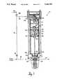
- FIG. 1shows the injection assembly of this invention.
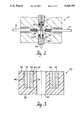
- FIG. 2is a cross-sectional view showing the seal in a liquid chromatography injection apparatus.
- FIG. 3is a detailed cross-sectional view of the seal of this invention.
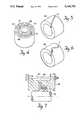
- FIG. 4is an isometric view of the seal assembly of FIG. 3.
- FIG. 5is an isometric view of a cylindrical band spring structure utilized in the present invention
- FIG. 6is an isometric view of an alternative cylindrical band structure utilized in the present invention.
- FIG. 7is a cross-sectional view of an alternative seal structure of this invention.
- the injection apparatus of this invention 10includes a conduit 12 extending from a pump (not shown) which supplies a carrier solvent into the injection apparatus 10 and, communicates with an outlet conduit 14 and thence to a chromatographic column (not shown).
- the liquidproceeds through a needle valving block 20 comprising an inlet port 22 and an outlet port 24 communicating with conduits 12 and 14, respectively.
- the sampling conduitcomprises a modified hypodermic needle 26 which includes an axial passageway 23 and a radial passageway 25 which communicates with outlet port 24.
- the hypodermic needle 26is adapted for reciprocating vertical movement within block 20.
- annular space 27is positioned adjacent the radial conduit 25 so that solvent passing through conduit 12 and inlet 22 can pass about the outside surface of the hypodermic needle 26 and entrain sample being injected from conduits 23 and 25 into outlet 24.
- a valve 16 in conduit 18is closed.
- liquid from the pumpwill flow through conduit 12 and also flow through conduit 18 and conduit 19 into extensible tubing 21 and thence through needle 26, to port 24, conduit 14 and to the chromatographic column (not shown).
- the connection means of needle 26 to piston 44is formed with nut 40 and ferrule 41.
- Piston 44can be pneumatically operated.
- the piston 44moves within a cylindrical housing 31 having a top housing plate 32 having a positioning nut 33 and a lower housing plate 34 which has a central channel 35 which continues into block 20 and within which needle 26 reciprocates.
- Air to raise the piston 44 and the needle 26enters conduit 46 and air to lower the piston 44 enters conduit 48.
- These air connectionsare connected to a Pneumatic control system (not shown).
- the piston 44is provided with lip seals 50 and 52. Travel of the piston 44 can be adjusted by modifying the vertical position of positioning nut 33.
- FIGS. 2 through 5the sealing structure of this invention is shown in detail. At positions just above and below annular space 27, it is necessary to provide an efficacious seal means capable of withstanding pressures of up to about 6,000 psig without binding the movement of needle 26 within bore 66.
- the apparatus of this inventionis intended to be utilized in analytical procedures wherein, routinely, samples as small as 5 microliters or smaller are processed.
- the chemical sensitivity of the analytical process being usedis such that most organic materials of construction can not be utilized because of chemical contamination which would be leached therefrom.
- the upper and lower seals 30comprise a jacket 62 having a U-shaped cross section 64 and a central bore 66 through which the needle 26 passes during use of the apparatus.
- U-shaped cross section slot 64Within U-shaped cross section slot 64 are positioned two springs comprising a cylindrical band 68 and a cylindrical band 70 each of which contains a slot 72 or 74 which extends through the thickness and along the entire axial length of the cylinder 68 or 70 as specifically shown in FIG. 5.
- the jacket 62can be formed of ultrahigh molecular weight polyethylene or reinforced fluorocarbon based materials such as those available under the trade designation RULON J by Dixon Corporation. The material forming the jacket should have a good tensile and compressive strength properties.
- the inner diameter of the spring 68should be slightly less than the inner axial surface diameter 78 of the jacket 62.
- the outer diameter of springs 70should be slightly larger than the diameter of the outer axial surface 80 of the U-shaped cross section 64.
- the diameter of the inner surface of the U-shaped slot 78typically is between about 0.087 and 0.001 inches larger than the inner diameter of the spring 68.
- the diameter of bore 66typically is between about 0.009 and 0.006 inches less than the outer diameter of the hypodermic needle inserted therein.
- the cylindrical band 69can have a slot 71 which is curved.
- FIG. 7An alternative seal structure is shown in FIG. 7. which includes only one cylindrical band as a spring.
- the seal structureincludes a clamp 96 which is compressed by means of bolt 87 about a ultrahigh molecular weight polyethylene jacket 89.
- the cylindrical band 91 of this inventionis positioned against jacket 89 to effect a seal about shaft 93 such as a shaft of a pump.
- seal structure of the present inventionis useful in any device wherein there is relative movement, rotational and/or translational, therein an element including the seal structure either moves or remains fixed.
Landscapes
- Engineering & Computer Science (AREA)
- General Engineering & Computer Science (AREA)
- Immunology (AREA)
- Pathology (AREA)
- Analytical Chemistry (AREA)
- Biochemistry (AREA)
- General Health & Medical Sciences (AREA)
- General Physics & Mathematics (AREA)
- Physics & Mathematics (AREA)
- Chemical & Material Sciences (AREA)
- Life Sciences & Earth Sciences (AREA)
- Health & Medical Sciences (AREA)
- Mechanical Engineering (AREA)
- Sampling And Sample Adjustment (AREA)
- Sealing Using Fluids, Sealing Without Contact, And Removal Of Oil (AREA)
- Infusion, Injection, And Reservoir Apparatuses (AREA)
Abstract
Description
Claims (2)
Priority Applications (5)
| Application Number | Priority Date | Filing Date | Title |
|---|---|---|---|
| US07/418,103US5146793A (en) | 1989-10-06 | 1989-10-06 | Fluid seal |
| EP90119166AEP0421463B1 (en) | 1989-10-06 | 1990-10-05 | Fluid seal |
| DE69027393TDE69027393T2 (en) | 1989-10-06 | 1990-10-05 | Fluid seal |
| JP2266554AJP2860151B2 (en) | 1989-10-06 | 1990-10-05 | Fluid seal structure |
| US07/661,782US5114161A (en) | 1989-10-06 | 1991-03-20 | Fluid seal |
Applications Claiming Priority (1)
| Application Number | Priority Date | Filing Date | Title |
|---|---|---|---|
| US07/418,103US5146793A (en) | 1989-10-06 | 1989-10-06 | Fluid seal |
Related Child Applications (1)
| Application Number | Title | Priority Date | Filing Date |
|---|---|---|---|
| US07/661,782DivisionUS5114161A (en) | 1989-10-06 | 1991-03-20 | Fluid seal |
Publications (1)
| Publication Number | Publication Date |
|---|---|
| US5146793Atrue US5146793A (en) | 1992-09-15 |
Family
ID=23656724
Family Applications (2)
| Application Number | Title | Priority Date | Filing Date |
|---|---|---|---|
| US07/418,103Expired - LifetimeUS5146793A (en) | 1989-10-06 | 1989-10-06 | Fluid seal |
| US07/661,782Expired - LifetimeUS5114161A (en) | 1989-10-06 | 1991-03-20 | Fluid seal |
Family Applications After (1)
| Application Number | Title | Priority Date | Filing Date |
|---|---|---|---|
| US07/661,782Expired - LifetimeUS5114161A (en) | 1989-10-06 | 1991-03-20 | Fluid seal |
Country Status (4)
| Country | Link |
|---|---|
| US (2) | US5146793A (en) |
| EP (1) | EP0421463B1 (en) |
| JP (1) | JP2860151B2 (en) |
| DE (1) | DE69027393T2 (en) |
Cited By (3)
| Publication number | Priority date | Publication date | Assignee | Title |
|---|---|---|---|---|
| EP0773442A1 (en)* | 1995-11-08 | 1997-05-14 | Tosoh Corporation | Piston with lubricating seal |
| US5757666A (en)* | 1993-04-23 | 1998-05-26 | Boehringer Mannheim Gmbh | System for analyzing compounds contained liquid samples |
| CN110261556A (en)* | 2018-03-12 | 2019-09-20 | 拉尔分析仪器有限公司 | Measuring device and method for determining constituent substances or quality parameters of water or waste water |
Families Citing this family (4)
| Publication number | Priority date | Publication date | Assignee | Title |
|---|---|---|---|---|
| US9075035B2 (en) | 2010-01-11 | 2015-07-07 | Waters Technologies Corporation | Injection port needle support and washing |
| WO2015003037A1 (en)* | 2013-07-03 | 2015-01-08 | Wyatt Technology Corporation | Method and apparatus to control sample carryover in analytical instruments |
| KR102576874B1 (en)* | 2019-06-11 | 2023-09-11 | 엔오케이 가부시키가이샤 | Sealing device and installation method of the sealing device |
| DE102019007195B4 (en)* | 2019-10-16 | 2025-03-27 | Maag Automatik Gmbh | System for sealing a fluid passage from a first component to a second component |
Citations (5)
| Publication number | Priority date | Publication date | Assignee | Title |
|---|---|---|---|---|
| US2211899A (en)* | 1938-03-12 | 1940-08-20 | Int Harvester Co | Seal |
| US3061320A (en)* | 1958-09-29 | 1962-10-30 | Aeroquip Gmbh | Axial seal for rotary shafts or the like |
| US4094196A (en)* | 1977-02-25 | 1978-06-13 | Waters Associates, Inc. | Sample injection with automatic cleaning of sampling conduit |
| US4526387A (en)* | 1983-01-28 | 1985-07-02 | Cross Manufacturing Company (1938) Limited | Rotatable shaft seals |
| US4739997A (en)* | 1986-09-05 | 1988-04-26 | Potlatch Corporation | Pressurized bearing seal assembly |
Family Cites Families (9)
| Publication number | Priority date | Publication date | Assignee | Title |
|---|---|---|---|---|
| CA644864A (en)* | 1962-07-17 | E. Estey Melvin | Valve stem seal | |
| DE69128C (en)* | O.FRANK in Berlin S.W., Johanniterstr. 9, I | Oil seal for closed axle bushes on railway vehicles | ||
| US1554153A (en)* | 1924-05-29 | 1925-09-15 | Williams Clarence Percy | Pump packing |
| US2877070A (en)* | 1956-03-30 | 1959-03-10 | Luther E Lee | Fluid pressure seal |
| AT304971B (en)* | 1968-08-02 | 1973-02-12 | Jenoe Szepesvary Dipl Ing | Seal designed as a radial or axial seal |
| US3861691A (en)* | 1971-12-16 | 1975-01-21 | Texacone Co | Packing member |
| US3889958A (en)* | 1974-04-15 | 1975-06-17 | Case Co J I | Piston rod floating wiper |
| ES273011Y (en)* | 1983-06-17 | 1984-07-16 | Castano Martin Jose M | "SEALING DEVICE FOR VALVES" |
| DE3616689C1 (en)* | 1986-05-16 | 1987-11-19 | Mueller Heinz Konrad Prof Dr I | poetry |
- 1989
- 1989-10-06USUS07/418,103patent/US5146793A/ennot_activeExpired - Lifetime
- 1990
- 1990-10-05EPEP90119166Apatent/EP0421463B1/ennot_activeExpired - Lifetime
- 1990-10-05JPJP2266554Apatent/JP2860151B2/ennot_activeExpired - Lifetime
- 1990-10-05DEDE69027393Tpatent/DE69027393T2/ennot_activeExpired - Lifetime
- 1991
- 1991-03-20USUS07/661,782patent/US5114161A/ennot_activeExpired - Lifetime
Patent Citations (5)
| Publication number | Priority date | Publication date | Assignee | Title |
|---|---|---|---|---|
| US2211899A (en)* | 1938-03-12 | 1940-08-20 | Int Harvester Co | Seal |
| US3061320A (en)* | 1958-09-29 | 1962-10-30 | Aeroquip Gmbh | Axial seal for rotary shafts or the like |
| US4094196A (en)* | 1977-02-25 | 1978-06-13 | Waters Associates, Inc. | Sample injection with automatic cleaning of sampling conduit |
| US4526387A (en)* | 1983-01-28 | 1985-07-02 | Cross Manufacturing Company (1938) Limited | Rotatable shaft seals |
| US4739997A (en)* | 1986-09-05 | 1988-04-26 | Potlatch Corporation | Pressurized bearing seal assembly |
Cited By (3)
| Publication number | Priority date | Publication date | Assignee | Title |
|---|---|---|---|---|
| US5757666A (en)* | 1993-04-23 | 1998-05-26 | Boehringer Mannheim Gmbh | System for analyzing compounds contained liquid samples |
| EP0773442A1 (en)* | 1995-11-08 | 1997-05-14 | Tosoh Corporation | Piston with lubricating seal |
| CN110261556A (en)* | 2018-03-12 | 2019-09-20 | 拉尔分析仪器有限公司 | Measuring device and method for determining constituent substances or quality parameters of water or waste water |
Also Published As
| Publication number | Publication date |
|---|---|
| JP2860151B2 (en) | 1999-02-24 |
| JPH03199962A (en) | 1991-08-30 |
| EP0421463B1 (en) | 1996-06-12 |
| EP0421463A3 (en) | 1992-09-02 |
| DE69027393T2 (en) | 1996-11-07 |
| DE69027393D1 (en) | 1996-07-18 |
| EP0421463A2 (en) | 1991-04-10 |
| US5114161A (en) | 1992-05-19 |
Similar Documents
| Publication | Publication Date | Title |
|---|---|---|
| US4094196A (en) | Sample injection with automatic cleaning of sampling conduit | |
| CA1097101A (en) | Seal and apparatus including same | |
| US5601708A (en) | Apparatus for pressurizing a removable chromatography cartridge | |
| US4187177A (en) | Column for high pressure liquid chromatography | |
| US4621534A (en) | Automatic sample apparatus, valve and sampling method | |
| US3951167A (en) | Fluid handling assembly | |
| US5146793A (en) | Fluid seal | |
| US6802968B2 (en) | Chromatography apparatus | |
| US9075035B2 (en) | Injection port needle support and washing | |
| JPH023789A (en) | One-way check valve for pressure fluid | |
| US6684720B2 (en) | Autosampler syringe with compression sealing | |
| US5486289A (en) | System for mechanically stabilizing a bed of particulate media | |
| US4440032A (en) | Sampler incorporating a purge system | |
| US4620452A (en) | Liquid sample injecting apparatus | |
| GB2290283A (en) | Rotary injection valve | |
| US3948104A (en) | Automatic rotary sample injection valve | |
| EP0032560B1 (en) | Direct on-column injector and injection method | |
| US5277073A (en) | Constant pressure-loaded shaft seal | |
| ATE329259T1 (en) | AUTOCLAVEABLE ANNULAR CHROMATOGRAPH | |
| US20250052729A1 (en) | Biocompatible fitting assembly and fluidic connection system | |
| JP2022503693A (en) | Chromatographic column with dual purpose valve assembly | |
| US6281019B1 (en) | Device for non-pulsating post-column derivatization | |
| US20090126467A1 (en) | Washing device for liquid chromatography injectors | |
| GB2494681A (en) | A low compressibility and high tightness, high performance piston seal | |
| JPS6086465A (en) | Automatic sampling equipment, valves and sampling methods |
Legal Events
| Date | Code | Title | Description |
|---|---|---|---|
| AS | Assignment | Owner name:MILLIPORE CORPORATION, MASSACHUSETTS Free format text:ASSIGNMENT OF ASSIGNORS INTEREST.;ASSIGNORS:SGOURAKES, GEORGE E.;KOZIOL, STANISLAW;REEL/FRAME:005183/0788 Effective date:19891102 | |
| STCF | Information on status: patent grant | Free format text:PATENTED CASE | |
| AS | Assignment | Owner name:WATERS INVESTMENTS LIMITED, DELAWARE Free format text:ASSIGNMENT OF ASSIGNORS INTEREST;ASSIGNOR:MILLIPORE CORPORATION;REEL/FRAME:006894/0038 Effective date:19931214 | |
| AS | Assignment | Owner name:BANKERS TRUST COMPANY, NEW YORK Free format text:SECURITY INTEREST;ASSIGNOR:WATERS INVESTMENTS LIMITED;REEL/FRAME:007145/0452 Effective date:19940818 | |
| FEPP | Fee payment procedure | Free format text:PAYOR NUMBER ASSIGNED (ORIGINAL EVENT CODE: ASPN); ENTITY STATUS OF PATENT OWNER: LARGE ENTITY | |
| AS | Assignment | Owner name:BANKERS TRUST COMPANY, NEW YORK Free format text:SECURITY INTEREST;ASSIGNOR:WATERS INVESTMENTS LIMITED;REEL/FRAME:007986/0191 Effective date:19951122 | |
| FPAY | Fee payment | Year of fee payment:4 | |
| AS | Assignment | Owner name:WATERS INVESTMENT LIMITED, DELAWARE Free format text:PATENT RELEASE;ASSIGNOR:BANKERS TRUST COMPANY;REEL/FRAME:008077/0511 Effective date:19951122 | |
| FPAY | Fee payment | Year of fee payment:8 | |
| AS | Assignment | Owner name:WATERS INVESTMENTS LIMITED, DELAWARE Free format text:RELEASE OF SECURITY INTEREST IN PATENTS;ASSIGNOR:BANKERS TRUST COMPANY, AS COLLATERAL AGENT;REEL/FRAME:012822/0456 Effective date:20020211 | |
| FPAY | Fee payment | Year of fee payment:12 | |
| AS | Assignment | Owner name:WATERS TECHNOLOGIES CORPORATION, MASSACHUSETTS Free format text:MERGER;ASSIGNOR:WATERS INVESTMENTS LIMITED;REEL/FRAME:022552/0606 Effective date:20081117 |