US5146713A - Hydraulic door operating system for autoclaves and sterilizers - Google Patents
Hydraulic door operating system for autoclaves and sterilizersDownload PDFInfo
- Publication number
- US5146713A US5146713AUS07/695,051US69505191AUS5146713AUS 5146713 AUS5146713 AUS 5146713AUS 69505191 AUS69505191 AUS 69505191AUS 5146713 AUS5146713 AUS 5146713A
- Authority
- US
- United States
- Prior art keywords
- door
- chamber
- clamping
- hydraulic pressure
- force
- Prior art date
- Legal status (The legal status is an assumption and is not a legal conclusion. Google has not performed a legal analysis and makes no representation as to the accuracy of the status listed.)
- Expired - Lifetime
Links
- 238000007789sealingMethods0.000claimsabstractdescription59
- 238000000034methodMethods0.000claimsabstractdescription11
- 230000007246mechanismEffects0.000abstractdescription6
- 239000012530fluidSubstances0.000description9
- 230000007935neutral effectEffects0.000description7
- 230000001954sterilising effectEffects0.000description3
- 238000004659sterilization and disinfectionMethods0.000description3
- 230000003213activating effectEffects0.000description2
- 238000010586diagramMethods0.000description2
- 230000000266injurious effectEffects0.000description2
- 239000007788liquidSubstances0.000description2
- 239000000565sealantSubstances0.000description2
- 208000027418Wounds and injuryDiseases0.000description1
- 230000009471actionEffects0.000description1
- 230000000712assemblyEffects0.000description1
- 238000000429assemblyMethods0.000description1
- 230000008901benefitEffects0.000description1
- 230000008859changeEffects0.000description1
- 230000006378damageEffects0.000description1
- 238000006073displacement reactionMethods0.000description1
- 230000000694effectsEffects0.000description1
- 208000015181infectious diseaseDiseases0.000description1
- 208000014674injuryDiseases0.000description1
- 238000012986modificationMethods0.000description1
- 230000004048modificationEffects0.000description1
- 238000012544monitoring processMethods0.000description1
Images


Classifications
- E—FIXED CONSTRUCTIONS
- E05—LOCKS; KEYS; WINDOW OR DOOR FITTINGS; SAFES
- E05F—DEVICES FOR MOVING WINGS INTO OPEN OR CLOSED POSITION; CHECKS FOR WINGS; WING FITTINGS NOT OTHERWISE PROVIDED FOR, CONCERNED WITH THE FUNCTIONING OF THE WING
- E05F7/00—Accessories for wings not provided for in other groups of this subclass
- E05F7/02—Accessories for wings not provided for in other groups of this subclass for raising wings before being turned
- A—HUMAN NECESSITIES
- A61—MEDICAL OR VETERINARY SCIENCE; HYGIENE
- A61L—METHODS OR APPARATUS FOR STERILISING MATERIALS OR OBJECTS IN GENERAL; DISINFECTION, STERILISATION OR DEODORISATION OF AIR; CHEMICAL ASPECTS OF BANDAGES, DRESSINGS, ABSORBENT PADS OR SURGICAL ARTICLES; MATERIALS FOR BANDAGES, DRESSINGS, ABSORBENT PADS OR SURGICAL ARTICLES
- A61L2/00—Methods or apparatus for disinfecting or sterilising materials or objects other than foodstuffs or contact lenses; Accessories therefor
- A61L2/26—Accessories or devices or components used for biocidal treatment
- B—PERFORMING OPERATIONS; TRANSPORTING
- B01—PHYSICAL OR CHEMICAL PROCESSES OR APPARATUS IN GENERAL
- B01J—CHEMICAL OR PHYSICAL PROCESSES, e.g. CATALYSIS OR COLLOID CHEMISTRY; THEIR RELEVANT APPARATUS
- B01J3/00—Processes of utilising sub-atmospheric or super-atmospheric pressure to effect chemical or physical change of matter; Apparatus therefor
- B01J3/03—Pressure vessels, or vacuum vessels, having closure members or seals specially adapted therefor
- E—FIXED CONSTRUCTIONS
- E05—LOCKS; KEYS; WINDOW OR DOOR FITTINGS; SAFES
- E05F—DEVICES FOR MOVING WINGS INTO OPEN OR CLOSED POSITION; CHECKS FOR WINGS; WING FITTINGS NOT OTHERWISE PROVIDED FOR, CONCERNED WITH THE FUNCTIONING OF THE WING
- E05F15/00—Power-operated mechanisms for wings
- E05F15/50—Power-operated mechanisms for wings using fluid-pressure actuators
- E—FIXED CONSTRUCTIONS
- E05—LOCKS; KEYS; WINDOW OR DOOR FITTINGS; SAFES
- E05Y—INDEXING SCHEME ASSOCIATED WITH SUBCLASSES E05D AND E05F, RELATING TO CONSTRUCTION ELEMENTS, ELECTRIC CONTROL, POWER SUPPLY, POWER SIGNAL OR TRANSMISSION, USER INTERFACES, MOUNTING OR COUPLING, DETAILS, ACCESSORIES, AUXILIARY OPERATIONS NOT OTHERWISE PROVIDED FOR, APPLICATION THEREOF
- E05Y2900/00—Application of doors, windows, wings or fittings thereof
- E—FIXED CONSTRUCTIONS
- E05—LOCKS; KEYS; WINDOW OR DOOR FITTINGS; SAFES
- E05Y—INDEXING SCHEME ASSOCIATED WITH SUBCLASSES E05D AND E05F, RELATING TO CONSTRUCTION ELEMENTS, ELECTRIC CONTROL, POWER SUPPLY, POWER SIGNAL OR TRANSMISSION, USER INTERFACES, MOUNTING OR COUPLING, DETAILS, ACCESSORIES, AUXILIARY OPERATIONS NOT OTHERWISE PROVIDED FOR, APPLICATION THEREOF
- E05Y2999/00—Subject-matter not otherwise provided for in this subclass
Definitions
- the inventionrelates to closure systems and methods for releasably sealing autoclaves and sterilizers. More particularly, the invention relates to a variable pressure, hydraulically actuated door clamping system for an autoclave or sterilizer door which is also self-locking. In addition, the invention relates to a variable pressure, hydraulically actuated system for positioning the autoclave door between open and closed positions and also vertically positioning the door so that the clamping system is engaged.
- the autoclave and sterilizer artgenerally describes apparatus and methods for releasably sealing doors of autoclaves and sterilizers.
- the ability of a particular apparatus to effectively seal a sterilizeris critical because the apparatus must maintain the temperature and pressure environment within the sterilizer to insure that effective sterilization takes place. Ineffective sterilization may result in contaminated equipment or articles which are subsequently used for medical procedures. The contaminated equipment or articles may in turn cause infection in patients.
- autoclave or sterilizer sealing apparatusmust be operable in a safe manner by the person using the apparatus.
- U.S. Pat. No. 4,932,160describes an apparatus for sealing an autoclave door which includes both the use of a compressible gasket and a pressurized fluid.
- the compressible gasketis located in a gasket channel, and once the autoclave door is moved to a closed position the pressurized fluid is pumped into the gasket channel and forces the compressible gasket against the door to provide an effective seal.
- Other patentsteach similar sealing apparatus which rely on the use of a pressurized fluid to provide an effective seal between the door and chamber of an autoclave or sterilizer. For example, U.S. Pat. Nos.
- the present inventionprovides an apparatus and method which is useful for opening, closing, and sealing an autoclave or sterilizer door.
- the present inventionovercomes the disadvantages of conventional autoclave sealing systems which use compressible gaskets.
- the present inventionis capable of adjusting to creep or permanent set in the gasket. Conventional sealing systems without this capability tend to lose the effectiveness of their seal.
- the present inventionovercomes the disadvantages of conventional autoclave and sterilizer sealing systems which relate to the loss of electrical or hydraulic power.
- the present inventionprovides a self-locking sealing system which cannot be unsealed without the application of positive hydraulic pressure. This insures that the apparatus of the present invention will maintain its seal when electrical or hydraulic power is lost.
- the present inventionprovides mechanisms for manually generating hydraulic pressure and activating the clamping system, the door opening and closing system, and the door raising and lowering system. Consequently, the apparatus of the present invention can be completely manually operated during any loss of electrical or hydraulic power.
- the present inventiongenerally comprises an apparatus for opening, closing and sealing a door of a chamber.
- the apparatuscomprises a means for clamping the door to the chamber to provide an effective seal therebetween.
- the clamping meansis capable of providing a variable force for clamping the door to the chamber.
- a compressible gasketis provided between the door and the chamber to effect the seal therebetween.
- the clamping meanscomprises a plurality of extendable hydraulically driven pins which exert a mechanical force on lugs along the edge of the door towards a sealing face of the chamber and thereby compresses the gasket to provide an effective seal.
- the hydraulically driven pinsare designed so that a positive hydraulic pressure is required to extend or retract the pins.
- the hydraulically driven pinsmay be described as self-locking because once in an extended position, even if hydraulic pressure to the pin is lost, the pin cannot be retracted without the application of hydraulic pressure.
- the apparatusalso comprises a means for moving the door between an open position which allows loading of equipment and carts into the chamber and a closed position in which the door is positioned against the face of the chamber.
- the means for moving the door between the open and closed positionsincludes the capability of varying the force used to move the door between the open and closed positions.
- a hydraulic cylinderis used to move the door between the open and closed positions, and the hydraulic pressure fed to the hydraulic cylinder can be varied as desired to vary the force exerted in opening and closing the door.
- the apparatuscomprises means for raising or lowering the door to engage the clamping means.
- the raising and lowering meansis preferably capable of providing variable force for raising and lowering the door.
- the raising and lowering meanspreferably comprises a hydraulic cylinder wherein the force exerted by the hydraulic cylinder is adjustable to vary the force used to raise or lower the door.
- the apparatusadditionally comprises a guiding means for guiding the door as it is lowered so that it effectively engages the hydraulically driven pins of the clamping means.
- the guiding meanseliminates problems associated with the door getting hung up on the pins of the clamping means.
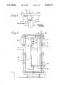
- FIG. 1is a perspective view of the apparatus of the present invention wherein the autoclave door is opened to the left;
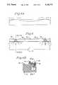
- FIG. 4is a cross-sectional view of a portion of the door showing the gasket retaining bar, and depicting a force to distance diagram between that portion of the door and the gasket retaining bar;
- FIG. 5is a schematic view of the hydraulic circuit used for controlling the clamping means, open-close cylinder, and raise-lower cylinder.
- FIG. 1an overall perspective view of the apparatus for opening, closing, and sealing a door of an autoclave or sterilizer is depicted.
- An autoclave or sterilizer chamber 10 and corresponding door 12 along with assemblies for opening, closing, and sealing the door 12 against the sealing face 16 of the chamber 10are shown.
- the door 12is pivotally mounted on the sealing face 16 by two hinges 14, 15. As shown in FIG. 1, the door 12 will open to the left because the hinges attach the door to the chamber on the left. It should be appreciated that the door could be opened to the right by attaching the door to the sealing face of the chamber using hinges on the right.
- An open-close assemblyis used to move the door 12 between an open position which allows access for loading the chamber 10 with carts and equipment to be sterilized and a closed position in which the door 12 is positioned against the sealing face 16.
- the open-close assemblyincludes an open-close hydraulic cylinder 18, a chamber pivot connector 20, and a door connector 22. Any conventionally available hydraulic cylinder with an extendable rod which will extend and retract by application of hydraulic pressure to the cylinder may be used as the open-close hydraulic cylinder 18. The amount of force exerted by the rod as it extends and retracts is proportional to the amount of hydraulic pressure supplied to the cylinder. In addition, the rod of the hydraulic cylinder must exert sufficient force to move the door.
- One end of the open-close hydraulic cylinder 18is pivotally attached to the chamber pivot connector 20 which is in turn attached to the top of the chamber 10.
- the open-close hydraulic cylinder 18is oriented parallel to the top of the chamber 10 and pivots through a range of positions which are parallel to the top of the chamber 10.
- the end of the open-close hydraulic cylinder 18 which is distal to the chamber pivot connector 20is pivotally attached to door connector 22.
- Connector 22is in turn attached to a hinge member 24 which is attached to the sealing face 16 of the chamber 10 by hinge 15.
- a door frame assemblyis used to connect the door 12 to the sealing face 16 by way of hinges 14 and 15.
- the door frame assemblyincludes two hinge members 24 and 25 which connect to hinges 14 and 15 and extend horizontally across the face of the door; and two vertical members 26 and 27 which vertically interconnect hinge members 24 and 25.
- the door frame assemblyfurther includes a raise-lower hydraulic cylinder 30 and a cross member 28 between vertical members 26 and 27 for supporting the raise-lower hydraulic cylinder 30.
- the door 12includes bars 34 and 40 which are located horizontally at the top and the bottom of the door 12 and extend outwards from the face of the door 12.
- a rod 37is attached at one end to bar 40.
- Rod 37extends vertically from the bar 40 through a hole in hinge member 25 and through a guiding plate 38. In this manner the rod 37 may slide through the hole of hinge member 25 and guiding plate 38.
- the raise-lower hydraulic cylinder 30includes a rod 32 which extends through a guiding plate 36 and through a hole in the hinge member 24 and connects to the bar 34. In this manner the rod 32 can slide through the hinge member 24 and guiding plate 36. Guiding plates 36 and 38 are welded to the door 12.
- any conventionally available hydraulic cylinder with an extendable rod which will extend and retract by application of hydraulic pressure to the cylindermay be used as the raise-lower hydraulic cylinder 30.
- the amount of force exerted by the rod as it extends and retractsis proportional to the amount of hydraulic pressure supplied to the cylinder. Further, the rod of the hydraulic cylinder must exert sufficient force to raise the door 12.
- the raise-lower assembly and door frame assemblyallow the door 12 to be raised and lowered through a range of positions relative to the sealing face 16 by application of hydraulic pressure to the raise-lower hydraulic cylinder 30.
- the maximum amount of vertical displacement when the door 12 is raised or loweredis determined by limit switches for the hydraulic circuit which operates the raise-lower cylinder rod 32.
- the doorfurther includes lugs 42 which are used to apply mechanical pressure to the door 12 to seal it against the sealing face 16 of the chamber 10.
- the clamping means for applying mechanical pressure to lugs 42are not shown in FIG. 1 but are described below.
- the door 12includes a compressible gasket 44 and a gasket retaining bar 46 which run continuously around the inside edge of the door 12.
- the compressible gasket 44is parabolic shaped with a lip such that the flat side of the gasket 44 and the lip are positioned against the inside face of the door 12 and the curved side of the gasket 44 faces the sealing face 16.
- the gasket retaining bar 46is attached to the door and includes a rib which extends over the lip of the gasket 44 and interlocks with the gasket 44. In this manner, the gasket 44 is maintained in position against the inside face of the door 12.
- the clamping meansincludes multiple clamps 48 which are attached to sealing face 16.
- Each clamp 48includes an extendable hydraulically driven pin 52 which contacts a door lug 42 on the door 12. When hydraulic pressure is applied to the clamp 48, it provides mechanical force to extend the pin 52 which in turn compresses the gasket 44 against the sealing face 16. The mechanical force exerted by the pin 52 against the door lug 42 is proportional to the amount of hydraulic pressure supplied to the clamp 48.
- Each clamp 48includes a ramp 50 which is located adjacent to and vertically above the pin 52 of the clamp 48. The ramp 50 serves to align and move the door 12 against the sealing face 16 as the door 12 is vertically lowered so that the lugs 42 will engage the pins 52.
- the clamps as described hereinare self-locking hydraulic clamping devices as described in Reissue U.S. Pat. No. 32,704, incorporated herein by reference.
- This patentis a reissue of U.S. Pat. No. 4,511,127).
- the clamping devices described in these patentshave the advantage of being self-locking such that even if hydraulic pressure fails the clamps will maintain their locked and clamped status.
- the self-locking clamps of these patentsuse a minimum amount of space.
- the door 12additionally includes "Vlier" pins which provide a pressure to displace the door a small amount from the sealing face 16 of the sterilizer. Once the door is unclamped, the force exerted by the "Vlier" pins pushes the door 12 away from the sealing face 16 thereby breaking the seal.
- FIG. 3a front view of a door in a closed and lowered position relative to a chamber is shown.
- the chamberis located in a pit but is supported above the bottom surface of the pit by support members 54.
- I-beamsmay be used for this purpose.
- Sealing face 16includes ten clamps 48 of the type disclosed in Reissue U.S. Pat. No. 32,704. Five of the clamps 48 are located on the left side of the sealing face 16, and the other five clamps 48 are located on the right side of the sealing face 16. Corresponding to the ten clamps 48 are ten lugs 42.
- the lugs 42are located between the clamps 48 and the sealing face 16. Consequently, when the clamps 48 are hydraulically actuated, the pins of the clamps 48 apply mechanical pressure to force the door 12 against the sealing face 16 such that the gasket 44 is compressed between the door 12 and the sealing face 16.
- the door 12cannot be pivotally moved to an open position because the clamps 48 prevent the door from opening.
- the bottom edge of the door 12is located below the top edge of the pit.
- the top edge of the pitwill prevent the door 12 from opening.
- the lugs 42are clear of the clamps 48 and the bottom edge of the door is above the top edge of the pit. The door can then be moved to an open position. It is desirable to locate the chamber in a pit so that equipment on wheeled trays can easily be rolled directly into the chamber without a change in elevation.
- FIG. 4a cross-sectional view of the gasket retaining bar 46 as attached to the door 12 is shown.
- the gasket retaining bar 46is attached to the inside face of the door 12 with multiple bolts 56. It should be appreciated that the amount of clamping force along the gasket retaining bar 46 depends on the proximity of that part of the gasket retaining bar 46 to a bolt 56.
- FIG. 4includes a diagram of the relationship between the clamping force and the distance along the gasket retaining bar 46 between the bolts used to secure the gasket retaining bar 46 to the door 12.
- a sealant liquidsuch as Permatex Aviation's Form-a-Gasket is spread in about a one inch thick margin along the edge of the inner face of the door 12 as indicated by the dimension " X" in FIG. 4.
- FIG. 5depicts the hydraulic circuit which is used to control the clamping means, the open-close hydraulic cylinder, and the raise-lower hydraulic cylinder.
- the hydraulic circuit for the present inventiongenerally includes three subcircuits, one each for the clamping means, the open-close hydraulic cylinder, and the raise-lower hydraulic cylinder. Each of these subcircuits is commonly provided with hydraulic pressure by a pump 66 driven by a motor 62 which provides hydraulic pressure to the overall circuit and each of the subcircuits.
- the pumpincludes a check valve 66 at its discharge and a pressure valve 68 for monitoring the pressure in the hydraulic circuit.
- a controller 70is provided to regulate the overall pressure in the hydraulic circuit.
- the controller 70is manually set to achieve a desired pressure in the overall hydraulic circuit.
- a manual hydraulic pressuring device 72is also provided in the overall circuit to provide hydraulic pressure should electrical power fail.
- Hydraulic pressureis provided to the clamps 48 via a solenoid valve 74.
- solenoid valve 74When solenoid valve 74 is set in the left actuated position, hydraulic pressure from the overall circuit is provided to the clamping mechanism of the clamps 48 and causes the clamp pins to extend and seal the door against the chamber.
- the solenoid valve 74When it is desired to unseal the door from the chamber, the solenoid valve 74 is set in the right actuated position which provides hydraulic pressure to the release mechanism of the clamps 48 and causes the clamp pins to retract. It should be appreciated that the positive application of hydraulic pressure is required to move the clamp pins from either the clamped or unclamped positions. In the absence of positive hydraulic pressure, the clamp pins will remain in the state that they were most recently placed in.
- the solenoid valve 74When not being used to open or close the clamping means, the solenoid valve 74 is set in a neutral position. If it is desired to increase the amount of pressure provided by the clamps to offset set or creep in the door gasket, the controller 70 may be adjusted to increase the overall pressure in the hydraulic circuit. The clamps 48 will then provide correspondingly increased pressure to seal the door to the chamber.
- the clamps 48can be operated during the failure of electrical power or failure of the pump 64 because the solenoid valve 74 has a float center which permits operation of the solenoid valve 74 when it is unpowered and hydraulic pressure can be applied through solenoid valve 74 by the manual hydraulic pressure device 72. In this manner, the clamps 48 can always be clamped or unclamped during losses of electrical power or failure of the pump 64.
- Hydraulic pressureis supplied to the open-close hydraulic subcircuit by controller 76 and a solenoid valve 78.
- the controller 76is used to set the pressure in the open-close hydraulic subcircuit at a desired level which may be different than the pressure in the overall hydraulic circuit.
- solenoid valve 78When solenoid valve 78 is set in the left actuated position, hydraulic pressure causes the open-close hydraulic cylinder 18 to extend which in turn causes the door to open. After the door 12 is opened, the solenoid valve 78 is set in a neutral position.
- the amount of force which is used to open the doormay be adjusted using variable pressure reducing valve 80 in the open-close hydraulic subcircuit. By adjusting the opening force to a desired amount, it can be insured that the opening torque of the door is non-injurious.
- the solenoid valve 78When it is desired to close the door, the solenoid valve 78 is set to the right actuated position which provides hydraulic pressure to the open-close hydraulic cylinder 18 such that the cylinder is contracted. As in the case of opening the door, the closing force of the door may be adjusted by variable pressure reducing valve 82 to insure that a non-injurious closing torque is used. Typically, the variable pressure reducing valves 80 and 82 will be set such that a resistance caused by a person's arm inserted between the door and chamber will overcome the closing or opening pressure.
- the open-close hydraulic subcircuitadditionally includes check valves 81 and 83. Check valves 81 and 83 provide protection against inadvertent opening or closing of the door over time by insuring that hydraulic pressure is not lost in the open-close hydraulic subcircuit due to leakage or gradual loss of pressure in the overall hydraulic circuit.
- the hydraulic subcircuit for the raise-lower cylinder 30is supplied with hydraulic pressure from the overall hydraulic circuit via controller 84 and solenoid valve 86.
- Controller 84maintains the pressure of the raise-lower hydraulic subcircuit at a desired level which may be different from the pressure in the overall hydraulic circuit.
- Solenoid valve 86is used to actuate the raise-lower hydraulic cylinder 30. When solenoid valve 86 is set in the right actuated position, hydraulic pressure is supplied to the raise-lower hydraulic cylinder 30 and causes the cylinder 30 to extend thereby raising the door. After the door is raised, the solenoid valve 86 is set to a neutral position. The amount of force used to raise the door is controlled by the variable flow control valve 88.
- variable flow control valve 90As in the case of the open-close hydraulic subcircuit a check valve 91 has been included in the raise-lower hydraulic subcircuit to prevent inadvertent lowering of the door over time due to leakage from the overall hydraulic circuit.
- the doorWhen the door is in an open position, carts loaded with medical equipment are loaded into the sterilizer chamber as desired.
- the dooris then closed by activating the pump of the overall hydraulic circuit and setting the solenoid valve for the open-close hydraulic subcircuit in a left actuated position.
- the open-close solenoid valvecauses hydraulic pressure to be supplied to the open-close hydraulic cylinder which in turn causes the cylinder to contract and close the door against the face of the sterilizer chamber.
- the reducing pressure valve of the closing part of the open-close hydraulic subcircuitshould be set such that minimal force is applied in closing the door. Minimal force in this context means that the force exerted on the door if it encounters a person's arm or other article will overcome the force provided to close the door by the open-close hydraulic cylinder.
- the dooris lowered into engagement with the clamps. This is accomplished by setting the raise-lower solenoid valve in the right actuated position which in turn supplies hydraulic pressure to the raise-lower hydraulic cylinder and causes it to contract. As the door is lowered, the ramps positioned adjacent to and above the pins of the clamps guide the door into proper position so that the door lugs are aligned with the clamps. The raise-lower solenoid valve is then set in a neutral position. The rate at which the door is lowered can be controlled by the variable flow control valve in the raise-lower hydraulic subcircuit.
- the doormay be sealed. This is accomplished by setting the clamp solenoid valve in a right actuated position which supplies hydraulic pressure to the clamps and causes the pins of the clamps to extend against the door lugs and press the door against the sealing face of the sterilizer. This in turn compresses the compressible gasket on the inside face of the door against the sealing face of the sterilizer and thereby provides an airtight seal between the interior of the sterilizer and the external atmosphere.
- the clamp solenoid valveis then set in a neutral position. If the compressible gasket has suffered from creep or permanent set, the pressure used to compress the compressible gasket between the door and sealing face of the sterilizer can be increased by increasing the pressure setting on the controller for the overall hydraulic circuit.
- the sterilizeris then cycled in its normal manner to sterilize the equipment which was loaded into the sterilizer.
- the sterilizeris unsealed by setting the clamp solenoid valve in the left actuated position. This causes hydraulic pressure from the overall hydraulic circuit to be supplied to the clamps such that the clamp pins are retracted and the pressure compressing the compressible gasket between the door and the sealing face of the sterilizer is released.
- the dooris further unsealed by the action of spring pins which are located around the edge of the door and causes the door to displace slightly away from the sealing face of the sterilizer.
- the door of the sterilizeris then raised by setting the raise-lower solenoid valve in the left actuated position. This in turn supplies hydraulic pressure to the raise-lower hydraulic cylinder such that the hydraulic cylinder extends and raises the door.
- the raise-lower solenoid valveis then returned to the neutral position. The force and rate at which the door is raised can be adjusted by the flow control valve for the raise portion of the raise-lower hydraulic subcircuit.
- the dooris then opened by setting the open-close solenoid valve in the left actuated position. This causes hydraulic pressure to be supplied to the open-close hydraulic cylinder such that it extends and causes the door to open.
- the open-close solenoid valveis then returned to its neutral position.
- the force exerted for opening the door by the open-close hydraulic cylinderis set at a minimal level by adjusting the pressure reducing valve for the open portion of the open-close hydraulic subcircuit.
- minimal forceas used in this context is the same as was described for the closing procedure for the door of the sterilizer.
- the opening, closing, and sealing apparatus of the inventioncan be adapted for use in autoclaves, sterilizers, or any other chamber in which it is desired to maintain an effective seal between the chamber and the external atmosphere.
Landscapes
- Health & Medical Sciences (AREA)
- Chemical & Material Sciences (AREA)
- Epidemiology (AREA)
- Life Sciences & Earth Sciences (AREA)
- Animal Behavior & Ethology (AREA)
- General Health & Medical Sciences (AREA)
- Public Health (AREA)
- Veterinary Medicine (AREA)
- Organic Chemistry (AREA)
- Chemical Kinetics & Catalysis (AREA)
- Apparatus For Disinfection Or Sterilisation (AREA)
Abstract
Description
Claims (23)
Priority Applications (1)
| Application Number | Priority Date | Filing Date | Title |
|---|---|---|---|
| US07/695,051US5146713A (en) | 1991-05-02 | 1991-05-02 | Hydraulic door operating system for autoclaves and sterilizers |
Applications Claiming Priority (1)
| Application Number | Priority Date | Filing Date | Title |
|---|---|---|---|
| US07/695,051US5146713A (en) | 1991-05-02 | 1991-05-02 | Hydraulic door operating system for autoclaves and sterilizers |
Publications (1)
| Publication Number | Publication Date |
|---|---|
| US5146713Atrue US5146713A (en) | 1992-09-15 |
Family
ID=24791357
Family Applications (1)
| Application Number | Title | Priority Date | Filing Date |
|---|---|---|---|
| US07/695,051Expired - LifetimeUS5146713A (en) | 1991-05-02 | 1991-05-02 | Hydraulic door operating system for autoclaves and sterilizers |
Country Status (1)
| Country | Link |
|---|---|
| US (1) | US5146713A (en) |
Cited By (41)
| Publication number | Priority date | Publication date | Assignee | Title |
|---|---|---|---|---|
| US6264901B1 (en) | 1998-11-03 | 2001-07-24 | Steris Corporation | Space frame sterilizer door |
| US20040093801A1 (en)* | 2002-11-15 | 2004-05-20 | Steris Inc. | Door assembly for sealing a chamber |
| US20040265167A1 (en)* | 2003-06-30 | 2004-12-30 | Todd Morrison | Sterilization vacuum chamber door closure |
| US20040267132A1 (en)* | 2003-06-30 | 2004-12-30 | Ethicon, Inc. | Ultrasonic radial focused transducer for pulmonary vein ablation |
| WO2004105932A3 (en)* | 2003-05-28 | 2005-02-17 | Rodwell Engineering Group Ltd | An autoclave |
| US20050134083A1 (en)* | 2003-12-23 | 2005-06-23 | Haibo Tong | Lock mechanism for a rotary door operator |
| US20060195064A1 (en)* | 2005-02-28 | 2006-08-31 | Fresenius Medical Care Holdings, Inc. | Portable apparatus for peritoneal dialysis therapy |
| US20080097283A1 (en)* | 2006-08-31 | 2008-04-24 | Plahey Kulwinder S | Data communication system for peritoneal dialysis machine |
| US20080125693A1 (en)* | 2006-08-31 | 2008-05-29 | Gavin David A | Peritoneal dialysis systems and related methods |
| US20080267817A1 (en)* | 2007-04-30 | 2008-10-30 | Midmark Corporation | Water management system for sterilizer |
| US20080296226A1 (en)* | 2007-05-29 | 2008-12-04 | Fresenius Medical Care Holdings, Inc. | Solutions, Dialysates, and Related Methods |
| USD598564S1 (en) | 2008-04-30 | 2009-08-18 | Midmark Corporation | Handle for portable sterilizing apparatus |
| USD598565S1 (en) | 2008-04-30 | 2009-08-18 | Midmark Corporation | External condensation tank for a sterilizer |
| USD603053S1 (en) | 2008-04-30 | 2009-10-27 | Midmark Corporation | Portable sterilizing apparatus |
| US20110040242A1 (en)* | 2009-08-11 | 2011-02-17 | Joseph Michael Fallon | Portable peritoneal dialysis carts and related systems |
| US7892197B2 (en) | 2007-09-19 | 2011-02-22 | Fresenius Medical Care Holdings, Inc. | Automatic prime of an extracorporeal blood circuit |
| US20110061185A1 (en)* | 2009-09-14 | 2011-03-17 | Kimener R Peter | Repositionable pit seal |
| US7935074B2 (en) | 2005-02-28 | 2011-05-03 | Fresenius Medical Care Holdings, Inc. | Cassette system for peritoneal dialysis machine |
| US20110307098A1 (en)* | 2010-06-10 | 2011-12-15 | Ennis G Thomas | Automated refrigerator opener |
| US8142653B2 (en) | 2002-06-04 | 2012-03-27 | Fresenius Medical Care Deutschland Gmbh | Medical fluid cassettes and related systems |
| US8192401B2 (en) | 2009-03-20 | 2012-06-05 | Fresenius Medical Care Holdings, Inc. | Medical fluid pump systems and related components and methods |
| US8692167B2 (en) | 2010-12-09 | 2014-04-08 | Fresenius Medical Care Deutschland Gmbh | Medical device heaters and methods |
| US8932032B2 (en) | 2005-07-13 | 2015-01-13 | Fresenius Medical Care Holdings, Inc. | Diaphragm pump and pumping systems |
| US9011114B2 (en) | 2011-03-09 | 2015-04-21 | Fresenius Medical Care Holdings, Inc. | Medical fluid delivery sets and related systems and methods |
| US9180240B2 (en) | 2011-04-21 | 2015-11-10 | Fresenius Medical Care Holdings, Inc. | Medical fluid pumping systems and related devices and methods |
| US9186449B2 (en) | 2011-11-01 | 2015-11-17 | Fresenius Medical Care Holdings, Inc. | Dialysis machine support assemblies and related systems and methods |
| US9421314B2 (en) | 2009-07-15 | 2016-08-23 | Fresenius Medical Care Holdings, Inc. | Medical fluid cassettes and related systems and methods |
| US9433718B2 (en) | 2013-03-15 | 2016-09-06 | Fresenius Medical Care Holdings, Inc. | Medical fluid system including radio frequency (RF) device within a magnetic assembly, and fluid cartridge body with one of multiple passageways disposed within the RF device, and specially configured cartridge gap accepting a portion of said RF device |
| US9500188B2 (en) | 2012-06-11 | 2016-11-22 | Fresenius Medical Care Holdings, Inc. | Medical fluid cassettes and related systems and methods |
| US9561323B2 (en) | 2013-03-14 | 2017-02-07 | Fresenius Medical Care Holdings, Inc. | Medical fluid cassette leak detection methods and devices |
| US9566377B2 (en) | 2013-03-15 | 2017-02-14 | Fresenius Medical Care Holdings, Inc. | Medical fluid sensing and concentration determination in a fluid cartridge with multiple passageways, using a radio frequency device situated within a magnetic field |
| US9597439B2 (en) | 2013-03-15 | 2017-03-21 | Fresenius Medical Care Holdings, Inc. | Medical fluid sensing and concentration determination using radio frequency energy and a magnetic field |
| US9610392B2 (en) | 2012-06-08 | 2017-04-04 | Fresenius Medical Care Holdings, Inc. | Medical fluid cassettes and related systems and methods |
| US9694125B2 (en) | 2010-12-20 | 2017-07-04 | Fresenius Medical Care Holdings, Inc. | Medical fluid cassettes and related systems and methods |
| US9713664B2 (en) | 2013-03-15 | 2017-07-25 | Fresenius Medical Care Holdings, Inc. | Nuclear magnetic resonance module for a dialysis machine |
| US9772386B2 (en) | 2013-03-15 | 2017-09-26 | Fresenius Medical Care Holdings, Inc. | Dialysis system with sample concentration determination device using magnet and radio frequency coil assemblies |
| EP3295963A1 (en)* | 2016-09-07 | 2018-03-21 | Jürgen Latoschinski | Autoclave |
| US10117985B2 (en) | 2013-08-21 | 2018-11-06 | Fresenius Medical Care Holdings, Inc. | Determining a volume of medical fluid pumped into or out of a medical fluid cassette |
| US10286135B2 (en) | 2014-03-28 | 2019-05-14 | Fresenius Medical Care Holdings, Inc. | Measuring conductivity of a medical fluid |
| US11135345B2 (en) | 2017-05-10 | 2021-10-05 | Fresenius Medical Care Holdings, Inc. | On demand dialysate mixing using concentrates |
| US11504458B2 (en) | 2018-10-17 | 2022-11-22 | Fresenius Medical Care Holdings, Inc. | Ultrasonic authentication for dialysis |
Citations (8)
| Publication number | Priority date | Publication date | Assignee | Title |
|---|---|---|---|---|
| US3371986A (en)* | 1964-02-24 | 1968-03-05 | American Sterilizer Co | Door and sealing arrangement therefor |
| US3888045A (en)* | 1974-05-30 | 1975-06-10 | Wsf Ind Inc | Construction for mounting a door of a pit mounted pressure vessel |
| US4469335A (en)* | 1982-07-22 | 1984-09-04 | American Sterilizer Company | Sealing apparatus with sealing device operable under pressure differential established thereacross |
| US4511127A (en)* | 1983-04-18 | 1985-04-16 | Jergens, Inc. | Hydraulic-mechanical clamping device |
| US4545149A (en)* | 1984-01-03 | 1985-10-08 | Gebr. Bode & Co. Gmbh | Device for securing the locked position of a motor-vehicle door |
| US4818001A (en)* | 1987-04-22 | 1989-04-04 | Environmental Tectonics Corporation | Chamber door lock |
| US4932160A (en)* | 1989-05-04 | 1990-06-12 | Sterilizer Technologies Corporation | Closure apparatus and method |
| US4986032A (en)* | 1987-12-23 | 1991-01-22 | Ruhrkohle Ag | Door |
- 1991
- 1991-05-02USUS07/695,051patent/US5146713A/ennot_activeExpired - Lifetime
Patent Citations (8)
| Publication number | Priority date | Publication date | Assignee | Title |
|---|---|---|---|---|
| US3371986A (en)* | 1964-02-24 | 1968-03-05 | American Sterilizer Co | Door and sealing arrangement therefor |
| US3888045A (en)* | 1974-05-30 | 1975-06-10 | Wsf Ind Inc | Construction for mounting a door of a pit mounted pressure vessel |
| US4469335A (en)* | 1982-07-22 | 1984-09-04 | American Sterilizer Company | Sealing apparatus with sealing device operable under pressure differential established thereacross |
| US4511127A (en)* | 1983-04-18 | 1985-04-16 | Jergens, Inc. | Hydraulic-mechanical clamping device |
| US4545149A (en)* | 1984-01-03 | 1985-10-08 | Gebr. Bode & Co. Gmbh | Device for securing the locked position of a motor-vehicle door |
| US4818001A (en)* | 1987-04-22 | 1989-04-04 | Environmental Tectonics Corporation | Chamber door lock |
| US4986032A (en)* | 1987-12-23 | 1991-01-22 | Ruhrkohle Ag | Door |
| US4932160A (en)* | 1989-05-04 | 1990-06-12 | Sterilizer Technologies Corporation | Closure apparatus and method |
Cited By (89)
| Publication number | Priority date | Publication date | Assignee | Title |
|---|---|---|---|---|
| US6264901B1 (en) | 1998-11-03 | 2001-07-24 | Steris Corporation | Space frame sterilizer door |
| US8377293B2 (en) | 2002-06-04 | 2013-02-19 | Fresenius Medical Care Deutschland Gmbh | Dialysis fluid cassettes and related systems and methods |
| US9827359B2 (en) | 2002-06-04 | 2017-11-28 | Fresenius Medical Care Deutschland Gmbh | Dialysis systems and related methods |
| US8142653B2 (en) | 2002-06-04 | 2012-03-27 | Fresenius Medical Care Deutschland Gmbh | Medical fluid cassettes and related systems |
| US8366921B2 (en) | 2002-06-04 | 2013-02-05 | Fresenius Medical Care Deutschland Gmbh | Dialysis systems and related methods |
| US8435408B2 (en) | 2002-06-04 | 2013-05-07 | Fresenius Medical Care Deutschland Gmbh | Medical fluid cassettes and related systems |
| US8721883B2 (en) | 2002-06-04 | 2014-05-13 | Fresenius Medical Care Deutschland Gmbh | Medical fluid cassettes and related systems |
| US8926835B2 (en) | 2002-06-04 | 2015-01-06 | Fresenius Medical Care Deustschland Gmbh | Dialysis systems and related methods |
| US10471194B2 (en) | 2002-06-04 | 2019-11-12 | Fresenius Medical Care Deutschland Gmbh | Dialysis systems and related methods |
| US9101709B2 (en) | 2002-06-04 | 2015-08-11 | Fresenius Medical Care Deutschland Gmbh | Dialysis fluid cassettes and related systems and methods |
| US7121042B2 (en) | 2002-11-15 | 2006-10-17 | Steris Inc. | Door assembly for sealing a chamber |
| US20040093801A1 (en)* | 2002-11-15 | 2004-05-20 | Steris Inc. | Door assembly for sealing a chamber |
| WO2004105932A3 (en)* | 2003-05-28 | 2005-02-17 | Rodwell Engineering Group Ltd | An autoclave |
| US20050132533A1 (en)* | 2003-06-30 | 2005-06-23 | Nguyen Nick N. | Sterilization vacuum chamber door closure |
| US20040267132A1 (en)* | 2003-06-30 | 2004-12-30 | Ethicon, Inc. | Ultrasonic radial focused transducer for pulmonary vein ablation |
| US20040265167A1 (en)* | 2003-06-30 | 2004-12-30 | Todd Morrison | Sterilization vacuum chamber door closure |
| US6948765B2 (en)* | 2003-12-23 | 2005-09-27 | Westinghouse Air Brake Technologies Corporation | Lock mechanism for a rotary door operator |
| US20050134083A1 (en)* | 2003-12-23 | 2005-06-23 | Haibo Tong | Lock mechanism for a rotary door operator |
| US7935074B2 (en) | 2005-02-28 | 2011-05-03 | Fresenius Medical Care Holdings, Inc. | Cassette system for peritoneal dialysis machine |
| EA013511B1 (en)* | 2005-02-28 | 2010-06-30 | Фрезениус Медикал Кеа Холдингс, Инк. | Portable apparatus for peritoneal dialysis therapy |
| CN101175514B (en)* | 2005-02-28 | 2013-02-13 | 弗雷塞尼斯医疗保健控股公司 | Cassette system for peritoneal dialysis machine |
| US8784359B2 (en) | 2005-02-28 | 2014-07-22 | Fresenius Medical Care Holdings, Inc. | Cassette system for peritoneal dialysis machine |
| US20060195064A1 (en)* | 2005-02-28 | 2006-08-31 | Fresenius Medical Care Holdings, Inc. | Portable apparatus for peritoneal dialysis therapy |
| WO2006093620A3 (en)* | 2005-02-28 | 2007-12-13 | Fresenius Med Care Hldg Inc | Portable apparatus for peritoneal dialysis therapy |
| US12392335B2 (en) | 2005-07-13 | 2025-08-19 | Baxter International Inc. | Medical fluid pumping system having backflow prevention |
| US10670005B2 (en) | 2005-07-13 | 2020-06-02 | Baxter International Inc. | Diaphragm pumps and pumping systems |
| US10590924B2 (en) | 2005-07-13 | 2020-03-17 | Baxter International Inc. | Medical fluid pumping system including pump and machine chassis mounting regime |
| US8932032B2 (en) | 2005-07-13 | 2015-01-13 | Fresenius Medical Care Holdings, Inc. | Diaphragm pump and pumping systems |
| US10578098B2 (en) | 2005-07-13 | 2020-03-03 | Baxter International Inc. | Medical fluid delivery device actuated via motive fluid |
| US11384748B2 (en) | 2005-07-13 | 2022-07-12 | Baxter International Inc. | Blood treatment system having pulsatile blood intake |
| US8870811B2 (en) | 2006-08-31 | 2014-10-28 | Fresenius Medical Care Holdings, Inc. | Peritoneal dialysis systems and related methods |
| US20080097283A1 (en)* | 2006-08-31 | 2008-04-24 | Plahey Kulwinder S | Data communication system for peritoneal dialysis machine |
| US20080125693A1 (en)* | 2006-08-31 | 2008-05-29 | Gavin David A | Peritoneal dialysis systems and related methods |
| US8926550B2 (en) | 2006-08-31 | 2015-01-06 | Fresenius Medical Care Holdings, Inc. | Data communication system for peritoneal dialysis machine |
| US20080299003A1 (en)* | 2007-04-30 | 2008-12-04 | Midmark Corporation | Portable sterilizing apparatus for surgical and dental instruments |
| US8252246B2 (en) | 2007-04-30 | 2012-08-28 | Midmark Corporation | Water management system for sterilizer |
| US20080267817A1 (en)* | 2007-04-30 | 2008-10-30 | Midmark Corporation | Water management system for sterilizer |
| US8236253B2 (en) | 2007-04-30 | 2012-08-07 | Midmark Corporation | Portable sterilizing apparatus for surgical and dental instruments |
| US20080296226A1 (en)* | 2007-05-29 | 2008-12-04 | Fresenius Medical Care Holdings, Inc. | Solutions, Dialysates, and Related Methods |
| US8182692B2 (en) | 2007-05-29 | 2012-05-22 | Fresenius Medical Care Holdings, Inc. | Solutions, dialysates, and related methods |
| US7892197B2 (en) | 2007-09-19 | 2011-02-22 | Fresenius Medical Care Holdings, Inc. | Automatic prime of an extracorporeal blood circuit |
| USD598564S1 (en) | 2008-04-30 | 2009-08-18 | Midmark Corporation | Handle for portable sterilizing apparatus |
| USD598565S1 (en) | 2008-04-30 | 2009-08-18 | Midmark Corporation | External condensation tank for a sterilizer |
| USD603053S1 (en) | 2008-04-30 | 2009-10-27 | Midmark Corporation | Portable sterilizing apparatus |
| US8192401B2 (en) | 2009-03-20 | 2012-06-05 | Fresenius Medical Care Holdings, Inc. | Medical fluid pump systems and related components and methods |
| US8986254B2 (en) | 2009-03-20 | 2015-03-24 | Fresenius Medical Care Holdings, Inc. | Medical fluid pump systems and related components and methods |
| US10507276B2 (en) | 2009-07-15 | 2019-12-17 | Fresenius Medical Care Holdings, Inc. | Medical fluid cassettes and related systems and methods |
| US9421314B2 (en) | 2009-07-15 | 2016-08-23 | Fresenius Medical Care Holdings, Inc. | Medical fluid cassettes and related systems and methods |
| US8720913B2 (en) | 2009-08-11 | 2014-05-13 | Fresenius Medical Care Holdings, Inc. | Portable peritoneal dialysis carts and related systems |
| US20110040242A1 (en)* | 2009-08-11 | 2011-02-17 | Joseph Michael Fallon | Portable peritoneal dialysis carts and related systems |
| US20110061185A1 (en)* | 2009-09-14 | 2011-03-17 | Kimener R Peter | Repositionable pit seal |
| US20110061184A1 (en)* | 2009-09-14 | 2011-03-17 | Kimener R Peter | Repositionable pit seal |
| US8006338B2 (en) | 2009-09-14 | 2011-08-30 | Midwest Industrial Door, Inc. | Repositionable pit seal |
| US8056174B2 (en) | 2009-09-14 | 2011-11-15 | Midwest Industrial Door, Inc. | Repositionable pit seal |
| US20110307098A1 (en)* | 2010-06-10 | 2011-12-15 | Ennis G Thomas | Automated refrigerator opener |
| US8217611B2 (en)* | 2010-06-10 | 2012-07-10 | Ennis G Thomas | Automated refrigerator opener |
| US9867921B2 (en) | 2010-12-09 | 2018-01-16 | Fresenius Medical Care Deutschland Gmbh | Medical device heaters and methods |
| US9555181B2 (en) | 2010-12-09 | 2017-01-31 | Fresenius Medical Care Deutschland Gmbh | Medical device heaters and methods |
| US8692167B2 (en) | 2010-12-09 | 2014-04-08 | Fresenius Medical Care Deutschland Gmbh | Medical device heaters and methods |
| US9694125B2 (en) | 2010-12-20 | 2017-07-04 | Fresenius Medical Care Holdings, Inc. | Medical fluid cassettes and related systems and methods |
| US9624915B2 (en) | 2011-03-09 | 2017-04-18 | Fresenius Medical Care Holdings, Inc. | Medical fluid delivery sets and related systems and methods |
| US9011114B2 (en) | 2011-03-09 | 2015-04-21 | Fresenius Medical Care Holdings, Inc. | Medical fluid delivery sets and related systems and methods |
| US9180240B2 (en) | 2011-04-21 | 2015-11-10 | Fresenius Medical Care Holdings, Inc. | Medical fluid pumping systems and related devices and methods |
| US10143791B2 (en) | 2011-04-21 | 2018-12-04 | Fresenius Medical Care Holdings, Inc. | Medical fluid pumping systems and related devices and methods |
| US9186449B2 (en) | 2011-11-01 | 2015-11-17 | Fresenius Medical Care Holdings, Inc. | Dialysis machine support assemblies and related systems and methods |
| US10086124B2 (en) | 2011-11-01 | 2018-10-02 | Fresenius Medical Care Holdings, Inc. | Dialysis machine support assemblies and related systems and methods |
| US10850020B2 (en) | 2011-11-01 | 2020-12-01 | Fresenius Medical Care Holdings, Inc. | Dialysis machine support assemblies and related systems and methods |
| US10463777B2 (en) | 2012-06-08 | 2019-11-05 | Fresenius Medical Care Holdings, Inc. | Medical fluid cassettes and related systems and methods |
| US11478578B2 (en) | 2012-06-08 | 2022-10-25 | Fresenius Medical Care Holdings, Inc. | Medical fluid cassettes and related systems and methods |
| US9610392B2 (en) | 2012-06-08 | 2017-04-04 | Fresenius Medical Care Holdings, Inc. | Medical fluid cassettes and related systems and methods |
| US9500188B2 (en) | 2012-06-11 | 2016-11-22 | Fresenius Medical Care Holdings, Inc. | Medical fluid cassettes and related systems and methods |
| US11262270B2 (en) | 2013-03-14 | 2022-03-01 | Fresenius Medical Care Holdings, Inc. | Medical fluid cassette leak detection methods and devices |
| US10539481B2 (en) | 2013-03-14 | 2020-01-21 | Fresenius Medical Care Holdings, Inc. | Medical fluid cassette leak detection methods and devices |
| US12061135B2 (en) | 2013-03-14 | 2024-08-13 | Fresenius Medical Care Holdings, Inc. | Medical fluid cassette leak detection methods and devices |
| US9561323B2 (en) | 2013-03-14 | 2017-02-07 | Fresenius Medical Care Holdings, Inc. | Medical fluid cassette leak detection methods and devices |
| US9713664B2 (en) | 2013-03-15 | 2017-07-25 | Fresenius Medical Care Holdings, Inc. | Nuclear magnetic resonance module for a dialysis machine |
| US9597439B2 (en) | 2013-03-15 | 2017-03-21 | Fresenius Medical Care Holdings, Inc. | Medical fluid sensing and concentration determination using radio frequency energy and a magnetic field |
| US9566377B2 (en) | 2013-03-15 | 2017-02-14 | Fresenius Medical Care Holdings, Inc. | Medical fluid sensing and concentration determination in a fluid cartridge with multiple passageways, using a radio frequency device situated within a magnetic field |
| US9433718B2 (en) | 2013-03-15 | 2016-09-06 | Fresenius Medical Care Holdings, Inc. | Medical fluid system including radio frequency (RF) device within a magnetic assembly, and fluid cartridge body with one of multiple passageways disposed within the RF device, and specially configured cartridge gap accepting a portion of said RF device |
| US10371775B2 (en) | 2013-03-15 | 2019-08-06 | Fresenius Medical Care Holdings, Inc. | Dialysis system with radio frequency device within a magnet assembly for medical fluid sensing and concentration determination |
| US10451572B2 (en) | 2013-03-15 | 2019-10-22 | Fresenius Medical Care Holdings, Inc. | Medical fluid cartridge with related systems |
| US9772386B2 (en) | 2013-03-15 | 2017-09-26 | Fresenius Medical Care Holdings, Inc. | Dialysis system with sample concentration determination device using magnet and radio frequency coil assemblies |
| US11291753B2 (en) | 2013-08-21 | 2022-04-05 | Fresenius Medical Care Holdings, Inc. | Determining a volume of medical fluid pumped into or out of a medical fluid cassette |
| US10117985B2 (en) | 2013-08-21 | 2018-11-06 | Fresenius Medical Care Holdings, Inc. | Determining a volume of medical fluid pumped into or out of a medical fluid cassette |
| US10286135B2 (en) | 2014-03-28 | 2019-05-14 | Fresenius Medical Care Holdings, Inc. | Measuring conductivity of a medical fluid |
| EP3295963A1 (en)* | 2016-09-07 | 2018-03-21 | Jürgen Latoschinski | Autoclave |
| US11135345B2 (en) | 2017-05-10 | 2021-10-05 | Fresenius Medical Care Holdings, Inc. | On demand dialysate mixing using concentrates |
| US11752246B2 (en) | 2017-05-10 | 2023-09-12 | Fresenius Medical Care Holdings, Inc. | On demand dialysate mixing using concentrates |
| US11504458B2 (en) | 2018-10-17 | 2022-11-22 | Fresenius Medical Care Holdings, Inc. | Ultrasonic authentication for dialysis |
Similar Documents
| Publication | Publication Date | Title |
|---|---|---|
| US5146713A (en) | Hydraulic door operating system for autoclaves and sterilizers | |
| DE60312344T2 (en) | CLOSURE FOR A PRESSURE RESERVOIR AND METHOD | |
| CA2472545C (en) | Mine door system including an air pressure relief door | |
| US5913810A (en) | Position maintenance device for the shaft of a hydraulic cylinder | |
| US6942224B2 (en) | Inflatable seal | |
| ATE160500T1 (en) | HYDRAULIC SYSTEM FOR THE HYDRAULIC ACTUATION OF AN AMBULANCE LIFTING TABLE | |
| EP0381020A1 (en) | Vacuum-packaging machine for packaging waste | |
| US3518355A (en) | Electromagnetic shield | |
| US8079447B2 (en) | Wheel chair lift with protective skirt sensors | |
| WO2013139682A1 (en) | Medical seal and medical sterilisation vessel | |
| US4688352A (en) | Automatic door for a refrigerator | |
| US20100247388A1 (en) | Door seal system for steam sterilizer | |
| CN110300566B (en) | Chassis of mobile equipment | |
| DE69113764T2 (en) | Arrangement and method for lifting patients over a fluidized surface. | |
| US5273252A (en) | Clamp for crimping a main, such as a gas pipe | |
| EP0259009A2 (en) | Autoclave sealing | |
| DE102019124744B3 (en) | Cooking appliance | |
| CA2071487C (en) | Shutter device for pressure containers | |
| US5195790A (en) | Apparatus for blocking the movement of a chamber door | |
| US4999165A (en) | Pressure vessel with improved gasket valve | |
| US4565299A (en) | Pressure sealing closure system for retort vessels | |
| US3975992A (en) | Lift control system for press unloader or the like | |
| WO2004105932A2 (en) | An autoclave | |
| CN222399616U (en) | A regional barrier device | |
| JP2000240799A (en) | Switchgear for sliding door |
Legal Events
| Date | Code | Title | Description |
|---|---|---|---|
| AS | Assignment | Owner name:AMERICAN STERILIZER COMPANY A PA CORPORATION Free format text:ASSIGNMENT OF ASSIGNORS INTEREST.;ASSIGNOR:GRAFIUS, GERALD R.;REEL/FRAME:005722/0771 Effective date:19910422 | |
| STCF | Information on status: patent grant | Free format text:PATENTED CASE | |
| FEPP | Fee payment procedure | Free format text:PAYOR NUMBER ASSIGNED (ORIGINAL EVENT CODE: ASPN); ENTITY STATUS OF PATENT OWNER: LARGE ENTITY Free format text:PAYER NUMBER DE-ASSIGNED (ORIGINAL EVENT CODE: RMPN); ENTITY STATUS OF PATENT OWNER: LARGE ENTITY | |
| FEPP | Fee payment procedure | Free format text:PAYOR NUMBER ASSIGNED (ORIGINAL EVENT CODE: ASPN); ENTITY STATUS OF PATENT OWNER: LARGE ENTITY | |
| FPAY | Fee payment | Year of fee payment:4 | |
| FPAY | Fee payment | Year of fee payment:8 | |
| FEPP | Fee payment procedure | Free format text:PAYOR NUMBER ASSIGNED (ORIGINAL EVENT CODE: ASPN); ENTITY STATUS OF PATENT OWNER: LARGE ENTITY Free format text:PAYER NUMBER DE-ASSIGNED (ORIGINAL EVENT CODE: RMPN); ENTITY STATUS OF PATENT OWNER: LARGE ENTITY | |
| FPAY | Fee payment | Year of fee payment:12 |