US5145369A - Dental tool driving apparatus having rotating and roto-reciprocating motions - Google Patents
Dental tool driving apparatus having rotating and roto-reciprocating motionsDownload PDFInfo
- Publication number
- US5145369A US5145369AUS07/512,836US51283690AUS5145369AUS 5145369 AUS5145369 AUS 5145369AUS 51283690 AUS51283690 AUS 51283690AUS 5145369 AUS5145369 AUS 5145369A
- Authority
- US
- United States
- Prior art keywords
- cam
- output shaft
- axis
- housing
- shaft
- Prior art date
- Legal status (The legal status is an assumption and is not a legal conclusion. Google has not performed a legal analysis and makes no representation as to the accuracy of the status listed.)
- Expired - Lifetime
Links
- 230000033001locomotionEffects0.000titleclaimsabstractdescription35
- 238000006073displacement reactionMethods0.000claimsdescription8
- 239000012530fluidSubstances0.000claimsdescription8
- 238000010276constructionMethods0.000claimsdescription7
- 230000008878couplingEffects0.000claimsdescription4
- 238000010168coupling processMethods0.000claimsdescription4
- 238000005859coupling reactionMethods0.000claimsdescription4
- 239000000463materialSubstances0.000claimsdescription4
- 238000000034methodMethods0.000claimsdescription4
- 230000010355oscillationEffects0.000claims1
- 230000007246mechanismEffects0.000abstractdescription28
- 230000004044responseEffects0.000abstractdescription3
- 239000011344liquid materialSubstances0.000abstract1
- 239000007788liquidSubstances0.000description10
- 229940079593drugDrugs0.000description4
- 239000003814drugSubstances0.000description4
- 210000003813thumbAnatomy0.000description4
- 230000013011matingEffects0.000description2
- 230000004048modificationEffects0.000description2
- 238000012986modificationMethods0.000description2
- 230000000750progressive effectEffects0.000description2
- 238000007789sealingMethods0.000description2
- 239000000126substanceSubstances0.000description2
- 230000009471actionEffects0.000description1
- 238000004140cleaningMethods0.000description1
- 150000001875compoundsChemical class0.000description1
- 230000006835compressionEffects0.000description1
- 238000007906compressionMethods0.000description1
- 125000004122cyclic groupChemical group0.000description1
- 230000003247decreasing effectEffects0.000description1
- 210000004262dental pulp cavityAnatomy0.000description1
- 230000003467diminishing effectEffects0.000description1
- 238000007599dischargingMethods0.000description1
- 229920006332epoxy adhesivePolymers0.000description1
- 210000003811fingerAnatomy0.000description1
- 210000005224forefingerAnatomy0.000description1
- 230000002452interceptive effectEffects0.000description1
- 238000004519manufacturing processMethods0.000description1
- 238000002360preparation methodMethods0.000description1
- 238000002560therapeutic procedureMethods0.000description1
- 230000007704transitionEffects0.000description1
Images


Classifications
- A—HUMAN NECESSITIES
- A61—MEDICAL OR VETERINARY SCIENCE; HYGIENE
- A61C—DENTISTRY; APPARATUS OR METHODS FOR ORAL OR DENTAL HYGIENE
- A61C17/00—Devices for cleaning, polishing, rinsing or drying teeth, teeth cavities or prostheses; Saliva removers; Dental appliances for receiving spittle
- A—HUMAN NECESSITIES
- A61—MEDICAL OR VETERINARY SCIENCE; HYGIENE
- A61C—DENTISTRY; APPARATUS OR METHODS FOR ORAL OR DENTAL HYGIENE
- A61C17/00—Devices for cleaning, polishing, rinsing or drying teeth, teeth cavities or prostheses; Saliva removers; Dental appliances for receiving spittle
- A61C17/16—Power-driven cleaning or polishing devices
- A61C17/22—Power-driven cleaning or polishing devices with brushes, cushions, cups, or the like
- A61C17/224—Electrical recharging arrangements
- A—HUMAN NECESSITIES
- A61—MEDICAL OR VETERINARY SCIENCE; HYGIENE
- A61C—DENTISTRY; APPARATUS OR METHODS FOR ORAL OR DENTAL HYGIENE
- A61C2204/00—Features not otherwise provided for
- A61C2204/002—Features not otherwise provided for using batteries
Definitions
- This inventionrelates to manually deployable dental tool apparatus for driving a tool implement. More particularly, the invention provides such apparatus having both rotary and roto-reciprocating motions.
- Prior dental tools combining rotary and axial motioninclude those disclosed in U.S. Pat. Nos. 4,175,324 (Arai); 4,629,426 (Levy); 4,341,519 (Kuhn et al.); 4,289,849 (Lustig et al.); and 4,544,356 (Gardella et al.).
- the prior devices of these patentsare primarily for use by a dentist or other professional, and are not easily adaptable for home dental hygiene use.
- the prior devices that provide both rotary and axial motion by means of eccentric cam rotationtypically have a problem of radial wobble. This radial wobble is inconvenient for home users, and leads to imprecision during delicate procedures such as root canal therapy. It also can lead to excessive wear of internal parts.
- Additional problems of prior dental tools that provide combined rotary and axial motionsinclude costly manufacture and mechanical complexity. They also have limited ability to discharge medication or other fluid during use.
- Another objectis to provide a dental tool of the above character having a stroke length that is variable and that can easily be adjusted. Moreover, it is an object to provide a dental tool of the above character that can readily be arranged to dispense fluid material to the dental site during operation.
- a further objectis to provide a dental tool of the above character having minimal radial wobble, and otherwise operating with minimal vibration.
- a tool according to the inventiondrives a tool implement with either of two motions.
- Oneis a rotating motion about an output axis
- a secondis a roto-reciprocating motion of adjustable stroke length.
- the stroke lengthcan be adjusted readily during operation.
- the devicehas a hand-held housing that mounts an output shaft element for rotation about an output shaft and for reciprocation along the output axis.
- the output shafthas opposed first and second ends, and the first end is arranged for removably and replaceably mounting a tool implement.
- An input elementis mounted with the housing for driven rotation about an input axis extending transversely relative to the output axis.
- An intermediate elementcouples the driving rotation of the input element to rotate the output shaft.
- This coupling elementcan be a gear engaged with gear teeth on the input element and keyed to the output shaft element, so that the output element is free for axial reciprocation during rotation.
- a cam mechanism at the second end of the output shaft elementcan impart rotary axial reciprocation to the output element as it rotates.
- the cam mechanismis adjustable to vary the stroke length of the reciprocation.
- a tool according to the inventionfeatures improvements in axial reciprocating movement of the output shaft and correspondingly the mounted tool implement.
- the output shaftis drivingly engaged at the second end with a cam.
- Rotational movement of the camspecifically a cam surface that extends circumferentially about the output axis, relative to a cam follower imparts axial movement to the output shaft in a thrusting, outward direction to define the reciprocal stroke length.
- a point on the tool output shafttravels through an eliptical path with each full rotation of the shaft. Changing the stroke length of the reciprocation changes the length of one axis of this eliptical trajectory.
- a preferred cam followeris mounted with the housing and has a ramp-shaped cam engaging surface for selective adjustable engagement with the cam, to adjust the length of the reciprocation stroke.
- a further feature of the inventionis a stroke adjusting element movably engaged with the housing.
- the stroke adjusting elementin one embodiment, eccentrically rotates about the cam, to enable the cam follower to selectively engage the cam.
- the cam followerpreferably is adjustably movable between a first, fully engaged, position, where it is fully engaged with the cam to impart maximal axial movement to the output shaft; and a second, disengaged, position distal to the first position.
- the output shaftrotates without reciprocation.
- the output shaftrotates with reciprocation of selected stroke length.
- the stroke adjusting elementpreferably is manually accessible by the user for continuous and gradual stroke length adjustment during operation.
- Another feature of the inventionis a spring mechanism resiliently engaged between the housing and the output shaft.
- the spring mechanismimparts a resilient restoring force in the direction opposite the reciprocation force imposed by the cam.
- the outward reciprocation stroke exerted on the output shaft by the cam and cam follower arrangementis counteracted by an inward restoring force exerted by the spring mechanism, to impart reciprocal axial movement of the output shaft during rotation.
- the spring mechanismis a wave spring.
- a preferred embodiment of the ramp-shaped cam engaging surfaceis downwardly angled at forty-five degrees relative to the output axis.
- the camwhich rotates about an axis, has a cam surface that extends, in the radial direction, traversely from that axis with different transverse angles at different circumferential positions.
- the cam surfacethus has progressively different bevels, relative to a plane perpendicular to the axis about which it rotates, at progressively different circumferential positions.
- the cam surface at one circumferential positionextends radially at essentially ninety degrees transverse angle and hence has no, or minimal, bevel.
- the cam surfaceAt the diametrically opposite circumferential position, the cam surface has maximal bevel.
- the bevel of the cam surfacehas a continuous progressive transition between these two extreme bevels at circumferentially intermediate positions.
- the cam mechanismimparts cyclic outward motion to the output shaft, as that shaft and the cam rotate.
- a cam according to the inventionis concentrically drivingly engaged with the output shaft, and its surface is contoured to impart progressive outward axial motion to the output shaft, due to engagement with the cam follower.
- the caminterfits with and can be mechanically fixed to the output shaft.
- a preferred constructionemploys a central protrusion on the cam seated in a central aperture in the output shaft.
- the cam and output shafthave reciprocating spline elements which interfit during assembly.
- the camcan be mechanically fixed to the output shaft, after assembly of the coupling device with the output shaft, by conventional means including an epoxy adhesive and heat or chemical bonding.
- a toolincludes a housing-carried reservoir for dispensing fluid material to the dental or other site being worked.
- the housing and the output shaftcan have connecting passages for conveying fluid material from the reservoir through the housing, and along the passage in the output shaft, to be expelled either at the first end of the output shaft or from the tool implement attached thereto.
- FIG. 1is a perspective view, partly broken away, of a dental tool embodying the invention and a battery-charging base for the dental tool;
- FIG. 2is a side elevation view, partly cut away, of the power head portion of the dental tool of FIG. 1, with a tool implement mounted thereon and with the cam follower disengaged to produce only rotation of the tool;
- FIG. 3is an exploded view of drive elements of the power head of the dental tool of FIG. 1;
- FIGS. 4 and 5are elevation views of the dental tool power head, similar to FIG. 2, with a different tool implement and with the cam follower engaged to produce roto-reciprocation of the tool, and further showing different reciprocation positions of the output shaft;
- FIG. 6is a side elevation showing of the liquid discharging conduit and passage for the dental tool of FIG. 1;
- FIGS. 7A, 7B, 7C, and 7Dillustrate the axial rotary reciprocation at different rotational positions of the output shaft of the tool of FIG. 1;
- FIG. 8is a diagrammatic showing of different positions of the cam follower of the tool of FIG. 1 and corresponding different reciprocation positions of the tool output shaft;
- FIGS. 9A and 9Bare fragmentary plan and elevation views respectively of one stroke adjusting mechanism for use with the tool of FIG. 1;
- FIGS. 10A and 10Bare fragmentary and side elevation views of a second stroke adjusting mechanism for the tool of FIG. 1;
- FIGS. 11A, 11B, 11C, and 11Dshow fragmentary plan and elevation views of a third stroke adjusting mechanism for use with the power tool of FIG. 1 in different rotational positions;
- FIGS. 12A and 12Bare fragmentary plan views of a modification of the stroke adjusting mechanism of FIGS. 11A--11D in different rotational positions;
- FIGS. 13A and 13Bare fragmentary perspective and side elevation views respectively of another stroke adjusting mechanism embodying features of the invention.
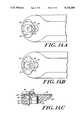
- FIGS. 14A, 14B, and 14Care two plan views and one elevation view respectively of a further stroke adjusting mechanism for use with the power tool of FIG. 1 and embodying features of the invention.
- FIG. 1shows a dental tool 10 according to the invention and having a manually deployable housing 12.
- the toolcan be seated in a power charging base 14 for recharging a rechargeable battery 16 carried in the housing.
- the housinghas an axial succession of three sections, namely a forward power head or tool section 12a, a central handle section 12b, and a back section 12c illustrated as housing the rechargeable battery 16 that drives an electric motor 18.
- the housing back section 12calso mounts a reservoir 20 of liquid, such as medication for selective dispensing to the dental site being treated with the tool.
- an on/off switch 22 and a fluid dispensing control switch 24are also mounted on the tool housing 12.
- the tool housingis sized for an operator to hold it with fingers encircled around it and with the thumb or forefinger able to reach and operate the on/off switch 22, the fluid dispensing switch 24, and a stroke-adjusting switch 26 located on the forward power head section 12a.
- the battery-driven motor 18rotates an input shaft 28 that is mounted within the housing 12.
- the driven rotation of the input shaft 28is coupled to an output shaft 30 for rotating it about an output axis 32.
- the output shaftextends along an axis 32 extending transversely to the axis of the shaft 28.
- a cam mechanism 34mounted in the tool power head section 12a and coupled with the output shaft 30 and with the stroke adjusting switch 26, imparts reciprocation to the tool output shaft 30 during this driven rotation.
- the length of the reciprocation strokeis adjustable by movement of the stroke switch 26.
- the tool output shaft 30can snap fit with any of several different tool implements 36a and 36b.
- the illustrated tool implement 36ais operated with rotation only, about the tool output shaft 30, as designated with arrow 38a.
- the tool implement 36bis preferably employed with combined rotation and axially reciprocation, as designated with arrows 38b.
- one feature of the tool 10is to drive interchangeable elements with exclusively rotary motion or with combined rotary and reciprocating motion.
- the illustrated tool housing 12mounts the input shaft 28 for rotation about an axis 40 longitudinal with the axial arrangement of the housing sections 12a, 12b, and 12c.
- the illustrated input shaft 28has, at its forward output end in the housing power section 12a, a bevel gear 42 that is drivingly engaged with a mating bevel gear 44 on a gear element 46.
- the output, gear end of the input shaft 28is mounted relative to the housing 12 for rotation about the axis 40 by way of a bearing 48.
- a pair of bearings 50 and 52 seated with the housingrotatably mount the gear element 46 for rotation about the output axis 32 and in fixed position axially along that axis for maintaining engagement between the bevel gears 42 and 44.
- the gear element 46is seated on the output shaft 30 and keyed with it, by internally projecting keys on the gear that slideably seat in axial key slots on the shaft 30, to rotate the output shaft in response to driven rotation which the gear element 46 receives from the input shaft 28.
- the keyed engagement of the gear element 46 with the output shaft 30allows the output shaft to reciprocate along the output axis 32 independent of the gear element 46.
- the illustrated output shaft 30has, in succession along the axis 32, a tool mounting end 30a, a bearing shaft section 30b that slideably seats within a bearing 54, a thrust section 30c engaged with a restoring spring 56, a key or spline section 30d fitted within the gear element 46, and a spline end section 30e illustrated as engaged with a thrust cam 60 that is part of the cam mechanism 34.
- the output shaft 30is thus mounted relative to the housing 12, by way of the bearing 54 and indirectly by way of the bearings 50 and 52 that engage the gear element 46 with which the shaft is engaged at the spline section 30d, for rotation about the output axis 30 and for limited axial reciprocation.
- the output shaft thrust section 30c in the illustrated embodimenthas a cylindrical collar 62 of enlarged radius for centering the restoring spring 56, and has a cylindrical flange 64 of larger radius for compressive abutment against the restoring spring 56.
- the illustrated restoring spring 56is a compressive spring of annular configuration seated around the shaft collar 62 and compressed between the axial face of the shaft flange 64 and an axially opposing annular shoulder 12d of the housing 12.
- the spring 56which preferably as illustrated is a compound wave spring, exerts a resilient reciprocation-restoring thrust on the output shaft 30 directed inward along the output axis 32, i.e. directed away from the shaft tool end 30a and upward in FIG. 2.
- the output shaft key section 30dmountingly interfits within the gear element 46 for rotation with the gear element about the axis 32 and for movement along that axis independent of the gear element.
- the output shaft spline section 30ehas a splined tubular inner passage into which a mounting stem of the cam 60 telescopically fittingly assembles.
- the illustrated splined passagehas a square cross section and the cam stem has a correspondingly square peg-like axially extending shape for secure fit within the spline section.
- FIG. 2shows a cam follower 62 of the cam mechanism 34 adjustably positioned out of engagement with the cam 60. In this position, the dental tool 10 output shaft 30 rotates without any axial reciprocation.
- the cam mechanism 34deflects the output shaft 30 to move the tool end 30a outward from the housing 12, i.e. downward in FIGS. 4 and 5 with each rotation of the shaft.
- the restoring springdrives the shaft back into the housing, i.e. upward in FIG. 2 to complete the reciprocating stroke.
- the illustrated cam mechanismemploys the cam 60 rotatable on the inner end of the shaft 30 and a cam follower 62 that selectively interferes with the cam 60, forcing it to deflect along the output axis 32, during each shaft rotation.
- the illustrated cam 60is a cylindrical member extending axially from the shaft 30, and selectively domed with a cam surface 60a, on the outer axial end.
- the cam surfaceengages the illustrated cam follower 62 at a fixed radial position.
- the cam surface 60agenerally extends transversely to the axis 32 about which it rotates and with progressively different circumferential positions thereon having progressively different bevels relative to a plane perpendicular the axis 32.
- the cam surfacethus faces axially, i.e. along the axis 32.
- the bevelscan have different contours, including flat, as in the embodiment of FIG. 7, and rounded as in the embodiment of FIG. 3 and with a different radius at different circumferential positions.
- FIG. 7Ashows the cam 60 in a first rotational position, designated 0°, where the cam surface 60a presents a maximal bevel to the cam follower 62.
- the cam 60At this rotational position of the cam 60, it is free of interfering engagement with the cam follower, with the follower adjusted to the position shown. Accordingly, there is no axial deflection of the cam, and correspondingly of the output shaft 30.
- the restoring spring 56hence maintains the output shaft 30 at a fully retracted position.
- FIG. 7Bshows that at a 45° rotational position of the cam, and symmetrically at a 225° rotation of the cam, the cam surface interferingly engages with the cam follower 62 to deflect the cam and correspondingly the output shaft by a stroke distance designated (x 1 ).
- FIG. 7Dshows that the 180° rotational position of the cam 60, the cam surface presents a minimal deflection to the cam follower 62 and there accordingly is maximal reciprocating displacement, designated (x 3 ) of the cam and correspondingly of the output shaft 30.
- FIG. 4shows the tool 10 power head at the minimal reciprocating displacement of the output shaft 30, corresponding to the 0° rotational position of the cam 60 as shown in FIG. 7A.
- FIG. 5shows the tool power head with maximal reciprocating displacement of the output shaft, corresponding to the 180° rotational position of the cam 60 as shown in FIG. 7D.
- the cam follower 62has the same position in each of FIGS. 4 and 5.
- FIG. 5shows the increased compression of the restoring spring 56, with increased displacement of the output shaft.
- FIG. 8illustrates the adjustment of the reciprocating stroke length due to adjustable positioning of the cam follower 62.
- the cam follower position as shown with solid linespresents minimal interference with the cam 60, in the illustrated instance no interference. Consequently, there is no reciprocation of the output shaft, as indicated with the solid line showing of the cam 60 and of the shaft 30 in FIG. 8.
- the cam followerWhen the cam follower is adjustably positioned for maximal interference, as shown in FIG. 8 with dash lines, it produces a maximal output shaft deflection, as illustrated with the dotted showing of the cam 60 and of the output shaft. At intermediate positions of the cam follower, the output shaft reciprocation has intermediate stroke lengths.
- the stroke adjusting switch 26 of the embodiment of the tool 10 shown FIG. 1is integral with the cam follower 62, as FIGS. 9 and 10 show.
- a one-piece adjustment member 64forms both the switch 26 and the cam follower 62. More particularly, the switch 26 is a protrusion on the member 64 outward from the housing 12, through a slot 12e (FIG. 2), for manual access by a user.
- the switch 26, and a of the member 64 which carries the switch and seats in the housing slot 12eare elongated along concentric circular paths, as shown in the plan views of FIGS. 9A and 10A.
- the housing slot 12efollows a circular path that matches the path of the web 64a which the slot seats.
- the cam follower 62is a beveled, concentrically inner extension of the adjustment member 64 and is radially located inward from the web 64a and is elongated along a non-circular path of progressively decreasing radius from one end 62a to the other end 62b.
- FIGS. 9A and 9Bshow the cam follower end 62a adjacent the cam 60.
- Movement of the switch 26 counterclockwise from the position shown in FIG. 9Abrings the cam follower increasingly into engagement with the cam 60, and accordingly produces progressively increasing reciprocation of the tool output shaft.
- FIGS. 10A and 10Bshow the position of maximal interference between the cam follower 62 and the cam 60, and correspondingly of maximal reciprocating stroke of the tool output shaft.
- FIGS. 11A through 11Dshow a second embodiment that employs a stroke adjusting switch 70 linked to a separate cam follower 72.
- the switch 70is on an adjustment member 74 that is slideable along a circular housing slot 12e, as in the embodiment of FIGS. 9 and 10.
- the switch 70 and correspondingly the housing slot 12e' of the embodiment of FIG. 11are illustrated as being on a top side of the housing, in contrast to the lateral side location shown in FIGS. 9 and 10.
- the adjustment member 74slidingly engages the cam follower 72 with an arcuate rim 76a of diminishing radius between circumferentially spaced ends 76a and 76b.
- the illustrated adjustment member 74also has a shelf 78 axially spaced from the rim 76 for seating the cam follower 72 between the rim and the shelf, as FIGS. 11B and 11D show.
- the cam follower 72is a wedge-like member arranged to move in a direction radial to the axis 32, i.e. along the arrow 80.
- the cam followercan be seated in a slot within the housing or have a slot radial to the axis 32 that receives a housing rail, or incorporate similar structures apparent to those skilled in the art to confine the movement of the cam follower to this sliding radial path.
- the cam followerhas a camming surface 72a at its radially innermost end and that conforms to the beveled camming surface on the cam 60.
- the radially outer end of the cam follower 72has a slot 72b that slidingly interfits with and receives the rim 76, for radially positioning the cam follower.
- FIGS. 11A and 11Bshow that when the adjustment member 74 is in the extreme counterclockwise position, the section of the cam-positioning rim 76 engaged with the cam follower 72 has a large radial value.
- the cam follower 72is accordingly positioned for minimal reciprocation of the tool output shaft. Movement of the adjustment member 74 clockwise from the position of FIGS. 11A and 11B increasingly moves the cam follower 72 radially inward toward the axis 32 and into increasing engagement with the cam 60, thereby producing increasing reciprocation of the tool output shaft.
- FIGS. 11C and 11Dshow the adjustment member 74 in its full clockwise rotational position, where it positions the cam follower 72 for maximal reciprocating stroke length.
- FIGS. 12A and 12Bshow a modification of the adjustment mechanism of FIG. 11 to provide a detent-like action at the travel limits of the adjustment member 74.
- the positioning rim 76'has bulbous enlargements at each circumferential end 76a' and 76b'.
- FIGS. 13A and 13BAnother embodiment of the stroke adjusting mechanism for the tool 10, shown in FIGS. 13A and 13B, employs a wedge-like cam follower 82 slidably seated within the housing between housing rails 84a and 84b that flank a housing slot 86.
- a thumb screw 88is threaded to the top of the cam follower, through the housing slot 86.
- a further embodiment of a tool according to the inventionhas, as shown in FIG. 14, a cam 60 as previously described on the end of the tool shaft 30 and engaged by a rotary adjustable cam follower 92 to select the stroke length of output shaft reciprocation.
- the tool of FIG. 14has a rotary stroke adjusting switch 94 accessible on the top side of the tool housing.
- the rotary switch 94is on a stem 96 that passes through a housing opening to mount a rotary cam follower 92 within the housing.
- a rotary sealing disk 98illustrated as carrying an 0-ring 100 that sealingly slidably engages the housing wall, is also mounted on the stem 96 to seal the housing opening from dirt, spillage and other debris.
- the stem 96which extends parallel to the output shaft axis 32, extends axially within the housing beyond the cam follower 92 to seat in a support socket 102, typically recessing an inner projection of the housing.
- the illustrated rotary cam follower 92has a circular frusto-conical shape to engage the cam 60 with a beveled camming surface.
- the cam followeris mounted off-center to the stem 96, and hence rotates about an off-center axis.
- the rotary adjustment switch 94 and cam follower 92are arranged to rotate as a unit with the stem 96, as well as with the sealing disk 98.
- Rotary adjustment of the switch 94rotates the cam follower 92 from the position shown in FIG. 14B, where it has minimal interference with the cam 60, progressively through 180° to the position shown in FIG. 14A, where the cam follower has maximal interference with the shaft carried cam 60.
- a further feature of the tool 10is that it can dispense liquid, such as medication or a dental cleaning preparation, to the dental site being treated.
- the tool housing 12carries a reservoir 20 and fluid dispensing switch 24, as shown in FIG. 1.
- a tube 104feeds liquid from the reservoir 20 to the forward power head section of the housing and, as shown in FIGS. 2 and 6, through a central bore 106 in the cam 60 and in output shaft 30.
- the illustrated tube 104extends substantially the full length of the output shaft to discharge liquid directly into whatever tool implement is fitted on the output shaft.
- the tool implement 36ashown in FIGS. 1 and 2, has a central passage 36c for receiving liquid discharged from the tube 104, and delivering it to the dental site.
- the passage of the tool implement 36apreferably ends with an orifice 36d that is normally closed and that opens in response to the implement being pressed onto a surface.
- the operator of the tool 10 fitted with the implement 36acan control the discharge of liquid both with the switch 24 on the tool housing and, further, by controlling the pressure with which the tool implement is pushed onto the dental site being treated.
- FIGS. 4 and 5show that the tool implement 36b also has a central passage for receiving liquid from the tube 104 and that feeds into radial discharge ducts from which the liquid is dispensed to the dental site being treated.
- a tool having the features described hereinabovethus rotates an output shaft and provides axial reciprocation of the shaft, with adjustable reciprocation stroke with a mechanism that operates with minimal vibration and without eccentric wobble-producing elements.
- the drive mechanism of the toolhas a high degree of axial symmetry that enhances smooth operation and enhances the ready delivery of liquid medication and like substances to the site being treated.
- the toolcan employ a number of different adjustment mechanisms for controlling the stroke of the axial reciprocation.
Landscapes
- Health & Medical Sciences (AREA)
- Dentistry (AREA)
- Epidemiology (AREA)
- Life Sciences & Earth Sciences (AREA)
- Animal Behavior & Ethology (AREA)
- General Health & Medical Sciences (AREA)
- Public Health (AREA)
- Veterinary Medicine (AREA)
- Dental Tools And Instruments Or Auxiliary Dental Instruments (AREA)
- Magnetic Resonance Imaging Apparatus (AREA)
Abstract
Description
Claims (25)
Priority Applications (6)
| Application Number | Priority Date | Filing Date | Title |
|---|---|---|---|
| US07/512,836US5145369A (en) | 1990-04-23 | 1990-04-23 | Dental tool driving apparatus having rotating and roto-reciprocating motions |
| JP91508057AJPH05507859A (en) | 1990-04-23 | 1991-04-17 | Dental instrument drive device with rotating and rotating reciprocating functions |
| EP91908310AEP0550441A1 (en) | 1990-04-23 | 1991-04-17 | Dental tool driving apparatus having rotating and roto-reciprocating motions |
| CA002081358ACA2081358A1 (en) | 1990-04-23 | 1991-04-17 | Dental tool having rotating and roto-reciprocating motions |
| PCT/US1991/002630WO1991016862A2 (en) | 1990-04-23 | 1991-04-17 | Dental tool having rotating and roto-reciprocating motions |
| AU77484/91AAU7748491A (en) | 1990-04-23 | 1991-04-17 | Dental tool driving apparatus having rotating and roto-reciprocating motions |
Applications Claiming Priority (1)
| Application Number | Priority Date | Filing Date | Title |
|---|---|---|---|
| US07/512,836US5145369A (en) | 1990-04-23 | 1990-04-23 | Dental tool driving apparatus having rotating and roto-reciprocating motions |
Publications (1)
| Publication Number | Publication Date |
|---|---|
| US5145369Atrue US5145369A (en) | 1992-09-08 |
Family
ID=24040783
Family Applications (1)
| Application Number | Title | Priority Date | Filing Date |
|---|---|---|---|
| US07/512,836Expired - LifetimeUS5145369A (en) | 1990-04-23 | 1990-04-23 | Dental tool driving apparatus having rotating and roto-reciprocating motions |
Country Status (6)
| Country | Link |
|---|---|
| US (1) | US5145369A (en) |
| EP (1) | EP0550441A1 (en) |
| JP (1) | JPH05507859A (en) |
| AU (1) | AU7748491A (en) |
| CA (1) | CA2081358A1 (en) |
| WO (1) | WO1991016862A2 (en) |
Cited By (67)
| Publication number | Priority date | Publication date | Assignee | Title |
|---|---|---|---|---|
| US5247218A (en)* | 1992-06-10 | 1993-09-21 | Sven J Eric | Hand held vibrating instrument |
| US5454718A (en)* | 1992-06-05 | 1995-10-03 | Kaltenbach & Voigt Gmbh & Co. | Handpiece head for a medical or dental handpiece with a reciprocating treatment tool |
| US5529494A (en)* | 1995-01-18 | 1996-06-25 | Vlacancich; Tanya | Dental tool driving device |
| WO1998057593A1 (en)* | 1997-06-19 | 1998-12-23 | Twist2It, Inc. | Drive mechanism for oscillatory dental tool |
| US5902105A (en)* | 1994-06-09 | 1999-05-11 | Kabushiki Kaisha Morita Seisakusho | Dental treatment apparatus with a root canal length measurement function |
| US5944523A (en)* | 1996-06-12 | 1999-08-31 | Micro-Mega International Manufactures | Dental assembly having multi-movement motor |
| US5974615A (en)* | 1996-07-10 | 1999-11-02 | Braun Aktiengesellschaft | Rotary electric toothbrush with stroke-type bristle movement |
| US6233773B1 (en)* | 1997-12-23 | 2001-05-22 | Hans J. Karge | Combination motorized toothbrush and plaque removal device |
| US6287115B1 (en) | 1998-11-17 | 2001-09-11 | L. Paul Lustig | Dental implant and tool and method for effecting a dental restoration using the same |
| US6350125B1 (en)* | 1999-08-27 | 2002-02-26 | Mani, Inc. | Contra-angle dental handpiece |
| US6409507B1 (en) | 1997-06-19 | 2002-06-25 | Twist2It, Inc. | Drive mechanism for oscillatory dental tool with improved bushing |
| EP1184002A3 (en)* | 2000-08-29 | 2003-02-05 | Mani, Inc. | Dental handpiece |
| US6574820B1 (en) | 1999-10-22 | 2003-06-10 | The Gillette Company | Brush head for toothbrush |
| WO2003005924A3 (en)* | 2001-07-12 | 2003-09-04 | Water Pik Inc | Dual motor oral hygiene device |
| US6725490B2 (en) | 2001-11-06 | 2004-04-27 | The Procter & Gamble Company | Complex motion toothbrush |
| USD500599S1 (en) | 2002-12-31 | 2005-01-11 | Water Pik, Inc. | Toothbrush handle |
| US20050026106A1 (en)* | 2003-02-13 | 2005-02-03 | Jefferies Steven R. | Application of dental materials to the oral cavity |
| US6920659B2 (en) | 2001-01-12 | 2005-07-26 | Water Pik, Inc. | Toothbrush |
| US6928685B1 (en) | 2001-11-06 | 2005-08-16 | The Procter & Gamble Company | Complex motion toothbrush |
| US6955539B2 (en) | 2001-07-12 | 2005-10-18 | Water Pik, Inc. | Characterization of motion of dual motor oral hygiene device |
| US20060015043A1 (en)* | 2004-07-13 | 2006-01-19 | Hornsby James R | Surface treatment device |
| US20060014119A1 (en)* | 2004-07-13 | 2006-01-19 | Bouneff Anthony B | Powered surgical instrument |
| US20060010623A1 (en)* | 2004-07-14 | 2006-01-19 | Crossman Scott P | Electric toothbrush with three dimensional motion |
| US7198487B2 (en) | 2002-12-31 | 2007-04-03 | Water Pik, Inc. | Whitening tip for dental flossing device |
| US7225494B2 (en) | 2001-11-06 | 2007-06-05 | Church & Dwight Co., Inc. | Multi-motion toothbrush |
| US20100017978A1 (en)* | 2004-01-02 | 2010-01-28 | Sonicscrubbers, Llc | Cleaning apparatus with reciprocating brush head |
| US20100178632A1 (en)* | 2005-01-26 | 2010-07-15 | Lindquist Sherrill F | Injection Distraction Device |
| US7874839B2 (en) | 2004-07-13 | 2011-01-25 | Westport Medical, Inc. | Powered surgical instruments |
| USD632090S1 (en) | 2009-10-06 | 2011-02-08 | Sonicscrubbers, Inc. | Toilet bowl cleaner stem |
| USD632490S1 (en) | 2009-10-06 | 2011-02-15 | Sonicscrubbers, Inc. | Toilet bowl cleaner with handle |
| USD632491S1 (en) | 2009-11-17 | 2011-02-15 | Sonicscrubbers, Inc. | Toilet bowl cleaner with rotatable scrubber |
| US20110143303A1 (en)* | 2009-12-10 | 2011-06-16 | Kerrhawe Sa | Dental composite applicator and related methods |
| US7967605B2 (en) | 2004-03-16 | 2011-06-28 | Guidance Endodontics, Llc | Endodontic files and obturator devices and methods of manufacturing same |
| FR2955243A1 (en)* | 2010-01-19 | 2011-07-22 | Micro Mega Int Mfg Sa | APPARATUS FOR MOVING TOOLS USED IN SURGERY |
| US8695726B2 (en) | 2010-12-29 | 2014-04-15 | Medical Enterprises LLC | Electric motor driven tool for orthopedic impacting |
| WO2014144262A1 (en)* | 2013-03-15 | 2014-09-18 | Vidacare Corporation | Drivers and drive systems |
| US8870872B2 (en) | 2004-01-26 | 2014-10-28 | Vidacare Corporation | Impact-driven intraosseous needle |
| US8943634B2 (en) | 2011-05-02 | 2015-02-03 | Water Pik, Inc. | Mechanically-driven, sonic toothbrush system |
| US8944069B2 (en) | 2006-09-12 | 2015-02-03 | Vidacare Corporation | Assemblies for coupling intraosseous (IO) devices to powered drivers |
| US8992535B2 (en) | 2002-05-31 | 2015-03-31 | Vidacare LLC | Apparatus and method to provide emergency access to bone marrow |
| US20150099242A1 (en)* | 2012-06-15 | 2015-04-09 | Sang Choon Cho | Implant Abutment |
| US20150164614A1 (en)* | 2013-12-10 | 2015-06-18 | Dentsply International Inc. | Multi-Directional Handpiece |
| US9072543B2 (en) | 2002-05-31 | 2015-07-07 | Vidacare LLC | Vascular access kits and methods |
| US9078637B2 (en) | 2002-05-31 | 2015-07-14 | Vidacare LLC | Apparatus and methods to harvest bone and bone marrow |
| WO2015119701A1 (en)* | 2014-02-04 | 2015-08-13 | Stevi, Llc | Electric interdental cleaning apparatus and systems useful for cleaning teeth and interdental spaces |
| US20150230881A1 (en)* | 2014-02-20 | 2015-08-20 | W&H Dentalwerk Bürmoos GmbH | Medical or dental hand instrument |
| US9468511B2 (en) | 2013-03-15 | 2016-10-18 | Water Pik, Inc. | Electronic toothbrush with vibration dampening |
| US9510910B2 (en) | 2006-09-12 | 2016-12-06 | Vidacare LLC | Medical procedures trays and related methods |
| US9717847B2 (en) | 2002-05-31 | 2017-08-01 | Teleflex Medical Devices S.Àr.L. | Apparatus and method to inject fluids into bone marrow and other target sites |
| US20170245960A1 (en)* | 2014-09-30 | 2017-08-31 | Matthew GHADAMI | Endodontic handpiece with rotational and vertical motion |
| US9987109B2 (en) | 2013-03-15 | 2018-06-05 | Water Pik, Inc. | Mechanically-driven, sonic toothbrush and water flosser |
| US10206492B2 (en) | 2015-10-09 | 2019-02-19 | Stevi, Llc | Brushes useful for cleaning teeth and interdental spaces |
| USD844997S1 (en) | 2016-12-15 | 2019-04-09 | Water Pik, Inc. | Toothbrush handle |
| USD845636S1 (en) | 2016-12-15 | 2019-04-16 | Water Pik, Inc. | Toothbrush handle |
| US10449023B2 (en) | 2015-07-08 | 2019-10-22 | Water Pik, Inc. | Oral cleansing device with energy conservation |
| US10492830B2 (en) | 2002-05-31 | 2019-12-03 | Teleflex Medical Devices S.À R.L. | Penetrator assembly for accessing bone marrow |
| US10561480B2 (en) | 2016-05-09 | 2020-02-18 | Water Pik, Inc. | Load sensing for oral devices |
| US10610008B2 (en) | 2016-12-15 | 2020-04-07 | Water Pik, Inc. | Brushing device with illumination features |
| USRE47963E1 (en) | 2010-12-29 | 2020-04-28 | DePuy Synthes Products, Inc. | Electric motor driven tool for orthopedic impacting |
| US10973545B2 (en) | 2002-05-31 | 2021-04-13 | Teleflex Life Sciences Limited | Powered drivers, intraosseous devices and methods to access bone marrow |
| US10973532B2 (en) | 2002-05-31 | 2021-04-13 | Teleflex Life Sciences Limited | Powered drivers, intraosseous devices and methods to access bone marrow |
| US20210339361A1 (en)* | 2020-05-01 | 2021-11-04 | Milwaukee Electric Tool Corporation | Rotary impact tool |
| US11234683B2 (en) | 2002-05-31 | 2022-02-01 | Teleflex Life Sciences Limited | Assembly for coupling powered driver with intraosseous device |
| US11266441B2 (en) | 2002-05-31 | 2022-03-08 | Teleflex Life Sciences Limited | Penetrator assembly for accessing bone marrow |
| US11337728B2 (en) | 2002-05-31 | 2022-05-24 | Teleflex Life Sciences Limited | Powered drivers, intraosseous devices and methods to access bone marrow |
| US11771439B2 (en) | 2007-04-04 | 2023-10-03 | Teleflex Life Sciences Limited | Powered driver |
| EP4279018A4 (en)* | 2021-06-09 | 2024-07-17 | Guilin Woodpecker Medical Instrument Co., Ltd. | DENTAL HANDPIECE AND HEAD, AND ROOT CANAL PREPARATION MACHINE |
Families Citing this family (4)
| Publication number | Priority date | Publication date | Assignee | Title |
|---|---|---|---|---|
| US7871598B1 (en) | 2000-05-10 | 2011-01-18 | Novartis Ag | Stable metal ion-lipid powdered pharmaceutical compositions for drug delivery and methods of use |
| ES2833372T3 (en) | 2010-06-19 | 2021-06-15 | Perimetrics Llc | System and procedure for determining the structural characteristics of an object |
| US9869606B2 (en) | 2011-06-18 | 2018-01-16 | Perimetrics, Llc | System and method for determining structural characteristics of an object |
| CN118329356A (en) | 2016-12-30 | 2024-07-12 | 佩里梅特里克斯股份有限公司 | System and method for determining structural characteristics of an object |
Citations (20)
| Publication number | Priority date | Publication date | Assignee | Title |
|---|---|---|---|---|
| US462530A (en)* | 1891-11-03 | Hand-piece for dental engines | ||
| US735968A (en)* | 1903-04-27 | 1903-08-11 | Victor Electric Company | Massaging implement. |
| GB648487A (en)* | 1947-07-09 | 1951-01-03 | Gustav Adolf Bjorkman | Apparatus for imposing vibratory impacts upon fillings of tooth cavities |
| US2968960A (en)* | 1959-12-08 | 1961-01-24 | Fulop Charles | Variable impact drill |
| US2970483A (en)* | 1959-02-17 | 1961-02-07 | Impact Rotor Tool Inc | Rotary drill and impact tool |
| US3521497A (en)* | 1967-07-24 | 1970-07-21 | Hilti Ag | Gearing arrangement for rotary and reciprocable hammer drill |
| US3602053A (en)* | 1968-04-30 | 1971-08-31 | Johann Steiner | Mechanically driven handtool |
| US3661018A (en)* | 1970-06-05 | 1972-05-09 | Richard K Keefer | Electric brusher |
| US3969823A (en)* | 1974-01-28 | 1976-07-20 | Nakanishi Dental Manufacturing Co., Ltd. | Dental handpiece for a motor driven reamer |
| US4084280A (en)* | 1977-02-25 | 1978-04-18 | Bob May | Tooth brush |
| US4156620A (en)* | 1974-07-18 | 1979-05-29 | Clemens George S | Apparatus and method for cleaning teeth |
| US4173828A (en)* | 1977-12-19 | 1979-11-13 | Leopold Paul Lustig | Interchangeable tool operating apparatus with plural motion |
| US4175324A (en)* | 1977-06-23 | 1979-11-27 | Kabushiki Kaisha Morita Sanshoku | Dental treatment tool |
| US4233850A (en)* | 1977-09-14 | 1980-11-18 | Ab Dentatus | Hand tool |
| US4289849A (en)* | 1980-03-31 | 1981-09-15 | Leopold Paul Lustig | Tools for drilling, reaming and the like with simultaneous angular and linear oscillatory motions |
| US4397055A (en)* | 1980-10-20 | 1983-08-09 | Cuchiara Samuel M | Reversable shaft with rotary and selective oscillating motion |
| GB2137503A (en)* | 1983-04-06 | 1984-10-10 | Micro Mega Sa | Dental hygiene apparatus |
| US4630493A (en)* | 1984-03-13 | 1986-12-23 | Sankyo Manufacturing Company, Ltd. | Cam arrangement |
| US4781588A (en)* | 1985-12-18 | 1988-11-01 | Daniel Granier | Counter-angle head for endodontic instrument |
| US4834653A (en)* | 1988-04-26 | 1989-05-30 | Dentatus International Ab | Dental instrument |
Family Cites Families (4)
| Publication number | Priority date | Publication date | Assignee | Title |
|---|---|---|---|---|
| NL124205C (en)* | 1965-11-25 | |||
| DE3008297C2 (en)* | 1980-03-04 | 1982-12-16 | Kaltenbach & Voigt Gmbh & Co, 7950 Biberach | Dental or dental technical vibration contra-angle |
| FR2563101B1 (en)* | 1984-04-20 | 1986-06-13 | Levy Guy | TRAINING HEAD FOR ENDODONTIC INTERVENTION INSTRUMENTS |
| US4544356A (en)* | 1984-11-15 | 1985-10-01 | Block Drug Company Inc. | Reciprocating dental prophylactic angular device |
- 1990
- 1990-04-23USUS07/512,836patent/US5145369A/ennot_activeExpired - Lifetime
- 1991
- 1991-04-17CACA002081358Apatent/CA2081358A1/ennot_activeAbandoned
- 1991-04-17WOPCT/US1991/002630patent/WO1991016862A2/ennot_activeApplication Discontinuation
- 1991-04-17AUAU77484/91Apatent/AU7748491A/ennot_activeAbandoned
- 1991-04-17JPJP91508057Apatent/JPH05507859A/enactivePending
- 1991-04-17EPEP91908310Apatent/EP0550441A1/ennot_activeWithdrawn
Patent Citations (20)
| Publication number | Priority date | Publication date | Assignee | Title |
|---|---|---|---|---|
| US462530A (en)* | 1891-11-03 | Hand-piece for dental engines | ||
| US735968A (en)* | 1903-04-27 | 1903-08-11 | Victor Electric Company | Massaging implement. |
| GB648487A (en)* | 1947-07-09 | 1951-01-03 | Gustav Adolf Bjorkman | Apparatus for imposing vibratory impacts upon fillings of tooth cavities |
| US2970483A (en)* | 1959-02-17 | 1961-02-07 | Impact Rotor Tool Inc | Rotary drill and impact tool |
| US2968960A (en)* | 1959-12-08 | 1961-01-24 | Fulop Charles | Variable impact drill |
| US3521497A (en)* | 1967-07-24 | 1970-07-21 | Hilti Ag | Gearing arrangement for rotary and reciprocable hammer drill |
| US3602053A (en)* | 1968-04-30 | 1971-08-31 | Johann Steiner | Mechanically driven handtool |
| US3661018A (en)* | 1970-06-05 | 1972-05-09 | Richard K Keefer | Electric brusher |
| US3969823A (en)* | 1974-01-28 | 1976-07-20 | Nakanishi Dental Manufacturing Co., Ltd. | Dental handpiece for a motor driven reamer |
| US4156620A (en)* | 1974-07-18 | 1979-05-29 | Clemens George S | Apparatus and method for cleaning teeth |
| US4084280A (en)* | 1977-02-25 | 1978-04-18 | Bob May | Tooth brush |
| US4175324A (en)* | 1977-06-23 | 1979-11-27 | Kabushiki Kaisha Morita Sanshoku | Dental treatment tool |
| US4233850A (en)* | 1977-09-14 | 1980-11-18 | Ab Dentatus | Hand tool |
| US4173828A (en)* | 1977-12-19 | 1979-11-13 | Leopold Paul Lustig | Interchangeable tool operating apparatus with plural motion |
| US4289849A (en)* | 1980-03-31 | 1981-09-15 | Leopold Paul Lustig | Tools for drilling, reaming and the like with simultaneous angular and linear oscillatory motions |
| US4397055A (en)* | 1980-10-20 | 1983-08-09 | Cuchiara Samuel M | Reversable shaft with rotary and selective oscillating motion |
| GB2137503A (en)* | 1983-04-06 | 1984-10-10 | Micro Mega Sa | Dental hygiene apparatus |
| US4630493A (en)* | 1984-03-13 | 1986-12-23 | Sankyo Manufacturing Company, Ltd. | Cam arrangement |
| US4781588A (en)* | 1985-12-18 | 1988-11-01 | Daniel Granier | Counter-angle head for endodontic instrument |
| US4834653A (en)* | 1988-04-26 | 1989-05-30 | Dentatus International Ab | Dental instrument |
Cited By (145)
| Publication number | Priority date | Publication date | Assignee | Title |
|---|---|---|---|---|
| US5454718A (en)* | 1992-06-05 | 1995-10-03 | Kaltenbach & Voigt Gmbh & Co. | Handpiece head for a medical or dental handpiece with a reciprocating treatment tool |
| US5247218A (en)* | 1992-06-10 | 1993-09-21 | Sven J Eric | Hand held vibrating instrument |
| US5902105A (en)* | 1994-06-09 | 1999-05-11 | Kabushiki Kaisha Morita Seisakusho | Dental treatment apparatus with a root canal length measurement function |
| US5529494A (en)* | 1995-01-18 | 1996-06-25 | Vlacancich; Tanya | Dental tool driving device |
| US5944523A (en)* | 1996-06-12 | 1999-08-31 | Micro-Mega International Manufactures | Dental assembly having multi-movement motor |
| US5974615A (en)* | 1996-07-10 | 1999-11-02 | Braun Aktiengesellschaft | Rotary electric toothbrush with stroke-type bristle movement |
| US6848451B2 (en)* | 1997-06-19 | 2005-02-01 | Twist2It, Inc. | Drive mechanism for oscillatory abrasion and polishing tool |
| KR100424670B1 (en)* | 1997-06-19 | 2004-03-24 | 트위스트2잇 인코포레이티드 | Drive mechanism for oscillatory dental tool |
| US6409507B1 (en) | 1997-06-19 | 2002-06-25 | Twist2It, Inc. | Drive mechanism for oscillatory dental tool with improved bushing |
| US20020157680A1 (en)* | 1997-06-19 | 2002-10-31 | Postal Robert T. | Drive mechanism for oscillatory abrasion and polishing tool |
| US5931672A (en)* | 1997-06-19 | 1999-08-03 | Postal; Robert T. | Drive mechanism for oscillatory dental tool |
| WO1998057593A1 (en)* | 1997-06-19 | 1998-12-23 | Twist2It, Inc. | Drive mechanism for oscillatory dental tool |
| US6233773B1 (en)* | 1997-12-23 | 2001-05-22 | Hans J. Karge | Combination motorized toothbrush and plaque removal device |
| US6287115B1 (en) | 1998-11-17 | 2001-09-11 | L. Paul Lustig | Dental implant and tool and method for effecting a dental restoration using the same |
| US20050042573A1 (en)* | 1998-11-17 | 2005-02-24 | Lustig L. Paul | Dental implant and tool and method for effecting a dental restoration using the same |
| US6786725B2 (en) | 1998-11-17 | 2004-09-07 | L. Paul Lustig | Dental implant and tool and method for effecting a dental restoration using the same |
| US6350125B1 (en)* | 1999-08-27 | 2002-02-26 | Mani, Inc. | Contra-angle dental handpiece |
| EP1078606A3 (en)* | 1999-08-27 | 2003-04-02 | Mani, Inc. | Contra-angle dental handpiece |
| US6574820B1 (en) | 1999-10-22 | 2003-06-10 | The Gillette Company | Brush head for toothbrush |
| US8220097B2 (en) | 1999-10-22 | 2012-07-17 | Braun Gmbh | Brush head for toothbrush |
| US7448107B2 (en) | 1999-10-22 | 2008-11-11 | The Gillette Company | Brush head for toothbrush |
| US20040088806A1 (en)* | 1999-10-22 | 2004-05-13 | The Gillette Company | Brush head for toothbrush |
| US6760946B2 (en)* | 1999-10-22 | 2004-07-13 | The Gillette Company | Brush head for toothbrush |
| US20030182747A1 (en)* | 1999-10-22 | 2003-10-02 | The Gillette Company | Brush head for toothbrush |
| US20070006403A1 (en)* | 1999-10-22 | 2007-01-11 | Depuydt Joseph A | Brush head for toothbrush |
| US20090106923A1 (en)* | 1999-10-22 | 2009-04-30 | The Gillette Company | Brush head for toothbrush |
| US7832042B2 (en) | 1999-10-22 | 2010-11-16 | The Gillette Company | Brush head for toothbrush |
| US20110010882A1 (en)* | 1999-10-22 | 2011-01-20 | Depuydt Joseph A | Brush head for toothbrush |
| EP1184002A3 (en)* | 2000-08-29 | 2003-02-05 | Mani, Inc. | Dental handpiece |
| US6920659B2 (en) | 2001-01-12 | 2005-07-26 | Water Pik, Inc. | Toothbrush |
| US6955539B2 (en) | 2001-07-12 | 2005-10-18 | Water Pik, Inc. | Characterization of motion of dual motor oral hygiene device |
| GB2394670B (en)* | 2001-07-12 | 2005-01-12 | Water Pik Inc | Dual motor oral hygiene device |
| WO2003005924A3 (en)* | 2001-07-12 | 2003-09-04 | Water Pik Inc | Dual motor oral hygiene device |
| EP1404245A4 (en)* | 2001-07-12 | 2006-04-05 | Water Pik Inc | Dual motor oral hygiene device |
| US6821119B2 (en) | 2001-07-12 | 2004-11-23 | Water Pik, Inc. | Dual motor oral hygiene device |
| GB2394670A (en)* | 2001-07-12 | 2004-05-05 | Water Pik Inc | Dual motor oral hygiene device |
| US6725490B2 (en) | 2001-11-06 | 2004-04-27 | The Procter & Gamble Company | Complex motion toothbrush |
| US6928685B1 (en) | 2001-11-06 | 2005-08-16 | The Procter & Gamble Company | Complex motion toothbrush |
| US7225494B2 (en) | 2001-11-06 | 2007-06-05 | Church & Dwight Co., Inc. | Multi-motion toothbrush |
| US11337728B2 (en) | 2002-05-31 | 2022-05-24 | Teleflex Life Sciences Limited | Powered drivers, intraosseous devices and methods to access bone marrow |
| US11291472B2 (en) | 2002-05-31 | 2022-04-05 | Teleflex Life Sciences Limited | Powered drivers, intraosseous devices and methods to access bone marrow |
| US10973532B2 (en) | 2002-05-31 | 2021-04-13 | Teleflex Life Sciences Limited | Powered drivers, intraosseous devices and methods to access bone marrow |
| US9393031B2 (en) | 2002-05-31 | 2016-07-19 | Vidacare LLC | Apparatus and method to provide emergency access to bone marrow |
| US11065382B2 (en) | 2002-05-31 | 2021-07-20 | Teleflex Life Sciences Limited | Apparatus to inject fluids into bone marrow and other target sites |
| US8992535B2 (en) | 2002-05-31 | 2015-03-31 | Vidacare LLC | Apparatus and method to provide emergency access to bone marrow |
| US11103282B1 (en) | 2002-05-31 | 2021-08-31 | Teleflex Life Sciences Limited | Powered drivers, intraosseous devices and methods to access bone marrow |
| US11234683B2 (en) | 2002-05-31 | 2022-02-01 | Teleflex Life Sciences Limited | Assembly for coupling powered driver with intraosseous device |
| US10973545B2 (en) | 2002-05-31 | 2021-04-13 | Teleflex Life Sciences Limited | Powered drivers, intraosseous devices and methods to access bone marrow |
| US11266441B2 (en) | 2002-05-31 | 2022-03-08 | Teleflex Life Sciences Limited | Penetrator assembly for accessing bone marrow |
| US9078637B2 (en) | 2002-05-31 | 2015-07-14 | Vidacare LLC | Apparatus and methods to harvest bone and bone marrow |
| US9872703B2 (en) | 2002-05-31 | 2018-01-23 | Teleflex Medical Devices S.Àr.L. | Vascular access kits and methods |
| US10166332B2 (en) | 2002-05-31 | 2019-01-01 | Teleflex Medical Devices S.À R.L. | Apparatus to inject fluids into bone marrow and other target sites |
| US10413282B2 (en) | 2002-05-31 | 2019-09-17 | Teleflex Medical Devices S.Àr.L. | Apparatus and methods to harvest bone and bone marrow |
| US10806491B2 (en) | 2002-05-31 | 2020-10-20 | Teleflex Life Sciences Limited | Vascular access kits and methods |
| US9717847B2 (en) | 2002-05-31 | 2017-08-01 | Teleflex Medical Devices S.Àr.L. | Apparatus and method to inject fluids into bone marrow and other target sites |
| US9072543B2 (en) | 2002-05-31 | 2015-07-07 | Vidacare LLC | Vascular access kits and methods |
| US10492830B2 (en) | 2002-05-31 | 2019-12-03 | Teleflex Medical Devices S.À R.L. | Penetrator assembly for accessing bone marrow |
| US11324521B2 (en) | 2002-05-31 | 2022-05-10 | Teleflex Life Sciences Limited | Apparatus and method to access bone marrow |
| USD500599S1 (en) | 2002-12-31 | 2005-01-11 | Water Pik, Inc. | Toothbrush handle |
| US7198487B2 (en) | 2002-12-31 | 2007-04-03 | Water Pik, Inc. | Whitening tip for dental flossing device |
| US20050026106A1 (en)* | 2003-02-13 | 2005-02-03 | Jefferies Steven R. | Application of dental materials to the oral cavity |
| US8047841B2 (en) | 2003-02-13 | 2011-11-01 | Dentsply International, Inc. | Application dental materials to the oral cavity |
| US8533886B2 (en) | 2004-01-02 | 2013-09-17 | Rubbermaid, Incorporated | Cleaning apparatus with reciprocating brush head |
| USD639068S1 (en) | 2004-01-02 | 2011-06-07 | Sonicscrubbers, Inc. | Brush head for cleaning apparatus |
| US7836538B2 (en)* | 2004-01-02 | 2010-11-23 | Sonicscrubbers, Inc. | Cleaning apparatus with reciprocating brush head |
| USD623411S1 (en) | 2004-01-02 | 2010-09-14 | Sonicscrubbers, Inc. | Brush head for cleaning apparatus |
| US20100017978A1 (en)* | 2004-01-02 | 2010-01-28 | Sonicscrubbers, Llc | Cleaning apparatus with reciprocating brush head |
| US8870872B2 (en) | 2004-01-26 | 2014-10-28 | Vidacare Corporation | Impact-driven intraosseous needle |
| US10052173B2 (en) | 2004-03-16 | 2018-08-21 | Guidance Endodontics, Llc | Endodontic files and obturator devices and methods of manufacturing same |
| US7967605B2 (en) | 2004-03-16 | 2011-06-28 | Guidance Endodontics, Llc | Endodontic files and obturator devices and methods of manufacturing same |
| US7874839B2 (en) | 2004-07-13 | 2011-01-25 | Westport Medical, Inc. | Powered surgical instruments |
| US20060015043A1 (en)* | 2004-07-13 | 2006-01-19 | Hornsby James R | Surface treatment device |
| US20060014119A1 (en)* | 2004-07-13 | 2006-01-19 | Bouneff Anthony B | Powered surgical instrument |
| US7794415B2 (en) | 2004-07-13 | 2010-09-14 | S.C. Johnson & Son, Inc. | Surface treatment device |
| US20060010623A1 (en)* | 2004-07-14 | 2006-01-19 | Crossman Scott P | Electric toothbrush with three dimensional motion |
| US8790286B2 (en)* | 2005-01-26 | 2014-07-29 | Raintree Essix, LLC | Injection distraction device |
| US20100178632A1 (en)* | 2005-01-26 | 2010-07-15 | Lindquist Sherrill F | Injection Distraction Device |
| US11426249B2 (en) | 2006-09-12 | 2022-08-30 | Teleflex Life Sciences Limited | Vertebral access system and methods |
| US8944069B2 (en) | 2006-09-12 | 2015-02-03 | Vidacare Corporation | Assemblies for coupling intraosseous (IO) devices to powered drivers |
| US9510910B2 (en) | 2006-09-12 | 2016-12-06 | Vidacare LLC | Medical procedures trays and related methods |
| US12089972B2 (en) | 2006-09-12 | 2024-09-17 | Teleflex Life Sciences Limited | Apparatus and methods for biopsy and aspiration of bone marrow |
| US11771439B2 (en) | 2007-04-04 | 2023-10-03 | Teleflex Life Sciences Limited | Powered driver |
| USD632490S1 (en) | 2009-10-06 | 2011-02-15 | Sonicscrubbers, Inc. | Toilet bowl cleaner with handle |
| USD632090S1 (en) | 2009-10-06 | 2011-02-08 | Sonicscrubbers, Inc. | Toilet bowl cleaner stem |
| USD632491S1 (en) | 2009-11-17 | 2011-02-15 | Sonicscrubbers, Inc. | Toilet bowl cleaner with rotatable scrubber |
| US9452027B2 (en) | 2009-12-10 | 2016-09-27 | Kerrhawe Sa | Dental composite applicator and related methods |
| US20110143303A1 (en)* | 2009-12-10 | 2011-06-16 | Kerrhawe Sa | Dental composite applicator and related methods |
| FR2955243A1 (en)* | 2010-01-19 | 2011-07-22 | Micro Mega Int Mfg Sa | APPARATUS FOR MOVING TOOLS USED IN SURGERY |
| USRE47997E1 (en) | 2010-12-29 | 2020-05-19 | DePuy Synthes Products, Inc. | Electric motor driven tool for orthopedic impacting |
| USRE48387E1 (en) | 2010-12-29 | 2021-01-12 | DePuy Synthes Products, Inc. | Electric motor driven tool for orthopedic impacting |
| US8695726B2 (en) | 2010-12-29 | 2014-04-15 | Medical Enterprises LLC | Electric motor driven tool for orthopedic impacting |
| US12023045B2 (en) | 2010-12-29 | 2024-07-02 | DePuy Synthes Products, Inc. | Electric motor driven tool for orthopedic impacting |
| USRE49666E1 (en) | 2010-12-29 | 2023-09-26 | Depuy Synthes Products, Inc | Electric motor driven tool for orthopedic impacting |
| USRE48184E1 (en) | 2010-12-29 | 2020-09-01 | DePuy Synthes Products, Inc. | Electric motor driven tool for orthopedic impacting |
| USRE48251E1 (en) | 2010-12-29 | 2020-10-13 | DePuy Synthes Products, Inc. | Electric motor driven tool for orthopedic impacting |
| USRE48388E1 (en) | 2010-12-29 | 2021-01-12 | DePuy Synthes Products, Inc. | Electric motor driven tool for orthopedic impacting |
| US11076867B2 (en) | 2010-12-29 | 2021-08-03 | DePuy Synthes Products, Inc. | Electric motor driven tool for orthopedic impacting |
| US9901354B2 (en) | 2010-12-29 | 2018-02-27 | Medical Enterprises, Llc | Electric motor driven tool for orthopedic impacting |
| USRE47963E1 (en) | 2010-12-29 | 2020-04-28 | DePuy Synthes Products, Inc. | Electric motor driven tool for orthopedic impacting |
| US10420567B2 (en) | 2010-12-29 | 2019-09-24 | DePuy Synthes Products, Inc. | Electric motor driven tool for orthopedic impacting |
| US9144477B2 (en) | 2011-05-02 | 2015-09-29 | Water Pik, Inc. | Mechanically-driven, sonic toothbrush system |
| US8943634B2 (en) | 2011-05-02 | 2015-02-03 | Water Pik, Inc. | Mechanically-driven, sonic toothbrush system |
| US20150099242A1 (en)* | 2012-06-15 | 2015-04-09 | Sang Choon Cho | Implant Abutment |
| US9713514B2 (en)* | 2012-06-15 | 2017-07-25 | Ebi Co., Ltd. | Implant abutment |
| US10918469B2 (en) | 2013-03-15 | 2021-02-16 | Water Pik, Inc. | Toothbrush with fluid directing drive assembly |
| US9468511B2 (en) | 2013-03-15 | 2016-10-18 | Water Pik, Inc. | Electronic toothbrush with vibration dampening |
| US9987109B2 (en) | 2013-03-15 | 2018-06-05 | Water Pik, Inc. | Mechanically-driven, sonic toothbrush and water flosser |
| USD878765S1 (en) | 2013-03-15 | 2020-03-24 | Water Pik, Inc. | Brush head for oral cleansing device |
| US9615816B2 (en) | 2013-03-15 | 2017-04-11 | Vidacare LLC | Drivers and drive systems |
| US10716582B2 (en) | 2013-03-15 | 2020-07-21 | Teleflex Life Sciences Limited | Drivers and drive systems |
| WO2014144262A1 (en)* | 2013-03-15 | 2014-09-18 | Vidacare Corporation | Drivers and drive systems |
| US11744690B2 (en) | 2013-03-15 | 2023-09-05 | Water Pik, Inc. | Toothbrush tip |
| US11737765B2 (en) | 2013-03-15 | 2023-08-29 | Teleflex Life Sciences Limited | Drivers and drive systems |
| US10828137B2 (en) | 2013-03-15 | 2020-11-10 | Water Pik, Inc. | Brush tip with motion transfer and securing engagement structures |
| USD959840S1 (en) | 2013-03-15 | 2022-08-09 | Water Pik, Inc. | Brush head for oral cleansing device |
| US11399925B2 (en) | 2013-03-15 | 2022-08-02 | Water Pik, Inc. | Wirelessly controlled oral irrigator |
| US11351018B2 (en) | 2013-03-15 | 2022-06-07 | Water Pik, Inc. | Oral cleansing device with removable base |
| US9833299B2 (en)* | 2013-12-10 | 2017-12-05 | Dentsply International Inc. | Multi-directional handpiece |
| WO2015089239A1 (en) | 2013-12-10 | 2015-06-18 | Dentsply International Inc. | Multi-directional handpiece |
| EP3763318A1 (en) | 2013-12-10 | 2021-01-13 | Dentsply Sirona Inc. | Multi-directional handpiece |
| US20180049843A1 (en)* | 2013-12-10 | 2018-02-22 | Dentsply Sirona Inc. | Multi-Directional Handpiece |
| US10350028B2 (en)* | 2013-12-10 | 2019-07-16 | Dentsply Sirona Inc. | Multi-directional handpiece |
| EP3545898A1 (en) | 2013-12-10 | 2019-10-02 | Dentsply Sirona Inc. | Multi-directional handpiece |
| US20150164614A1 (en)* | 2013-12-10 | 2015-06-18 | Dentsply International Inc. | Multi-Directional Handpiece |
| CN106470640A (en)* | 2014-02-04 | 2017-03-01 | 史迪伍有限责任公司 | For cleaning electronic teeth space cleaning device and the system of tooth and teeth space |
| WO2015119701A1 (en)* | 2014-02-04 | 2015-08-13 | Stevi, Llc | Electric interdental cleaning apparatus and systems useful for cleaning teeth and interdental spaces |
| US9339356B2 (en) | 2014-02-04 | 2016-05-17 | Stevi Llc | Electric interdental cleaning apparatus and systems useful for cleaning teeth and interdental spaces |
| US9333059B2 (en) | 2014-02-04 | 2016-05-10 | Stevi Llc | Multi-function electric brush apparatus and systems useful for cleaning teeth and interdental spaces |
| US20150230881A1 (en)* | 2014-02-20 | 2015-08-20 | W&H Dentalwerk Bürmoos GmbH | Medical or dental hand instrument |
| US10092370B2 (en)* | 2014-02-20 | 2018-10-09 | W&H Dentalwerk Bürmoos GmbH | Medical or dental hand instrument |
| US20170245960A1 (en)* | 2014-09-30 | 2017-08-31 | Matthew GHADAMI | Endodontic handpiece with rotational and vertical motion |
| US10449023B2 (en) | 2015-07-08 | 2019-10-22 | Water Pik, Inc. | Oral cleansing device with energy conservation |
| US11284980B2 (en) | 2015-07-08 | 2022-03-29 | Water Pik, Inc. | Oral cleansing device with rotatable fluid connector |
| US10206492B2 (en) | 2015-10-09 | 2019-02-19 | Stevi, Llc | Brushes useful for cleaning teeth and interdental spaces |
| US10561480B2 (en) | 2016-05-09 | 2020-02-18 | Water Pik, Inc. | Load sensing for oral devices |
| USD845636S1 (en) | 2016-12-15 | 2019-04-16 | Water Pik, Inc. | Toothbrush handle |
| US11013315B2 (en) | 2016-12-15 | 2021-05-25 | Water Pik, Inc. | Light diffuser for oral cleansing devices |
| US10610008B2 (en) | 2016-12-15 | 2020-04-07 | Water Pik, Inc. | Brushing device with illumination features |
| USD906688S1 (en) | 2016-12-15 | 2021-01-05 | Water Pik, Inc. | Toothbrush handle |
| USD844997S1 (en) | 2016-12-15 | 2019-04-09 | Water Pik, Inc. | Toothbrush handle |
| USD881584S1 (en) | 2016-12-15 | 2020-04-21 | Water Pik, Inc. | Toothbrush handle |
| US20210339361A1 (en)* | 2020-05-01 | 2021-11-04 | Milwaukee Electric Tool Corporation | Rotary impact tool |
| US12053862B2 (en)* | 2020-05-01 | 2024-08-06 | Milwaukee Electric Tool Corporation | Rotary impact tool |
| US20240391067A1 (en)* | 2020-05-01 | 2024-11-28 | Milwaukee Electric Tool Corporation | Rotary impact tool |
| EP4279018A4 (en)* | 2021-06-09 | 2024-07-17 | Guilin Woodpecker Medical Instrument Co., Ltd. | DENTAL HANDPIECE AND HEAD, AND ROOT CANAL PREPARATION MACHINE |
Also Published As
| Publication number | Publication date |
|---|---|
| AU7748491A (en) | 1991-11-27 |
| EP0550441A1 (en) | 1993-07-14 |
| JPH05507859A (en) | 1993-11-11 |
| WO1991016862A3 (en) | 1993-03-18 |
| CA2081358A1 (en) | 1991-10-24 |
| WO1991016862A2 (en) | 1991-11-14 |
| EP0550441A4 (en) | 1993-05-12 |
Similar Documents
| Publication | Publication Date | Title |
|---|---|---|
| US5145369A (en) | Dental tool driving apparatus having rotating and roto-reciprocating motions | |
| US20220168177A1 (en) | Percussion Massager Having Variable and Selectable Stroke Length | |
| US8172572B2 (en) | Dental tool displacement apparatus with slow rotational motion | |
| EP3763318B1 (en) | Multi-directional handpiece | |
| US20050126803A1 (en) | Power tool | |
| US4175299A (en) | Power toothbrush or the like with orbital brush action | |
| US4498463A (en) | Massage apparatus | |
| US6840947B2 (en) | Device for surgery of the cornea | |
| JPH06197914A (en) | Hand piece head for hand piece for medical treatment or dentistry | |
| CN1781678B (en) | Hand machine tool | |
| EP0399503B1 (en) | Oscillating-type mowing apparatus | |
| US5131147A (en) | Reciprocal cam-powered razor | |
| US20060076436A1 (en) | Device for showering | |
| US20200121904A1 (en) | Reversible rotary tattoo machine with centric cam | |
| JP4125993B2 (en) | Air-driven dental handpiece and power adjustment adapter | |
| CN103465230B (en) | Swing-type power tool | |
| JP3163266B2 (en) | Stroke adjustment device for reciprocating pump | |
| KR830001274B1 (en) | Powered toothbrush | |
| EP0025073A1 (en) | Power toothbrush or the like with orbital brush action | |
| JPH05123346A (en) | Liquid energizing device |
Legal Events
| Date | Code | Title | Description |
|---|---|---|---|
| AS | Assignment | Owner name:LUSTIG, L. PAUL, MASSACHUSETTS Free format text:ASSIGNMENT OF ASSIGNORS INTEREST.;ASSIGNOR:TYBINKOWSKI, ANDREW;REEL/FRAME:005298/0054 Effective date:19900423 | |
| STCF | Information on status: patent grant | Free format text:PATENTED CASE | |
| FEPP | Fee payment procedure | Free format text:PAYOR NUMBER ASSIGNED (ORIGINAL EVENT CODE: ASPN); ENTITY STATUS OF PATENT OWNER: SMALL ENTITY | |
| REFU | Refund | Free format text:REFUND OF EXCESS PAYMENTS PROCESSED (ORIGINAL EVENT CODE: R169); ENTITY STATUS OF PATENT OWNER: SMALL ENTITY | |
| FPAY | Fee payment | Year of fee payment:4 | |
| FEPP | Fee payment procedure | Free format text:PAT HLDR NO LONGER CLAIMS SMALL ENT STAT AS INDIV INVENTOR (ORIGINAL EVENT CODE: LSM1); ENTITY STATUS OF PATENT OWNER: SMALL ENTITY Free format text:PAYOR NUMBER ASSIGNED (ORIGINAL EVENT CODE: ASPN); ENTITY STATUS OF PATENT OWNER: SMALL ENTITY Free format text:PAYER NUMBER DE-ASSIGNED (ORIGINAL EVENT CODE: RMPN); ENTITY STATUS OF PATENT OWNER: SMALL ENTITY Free format text:PAT HOLDER CLAIMS SMALL ENTITY STATUS - SMALL BUSINESS (ORIGINAL EVENT CODE: SM02); ENTITY STATUS OF PATENT OWNER: SMALL ENTITY | |
| REFU | Refund | Free format text:REFUND - PAYMENT OF MAINTENANCE FEE, 4TH YR, SMALL ENTITY (ORIGINAL EVENT CODE: R283); ENTITY STATUS OF PATENT OWNER: SMALL ENTITY | |
| FPAY | Fee payment | Year of fee payment:8 | |
| REMI | Maintenance fee reminder mailed | ||
| FPAY | Fee payment | Year of fee payment:12 | |
| SULP | Surcharge for late payment | Year of fee payment:11 |