US5145092A - Syrup dispensing system for soft drink dispenser - Google Patents
Syrup dispensing system for soft drink dispenserDownload PDFInfo
- Publication number
- US5145092A US5145092AUS07/664,775US66477591AUS5145092AUS 5145092 AUS5145092 AUS 5145092AUS 66477591 AUS66477591 AUS 66477591AUS 5145092 AUS5145092 AUS 5145092A
- Authority
- US
- United States
- Prior art keywords
- syrup
- pumps
- dispensing
- pump
- control means
- Prior art date
- Legal status (The legal status is an assumption and is not a legal conclusion. Google has not performed a legal analysis and makes no representation as to the accuracy of the status listed.)
- Expired - Fee Related
Links
- 235000020357syrupNutrition0.000titleclaimsabstractdescription123
- 239000006188syrupSubstances0.000titleclaimsabstractdescription123
- 235000014214soft drinkNutrition0.000titleclaimsabstractdescription19
- 230000002401inhibitory effectEffects0.000claimsdescription4
- 230000004913activationEffects0.000claimsdescription2
- 230000003213activating effectEffects0.000claims1
- CURLTUGMZLYLDI-UHFFFAOYSA-NCarbon dioxideChemical compoundO=C=OCURLTUGMZLYLDI-UHFFFAOYSA-N0.000description11
- 229910002092carbon dioxideInorganic materials0.000description10
- 239000001569carbon dioxideSubstances0.000description10
- 239000000523sampleSubstances0.000description6
- CDBYLPFSWZWCQE-UHFFFAOYSA-LSodium CarbonateChemical compound[Na+].[Na+].[O-]C([O-])=OCDBYLPFSWZWCQE-UHFFFAOYSA-L0.000description3
- 230000005484gravityEffects0.000description3
- 238000000034methodMethods0.000description3
- 230000001105regulatory effectEffects0.000description3
- 241000237858GastropodaSpecies0.000description2
- BVKZGUZCCUSVTD-UHFFFAOYSA-LCarbonateChemical compound[O-]C([O-])=OBVKZGUZCCUSVTD-UHFFFAOYSA-L0.000description1
- 235000013361beverageNutrition0.000description1
- 238000010586diagramMethods0.000description1
- 230000010339dilationEffects0.000description1
- 230000009977dual effectEffects0.000description1
- 238000002347injectionMethods0.000description1
- 239000007924injectionSubstances0.000description1
- 238000009434installationMethods0.000description1
- 239000000203mixtureSubstances0.000description1
- XLYOFNOQVPJJNP-UHFFFAOYSA-NwaterSubstancesOXLYOFNOQVPJJNP-UHFFFAOYSA-N0.000description1
Images
Classifications
- B—PERFORMING OPERATIONS; TRANSPORTING
- B67—OPENING, CLOSING OR CLEANING BOTTLES, JARS OR SIMILAR CONTAINERS; LIQUID HANDLING
- B67D—DISPENSING, DELIVERING OR TRANSFERRING LIQUIDS, NOT OTHERWISE PROVIDED FOR
- B67D1/00—Apparatus or devices for dispensing beverages on draught
- B67D1/04—Apparatus utilising compressed air or other gas acting directly or indirectly on beverages in storage containers
- B—PERFORMING OPERATIONS; TRANSPORTING
- B67—OPENING, CLOSING OR CLEANING BOTTLES, JARS OR SIMILAR CONTAINERS; LIQUID HANDLING
- B67D—DISPENSING, DELIVERING OR TRANSFERRING LIQUIDS, NOT OTHERWISE PROVIDED FOR
- B67D1/00—Apparatus or devices for dispensing beverages on draught
- B67D1/08—Details
- B67D1/10—Pump mechanism
Definitions
- the invention hereinresides in the art of soft drink dispensers and, more particularly, to a syrup dispensing system therefore.
- the inventionpresents a syrup dispensing system which is operative for implementation with any of various types of syrup sources.
- soft drinkstypically comprise a combination of soda or carbonated water and an appropriate flavoring syrup.
- soft drink dispenserstypically include both a soda dispensing system and a syrup dispensing system, the soda and syrup being combined at the dispensing head or within the drink receptacle.
- the invention hereinrelates particularly to a syrup dispensing system for such soft drink dispensers.
- Another aspect of the inventionis the provision of a syrup dispensing system for a soft drink dispenser in which higher dispensing rates can be achieved than with previously known systems.
- Still a further aspect of the inventionis the provision of a syrup dispensing system for a soft drink dispenser in which a bag-in-box system may be employed without the necessity of a pump being associated with each bag-in-box station.
- Yet another aspect of the inventionis the provision of a syrup dispensing system for a soft drink dispenser which is less costly, while being more reliable and accurate than previously known systems.
- Still a further aspect of the inventionis the provision of a syrup dispensing system for a soft drink dispenser which eliminates the likelihood of gas entering the dispensing line.
- An additional aspect of the inventionis the provision of a syrup dispensing system for a soft drink dispenser in which various sources of syrup can be employed and/or mixed, including bag-in-box sources, pressurized canister sources, and gravity feed bulk sources.
- a syrup dispensing assemblyfor a soft drink dispenser, comprising: a supply of syrup; a dispensing head; pump means interposed between said supply of syrup and dispensing head for receiving syrup from said supply and passing it to said dispensing head; and vacuum generating means interconnected with said pump means for drawing syrup from said supply to said pump means.
- a syrup dispensing assemblyfor a soft drink dispenser, comprising: a plurality of pumps, each pump defining a chamber; a plurality of sources of syrup in selective communication with said chambers of said pumps; a pressure source in selective communication with said chambers of said pumps; a vacuum source in selective communication with said chambers of said pumps; and control means interconnected with said pressure source and said vacuum source for selectively and mutually exclusively enabling and inhibiting communication of said pressure and vacuum sources with said chambers of said pumps.
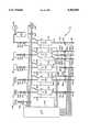
- the syrup dispensing assembly for a soft drink dispenseris designated generally by the numeral 10.
- the assembly 10is shown to operate with various sources of syrup supply.
- several syrupsare provided in the bag-in-box fashion as at 12, 14.
- Bulk reservoirs of other syrupsare provided by means of the tanks 16, 18.
- a pressurized syrup tank 20provides still another syrup under a pressure head provided by a regulated source of CO 2 gas 22.
- the source 22is regulated to provide for a substantially constant pressure head within the tank 20.
- each of the syrup supply sources 12-20is one of the dispensing pumps 24-32. These pumps are generally well known in the art, as shown, by way of example, in U.S. Pat. No. 4,903,862.
- the pumps 24-32are pressure driven, obviating any need for pistons, diaphragms, and the like.
- the pumps 24-32communicate with associated syrup supply sources 12-20 through respective conduits or fill lines 34-42. Positioned within each of the fill lines 34-42 and interposed between the respective pumps 24-32 and syrup supply sources 12-20 are respective check valves 44-52, serving as safety means to preclude any back pressure from the pumps reaching the syrup supplies.
- fill valves 54-62are interposed in the fill lines 34-42, the same preferably being electrically actuated solenoid valves as are well known to those skilled in the art.
- each of the pumps 24-32are respective dispensing lines.
- the pump 24has a single dispensing line 64, indicating that it services a single dispensing head or station.
- the pump 26has dual dispensing lines 66a and 66b suggesting that this pump may service two separate dispensing heads or stations.
- the pumps 28, 32similar to the pump 24, have respective single dispensing lines 68, 72, again indicating that only a single dispensing station or head is serviced.
- pump 30has three dispensing lines 70a, 70b, and 70c indicating that three separate dispensing heads or stations can be serviced by that pump. It will be appreciated that, in a typical syrup dispensing system, each of the pumps would service the same number of dispensing heads or stations.
- dispensing heads 74, 76a, 76b, 78, 80a, 80b, 80c, 82are dispensing heads of the type well known in the art, and for purposes of this invention may be of any suitable nature.
- dispensing valves 84, 86a, 86b, 88, 90a, 90b, 90c, 92Received within the respective dispensing lines and interposed between the associated pump and dispensing head are respective dispensing valves 84, 86a, 86b, 88, 90a, 90b, 90c, 92.
- These valvesagain as well known and understood by those skilled in the art, would typically comprise an electrically actuated solenoid dispensing valve.
- each of the dispensing linesbetween the respective pumps and dispensing heads, of a metering adjustment valve 94, 96a, 96b, 98, 100a, 100b, 100c, 102.
- metering valvesare provided with screw adjustments, as particularly illustrated with the metering valve 94, to regulate or adjust the rate of flow of syrup through the associated line 64 and dispensing head 74.
- each of the pumps 24-32will typically be subjected to the same pressure head for dispensing of syrup.
- the rates of flow of the syrups from the associated dispensing headsmay be set by means of dilation or constriction of the associated metering valves 94-102.
- each of the pumps 24-32Received within each of the pumps 24-32 are level sensors 104-112, each comprising a pair of probes set at a particular level within the reservoir or cavity of the associated pump.
- Such level sensorsare now well known to those skilled in the art, and comprise a switch which is "made” and “broken” by the syrup within the cavity or reservoir. It will be appreciated that the level sensors 104-112 may be at various positions, and need not be horizontally aligned. In such cases, the uppermost probe of the level sensor would establish the "full" level for the syrup.
- each of the level sensors 104-112has a uniquely associated resistor 114-122 connected to an appropriate voltage source. As further shown, the other side of the level sensors 104-112 is connected to ground.
- a pressurized source of CO 2 gas 124which is preferably regulated to attain a relatively constant pressure output.
- a three-way valve 126commonly used in such dispensing systems, is interposed between the gas pressure source 124 and the conduit or manifold 128 which feeds to the interior cavity of all of the pumps 24-32.
- a vacuum pump 130Also connected to the manifold 128 and servicing the cavities of each of the pumps 24-32 is a vacuum pump 130.
- a valve 132may, if desired, be interposed within the manifold 128 between the vacuum pump 130 and the pumps 24-32.
- control unit 134such as a dedicated microprocessor or the like. As shown, the microprocessor is interconnected with each of the fill valves 54-62, level sensors 114-122, and dispensing valves 84-92. Additionally, the control unit 134 is interconnected with the three-way valve 126 and the vacuum pump 130 and valve 128 as shown. The function and operation of the control unit 134 in conjunction with the syrup dispensing assembly 10 will become apparent below.
- each of the pumps 24-32is filled to the levels set by the level sensors 104-112.
- each of the supplies 12-20will contain a separate and distinct flavoring syrup, such that each of the pumps 24-32 will similarly have an associated distinct syrup.
- the microprocessor 134actuates the three-way valve 126 to allow the pressurized CO 2 from the source 124 to communicate through the manifold 128 to the interior of each of the pumps 24-32. Accordingly, the pumps have a set pressure head therein.
- the control unit 134then actuates the selected dispensing valve 84-92 such that syrup is urged by the pressure head out of the chamber of the pump and out of the associated dispensing head 74-82.
- the control unit 134deactivates the dispensing valve 84-92, terminating the syrup flow.
- the three way valve 126is closed to disconnect the pressurized source of CO 2 gas 124 from the pumps 24-32. If desired, the three-way valve 126 can, at this time, be actuated to vent the pumps 24-32 to atmosphere for a short period of time, depressurizing the pumps.
- the control unit 134then opens the fill valve 54, allowing communication of syrup from the bag-in-box supply 12 through the conduit 34 and into the chamber of the pump 24 under control of the vacuum generated by the pump 130. Syrup enters the pump 24 until the probes of the level sensor 104 are interconnected by the syrup, indicating a full level. At this time a "ground" signal is passed to the appropriate input of the unit 134, indicating that the pump 24 has been replenished to its full level. The valve 54 is then closed, the vacuum pump 130 is deactivated, and the valve 132 is closed, terminating the replenishing cycle.
- control unit 134functions to assure that the pressure source 124 and the vacuum source 130 are mutually exclusively interconnected to the manifold 128 and, hence, the pumps 24-32.
- the pressure sourcecommunicates with pumps for a dispensing cycle, while the vacuum source communicates with the pumps for a refill cycle.
- a plurality of bag-in-box or bulk syrup suppliesmay be used in a single syrup dispensing system, with full depletion and use of the supplies being attained by a single vacuum pump servicing all of the supplies.
- the apparatus and techniquemay also be employed with pressurized syrup supply sources with the vacuum pump assisting in and assuring the transfer of syrup from the supply source to the pumps and precluding the injection of gas "slugs" and the like into the dispensing line.
- the metering adjustment valves 94-102are provided in respective dispensing lines to adjust the rate of syrup dispensing to accommodate the various different syrups of the pumps 24-32, all being dispensed under the same pressure head.
- control unit or microprocessor 134will typically include a timing function associated with the refill cycle.
- the vacuum pump 130 and valve 132are activated and the appropriate fill valve or valves 54-62 are similarly activated. From this point of activation, a timer is started. If the associated pump 24-32 is not refilled to the set level of the associated sensor 104-112 within a set period of time, the microprocessor 134 determines that the associated supply 12-20 is empty and that the pump is therefore incapable of refilling.
- the appropriate fill valve 54-62is closed, and the control unit 134 actuates an appropriate indicia such as a lamp or the like to indicate that a particular syrup supply is empty.
- the associated dispensing valve 84-92is similarly disabled by the control unit 134.
Landscapes
- Engineering & Computer Science (AREA)
- Mechanical Engineering (AREA)
- Devices For Dispensing Beverages (AREA)
- Beverage Vending Machines With Cups, And Gas Or Electricity Vending Machines (AREA)
Abstract
Description
Claims (16)
Priority Applications (1)
| Application Number | Priority Date | Filing Date | Title |
|---|---|---|---|
| US07/664,775US5145092A (en) | 1991-03-05 | 1991-03-05 | Syrup dispensing system for soft drink dispenser |
Applications Claiming Priority (1)
| Application Number | Priority Date | Filing Date | Title |
|---|---|---|---|
| US07/664,775US5145092A (en) | 1991-03-05 | 1991-03-05 | Syrup dispensing system for soft drink dispenser |
Publications (1)
| Publication Number | Publication Date |
|---|---|
| US5145092Atrue US5145092A (en) | 1992-09-08 |
Family
ID=24667400
Family Applications (1)
| Application Number | Title | Priority Date | Filing Date |
|---|---|---|---|
| US07/664,775Expired - Fee RelatedUS5145092A (en) | 1991-03-05 | 1991-03-05 | Syrup dispensing system for soft drink dispenser |
Country Status (1)
| Country | Link |
|---|---|
| US (1) | US5145092A (en) |
Cited By (16)
| Publication number | Priority date | Publication date | Assignee | Title |
|---|---|---|---|---|
| US5316194A (en)* | 1991-11-15 | 1994-05-31 | Sarraf Nabil G | Fluid dispensing apparatus |
| US5341957A (en)* | 1993-01-08 | 1994-08-30 | Sizemore Sean S | Cup-type vending system and method for dispensing beverages |
| WO1994021551A1 (en)* | 1993-03-22 | 1994-09-29 | Applied Chemical Solutions | Process and apparatus for precise volumetric diluting/mixing of chemicals |
| US5556002A (en)* | 1995-02-03 | 1996-09-17 | Abc Techcorp | Measured liquid dispensing system |
| US5651482A (en)* | 1993-01-08 | 1997-07-29 | Sizemore; Sean S. | Syrup delivery kit for vending system |
| US5730324A (en)* | 1996-05-10 | 1998-03-24 | Imi Wilshire Inc. | Syrup dispensing method and system for a beverage dispenser |
| US5865224A (en)* | 1996-12-20 | 1999-02-02 | Life Technologies, Inc. | Method and apparatus for automated dispensing |
| FR2790976A1 (en)* | 1999-03-19 | 2000-09-22 | Agrosol Sa | Carbon dioxide addition to a pump mixing water and other products help dissolution and reduces blockages |
| US6170703B1 (en)* | 1998-10-09 | 2001-01-09 | Scp Global Technologies, Inc | Chemical Dispensing system and method |
| US6332559B1 (en)* | 1997-10-15 | 2001-12-25 | Ekolink Pty Ltd | Liquor dispensing apparatus |
| US6364159B1 (en) | 2000-05-01 | 2002-04-02 | The Coca Cola Company | Self-monitoring, intelligent fountain dispenser |
| EP1295844A1 (en)* | 2001-09-18 | 2003-03-26 | Wolfgang Eickhoff | Mixed drinks dispenser |
| US6689410B2 (en) | 2001-01-25 | 2004-02-10 | Flavor Burst Co. | Product blender and dispenser |
| US20080127837A1 (en)* | 2006-11-30 | 2008-06-05 | Gino Cocchi | Machine for making both ice creams and shake |
| US20180327247A1 (en)* | 2017-05-15 | 2018-11-15 | Gate Cfv Solutions, Inc. | High ratio fluid control |
| US11230465B1 (en)* | 2017-06-26 | 2022-01-25 | Kevin M. Candler | Soda pop syrup sensor |
Citations (8)
| Publication number | Priority date | Publication date | Assignee | Title |
|---|---|---|---|---|
| FR1128073A (en)* | 1955-06-22 | 1957-01-02 | Liquid dispenser | |
| US4406382A (en)* | 1981-01-15 | 1983-09-27 | Multiplex Company, Inc. | Empty beverage container signaling system |
| US4615466A (en)* | 1984-02-24 | 1986-10-07 | The Coca-Cola Company | Beverage dispenser system convertable between gravity and pressure |
| US4624391A (en)* | 1983-10-20 | 1986-11-25 | American Business Computers | Automatic wine dispenser |
| US4687120A (en)* | 1982-12-27 | 1987-08-18 | The Cornelius Company | Method and apparatus for dispensing cold beverage |
| EP0322729A1 (en)* | 1987-12-31 | 1989-07-05 | Huber, Karl | Apparatus for dispensing beverages, especially beverages under pressure |
| US4898303A (en)* | 1988-10-27 | 1990-02-06 | Liqui-Box Corporation | Cup-type drink merchandiser with bag-in-box product supply system |
| US4903862A (en)* | 1987-10-13 | 1990-02-27 | Abc/Sebrn Tech. Corp., Inc. | Soft drink dispenser |
- 1991
- 1991-03-05USUS07/664,775patent/US5145092A/ennot_activeExpired - Fee Related
Patent Citations (8)
| Publication number | Priority date | Publication date | Assignee | Title |
|---|---|---|---|---|
| FR1128073A (en)* | 1955-06-22 | 1957-01-02 | Liquid dispenser | |
| US4406382A (en)* | 1981-01-15 | 1983-09-27 | Multiplex Company, Inc. | Empty beverage container signaling system |
| US4687120A (en)* | 1982-12-27 | 1987-08-18 | The Cornelius Company | Method and apparatus for dispensing cold beverage |
| US4624391A (en)* | 1983-10-20 | 1986-11-25 | American Business Computers | Automatic wine dispenser |
| US4615466A (en)* | 1984-02-24 | 1986-10-07 | The Coca-Cola Company | Beverage dispenser system convertable between gravity and pressure |
| US4903862A (en)* | 1987-10-13 | 1990-02-27 | Abc/Sebrn Tech. Corp., Inc. | Soft drink dispenser |
| EP0322729A1 (en)* | 1987-12-31 | 1989-07-05 | Huber, Karl | Apparatus for dispensing beverages, especially beverages under pressure |
| US4898303A (en)* | 1988-10-27 | 1990-02-06 | Liqui-Box Corporation | Cup-type drink merchandiser with bag-in-box product supply system |
Cited By (32)
| Publication number | Priority date | Publication date | Assignee | Title |
|---|---|---|---|---|
| US5370269A (en)* | 1990-09-17 | 1994-12-06 | Applied Chemical Solutions | Process and apparatus for precise volumetric diluting/mixing of chemicals |
| US5490611A (en)* | 1990-09-17 | 1996-02-13 | Applied Chemical Solutions, Inc. | Process for precise volumetrio diluting/mixing of chemicals |
| US5316194A (en)* | 1991-11-15 | 1994-05-31 | Sarraf Nabil G | Fluid dispensing apparatus |
| US5507415A (en)* | 1993-01-08 | 1996-04-16 | Sizemore; Sean S. | Cup-type vending system and method for dispensing beverages |
| US5465870A (en)* | 1993-01-08 | 1995-11-14 | Sizemore; Sean S. | Cup-type vending system |
| US5341957A (en)* | 1993-01-08 | 1994-08-30 | Sizemore Sean S | Cup-type vending system and method for dispensing beverages |
| US5651482A (en)* | 1993-01-08 | 1997-07-29 | Sizemore; Sean S. | Syrup delivery kit for vending system |
| WO1994021551A1 (en)* | 1993-03-22 | 1994-09-29 | Applied Chemical Solutions | Process and apparatus for precise volumetric diluting/mixing of chemicals |
| US5556002A (en)* | 1995-02-03 | 1996-09-17 | Abc Techcorp | Measured liquid dispensing system |
| US5730324A (en)* | 1996-05-10 | 1998-03-24 | Imi Wilshire Inc. | Syrup dispensing method and system for a beverage dispenser |
| US5865224A (en)* | 1996-12-20 | 1999-02-02 | Life Technologies, Inc. | Method and apparatus for automated dispensing |
| US6044876A (en)* | 1996-12-20 | 2000-04-04 | Life Technologies | Method and apparatus for automated dispensing |
| US6332559B1 (en)* | 1997-10-15 | 2001-12-25 | Ekolink Pty Ltd | Liquor dispensing apparatus |
| US6170703B1 (en)* | 1998-10-09 | 2001-01-09 | Scp Global Technologies, Inc | Chemical Dispensing system and method |
| FR2790976A1 (en)* | 1999-03-19 | 2000-09-22 | Agrosol Sa | Carbon dioxide addition to a pump mixing water and other products help dissolution and reduces blockages |
| US6536626B2 (en) | 2000-05-01 | 2003-03-25 | The Coca-Cola Company | Self-monitoring, intelligent fountain dispenser |
| US6364159B1 (en) | 2000-05-01 | 2002-04-02 | The Coca Cola Company | Self-monitoring, intelligent fountain dispenser |
| US6550642B2 (en) | 2000-05-01 | 2003-04-22 | The Coca-Cola Company | Self-monitoring, intelligent fountain dispenser |
| US6550641B2 (en) | 2000-05-01 | 2003-04-22 | The Coca-Cola Company | Self-monitoring, intelligent fountain dispenser |
| US6689410B2 (en) | 2001-01-25 | 2004-02-10 | Flavor Burst Co. | Product blender and dispenser |
| US20050175767A1 (en)* | 2001-01-25 | 2005-08-11 | Gerber Ernest C. | Product blender and dispenser |
| US7059761B2 (en) | 2001-01-25 | 2006-06-13 | Flavor Burst Co., | Product blender and dispenser |
| EP1295844A1 (en)* | 2001-09-18 | 2003-03-26 | Wolfgang Eickhoff | Mixed drinks dispenser |
| US8402781B2 (en)* | 2006-11-30 | 2013-03-26 | Ali S.P.A. | Machine for making both ice creams and shake |
| US20080127837A1 (en)* | 2006-11-30 | 2008-06-05 | Gino Cocchi | Machine for making both ice creams and shake |
| US20180327247A1 (en)* | 2017-05-15 | 2018-11-15 | Gate Cfv Solutions, Inc. | High ratio fluid control |
| US20190292038A1 (en)* | 2017-05-15 | 2019-09-26 | Gate Cfv Solutions, Inc. | High ratio fluid control |
| US10696531B2 (en)* | 2017-05-15 | 2020-06-30 | Gate Cfv Solutions, Inc. | High ratio fluid control |
| US11396446B2 (en)* | 2017-05-15 | 2022-07-26 | Gate Cfv Solutions, Inc. | High ratio fluid control |
| US20220332563A1 (en)* | 2017-05-15 | 2022-10-20 | Gate Cfv Solutions, Inc. | High ratio fluid control |
| US11661328B2 (en)* | 2017-05-15 | 2023-05-30 | GATES CFV Solutions, INC. | High ratio fluid control |
| US11230465B1 (en)* | 2017-06-26 | 2022-01-25 | Kevin M. Candler | Soda pop syrup sensor |
Similar Documents
| Publication | Publication Date | Title |
|---|---|---|
| US5145092A (en) | Syrup dispensing system for soft drink dispenser | |
| US4903862A (en) | Soft drink dispenser | |
| US5012955A (en) | Syrup dispensing system | |
| US5725125A (en) | Method of and means for providing multiple flavored beverages from a dispensing valve from a beverage dispensing unit | |
| KR100230562B1 (en) | Valve actuator for a soft drink dispenser station | |
| US5743433A (en) | Combination carbonator and plain water booster | |
| US6820763B2 (en) | Portable beverage dispensing systems | |
| US5033645A (en) | Carbonation system for soft drink dispenser | |
| CA1145303A (en) | Post-mix beverage dispensing system syrup package, valving system and carbonator therefor | |
| CA1088471A (en) | Apparatus and method for dispensing a carbonated beverage | |
| US4930555A (en) | Microgravity dispenser with agitator, metering device and cup filler | |
| US3348737A (en) | Dispensers | |
| US4683921A (en) | Carbonated beverage storage and dispensing system and method | |
| US5086951A (en) | Portable post-mix beverage dispenser unit | |
| US5730324A (en) | Syrup dispensing method and system for a beverage dispenser | |
| US5000357A (en) | Soft drink dispenser | |
| JP2537519B2 (en) | Beverage distribution valve | |
| WO1998040275A1 (en) | Liquid proportioning apparatus and method | |
| US4624391A (en) | Automatic wine dispenser | |
| JPH05201491A (en) | Beverage distributing machine system using volume ratio controller | |
| US5765726A (en) | Combined carbonated and non-carbonated beverage dispenser | |
| GB2236736A (en) | Carbonation apparatus for dispensing drinks, with plural carbonation chambers | |
| US11713232B2 (en) | Beverage dispensing systems | |
| US20110017770A1 (en) | Method and apparatus for pressure equalized dispensing of a pressurized liquid in a container ("flair beverage valves") | |
| US4839107A (en) | Microgravity carbonator system |
Legal Events
| Date | Code | Title | Description |
|---|---|---|---|
| AS | Assignment | Owner name:ABC/TECHCORP, A CORP. OF OH Free format text:ASSIGNMENT OF ASSIGNORS INTEREST.;ASSIGNOR:SHANNON, JOSEPH W.;REEL/FRAME:005625/0374 Effective date:19910304 | |
| FEPP | Fee payment procedure | Free format text:PAT HOLDER CLAIMS SMALL ENTITY STATUS - SMALL BUSINESS (ORIGINAL EVENT CODE: SM02); ENTITY STATUS OF PATENT OWNER: SMALL ENTITY | |
| FPAY | Fee payment | Year of fee payment:4 | |
| AS | Assignment | Owner name:FOOTHILL CAPITAL CORPORATION, A CA CORP., VIRGINIA Free format text:SECURITY INTEREST;ASSIGNOR:ABC TECH CORP.;REEL/FRAME:007824/0576 Effective date:19960328 | |
| AS | Assignment | Owner name:AMERICAN STOCK TRANSFER AND TRUST COMPANY, NEW YOR Free format text:SECURITY INTEREST;ASSIGNOR:ABC TECHCORP;REEL/FRAME:008000/0095 Effective date:19960905 | |
| REMI | Maintenance fee reminder mailed | ||
| LAPS | Lapse for failure to pay maintenance fees | ||
| FP | Lapsed due to failure to pay maintenance fee | Effective date:20000908 | |
| STCH | Information on status: patent discontinuation | Free format text:PATENT EXPIRED DUE TO NONPAYMENT OF MAINTENANCE FEES UNDER 37 CFR 1.362 |