US5144120A - Mirrorless scanners with movable laser, optical and sensor components - Google Patents
Mirrorless scanners with movable laser, optical and sensor componentsDownload PDFInfo
- Publication number
- US5144120A US5144120AUS07/193,265US19326588AUS5144120AUS 5144120 AUS5144120 AUS 5144120AUS 19326588 AUS19326588 AUS 19326588AUS 5144120 AUS5144120 AUS 5144120A
- Authority
- US
- United States
- Prior art keywords
- light
- component
- indicia
- arrangement
- light beam
- Prior art date
- Legal status (The legal status is an assumption and is not a legal conclusion. Google has not performed a legal analysis and makes no representation as to the accuracy of the status listed.)
- Expired - Lifetime
Links
Images


Classifications
- G—PHYSICS
- G06—COMPUTING OR CALCULATING; COUNTING
- G06K—GRAPHICAL DATA READING; PRESENTATION OF DATA; RECORD CARRIERS; HANDLING RECORD CARRIERS
- G06K7/00—Methods or arrangements for sensing record carriers, e.g. for reading patterns
- G06K7/10—Methods or arrangements for sensing record carriers, e.g. for reading patterns by electromagnetic radiation, e.g. optical sensing; by corpuscular radiation
- G06K7/10544—Methods or arrangements for sensing record carriers, e.g. for reading patterns by electromagnetic radiation, e.g. optical sensing; by corpuscular radiation by scanning of the records by radiation in the optical part of the electromagnetic spectrum
- G06K7/10821—Methods or arrangements for sensing record carriers, e.g. for reading patterns by electromagnetic radiation, e.g. optical sensing; by corpuscular radiation by scanning of the records by radiation in the optical part of the electromagnetic spectrum further details of bar or optical code scanning devices
- G06K7/10881—Methods or arrangements for sensing record carriers, e.g. for reading patterns by electromagnetic radiation, e.g. optical sensing; by corpuscular radiation by scanning of the records by radiation in the optical part of the electromagnetic spectrum further details of bar or optical code scanning devices constructional details of hand-held scanners
- G06K7/10891—Methods or arrangements for sensing record carriers, e.g. for reading patterns by electromagnetic radiation, e.g. optical sensing; by corpuscular radiation by scanning of the records by radiation in the optical part of the electromagnetic spectrum further details of bar or optical code scanning devices constructional details of hand-held scanners the scanner to be worn on a finger or on a wrist
- G—PHYSICS
- G06—COMPUTING OR CALCULATING; COUNTING
- G06K—GRAPHICAL DATA READING; PRESENTATION OF DATA; RECORD CARRIERS; HANDLING RECORD CARRIERS
- G06K7/00—Methods or arrangements for sensing record carriers, e.g. for reading patterns
- G06K7/10—Methods or arrangements for sensing record carriers, e.g. for reading patterns by electromagnetic radiation, e.g. optical sensing; by corpuscular radiation
- G06K7/10544—Methods or arrangements for sensing record carriers, e.g. for reading patterns by electromagnetic radiation, e.g. optical sensing; by corpuscular radiation by scanning of the records by radiation in the optical part of the electromagnetic spectrum
- G06K7/10554—Moving beam scanning
- G06K7/10564—Light sources
- G06K7/10584—Source control
- G—PHYSICS
- G06—COMPUTING OR CALCULATING; COUNTING
- G06K—GRAPHICAL DATA READING; PRESENTATION OF DATA; RECORD CARRIERS; HANDLING RECORD CARRIERS
- G06K7/00—Methods or arrangements for sensing record carriers, e.g. for reading patterns
- G06K7/10—Methods or arrangements for sensing record carriers, e.g. for reading patterns by electromagnetic radiation, e.g. optical sensing; by corpuscular radiation
- G06K7/10544—Methods or arrangements for sensing record carriers, e.g. for reading patterns by electromagnetic radiation, e.g. optical sensing; by corpuscular radiation by scanning of the records by radiation in the optical part of the electromagnetic spectrum
- G06K7/10554—Moving beam scanning
- G06K7/10594—Beam path
- G06K7/10603—Basic scanning using moving elements
- G06K7/10633—Basic scanning using moving elements by oscillation
- G06K7/10643—Activating means
- G06K7/10653—Activating means using flexible or piezoelectric means
- G—PHYSICS
- G06—COMPUTING OR CALCULATING; COUNTING
- G06K—GRAPHICAL DATA READING; PRESENTATION OF DATA; RECORD CARRIERS; HANDLING RECORD CARRIERS
- G06K7/00—Methods or arrangements for sensing record carriers, e.g. for reading patterns
- G06K7/10—Methods or arrangements for sensing record carriers, e.g. for reading patterns by electromagnetic radiation, e.g. optical sensing; by corpuscular radiation
- G06K7/10544—Methods or arrangements for sensing record carriers, e.g. for reading patterns by electromagnetic radiation, e.g. optical sensing; by corpuscular radiation by scanning of the records by radiation in the optical part of the electromagnetic spectrum
- G06K7/10821—Methods or arrangements for sensing record carriers, e.g. for reading patterns by electromagnetic radiation, e.g. optical sensing; by corpuscular radiation by scanning of the records by radiation in the optical part of the electromagnetic spectrum further details of bar or optical code scanning devices
- G06K7/10881—Methods or arrangements for sensing record carriers, e.g. for reading patterns by electromagnetic radiation, e.g. optical sensing; by corpuscular radiation by scanning of the records by radiation in the optical part of the electromagnetic spectrum further details of bar or optical code scanning devices constructional details of hand-held scanners
- G—PHYSICS
- G06—COMPUTING OR CALCULATING; COUNTING
- G06F—ELECTRIC DIGITAL DATA PROCESSING
- G06F2203/00—Indexing scheme relating to G06F3/00 - G06F3/048
- G06F2203/033—Indexing scheme relating to G06F3/033
- G06F2203/0331—Finger worn pointing device
- G—PHYSICS
- G06—COMPUTING OR CALCULATING; COUNTING
- G06K—GRAPHICAL DATA READING; PRESENTATION OF DATA; RECORD CARRIERS; HANDLING RECORD CARRIERS
- G06K2207/00—Other aspects
- G06K2207/1016—Motor control or optical moving unit control
Definitions
- This inventiongenerally relates to laser scanner systems for reading indicia of different light reflectivity such as bar code symbols and, more particularly, to so-called mirrorless scanner systems wherein system components, other than mirrors, are employed to effect sweeping or scanning of symbols to be read.
- a light sourcesuch as a laser generates a light beam which is optically modified to form a beam spot of a certain size at the working distance and is directed by optical components along a light path toward a bar code symbol located in the vicinity of the working distance for reflection from the symbol.
- a photodetectorhaving a field of view extending across and slightly past the symbol detects light of variable intensity reflected off the symbol and generates electrical signals indicative of the detected light. These electrical signals are decoded into data descriptive of the symbol.
- a scanning componentis situated in the light path. The scanning component may either sweep the beam spot across the symbol and trace a scan line across and past the symbol, or scan the field of view of the photodetector, or do both.
- the scannertypically includes a moving mirror.
- U.S. Pat. No. 4,251,798.discloses a rotating polygon having a planar mirror at each side, each mirror tracing a scan line across the symbol.
- U.S. Pat. Nos. 4,387,297 and 4,409,470both employ a planar mirror which is repetitively and reciprocally driven in alternate circumferential directions about a drive shaft on which the mirror is mounted.
- U.S. Pat. No. 4,816,660discloses a multi-mirror construction composed of a generally concave mirror portion and a generally planar mirror portion, the multi-mirror construction being repetitively and reciprocally driven in alternate circumferential directions about a drive shaft on which the multi-mirror construction was mounted.
- a non-laser light emitting diode, an optical assembly, a photodetector, and electronic preamplifier/filter circuitryare all fixedly mounted on a common support that is connected to a cantilevered bimorph which is reciprocatingly driven to jointly move all the aforementioned components back and forth over a bar code symbol to be scanned.
- the large volume and heavy mass of all the commonly-mounted non-laser system componentsrequires the expenditure of a great deal of power for the drive. This is not altogether practical in those cases, e.g. battery-powered operation, where power consumption is to be held to a minimum. Also, moving only one or more non-mirrored system components relative to another for conserving power was heretofore not considered desirable, because of the optical alignment problems described above.
- Another object of this inventionis to eliminate the use and the movement of mirrors to effect sweeping and scanning actions.
- a further object of this inventionis to provide a so-called “mirrorless” scanner system which is compact in size, light in weight, reliable in use, and relatively inexpensive to assemble and manufacture.
- Still another object of this inventionis to move one or more scanner system components either jointly or separately relative to one another to effect the sweeping and scanning actions.
- Yet another object of this inventionis to employ the mirrorless scanner system in a plurality of hand-held, desk-top workstation or built-in system configurations.
- a still further object of this inventionis to employ the mirrorless scanner system in a plurality of scanning modes, such as single and multi-axis scanning.
- a mirrorless scanner arrangementin a light scanning system for reading indicia having parts of different light reflectivity, e.g. bar code symbols having alternating bars and spaces.
- the systemis of the general type which includes a light source component, e.g. a laser, for emitting a laser light beam; an optical component, e.g. a focusing lens and/or an aperture stop, for optically modifying and directing the laser beam along an optical path toward the symbol located in the vicinity of a reference plane exteriorly of the system; and a photodetector component, e.g.
- a photodiodehaving a field of view and operative for detecting at least a portion of light of variable intensity along a return path reflected off the symbol, and for generating an electrical signal indicative of the detected light intensity.
- This electrical signalis thereupon processed and converted to data descriptive of the symbol.
- the mirrorless scanner arrangementincludes means for mounting at least one of the components for repetitive, reciprocating movement relative to at least another of the components, as well as drive means for repetitively, reciprocatingly moving the mounting means and said at least one component to scan at least one of said light beam and said field of view.
- Only one or only two of said componentscan advantageously be reciprocated relative to said other components.
- all the componentscan be jointly reciprocated, in which event, it is advantageous if the optical and return paths are co-linear, at least within a housing in which all the aforementioned components are housed.
- the drive meansincludes a motor having an elongated shaft, and operative for reciprocatingly turning the shaft about an axis which extends along the elongation of the shaft in alternate circumferential directions over arc lengths less than 360°, e.g. 10° to either side of a center position.
- Said at least one componentis mounted on the shaft for joint turning movement therewith.
- the component mounted on the shaftmay be the laser, e.g. a semiconductor laser diode, a focusing lens, an aperture stop, the combination of a focusing lens and an aperture stop, or the entire combination of the diode, the lens and the aperture stop.
- the photodiodecould be mounted on the shaft for joint turning movement therewith. Since the diode requires a power supply, e.g. a 12-volt DC source, and since the electrical signal developed by the photodiode must be conveyed to signal processing circuitry, electrical coiled tensile wires are advantageously connected to the laser diode and the photodiode.
- the drive meansmay also be operative to reciprocatingly move one or more of said components in a plane which is perpendicular to an optical axis along which the optical path extends in a center position.
- Such planar movementcan be effected by many types of drives, e.g. an electromagnetic drive, a mechanical drive, a piezoelectric drive, and a bimetallic heating drive.
- the mirrorless scanner arrangement of this inventioncan be used to generate a single scan line over the symbol to be read, or can be used with other scanner components to generate a multi-line scan pattern over the symbol.
- the mirrorless scanner arrangementis very compact in size and light in weight, and can be mounted in modular manner in many different system configurations.
- the arrangementcan be mounted in hand-held housings having any convenient shape, e.g. a gun-shaped head having a barrel and a handle, or a boxlike head, or a cylindrical-type head, or in desk-top housings, e.g. a workstation having scan-above, scan-down, or scan-sideways capabilities, or in stationary system installations, e.g. mounted at a production line or at a cash register.
- the compact size and lightweight characteristicrenders the arrangement very versatile for multiple applications and uses.
- the power requirements for reciprocating the one or more components to be reciprocatedis minimal.
- the arrangementis easily removable from the system in which it is installed. An arrangement requiring replacement is easily interchangeable with another.
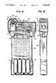
- FIG. 1Ais a partly broken-away, partly sectioned side view of a hand-held light scanning system in which a mirrorless scanner arrangement in accordance with this invention is housed;
- FIG. 1Bis an end view of FIG. 1A;
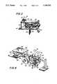
- FIG. 2is a front perspective view of the mirrorless scanner arrangement of FIG. 1A;
- FIG. 3is a partly sectioned side view of a mirrorless scanner arrangement in accordance with another embodiment of this invention.
- FIG. 4is a diagrammatic top plan view of the embodiment of FIG. 3 depicting its operation
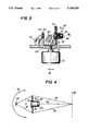
- FIG. 5is a partly sectioned side view of a mirrorless scanner arrangement in accordance with yet another embodiment of this invention.
- FIG. 6is an enlarged view taken on line 6--6 of FIG. 5;
- FIG. 7is a diagrammatic top plan view of the embodiment of FIG. 5 depicting its operation at two end-limiting positions.
- FIG. 8is a rear perspective view of the mirrorless scanner arrangement of FIG. 2 as employed in a multi-axis scanning system;
- FIG. 9is a partly broken-away perspective view of an additional embodiment of the mirrorless scanner arrangement in accordance with this invention.
- FIG. 10is a side view of a gooseneck-type scanning system workstation for use with any of the mirrorless scanner arrangements of this invention.
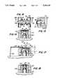
- FIG. 11is a side view of still another embodiment of a mirrorless scanner arrangement in accordance with this invention.
- FIG. 12is a sectional view taken along line 12--12 of FIG. 11;
- FIG. 13is a cross-sectional view of an alternate spring for use in the embodiment of FIGS. 11 and 12;
- FIG. 14is a sectional view taken on line 14--14 of FIG. 16;
- FIG. 15an end view of the embodiment of FIG. 16
- FIG. 16is a top plan view of an additional embodiment of a mirrorless scanner arrangement in accordance with this invention.
- FIG. 17is a view analogous to FIG. 14, but of still another embodiment of a mirrorless scanner arrangement in accordance with this invention.
- FIG. 18is a view analogous to FIG. 14, but of still another embodiment of a mirrorless scanner arrangement in accordance with this invention.
- FIG. 19is a view analogous to FIG. 14, but of yet another embodiment of a mirrorless scanner arrangement
- FIG. 20is a partly broken-away, perspective view of a hand-held scanning system for use with the mirrorless scanning arrangement.
- FIG. 21is a perspective view of a hand-held, swivel-type scanning system for use with the mirrorless scanning arrangement.
- reference numeral 10 in FIGS. 1A and 1Bgenerally identifies an arrangement in a scanner system of the type generally described in the above identified patents and patent applications, the entire contents of all of which are hereby incorporated by reference herein, for reading symbols, particularly UPC bar code symbols.
- symbolsparticularly UPC bar code symbols.
- symbolis intended to be broadly construed and to cover not only symbol patterns composed of alternating bars and spaces, but also other patterns, as well as alpha-numeric characters and, in short, any indicia having portions of different light reflectivity.
- the arrangement 10comprises a hand-held housing 12 having a base 14 which subdivides the interior of the housing into an upper half 16 and a lower half 18.
- a lightweight, high-speed, miniature scanning motor 20 similar to that described in U.S. Pat. No. 4,496,831is mounted on base 14.
- the motor 20has an output shaft 22 which is repetitively driven in alternate circumferential directions about an axis along which the shaft extends over arc lengths less than 360° in each direction.
- Structural, functional and operational aspects of the motor 20 and of control circuitry 24 for the motorare set forth in detail in U.S. Pat. No. 4,496,831 and, hence, for the sake of brevity, will not be repeated herein.
- the inventionproposes, in FIG. 1A, mounting a generally U-shaped support 26 at the end of the shaft 22, and mounting a laser/optics subassembly 28 on the support 26.
- the subassembly 28 and the support 26are jointly oscillated and turned with the shaft 22.
- the subassembly 28includes an elongated hollow tube 30, a laser diode 32 fixedly mounted at one axial end region of the tube 30, a lens barrel 34 mounted at the opposite axial end region of the tube 30, and a focusing lens 36 mounted within the barrel (see FIG. 3).
- the focusing lens 36is preferably a planoconvex lens, but may be spherical, convex or cylindrical as well.
- the barrel 34has an end wall formed with an aperture stop 38 which is an opening extending through the end wall.
- the barrel 34is mounted for longitudinal telescoping movement within and along the tube 30.
- the lens 36is situated adjacent the end wall of the barrel and is mounted for joint movement with the barrel.
- a coil spring 37(see FIG. 3) is located within and extends along the barrel and tube, and has one coil end bearing against the diode, and another coil end bearing against a planar side of the lens. The spring urges the lens against the end wall having the aperture stop, thereby fixedly locating the lens relative to the aperture stop.
- the subassembly 28includes a solid-state laser diode 32 operative for propagating and generating an incident laser beam, either in the invisible or visible light range, and the combination of a focusing lens and an aperture stop together operative for focusing the laser beam to have a beam cross-section or beam spot of a certain waist size within a range of working distances relative to the housing 12.
- the focused beampasses through the aperture stop 38 and through a scan window 40 on the housing in the vicinity of a reference plane located exteriorly of the housing within the range of working distances along an outgoing optical path.
- a portion of the light reflected off the symbolpasses along a return path through a second window 42 on the housing in the direction of arrow B to a photodetector 44 for detecting the variable intensity of the returning portion of the reflected laser light over a field of view; and for generating an electrical analog signal indicative of the detected variable light intensity.
- the photodetector 44is stationarily mounted on the printed circuit board 46.
- Printed circuit boards 48 and 50 at either side of board 46contain signal processing circuitry 52 and microprocessor control circuitry 53 for converting the analog electrical signal to a digital signal, and for processing the digital signal to data descriptive of the symbol being read. Details of the signal processing and microprocessor control circuitry can be had by reference to the above-identified patents and applications.
- a two-part multi-wire plug-in cable connector 54has one part electrically connected to the signal processing and microprocessor control circuitry and another part electrically connected to a flexible multi-wire cable 54' connected to a display 55 and a keyboard 56.
- a rechargeable battery pack 58supplies power to the laser diode and the electrical circuitry in the housing. By moving only the laser diode and the optical component relative to the stationary photodetector, power from the battery pack is conserved.
- Means for initiating readingmay advantageously include a trigger 60 mounted on the housing 12.
- the triggerextends in part outwardly of the housing to be manually actuated by a user who is holding the housing 12 in his hand.
- the triggeris operatively connected through trigger switch and actuates the laser diode 32, the motor 20, the photodetector 44, the signal processing circuitry 52 and the control circuitry 53 to initiate a reading of the symbol.
- the triggeris actuated once for each symbol to be read, each symbol in its respective turn.
- the control circuitryterminates the reading of the symbol and deactuates the previously actuated components in the housing and readies the system for the next symbol.
- FIG. 2illustrates the various electrical, mechanical and optical components assembled as a modular unit prior to mounting in the upper half 16 of the housing 12 of FIGS. 1A, 1B.
- the oscillating motor 20has an output shaft 22 on which a generally U-shaped support 26 is mounted.
- a laser/optics subassembly 28is mounted on one leg 64 of the support.
- a photodetector 44is mounted on another leg 66 of the support.
- Coiled tensile wire groups 68, 70connect the diode 32 and the photodetector 44 to the non-illustrated electrical circuitry on printed circuit board 48. Although coiled wires have been illustrated, other types of electrical connectors, e.g. flat cable, could be employed.
- a collecting lens 72is mounted on leg 64 and coaxially surrounds subassembly 28.
- the lens 72, the subassembly 28 and the photodetector 44all have a common boresight or optical axis 74 along which the optical and return paths are co-linear, and are all oscillatable as a unit in alternate circumferential directions (see double-headed arrow 76 in FIG. 4) about the axis along which shaft 22 extends.
- FIG. 4The operation of the FIG. 3 embodiment is schematically shown in FIG. 4.
- An incident laser beamis emitted from the subassembly 28. In a center position, this beam is directed along optical axis 74 to a reference plane 78 at which a symbol is located. Light is scattered in all directions from the symbol.
- a portion of the reflected light as represented by light rays 79,81,is include on collecting lens 72, e.g. a Fresnel lens, and focused onto an inlet of the photodetector 44.
- the inletmay be round, square or rectangular (see FIG. 6).
- the beam spot at the reference planelikewise moves across the symbol.
- the returning lightis always focused onto the inlet of the photodetector.
- FIG. 3 embodimentis retro-reflective because not only the incident beam, but also the field of view of the photodetector, are being simultaneously scanned across the symbol.
- FIGS. 1A, 1B embodimentis a so-called "flying spot” scanner, because only the incident beam is being swept across the symbol, the photodetector being stationary.
- the oscillating motor 20has an output shaft 22 on which a support 80 is mounted. Rather than being U-shaped like support 26, support 80 is L-shaped and has an upright leg 82.
- a laser/optics subassembly 28is mounted on leg 82.
- a photodetector 44is stationarily mounted on printed circuit board 46.
- Coiled tensile wire group 68interconnects the diode 32 and electrical circuitry on board 46.
- Collecting lens 72is mounted on leg 82 in a coaxially surrounding relationship with subassembly 28. The lens 72 and the subassembly 28 turn as a unit in either direction of double-headed arrow 76, whereas photodetector 44, in contrast to the previous embodiment of FIG. 3, is stationary.
- an incident light beam emitted from subassembly 28is directed in one end-limiting position along optical axis 84 to impinge on a symbol located at the reference plane 78, whereupon a portion of the reflected light, as represented by light rays 86, 88, is incident on collecting lens 72 and focused at one end 90 of an elongated slotlike inlet 92 of the photodetector 44, best shown in FIG. 6.
- the collected portion of reflected lightis focused at an opposite end 94 of the inlet 92.
- the collected, focused lighttravels lengthwise along the inlet 92.
- FIGS. 5-7 embodimentis another retroreflective arrangement, because both the incident beam is being swept across the symbol, and the field of view of the photodetector is likewise being swept across the symbol at the same time due to the movement of the collecting lens.
- the collecting lenscould be eliminated by having the output power of the light source sufficiently high.
- FIG. 8shows an arrangement for generating a scan pattern extending in more than one direction over the symbol.
- motor 20repetitively drives output shaft 22, support 26 and laser/optics subassembly 28 in the alternate directions indicated by arrows 76.
- Tensile wire group 68interconnects the diode 32 with a low voltage power supply 96.
- the motor and its superstructureare mounted on a horizontal platform 98 of a base 100.
- the basehas additional platforms for other components.
- horizontal platform 102supports a collecting lens 104.
- Platform 106supports a photodetector 44 on an upper surface, as well as a printed circuit board 108 on which signal processing circuitry is mounted on a lower surface.
- a second motor 20' identical to motor 20is mounted on a vertical platform 110 and has an output shaft 22' which is at right angles to shaft 22.
- a planar mirror 112is mounted at one end of shaft 22', thereby being similar to the scanning element described in U.S. Pat. No. 4,496,831.
- the motor 22'drives the mirror 112 in alternate circumferential directions as indicated by double-headed arrow 114.
- FIG. 9shows an arrangement wherein the wire joints between the diode and its power supply are positioned in the immediate vicinity of the shaft, thereby minimizing the stress forces acting to weaken such joints and maximizing the working lifetime of the arrangement.
- a support block 26"is mounted on the shaft 22, but off to one side of the shaft.
- the subassembly 28is mounted on the block 26".
- a printed circuit board 116is mounted at the side of the block facing the shaft 22.
- the board 116has three printed conductive strips 118a, 118b, 118c extending along the board 116.
- the laser diode 32has a first group of wires 68 connected to respective ends of the strips; and a second group of wires 120 is connected to respective opposite ends of the strips and to the power supply 96.
- the subassembly 28, the board 116 and the first group of wires 68are jointly oscillated.
- the second group of wires 120is subjected to stress forces, but, as shown, the wire joints at the opposite ends of the strips are immediately adjacent the shaft 22 so that the magnitude of the stress forces is much reduced as compared to the situation wherein the first group of wires 68 were directly connected to the power supply 96.
- FIG. 10shows a desk-top workstation wherein a housing 121 generally having the same shape as the upper half of housing 12 in FIG. 1A is mounted above a base 123 situated on a generally horizontal support surface such as a tabletop 125.
- a gooseneck-type semirigid, bendable, conduit 127interconnects the housing 121 with the base 123 and enables the housing to be manually bendably positioned in any desired orientation relative to the base and to be maintained in the desired orientation.
- the light beam emitted from the housingcan thus be positioned at any desired angle relative to the symbol to be read.
- the base 123is hollow and contains signal processing circuitry which is connected by electrical wires running through the conduit 127 to the mirror scanning arrangement contained in the housing 121.
- the end of the conduit remote from the housing 121could be attached to a cash register, analogous point-of-sale apparatus, or a fixed mount, e.g. on a production line.
- the laser diode/optics subassembly 28 by itself or with the photodetector 44is turned about an axis to effect a scanning or sweeping action.
- This inventionalso proposes moving the focusing lens 36 either by itself or with the aperture stop 28 relative to the diode 32 in a plane generally parallel to the light-emitting outlet of the diode.
- the laser diode 32is stationarily mounted on a support 122.
- the diode 32emits along optical axis 130 a wide-angle fan-shaped laser beam schematically represented by light rays 124, 126.
- the fan-shaped beamdiverges at different angles in both orthogonal planes extending parallel to the plane of the diode outlet and perpendicular to the optical axis 130.
- the focusing lens 36is mounted in a holder 128 at a fixed distance of focal length F as measured along axis 130, from the diode.
- the holderhas an opening centered on the axis 130, the opening serving as the aperture stop 38.
- a voice coil 138surrounds the holder 128 inside the casing 132 and is bounded by north N and south S poles of the casing.
- the holder and, in turn, the lens and the aperture stopare made to jointly reciprocate back and forth in a plane perpendicular to axis 130 due to electromagnetic attraction and repulsion forces generated at the coil.
- Dthe deflection of the lens and aperture stop as measured from the axis 130 to one end-limiting position
- FIG. 13shows an alternate to the convoluted springs 134, 136.
- a so-called “spider” spring 142 having curved legs 144could also be used.
- FIG. 14shows another arrangement for reciprocally shifting the lens 36 and aperture stop 38 in a plane parallel to the plane of the outlet of the diode 32.
- the lens 36is mounted on a bridge support 150 which spans the distance between, and is carried by, two center legs 152, 154 of E-shaped leaf springs 156, 158.
- Outer legs 160, 162 of spring 156 and outer legs 164, 166 of spring 158are stationarily connected to an overhead support frame 170.
- the bridge support 150has an opening centered on optical axis 130, the opening serving as the aperture stop 38.
- a permanent magnet strip 172having a north N pole at one end and a south S pole at an opposite end is carried by the bridge support.
- a pair of driving coils 174, 176surrounds each pole.
- each driving coilis electrically energized. Electromagnetic attraction and repulsion forces are generated by magnetic interaction between the coils and the poles N, S, thereby causing the bridge support to be reciprocally shifted in a plane perpendicular to axis 130.
- FIG. 14shows this arrangement in a center, non-shifted position.
- FIG. 17 embodiment described belowillustrates a shifted position. It will be noted that only the upper ends of the center legs of the E-springs are displaced. A substantially constant distance between the lens and aperture stop combination and the diode is maintained. Proper laser beam focus at the reference plane is thus maintained thereat.
- the shifting of the lens and aperture stopcauses the laser beam emitted by the diode to be deflected at an angle ##EQU2##
- the beam spotis moved along an arc around a center of curvature at the lens. It is possible, by having unequal lengths or stiffnesses in the legs of the springs, to have the beam spot moved in a desired manner across the symbol. For example, the spot can be moved in a straight line.
- FIG. 17shows an arrangement identical to FIG. 14, but, instead of the magnetic strip 172, a plate 180 is connected to the bridge support.
- the plate 180has a lug 182 to which a drive bar 184 is pivotably connected.
- the bar 184can be connected to a pure mechanical drive, an electro-mechanical drive, or a piezo-electric substrate. i.e., a transducer operative for converting electrical to mechanical energy, to effect the reciprocal movement.
- the center legs 152, 154 of the springscan be made of one bi-metallic material while the outer legs are made of another bi-metallic material. Heating all the legs would cause the center legs to be displaced relative to the outer legs.
- FIG. 18Another approach is shown in FIG. 18, wherein the aperture stop 38 is held stationary, and only the focusing lens 36 is reciprocally shifted. Since the laser beam does not pass through the center of the lens 36 when the lens is shifted off axis, the deflection or scan angle A is amplified. Light passing through the lens off the axis 130 has more optical aberrations, but they have not been found to be significant for bar code reading applications.
- the low mass of the moving structurei.e. the lens alone; the lens and aperture stop together; the lens, aperture stop and diode jointly; and the lens, aperture stop, diode and photodetector jointly, enables the system to operate at resonance for low power applications, as well as off resonance. Very high scanning speeds on the order of 40 scans per second and more are obtainable due to the low mass of the moving structure.
- FIG. 19Yet another approach is shown in FIG. 19, wherein the focusing lens 36 is held stationary, and only the aperture stop 38 is reciprocally shifted.
- the aperture stop 38is formed as an opening in a top wall 200 that is positioned by side walls 202, 204 at a distance from a support 206 on which the laser diode 32 is mounted.
- the apertured top wall 200is shiftable to the left and to the right, as indicated by the phantom lines, by any reciprocating drive, e.g. an electromagnet or piezo-electric drive.
- Bimorph materialcan also be used for the walls 200, 202, 204 to move the aperture stop in a plane in front of the lens 36.
- FIG. 20shows the compact laser/optics subassembly 28 mounted on the reciprocating motor 20, as described above, installed in a hand-held housing 210 equipped with a display 212 and a keyboard 214.
- the housing 210has a rectangular cross-section and, at its top, is provided with a superstructure that enables scanning to be performed to the right or, in another mode of operation, to the left of the housing.
- the housing 210has a top rectangular wall 216 fixedly mounted in place with the aid of four screws 218 at the corners of the top wall.
- a hood 220is mounted at one end of the top wall.
- a stationary reflecting mirror 222is located within the confines of the hood above the top wall 216.
- a scan window 224closes the interior of the hood from the environment.
- the mirror 222is positioned in the path of the emitted laser beam emanating from the laser/optics subassembly 28, and redirects the laser beam toward one side, e.g. toward the right side, of the housing. Returning light from the symbol being read passes through the window 224 and is collected by photodetector 44.
- the scanning arrangementwill work just as described above, except that, this time, the mirror 222 will redirect the laser beam toward the other side, e.g. toward the left side, of the housing. In this way, right- and left-handed users can be accommodated.
- a housing 226 of cylindrical cross-sectionhas a circular top wall 228 on which a hood 230 is supported.
- a reflecting mirror identical to mirror 222is mounted within hood 230.
- a scan window 232closes the hood 230.
- An L-shaped locking lug 234depends from the top wall 228 and, in the illustrated position, lockingly engages a hook 236 provided on the circular side wall of the housing 226.
- the same laser/optics subassembly shown in FIG. 20is mounted within housing 226. The laser beam is propagated toward the right in FIG. 21.
- top wall 228 and hood 230can be turned to the position shown in phantom lines until the lug 234 engages another non-illustrated hook spaced 180° away from hook 236. In this locked position, the laser beam is propagated toward the left in FIG. 21.
- the swiveling of a locking lug to engage one or the other of two hooks with a snap-type actionis somewhat easier to perform than the removal and replacement of screws as described for FIG. 20.
- the mirrorless scanning arrangementis very compact in size. This allows the arrangement to be fabricated as a module that can be installed in many different types of laser scanning systems.
- the moduleadvantageously comprises a laser/optics subassembly mounted on a support such as a reciprocating scan component, together with a photodetector, all of which are connected to an electrical connector to enable the module to be electrically connected to other electrical components.
Landscapes
- Physics & Mathematics (AREA)
- Electromagnetism (AREA)
- Engineering & Computer Science (AREA)
- Health & Medical Sciences (AREA)
- General Health & Medical Sciences (AREA)
- Toxicology (AREA)
- Artificial Intelligence (AREA)
- Computer Vision & Pattern Recognition (AREA)
- General Physics & Mathematics (AREA)
- Theoretical Computer Science (AREA)
- Mechanical Optical Scanning Systems (AREA)
Abstract
Description
Claims (45)
Priority Applications (38)
| Application Number | Priority Date | Filing Date | Title |
|---|---|---|---|
| US07/193,265US5144120A (en) | 1988-05-11 | 1988-05-11 | Mirrorless scanners with movable laser, optical and sensor components |
| JP1111938AJPH0738208B2 (en) | 1988-05-11 | 1989-04-28 | Mirrorless scanner with movable laser element, optical element and sensor element |
| CA000598672ACA1327850C (en) | 1988-05-11 | 1989-05-04 | Mirrorless scanners with movable laser, optical and sensor components |
| EP89108500AEP0341717B1 (en) | 1988-05-11 | 1989-05-11 | Mirrorless scanner with movable laser and optical components |
| EP04075162AEP1429278B1 (en) | 1988-05-11 | 1989-05-11 | Mirrorless optical scanner arrangement |
| DE68929559TDE68929559D1 (en) | 1988-05-11 | 1989-05-11 | Mirrorless optical scanning system |
| EP96201913AEP0741367A3 (en) | 1988-05-11 | 1989-05-11 | Optical scanner |
| DE68929519TDE68929519T2 (en) | 1988-05-11 | 1989-05-11 | Mirrorless scanner with moving laser, optical and sensing components |
| DE68928186TDE68928186T2 (en) | 1988-05-11 | 1989-05-11 | Mirror-free scanner with movable laser source and movable, optical components |
| EP93120433AEP0595371B1 (en) | 1988-05-11 | 1989-05-11 | Bar code reader with adjustable scan head |
| EP95117822AEP0702317A3 (en) | 1988-05-11 | 1989-05-11 | Mirrorless scanner with movable laser |
| EP96202253AEP0742530B1 (en) | 1988-05-11 | 1989-05-11 | Mirrorless scanners with movable laser, optical and sensor components |
| DE68929254TDE68929254T2 (en) | 1988-05-11 | 1989-05-11 | Barcode reader with adjustable readhead |
| US07/699,417US5191197A (en) | 1988-05-11 | 1991-05-13 | Arm mounted scanner actuatable by hand movement |
| US07/766,315US5170277A (en) | 1988-05-11 | 1991-09-27 | Piezoelectric beam deflector |
| US07/823,588US5254844A (en) | 1988-05-11 | 1992-01-17 | Mirrorless scanners with movable laser, optical and sensor components |
| US07/881,280US5306900A (en) | 1988-05-11 | 1992-05-11 | Hand held bar code scanner with adjustment of direction of emitted light beam |
| US07/897,837US5250790A (en) | 1988-05-11 | 1992-06-12 | Hand-mounted scanner with automatic manual initiation of reading indicia |
| US07/897,664US5374817A (en) | 1988-05-11 | 1992-06-12 | Pre-objective scanner with flexible optical support |
| US08/065,304US5412193A (en) | 1988-05-11 | 1993-05-24 | Mobile point-of-sale supermarket checkout system |
| US08/092,851US5367152A (en) | 1988-05-11 | 1993-07-19 | Method of reading indicia from either side of scanner housing |
| US08/153,443US5471042A (en) | 1988-05-11 | 1993-11-17 | Handheld data entry terminal having dual trigger switches |
| US08/181,925US5401948A (en) | 1988-05-11 | 1994-01-14 | Mirrorless scanners with movable laser, optical and sensor components |
| US08/218,959US5536925A (en) | 1988-05-11 | 1994-03-28 | Optical scanner with scanning light beam and detector field of view |
| US08/246,382US5410140A (en) | 1988-05-11 | 1994-05-20 | Mirrorless ring mounted miniature optical scanner |
| US08/366,383US5479002A (en) | 1988-05-11 | 1994-12-29 | Bar code scanner with scanning beam and/or field of view adjustable about three mutually orthogonal axes |
| US08/400,616US5525791A (en) | 1988-05-11 | 1995-03-08 | Mirrorless scanners with movable laser, optical and sensor components |
| US08/409,913US5514861A (en) | 1988-05-11 | 1995-03-23 | Computer and/or scanner system mounted on a glove |
| US08/416,128US5578810A (en) | 1988-05-11 | 1995-04-03 | Ring mounted miniature optical scanner |
| US08/460,875US5565671A (en) | 1988-05-11 | 1995-06-05 | Handheld data entry terminal having dual trigger switches |
| US08/592,071US5583332A (en) | 1988-05-11 | 1996-01-26 | Compact scan module with oscillatable unitary assembly |
| US08/597,882US5661290A (en) | 1988-05-11 | 1996-02-07 | Scanner with flexibly supported light emitter |
| US08/727,782US5798512A (en) | 1988-05-11 | 1996-10-08 | Hand-held terminal with movable window |
| US08/800,610US5811773A (en) | 1988-05-11 | 1997-02-14 | Scanner with flexible flat cable electrically connected to light emitter |
| US08/807,286US5744788A (en) | 1988-05-11 | 1997-02-27 | Voice-activated optical scanning system |
| US08/889,765US5969327A (en) | 1988-05-11 | 1997-07-08 | Arm-mounted reader with object sensing |
| US09/036,385US5907145A (en) | 1988-05-11 | 1998-03-06 | Hand-held terminal with reciprocally oscillating laser |
| US10/053,258US6688526B2 (en) | 1988-05-11 | 2002-01-18 | Bar code reader with a clip for being worn and supported by a user |
Applications Claiming Priority (1)
| Application Number | Priority Date | Filing Date | Title |
|---|---|---|---|
| US07/193,265US5144120A (en) | 1988-05-11 | 1988-05-11 | Mirrorless scanners with movable laser, optical and sensor components |
Related Child Applications (3)
| Application Number | Title | Priority Date | Filing Date |
|---|---|---|---|
| US62661290AContinuation | 1988-05-11 | 1990-12-07 | |
| US07/699,417Continuation-In-PartUS5191197A (en) | 1988-05-11 | 1991-05-13 | Arm mounted scanner actuatable by hand movement |
| US07/881,280Continuation-In-PartUS5306900A (en) | 1988-05-11 | 1992-05-11 | Hand held bar code scanner with adjustment of direction of emitted light beam |
Publications (1)
| Publication Number | Publication Date |
|---|---|
| US5144120Atrue US5144120A (en) | 1992-09-01 |
Family
ID=22712906
Family Applications (1)
| Application Number | Title | Priority Date | Filing Date |
|---|---|---|---|
| US07/193,265Expired - LifetimeUS5144120A (en) | 1988-05-11 | 1988-05-11 | Mirrorless scanners with movable laser, optical and sensor components |
Country Status (5)
| Country | Link |
|---|---|
| US (1) | US5144120A (en) |
| EP (6) | EP0595371B1 (en) |
| JP (1) | JPH0738208B2 (en) |
| CA (1) | CA1327850C (en) |
| DE (4) | DE68928186T2 (en) |
Cited By (69)
| Publication number | Priority date | Publication date | Assignee | Title |
|---|---|---|---|---|
| EP0467014A2 (en) | 1990-07-16 | 1992-01-22 | Symbol Technologies, Inc. | Arrangement and method for a point-of sale site |
| USD338002S (en) | 1991-11-18 | 1993-08-03 | A. C. Nielsen Company | Scanner |
| US5303080A (en)* | 1993-04-01 | 1994-04-12 | Eastman Kodak Company | Beam scanning system including actively-controlled optical head |
| US5306900A (en)* | 1988-05-11 | 1994-04-26 | Symbol Technologies, Inc. | Hand held bar code scanner with adjustment of direction of emitted light beam |
| WO1994014136A1 (en)* | 1992-12-04 | 1994-06-23 | Psc, Inc. | Optical symbol (bar code) reading systems and devices |
| US5371347A (en)* | 1991-10-15 | 1994-12-06 | Gap Technologies, Incorporated | Electro-optical scanning system with gyrating scan head |
| USD355904S (en) | 1993-10-25 | 1995-02-28 | Symbol Technologies, Inc. | Optical scanner |
| US5401948A (en)* | 1988-05-11 | 1995-03-28 | Symbol Technologies, Inc. | Mirrorless scanners with movable laser, optical and sensor components |
| US5404001A (en)* | 1992-10-08 | 1995-04-04 | Bard; Simon | Fiber optic barcode reader |
| US5410140A (en)* | 1988-05-11 | 1995-04-25 | Symbol Technologies, Inc. | Mirrorless ring mounted miniature optical scanner |
| US5416310A (en)* | 1993-05-28 | 1995-05-16 | Symbol Technologies, Inc. | Computer and/or scanner system incorporated into a garment |
| US5422469A (en)* | 1989-10-30 | 1995-06-06 | Symbol Technologies, Inc. | Fiber optic barcode readers using purely mechanical scanner oscillation |
| US5422472A (en)* | 1992-12-04 | 1995-06-06 | Psc, Inc. | Optical symbol (bar code) reading systems having an electro-optic receptor with embedded grating rings |
| US5471042A (en)* | 1988-05-11 | 1995-11-28 | Symbol Technologies, Inc. | Handheld data entry terminal having dual trigger switches |
| US5479001A (en)* | 1994-07-22 | 1995-12-26 | Khyber Technologies Corporation | Right- and left-handed operable, grip-held pen computing device with removable data entry modules |
| US5479002A (en)* | 1988-05-11 | 1995-12-26 | Symbol Technologies, Inc. | Bar code scanner with scanning beam and/or field of view adjustable about three mutually orthogonal axes |
| US5491651A (en)* | 1992-05-15 | 1996-02-13 | Key, Idea Development | Flexible wearable computer |
| US5506394A (en)* | 1990-11-15 | 1996-04-09 | Gap Technologies, Inc. | Light beam scanning pen, scan module for the device and method of utilization |
| US5514861A (en)* | 1988-05-11 | 1996-05-07 | Symbol Technologies, Inc. | Computer and/or scanner system mounted on a glove |
| US5539194A (en)* | 1989-06-07 | 1996-07-23 | Norand Corporation | Modular hand-held data entry system |
| US5555490A (en)* | 1993-12-13 | 1996-09-10 | Key Idea Development, L.L.C. | Wearable personal computer system |
| US5572401A (en)* | 1993-12-13 | 1996-11-05 | Key Idea Development L.L.C. | Wearable personal computer system having flexible battery forming casing of the system |
| US5593139A (en)* | 1994-11-08 | 1997-01-14 | Julian; Samuel | Device for connecting a winch to a box hitch |
| US5602377A (en)* | 1995-03-01 | 1997-02-11 | Metanetics Corporation | Bar code dataform scanning and labeling apparatus and method |
| US5610387A (en)* | 1992-05-15 | 1997-03-11 | Symbol Technologies, Inc. | Portable optical scanning system worn by a user for reading indicia of differing light reflectivity |
| US5635700A (en)* | 1994-07-27 | 1997-06-03 | Symbol Technologies, Inc. | Bar code scanner with multi-channel light collection |
| US5750975A (en)* | 1995-08-25 | 1998-05-12 | Teletransactions, Inc. | Hand held bar code dataform reader having a rotatable reading assembly |
| US5767502A (en)* | 1994-10-31 | 1998-06-16 | Psc, Inc. | Grip-conforming trigger mechanism for a hand-held bar code scanner |
| US5796088A (en)* | 1995-08-15 | 1998-08-18 | Teletransactions, Inc. | Hand held portable bar code dataform reader having a rotatable reader module portion |
| US5816689A (en)* | 1996-07-22 | 1998-10-06 | Strazzabosco; Frank | Apparatus and associated method for creating a broad area of illumination |
| US5825617A (en)* | 1992-10-02 | 1998-10-20 | Teletransactions, Inc. | Workslate computer having modular device docking stations on horizontal and vertical side portions |
| US5837989A (en)* | 1991-09-17 | 1998-11-17 | Metrologic Instruments, Inc. | Portable data collection device for collecting and transmitting bar code symbol character data |
| US5866894A (en)* | 1988-10-21 | 1999-02-02 | Symbol Technologies, Inc. | Electro-optical scanner module having oscillating lens |
| US5874721A (en)* | 1990-09-11 | 1999-02-23 | Metrologic Instruments, Inc. | Body wearable laser scanning system with programmed mode of automatic code symbol reading for consecutively reading bar code symbols without scanner reactivation |
| US5920060A (en)* | 1995-09-21 | 1999-07-06 | Symbol Technologies, Inc. | Bar code scanner with simplified auto-focus capablilty |
| US5959283A (en)* | 1996-02-20 | 1999-09-28 | Opticon, Inc. | Optical pattern reading apparatus with movable optical unit |
| US5979760A (en)* | 1997-06-27 | 1999-11-09 | Accu-Sort Systems, Inc. | Scanner with linear actuator based lens positioning system |
| US5979764A (en)* | 1996-07-22 | 1999-11-09 | Symbol Technologies, Inc. | Hand-held electronic apparatus with pivoting display |
| US6000619A (en)* | 1992-02-21 | 1999-12-14 | Spectra-Physics Scanning Systems, Inc. | Scanner assembly |
| US6015090A (en)* | 1992-06-12 | 2000-01-18 | Symbol Technologies, Inc. | Hand mountable adaptive barcode scanner |
| US6024283A (en)* | 1995-02-27 | 2000-02-15 | Symbol Technologies, Inc. | Bar code readers having selectable optical elements |
| US6039258A (en)* | 1996-07-18 | 2000-03-21 | Norand Corporation | Hand-held portable data collection terminal system |
| US6059188A (en)* | 1993-10-25 | 2000-05-09 | Symbol Technologies | Packaged mirror including mirror travel stops |
| US6065676A (en)* | 1992-04-17 | 2000-05-23 | Psc Scanning, Inc. | Ultra-compact bar-code scanner |
| US6092728A (en)* | 1992-03-30 | 2000-07-25 | Symbol Technologies, Inc. | Miniature laser diode focusing module using micro-optics |
| US6097607A (en)* | 1996-11-01 | 2000-08-01 | Via, Inc. | Flexible computer system |
| US6098886A (en)* | 1998-01-21 | 2000-08-08 | Symbol Technologies, Inc. | Glove-mounted system for reading bar code symbols |
| US6142378A (en)* | 1994-10-27 | 2000-11-07 | Fujitsu Limited | Replaceable emission-condensing unit for a bar code reader |
| US6215475B1 (en) | 1992-10-02 | 2001-04-10 | Telxon Corporation | Highly integrated portable electronic work slate unit |
| US6260763B1 (en) | 1996-02-06 | 2001-07-17 | Psc Scanning, Inc. | Integral illumination source/collection lens assembly for data reading system |
| US6266045B1 (en) | 1994-06-30 | 2001-07-24 | Telxon Corporation | Interactive display user interface computer and method |
| US20020000470A1 (en)* | 1993-05-28 | 2002-01-03 | Michael Lanzaro | Portable data collection system |
| US6338432B1 (en)* | 1997-02-19 | 2002-01-15 | Opticon Inc | Optical pattern reading apparatus with movable optical unit |
| US6390370B1 (en) | 1990-11-15 | 2002-05-21 | Symbol Technologies, Inc. | Light beam scanning pen, scan module for the device and method of utilization |
| USD460068S1 (en) | 2000-03-27 | 2002-07-09 | Symbol Technologies, Inc. | Portable handheld terminal housing |
| US6497193B2 (en) | 1999-06-07 | 2002-12-24 | Neocera, Inc. | Scanned focus deposition system |
| US6622916B1 (en)* | 1999-05-03 | 2003-09-23 | James S. Bianco | Optical indicia scanner and method of use |
| US20040136069A1 (en)* | 1992-03-30 | 2004-07-15 | Symbol Technologies, Inc., A Delaware Corporation | Athermalized plastic lens |
| US6853293B2 (en) | 1993-05-28 | 2005-02-08 | Symbol Technologies, Inc. | Wearable communication system |
| US20060043304A1 (en)* | 2004-08-31 | 2006-03-02 | Battelle Memorial Institute | Apparatus and method for osl-based, remote radiation monitoring and spectrometry |
| US7017815B2 (en) | 2001-05-01 | 2006-03-28 | Symbol Technologies, Inc. | Compact externally-driven scanner |
| US7116697B1 (en)* | 1995-04-03 | 2006-10-03 | Black & Decker Inc. | Laser level |
| US20070083443A1 (en)* | 2002-12-23 | 2007-04-12 | System Applications Engineering, Inc | Object loading system and method |
| US20070108282A1 (en)* | 2005-11-16 | 2007-05-17 | Microvision, Inc. | System and method for image detection using large area pin diode |
| EP1906294A2 (en) | 1999-05-03 | 2008-04-02 | Symbol Technologies, Inc. | Wearable communication system |
| US8038538B2 (en) | 2004-06-04 | 2011-10-18 | Mattel, Inc. | Electronic device for enhancing an interactive experience with a tangible medium of expression |
| US8336780B1 (en) | 2010-06-15 | 2012-12-25 | Webscan, Inc. | Windowed housing with rotatable imaging device |
| US8570629B2 (en) | 2011-09-23 | 2013-10-29 | Steve Spears | Reciprocating laser scanning device |
| US11022421B2 (en) | 2016-01-20 | 2021-06-01 | Lucent Medical Systems, Inc. | Low-frequency electromagnetic tracking |
Families Citing this family (25)
| Publication number | Priority date | Publication date | Assignee | Title |
|---|---|---|---|---|
| US6340115B1 (en) | 1987-12-28 | 2002-01-22 | Symbol Technologies, Inc. | Card reader and method for completing transactions |
| US6937998B1 (en) | 1987-12-28 | 2005-08-30 | Symbol Technologies, Inc. | Arrangement for and method of expediting transactions based on a customer's proximity to the transactions |
| US5448046A (en) | 1987-12-28 | 1995-09-05 | Symbol Technologies, Inc. | Arrangement for and method of expediting commercial product transactions at a point-of-sale site |
| US5374817A (en)* | 1988-05-11 | 1994-12-20 | Symbol Technologies, Inc. | Pre-objective scanner with flexible optical support |
| US5168149A (en)* | 1989-10-30 | 1992-12-01 | Symbol Technologies, Inc. | Scan pattern generators for bar code symbol readers |
| US5280165A (en)* | 1989-10-30 | 1994-01-18 | Symbol Technolgoies, Inc. | Scan pattern generators for bar code symbol readers |
| US6332575B1 (en) | 1997-10-31 | 2001-12-25 | Symbol Technologies, Inc. | Audible indicators for optical code reading systems |
| US6330973B1 (en)* | 1989-10-30 | 2001-12-18 | Symbol Technologies, Inc. | Integrated code reading systems including tunnel scanners |
| US5367151A (en)* | 1989-10-30 | 1994-11-22 | Symbol Technologies, Inc. | Slim scan module with interchangeable scan element |
| JPH03100960U (en)* | 1990-01-30 | 1991-10-22 | ||
| JP2731015B2 (en)* | 1990-03-13 | 1998-03-25 | 富士通株式会社 | Read head position control mechanism |
| EP0809204B1 (en)* | 1990-05-08 | 2003-03-19 | Symbol Technologies, Inc. | Scanning arrangement |
| AU643026B2 (en)* | 1990-06-15 | 1993-11-04 | Nippondenso Co. Ltd. | Information reader |
| US5115120A (en)* | 1990-06-26 | 1992-05-19 | Photographic Sciences Corporation | Scan modules for bar code readers and in which scan elements are flexurally supported |
| JP2798489B2 (en)* | 1990-08-16 | 1998-09-17 | 富士通株式会社 | Mobile terminal device |
| NL9100129A (en)* | 1991-01-25 | 1992-08-17 | Opticon Sensors Europ | MECHANICAL COUPLING FOR SYMBOL CODE SCANNERS. |
| CA2080784C (en)* | 1991-11-04 | 2003-08-19 | Simon Bard | Compact bar code scanning arrangement |
| US5616906A (en)* | 1993-07-23 | 1997-04-01 | Khyber Technologies Corporation | Grip held and grip operable data entry device |
| US5925873A (en)* | 1993-07-23 | 1999-07-20 | Khyber Technologies Corporation | Grip held and grip operable data entry device |
| NL1003957C2 (en) | 1996-02-26 | 1997-08-27 | Scantech Bv | Device for scanning barcodes. |
| IT1289438B1 (en)* | 1996-12-11 | 1998-10-15 | Datalogic Spa | SCANNING READER OF AN OPTICAL CODE PLACED ON A MOVING ARTICLE AND METHOD OF SCANNING OF SAID OPTICAL CODE BY MEANS OF SAID |
| CN100395768C (en)* | 1998-10-30 | 2008-06-18 | 讯宝科技公司 | Improved integrated code reading system including tunnel scanner |
| JP5035657B2 (en)* | 2005-12-28 | 2012-09-26 | 株式会社ニコン | Encoder and laser irradiation device |
| JP5182702B2 (en)* | 2008-09-30 | 2013-04-17 | Necインフロンティア株式会社 | Bar code reader with counting function and counting method in bar code reader |
| DE102021127370A1 (en) | 2021-10-21 | 2023-04-27 | Wacker Neuson Produktion GmbH & Co. KG | Remote control for a self-propelled implement |
Citations (16)
| Publication number | Priority date | Publication date | Assignee | Title |
|---|---|---|---|---|
| US2039406A (en)* | 1931-01-02 | 1936-05-05 | Elmer L Greensfelder | Method of and apparatus for operating intelligence systems |
| US3585366A (en)* | 1968-09-19 | 1971-06-15 | Monarch Marking Systems Inc | Self-timing encoded tag reader |
| US3729618A (en)* | 1972-06-12 | 1973-04-24 | Ibm | Scanning mechanism and printer |
| US3781078A (en)* | 1971-12-20 | 1973-12-25 | E Wildhaber | Optical scanner with laser |
| US3866056A (en)* | 1973-12-17 | 1975-02-11 | Monarch Marking Systems Inc | Scanning apparatus |
| JPS5232698A (en)* | 1975-09-08 | 1977-03-12 | Toshiba Corp | Laser light scanning equipment |
| US4251798A (en)* | 1978-05-31 | 1981-02-17 | Symbol Technologies | Portable laser scanning arrangement for and method of evaluating and validating bar code symbols |
| US4369361A (en)* | 1980-03-25 | 1983-01-18 | Symbol Technologies, Inc. | Portable, stand-alone, desk-top laser scanning workstation for intelligent data acquisition terminal and method of scanning |
| US4387297A (en)* | 1980-02-29 | 1983-06-07 | Symbol Technologies, Inc. | Portable laser scanning system and scanning methods |
| US4409470A (en)* | 1982-01-25 | 1983-10-11 | Symbol Technologies, Inc. | Narrow-bodied, single-and twin-windowed portable laser scanning head for reading bar code symbols |
| US4410235A (en)* | 1979-09-10 | 1983-10-18 | Siemens Aktiengesellschaft | Device for producing a moving light beam |
| US4436260A (en)* | 1981-12-21 | 1984-03-13 | The United States Of America As Represented By The Secretary Of The Air Force | Optical scanner for use in confined areas |
| US4578571A (en)* | 1983-11-14 | 1986-03-25 | Numa Corporation | Portable bar code scanning device and method |
| US4766297A (en)* | 1987-01-08 | 1988-08-23 | Recognition Equipment Incorporated | Dual mode stationary and portable scanning system |
| US4838632A (en)* | 1988-05-06 | 1989-06-13 | Lumisys Inc. | Two-dimensional beam scanner |
| US4999617A (en)* | 1985-10-24 | 1991-03-12 | Sharp Kabushiki Kaisha | Device for reading patterns displayed on a display unit |
Family Cites Families (29)
| Publication number | Priority date | Publication date | Assignee | Title |
|---|---|---|---|---|
| US2392447A (en)* | 1943-08-21 | 1946-01-08 | Detroit Res Lab Inc | Lighting fixture |
| JPS5919386B2 (en)* | 1977-12-01 | 1984-05-04 | 富士通株式会社 | information reading device |
| US4360798A (en) | 1978-05-31 | 1982-11-23 | Symbol Technologies, Inc. | Portable laser scanning arrangement for and method of evaluating and validating bar code symbols |
| US4593186A (en) | 1980-02-29 | 1986-06-03 | Symbol Technologies, Inc. | Portable laser scanning system and scanning methods |
| US4496831A (en) | 1980-02-29 | 1985-01-29 | Symbol Technologies, Inc. | Portable laser scanning system and scanning methods |
| JPS5785119A (en)* | 1980-11-18 | 1982-05-27 | Nec Corp | Desk lamp display device |
| JPS5829267A (en)* | 1981-08-13 | 1983-02-21 | Yokogawa Hokushin Electric Corp | Optical scanner |
| US4736095A (en) | 1982-01-25 | 1988-04-05 | Symbol Technologies, Inc. | Narrow-bodied, single- and twin-windowed portable laser scanning head for reading bar code symbols |
| US4845350B1 (en) | 1982-01-25 | 1991-04-30 | Narrow-bodied,single-and twin-windowed portable laser scanning head for reading bar code symbols | |
| US4758717A (en) | 1982-01-25 | 1988-07-19 | Symbol Technologies, Inc. | Narrow-bodied, single-and twin-windowed portable laser scanning head for reading bar code symbols |
| US4460120A (en) | 1982-01-25 | 1984-07-17 | Symbol Technologies, Inc. | Narrow bodied, single- and twin-windowed portable laser scanning head for reading bar code symbols |
| DE3220016A1 (en)* | 1982-05-27 | 1983-12-01 | Dorner, Jörg, Dr.-Ing., 8000 München | DEVICE FOR PRODUCING AN OPTICAL OR ELECTRONICALLY OR MAGNETICALLY STORED IMAGE INFORMATION OF AN ESSENTIAL AREA |
| US4560862A (en)* | 1983-04-26 | 1985-12-24 | Skan-A-Matic Corp. | System for optical scanning over a large depth of field |
| DE3342038C1 (en) | 1983-11-22 | 1985-03-07 | Erhardt & Leimer GmbH, 8900 Augsburg | Device for the detection of markings on moving marking carriers |
| US4607156A (en) | 1984-03-26 | 1986-08-19 | Symbol Technologies, Inc. | Shock-resistant support structure for use in portable laser scanning heads |
| JPS60222979A (en)* | 1984-04-19 | 1985-11-07 | Toshiba Corp | Information reader |
| DE3687127T2 (en)* | 1985-02-28 | 1993-05-06 | Symbol Technologies Inc | PORTABLE SCAN HEAD WITH A LASER DIODE. |
| GB2177788A (en)* | 1985-07-20 | 1987-01-28 | Michael Alan Roy Atkins | Electric lighting devices having flexible supports |
| US4621189A (en) | 1985-10-08 | 1986-11-04 | Telxon Corporation | Hand held data entry apparatus |
| US4691212A (en)* | 1985-11-14 | 1987-09-01 | Xerox Corporation | Piezoelectric optical beam deflector |
| DE3625917A1 (en)* | 1986-05-07 | 1987-11-12 | Techno Polymer Hans J Kuhl | Table lamp |
| US5059778A (en)* | 1986-09-29 | 1991-10-22 | Mars Incorporated | Portable data scanner apparatus |
| CA1294045C (en)* | 1986-10-24 | 1992-01-07 | Mitsuru Nishikawa | Optical code reading device |
| US4816661A (en) | 1986-12-22 | 1989-03-28 | Symbol Technologies, Inc. | Scan pattern generators for bar code symbol readers |
| US4808804A (en) | 1987-01-28 | 1989-02-28 | Symbol Technologies, Inc. | Bar code symbol readers with variable spot size and/or working distance |
| US4871904A (en) | 1987-12-28 | 1989-10-03 | Symbol Technologies, Inc. | Multidirectional optical scanner |
| US4889303A (en)* | 1988-06-24 | 1989-12-26 | Wolf Mitchell E | Flexible arm retainer device |
| GB9401340D0 (en)* | 1994-01-25 | 1994-03-23 | Jondelius Bjorn K E | Mobile telephone extension units |
| DE102019200832A1 (en) | 2019-01-24 | 2020-07-30 | MTU Aero Engines AG | METHOD FOR REMOVING Cr (VI) IONS FROM AN AQUEOUS ELECTROLYT SOLUTION |
- 1988
- 1988-05-11USUS07/193,265patent/US5144120A/ennot_activeExpired - Lifetime
- 1989
- 1989-04-28JPJP1111938Apatent/JPH0738208B2/ennot_activeExpired - Lifetime
- 1989-05-04CACA000598672Apatent/CA1327850C/ennot_activeExpired - Fee Related
- 1989-05-11DEDE68928186Tpatent/DE68928186T2/ennot_activeExpired - Fee Related
- 1989-05-11DEDE68929519Tpatent/DE68929519T2/ennot_activeExpired - Fee Related
- 1989-05-11DEDE68929559Tpatent/DE68929559D1/ennot_activeExpired - Lifetime
- 1989-05-11EPEP93120433Apatent/EP0595371B1/ennot_activeExpired - Lifetime
- 1989-05-11EPEP95117822Apatent/EP0702317A3/ennot_activeCeased
- 1989-05-11DEDE68929254Tpatent/DE68929254T2/ennot_activeExpired - Lifetime
- 1989-05-11EPEP89108500Apatent/EP0341717B1/ennot_activeExpired - Lifetime
- 1989-05-11EPEP96201913Apatent/EP0741367A3/ennot_activeWithdrawn
- 1989-05-11EPEP96202253Apatent/EP0742530B1/ennot_activeExpired - Lifetime
- 1989-05-11EPEP04075162Apatent/EP1429278B1/ennot_activeExpired - Lifetime
Patent Citations (17)
| Publication number | Priority date | Publication date | Assignee | Title |
|---|---|---|---|---|
| US2039406A (en)* | 1931-01-02 | 1936-05-05 | Elmer L Greensfelder | Method of and apparatus for operating intelligence systems |
| US3585366A (en)* | 1968-09-19 | 1971-06-15 | Monarch Marking Systems Inc | Self-timing encoded tag reader |
| US3781078A (en)* | 1971-12-20 | 1973-12-25 | E Wildhaber | Optical scanner with laser |
| US3729618A (en)* | 1972-06-12 | 1973-04-24 | Ibm | Scanning mechanism and printer |
| US3866056A (en)* | 1973-12-17 | 1975-02-11 | Monarch Marking Systems Inc | Scanning apparatus |
| JPS5232698A (en)* | 1975-09-08 | 1977-03-12 | Toshiba Corp | Laser light scanning equipment |
| US4251798A (en)* | 1978-05-31 | 1981-02-17 | Symbol Technologies | Portable laser scanning arrangement for and method of evaluating and validating bar code symbols |
| US4410235A (en)* | 1979-09-10 | 1983-10-18 | Siemens Aktiengesellschaft | Device for producing a moving light beam |
| US4387297A (en)* | 1980-02-29 | 1983-06-07 | Symbol Technologies, Inc. | Portable laser scanning system and scanning methods |
| US4387297B1 (en)* | 1980-02-29 | 1995-09-12 | Symbol Technologies Inc | Portable laser scanning system and scanning methods |
| US4369361A (en)* | 1980-03-25 | 1983-01-18 | Symbol Technologies, Inc. | Portable, stand-alone, desk-top laser scanning workstation for intelligent data acquisition terminal and method of scanning |
| US4436260A (en)* | 1981-12-21 | 1984-03-13 | The United States Of America As Represented By The Secretary Of The Air Force | Optical scanner for use in confined areas |
| US4409470A (en)* | 1982-01-25 | 1983-10-11 | Symbol Technologies, Inc. | Narrow-bodied, single-and twin-windowed portable laser scanning head for reading bar code symbols |
| US4578571A (en)* | 1983-11-14 | 1986-03-25 | Numa Corporation | Portable bar code scanning device and method |
| US4999617A (en)* | 1985-10-24 | 1991-03-12 | Sharp Kabushiki Kaisha | Device for reading patterns displayed on a display unit |
| US4766297A (en)* | 1987-01-08 | 1988-08-23 | Recognition Equipment Incorporated | Dual mode stationary and portable scanning system |
| US4838632A (en)* | 1988-05-06 | 1989-06-13 | Lumisys Inc. | Two-dimensional beam scanner |
Cited By (92)
| Publication number | Priority date | Publication date | Assignee | Title |
|---|---|---|---|---|
| US5410140A (en)* | 1988-05-11 | 1995-04-25 | Symbol Technologies, Inc. | Mirrorless ring mounted miniature optical scanner |
| US5578810A (en)* | 1988-05-11 | 1996-11-26 | Symbol Technologies, Inc. | Ring mounted miniature optical scanner |
| US5514861A (en)* | 1988-05-11 | 1996-05-07 | Symbol Technologies, Inc. | Computer and/or scanner system mounted on a glove |
| US5306900A (en)* | 1988-05-11 | 1994-04-26 | Symbol Technologies, Inc. | Hand held bar code scanner with adjustment of direction of emitted light beam |
| US5479002A (en)* | 1988-05-11 | 1995-12-26 | Symbol Technologies, Inc. | Bar code scanner with scanning beam and/or field of view adjustable about three mutually orthogonal axes |
| US5471042A (en)* | 1988-05-11 | 1995-11-28 | Symbol Technologies, Inc. | Handheld data entry terminal having dual trigger switches |
| US5401948A (en)* | 1988-05-11 | 1995-03-28 | Symbol Technologies, Inc. | Mirrorless scanners with movable laser, optical and sensor components |
| US5866894A (en)* | 1988-10-21 | 1999-02-02 | Symbol Technologies, Inc. | Electro-optical scanner module having oscillating lens |
| US5539194A (en)* | 1989-06-07 | 1996-07-23 | Norand Corporation | Modular hand-held data entry system |
| US5422469A (en)* | 1989-10-30 | 1995-06-06 | Symbol Technologies, Inc. | Fiber optic barcode readers using purely mechanical scanner oscillation |
| EP0467014A2 (en) | 1990-07-16 | 1992-01-22 | Symbol Technologies, Inc. | Arrangement and method for a point-of sale site |
| US5874721A (en)* | 1990-09-11 | 1999-02-23 | Metrologic Instruments, Inc. | Body wearable laser scanning system with programmed mode of automatic code symbol reading for consecutively reading bar code symbols without scanner reactivation |
| US6223987B1 (en)* | 1990-09-11 | 2001-05-01 | Metrologic Instruments, Inc. | Body-wearable automatic laser scanner |
| US5932860A (en)* | 1990-11-15 | 1999-08-03 | Geo Labs, Inc. | Light beam scanning pen, scan module for the device and method of utilization |
| US5656805A (en)* | 1990-11-15 | 1997-08-12 | Geo Labs, Inc. | Light beam scanning pen, scan module for the device and method of utilization |
| US6390370B1 (en) | 1990-11-15 | 2002-05-21 | Symbol Technologies, Inc. | Light beam scanning pen, scan module for the device and method of utilization |
| US5506394A (en)* | 1990-11-15 | 1996-04-09 | Gap Technologies, Inc. | Light beam scanning pen, scan module for the device and method of utilization |
| US5837989A (en)* | 1991-09-17 | 1998-11-17 | Metrologic Instruments, Inc. | Portable data collection device for collecting and transmitting bar code symbol character data |
| US5519198A (en)* | 1991-10-15 | 1996-05-21 | Gap Technologies, Inc. | Electro-optical scanning system |
| US5550367A (en)* | 1991-10-15 | 1996-08-27 | Gap Technologies, Inc. | System for extending the operating range of a beam scanner |
| US5371347A (en)* | 1991-10-15 | 1994-12-06 | Gap Technologies, Incorporated | Electro-optical scanning system with gyrating scan head |
| USD338002S (en) | 1991-11-18 | 1993-08-03 | A. C. Nielsen Company | Scanner |
| US6000619A (en)* | 1992-02-21 | 1999-12-14 | Spectra-Physics Scanning Systems, Inc. | Scanner assembly |
| US6092728A (en)* | 1992-03-30 | 2000-07-25 | Symbol Technologies, Inc. | Miniature laser diode focusing module using micro-optics |
| US20040136069A1 (en)* | 1992-03-30 | 2004-07-15 | Symbol Technologies, Inc., A Delaware Corporation | Athermalized plastic lens |
| US7038853B2 (en) | 1992-03-30 | 2006-05-02 | Symbol Technlogies, Inc. | Athermalized plastic lens |
| US6244510B1 (en) | 1992-04-17 | 2001-06-12 | Psc Scanning, Inc. | Ultra-compact bar-code scanner |
| US6065676A (en)* | 1992-04-17 | 2000-05-23 | Psc Scanning, Inc. | Ultra-compact bar-code scanner |
| US6460768B2 (en) | 1992-04-17 | 2002-10-08 | Psc Scanning, Inc. | Ultra-compact bar-code scanner |
| US5581492A (en)* | 1992-05-15 | 1996-12-03 | Key Idea Development, L.L.C. | Flexible wearable computer |
| US5798907A (en)* | 1992-05-15 | 1998-08-25 | Via, Inc. | Wearable computing device with module protrusion passing into flexible circuitry |
| US5610387A (en)* | 1992-05-15 | 1997-03-11 | Symbol Technologies, Inc. | Portable optical scanning system worn by a user for reading indicia of differing light reflectivity |
| US5491651A (en)* | 1992-05-15 | 1996-02-13 | Key, Idea Development | Flexible wearable computer |
| US6108197A (en)* | 1992-05-15 | 2000-08-22 | Via, Inc. | Flexible wearable computer |
| US6015090A (en)* | 1992-06-12 | 2000-01-18 | Symbol Technologies, Inc. | Hand mountable adaptive barcode scanner |
| US6215475B1 (en) | 1992-10-02 | 2001-04-10 | Telxon Corporation | Highly integrated portable electronic work slate unit |
| US5825617A (en)* | 1992-10-02 | 1998-10-20 | Teletransactions, Inc. | Workslate computer having modular device docking stations on horizontal and vertical side portions |
| US5521367A (en)* | 1992-10-08 | 1996-05-28 | Symbol Technologies, Inc. | Fiber optic barcode reader with piezoelectric element |
| US5404001A (en)* | 1992-10-08 | 1995-04-04 | Bard; Simon | Fiber optic barcode reader |
| US5786585A (en)* | 1992-12-04 | 1998-07-28 | Psc, Inc. | Optical symbol (bar code) reading systems and devices |
| WO1994014136A1 (en)* | 1992-12-04 | 1994-06-23 | Psc, Inc. | Optical symbol (bar code) reading systems and devices |
| US5422472A (en)* | 1992-12-04 | 1995-06-06 | Psc, Inc. | Optical symbol (bar code) reading systems having an electro-optic receptor with embedded grating rings |
| EP0682793A4 (en)* | 1992-12-04 | 1999-03-10 | Psc Inc | Optical symbol (bar code) reading systems and devices. |
| AU684729B2 (en)* | 1992-12-04 | 1998-01-08 | Psc Inc. | Optical symbol (bar code) reading systems and devices |
| US5303080A (en)* | 1993-04-01 | 1994-04-12 | Eastman Kodak Company | Beam scanning system including actively-controlled optical head |
| US20020000470A1 (en)* | 1993-05-28 | 2002-01-03 | Michael Lanzaro | Portable data collection system |
| US6853293B2 (en) | 1993-05-28 | 2005-02-08 | Symbol Technologies, Inc. | Wearable communication system |
| US5416310A (en)* | 1993-05-28 | 1995-05-16 | Symbol Technologies, Inc. | Computer and/or scanner system incorporated into a garment |
| US6811088B2 (en) | 1993-05-28 | 2004-11-02 | Symbol Technologies, Inc. | Portable data collection system |
| EP0724752A4 (en)* | 1993-10-18 | 1999-01-13 | Psc Inc | Optical symbol (bar code) reading systems and devices |
| USD355904S (en) | 1993-10-25 | 1995-02-28 | Symbol Technologies, Inc. | Optical scanner |
| US6257491B1 (en) | 1993-10-25 | 2001-07-10 | Symbol Technologies, Inc. | Packaged mirror including mirror travel stops |
| US6059188A (en)* | 1993-10-25 | 2000-05-09 | Symbol Technologies | Packaged mirror including mirror travel stops |
| US5555490A (en)* | 1993-12-13 | 1996-09-10 | Key Idea Development, L.L.C. | Wearable personal computer system |
| US5572401A (en)* | 1993-12-13 | 1996-11-05 | Key Idea Development L.L.C. | Wearable personal computer system having flexible battery forming casing of the system |
| US6388659B2 (en) | 1994-06-30 | 2002-05-14 | Telxon Corporation | Interactive display user interface computer and method |
| US6266045B1 (en) | 1994-06-30 | 2001-07-24 | Telxon Corporation | Interactive display user interface computer and method |
| US5479001A (en)* | 1994-07-22 | 1995-12-26 | Khyber Technologies Corporation | Right- and left-handed operable, grip-held pen computing device with removable data entry modules |
| US5635700A (en)* | 1994-07-27 | 1997-06-03 | Symbol Technologies, Inc. | Bar code scanner with multi-channel light collection |
| US6142378A (en)* | 1994-10-27 | 2000-11-07 | Fujitsu Limited | Replaceable emission-condensing unit for a bar code reader |
| US5767502A (en)* | 1994-10-31 | 1998-06-16 | Psc, Inc. | Grip-conforming trigger mechanism for a hand-held bar code scanner |
| US5593139A (en)* | 1994-11-08 | 1997-01-14 | Julian; Samuel | Device for connecting a winch to a box hitch |
| US6024283A (en)* | 1995-02-27 | 2000-02-15 | Symbol Technologies, Inc. | Bar code readers having selectable optical elements |
| US5602377A (en)* | 1995-03-01 | 1997-02-11 | Metanetics Corporation | Bar code dataform scanning and labeling apparatus and method |
| US7116697B1 (en)* | 1995-04-03 | 2006-10-03 | Black & Decker Inc. | Laser level |
| US5796088A (en)* | 1995-08-15 | 1998-08-18 | Teletransactions, Inc. | Hand held portable bar code dataform reader having a rotatable reader module portion |
| US5750975A (en)* | 1995-08-25 | 1998-05-12 | Teletransactions, Inc. | Hand held bar code dataform reader having a rotatable reading assembly |
| US5920060A (en)* | 1995-09-21 | 1999-07-06 | Symbol Technologies, Inc. | Bar code scanner with simplified auto-focus capablilty |
| US6260763B1 (en) | 1996-02-06 | 2001-07-17 | Psc Scanning, Inc. | Integral illumination source/collection lens assembly for data reading system |
| US5959283A (en)* | 1996-02-20 | 1999-09-28 | Opticon, Inc. | Optical pattern reading apparatus with movable optical unit |
| US6039258A (en)* | 1996-07-18 | 2000-03-21 | Norand Corporation | Hand-held portable data collection terminal system |
| US5816689A (en)* | 1996-07-22 | 1998-10-06 | Strazzabosco; Frank | Apparatus and associated method for creating a broad area of illumination |
| US5979764A (en)* | 1996-07-22 | 1999-11-09 | Symbol Technologies, Inc. | Hand-held electronic apparatus with pivoting display |
| US6097607A (en)* | 1996-11-01 | 2000-08-01 | Via, Inc. | Flexible computer system |
| US6338432B1 (en)* | 1997-02-19 | 2002-01-15 | Opticon Inc | Optical pattern reading apparatus with movable optical unit |
| US5979760A (en)* | 1997-06-27 | 1999-11-09 | Accu-Sort Systems, Inc. | Scanner with linear actuator based lens positioning system |
| US6098886A (en)* | 1998-01-21 | 2000-08-08 | Symbol Technologies, Inc. | Glove-mounted system for reading bar code symbols |
| US6622916B1 (en)* | 1999-05-03 | 2003-09-23 | James S. Bianco | Optical indicia scanner and method of use |
| EP1906294A2 (en) | 1999-05-03 | 2008-04-02 | Symbol Technologies, Inc. | Wearable communication system |
| US6497193B2 (en) | 1999-06-07 | 2002-12-24 | Neocera, Inc. | Scanned focus deposition system |
| USD460068S1 (en) | 2000-03-27 | 2002-07-09 | Symbol Technologies, Inc. | Portable handheld terminal housing |
| US7017815B2 (en) | 2001-05-01 | 2006-03-28 | Symbol Technologies, Inc. | Compact externally-driven scanner |
| US20070083443A1 (en)* | 2002-12-23 | 2007-04-12 | System Applications Engineering, Inc | Object loading system and method |
| US7383188B2 (en)* | 2002-12-23 | 2008-06-03 | Systems Application Engineering, Inc. | Object loading system and method |
| US8038538B2 (en) | 2004-06-04 | 2011-10-18 | Mattel, Inc. | Electronic device for enhancing an interactive experience with a tangible medium of expression |
| US7009181B1 (en)* | 2004-08-31 | 2006-03-07 | Battelle Memorial Institute | Apparatus and method for OSL-based, remote radiation monitoring and spectrometry |
| US20060043304A1 (en)* | 2004-08-31 | 2006-03-02 | Battelle Memorial Institute | Apparatus and method for osl-based, remote radiation monitoring and spectrometry |
| US20070108282A1 (en)* | 2005-11-16 | 2007-05-17 | Microvision, Inc. | System and method for image detection using large area pin diode |
| US7705337B2 (en) | 2005-11-16 | 2010-04-27 | Microvision, Inc. | System and method for image detection using large area pin diode |
| US8336780B1 (en) | 2010-06-15 | 2012-12-25 | Webscan, Inc. | Windowed housing with rotatable imaging device |
| US8570629B2 (en) | 2011-09-23 | 2013-10-29 | Steve Spears | Reciprocating laser scanning device |
| US11022421B2 (en) | 2016-01-20 | 2021-06-01 | Lucent Medical Systems, Inc. | Low-frequency electromagnetic tracking |
Also Published As
| Publication number | Publication date |
|---|---|
| DE68929519T2 (en) | 2005-08-25 |
| CA1327850C (en) | 1994-03-15 |
| DE68929519D1 (en) | 2004-08-19 |
| EP1429278B1 (en) | 2008-05-28 |
| JPH0738208B2 (en) | 1995-04-26 |
| EP0341717A2 (en) | 1989-11-15 |
| EP0341717B1 (en) | 1997-07-23 |
| EP0741367A3 (en) | 1996-12-27 |
| EP0741367A2 (en) | 1996-11-06 |
| EP1429278A1 (en) | 2004-06-16 |
| DE68929254D1 (en) | 2000-11-16 |
| DE68929559D1 (en) | 2008-07-10 |
| DE68928186D1 (en) | 1997-08-28 |
| EP0341717A3 (en) | 1990-10-24 |
| JPH0223482A (en) | 1990-01-25 |
| EP0702317A2 (en) | 1996-03-20 |
| DE68928186T2 (en) | 1998-02-26 |
| DE68929254T2 (en) | 2001-05-17 |
| EP0595371A3 (en) | 1994-07-20 |
| EP0595371A2 (en) | 1994-05-04 |
| EP0742530A3 (en) | 1999-12-15 |
| EP0742530B1 (en) | 2004-07-14 |
| EP0702317A3 (en) | 1999-11-10 |
| EP0742530A2 (en) | 1996-11-13 |
| EP0595371B1 (en) | 2000-10-11 |
Similar Documents
| Publication | Publication Date | Title |
|---|---|---|
| US5144120A (en) | Mirrorless scanners with movable laser, optical and sensor components | |
| US5907145A (en) | Hand-held terminal with reciprocally oscillating laser | |
| EP0930579B1 (en) | Ringscanner | |
| US5250790A (en) | Hand-mounted scanner with automatic manual initiation of reading indicia | |
| EP0456095B1 (en) | Scanning arrangement | |
| US5661290A (en) | Scanner with flexibly supported light emitter | |
| US5170277A (en) | Piezoelectric beam deflector | |
| EP0590537B1 (en) | Scanning module | |
| US5404001A (en) | Fiber optic barcode reader | |
| US5422469A (en) | Fiber optic barcode readers using purely mechanical scanner oscillation | |
| US5214270A (en) | Modular handheld or fixed scanner | |
| US20010027998A1 (en) | Multi-dimensional scanning arrangement with U-shaped planar spring | |
| JP2003248793A (en) | Bar code scanning device | |
| EP0827102B1 (en) | Compact bar code scanning arrangement | |
| US5708262A (en) | Miniature high speed scan element mounted on a personal computer interface card | |
| JP3611878B2 (en) | Scan module |
Legal Events
| Date | Code | Title | Description |
|---|---|---|---|
| AS | Assignment | Owner name:SYMBOL TECHNOLOGIES, INC., 116 WILBUR PLACE, BOHEM Free format text:ASSIGNMENT OF ASSIGNORS INTEREST.;ASSIGNORS:KRICHEVER, MARK J.;METLITSKY, BORIS;BARKAN, EDWARD D.;AND OTHERS;REEL/FRAME:004883/0828 Effective date:19880502 | |
| AS | Assignment | Owner name:SYMBOL TECHNOLOGIES, INC., A CORP OF DE Free format text:RELEASED BY SECURED PARTY;ASSIGNOR:NATIONAL WESTMINSTER BANK USA;REEL/FRAME:005383/0262 Effective date:19900629 | |
| AS | Assignment | Owner name:SYMBOL TECHNOLOGIES, INC., A CORP. OF DELAWARE, NE Free format text:MERGER;ASSIGNOR:SYMBOL TECHNOLOGIES, INC.;REEL/FRAME:005521/0337 Effective date:19871117 | |
| STCF | Information on status: patent grant | Free format text:PATENTED CASE | |
| FEPP | Fee payment procedure | Free format text:PAYOR NUMBER ASSIGNED (ORIGINAL EVENT CODE: ASPN); ENTITY STATUS OF PATENT OWNER: LARGE ENTITY | |
| FPAY | Fee payment | Year of fee payment:4 | |
| FPAY | Fee payment | Year of fee payment:8 | |
| FPAY | Fee payment | Year of fee payment:12 | |
| AS | Assignment | Owner name:JPMORGAN CHASE BANK, N.A., NEW YORK Free format text:SECURITY INTEREST;ASSIGNOR:SYMBOL TECHNOLOGIES, INC.;REEL/FRAME:016116/0203 Effective date:20041229 |