US5143088A - Apparatus for monitoring the motion components of the spine - Google Patents
Apparatus for monitoring the motion components of the spineDownload PDFInfo
- Publication number
- US5143088A US5143088AUS07/696,370US69637091AUS5143088AUS 5143088 AUS5143088 AUS 5143088AUS 69637091 AUS69637091 AUS 69637091AUS 5143088 AUS5143088 AUS 5143088A
- Authority
- US
- United States
- Prior art keywords
- spine
- patient
- time
- sagittal
- lateral
- Prior art date
- Legal status (The legal status is an assumption and is not a legal conclusion. Google has not performed a legal analysis and makes no representation as to the accuracy of the status listed.)
- Expired - Lifetime
Links
Images


Classifications
- A—HUMAN NECESSITIES
- A61—MEDICAL OR VETERINARY SCIENCE; HYGIENE
- A61B—DIAGNOSIS; SURGERY; IDENTIFICATION
- A61B5/00—Measuring for diagnostic purposes; Identification of persons
- A61B5/103—Measuring devices for testing the shape, pattern, colour, size or movement of the body or parts thereof, for diagnostic purposes
- A61B5/11—Measuring movement of the entire body or parts thereof, e.g. head or hand tremor or mobility of a limb
- A61B5/1116—Determining posture transitions
- A—HUMAN NECESSITIES
- A61—MEDICAL OR VETERINARY SCIENCE; HYGIENE
- A61B—DIAGNOSIS; SURGERY; IDENTIFICATION
- A61B5/00—Measuring for diagnostic purposes; Identification of persons
- A61B5/103—Measuring devices for testing the shape, pattern, colour, size or movement of the body or parts thereof, for diagnostic purposes
- A61B5/11—Measuring movement of the entire body or parts thereof, e.g. head or hand tremor or mobility of a limb
- A61B5/1121—Determining geometric values, e.g. centre of rotation or angular range of movement
- A61B5/1122—Determining geometric values, e.g. centre of rotation or angular range of movement of movement trajectories
- A—HUMAN NECESSITIES
- A61—MEDICAL OR VETERINARY SCIENCE; HYGIENE
- A61B—DIAGNOSIS; SURGERY; IDENTIFICATION
- A61B5/00—Measuring for diagnostic purposes; Identification of persons
- A61B5/103—Measuring devices for testing the shape, pattern, colour, size or movement of the body or parts thereof, for diagnostic purposes
- A61B5/11—Measuring movement of the entire body or parts thereof, e.g. head or hand tremor or mobility of a limb
- A61B5/1126—Measuring movement of the entire body or parts thereof, e.g. head or hand tremor or mobility of a limb using a particular sensing technique
- A—HUMAN NECESSITIES
- A63—SPORTS; GAMES; AMUSEMENTS
- A63B—APPARATUS FOR PHYSICAL TRAINING, GYMNASTICS, SWIMMING, CLIMBING, OR FENCING; BALL GAMES; TRAINING EQUIPMENT
- A63B23/00—Exercising apparatus specially adapted for particular parts of the body
- A63B23/02—Exercising apparatus specially adapted for particular parts of the body for the abdomen, the spinal column or the torso muscles related to shoulders (e.g. chest muscles)
- A63B23/0244—Exercising apparatus specially adapted for particular parts of the body for the abdomen, the spinal column or the torso muscles related to shoulders (e.g. chest muscles) with signalling or indicating means, e.g. of incorrect posture, for deep-breathing exercises
- A—HUMAN NECESSITIES
- A61—MEDICAL OR VETERINARY SCIENCE; HYGIENE
- A61B—DIAGNOSIS; SURGERY; IDENTIFICATION
- A61B5/00—Measuring for diagnostic purposes; Identification of persons
- A61B5/68—Arrangements of detecting, measuring or recording means, e.g. sensors, in relation to patient
- A61B5/6801—Arrangements of detecting, measuring or recording means, e.g. sensors, in relation to patient specially adapted to be attached to or worn on the body surface
- A61B5/6813—Specially adapted to be attached to a specific body part
- A61B5/6823—Trunk, e.g., chest, back, abdomen, hip
- A—HUMAN NECESSITIES
- A61—MEDICAL OR VETERINARY SCIENCE; HYGIENE
- A61B—DIAGNOSIS; SURGERY; IDENTIFICATION
- A61B5/00—Measuring for diagnostic purposes; Identification of persons
- A61B5/68—Arrangements of detecting, measuring or recording means, e.g. sensors, in relation to patient
- A61B5/6801—Arrangements of detecting, measuring or recording means, e.g. sensors, in relation to patient specially adapted to be attached to or worn on the body surface
- A61B5/683—Means for maintaining contact with the body
- A61B5/6831—Straps, bands or harnesses
Definitions
- the present inventionrelates to an apparatus adapted to be mounted on the back of a patient and for monitoring the motion components of the spine during movement of the patient.
- More sophisticated diagnostic devicesare also known which are capable of measuring the velocity components of the spine during movement of the patient. These velocity measuring devices are designed to permit the patient to physically enter the device, and thus they are very large and quite expensive. Also, in view of their size, these devices have a substantial moment of inertia which tends to mask the motion patterns of the patient.
- an apparatuswhich comprises an elongate exoskeleton comprising a plurality of generally flat elements disposed in a longitudinally spaced apart arrangement.
- a spaceris disposed between each adjacent pair of elements for maintaining the separation of the elements, and the spacers are longitudinally aligned and define a central longitudinal axis.
- a plurality of openingsextend longitudinally through each of said elements, with each of said openings of each element being spaced from the central axis and being longitudinally aligned with a corresponding opening of the remaining elements.
- the apparatusfurther comprises support means for supporting the exoskeleton on the back of a patient and so that the exoskeleton is generally aligned along the spine.
- the support meanscomprises a top plate, strap means for releasably securing the top plate on the upper back of the patient, a base plate, belt means for releasably securing said base plate on the lower back of the patient, and wire means extending longitudinally through each of the aligned openings of the elements, with each of said wire means being resiliently extensible in length, and with the opposite ends of each wire means being respectively attached to the top plate and the base plate.
- the apparatusalso includes movement signaling means mounted to the support means for detecting longitudinal movement of each of the wire means caused by changes in the length thereof, and for providing an output signal representative of such movement.
- each of the elementsfurther includes a bore extending therethrough which is aligned with the central axis, and a cable means extends longitudinally through the bores of the elements.
- One end of the cable meansis fixedly mounted to the top plate, and the other end is rotatably mounted to the base plate.
- a rotation signaling meansis mounted to the base plate for detecting rotation of the cable means in either direction and providing an output signal representative thereof.
- the present inventionthus permits three planes of movement to be simultaneously monitored, namely, the sagittal (i.e. forward and back), the transverse (i.e. twisting), and the lateral planes.
- the monitored motion characteristics in each such planeinclude the angular position of the spine as a function of time, the angular velocity as a function of time, and the angular acceleration as a function of time.
- FIG. 1is a perspective view illustrating the apparatus of the present invention mounted on the back of a patient during use;
- FIG. 2is a fragmentary perspective view of the apparatus
- FIGS. 3 and 4are top plan and side elevation views of the apparatus respectively, with FIG. 4 being taken substantially along the ling 4--4 of FIG. 3;
- FIGS. 5, 6, and 7are sectional views taken respectively along the lines 5--5, 6--6, and 7--7 of FIG. 3;
- FIG. 8is a schematic flow diagram illustrating a preferred embodiment of the signal processing system of the present invention.
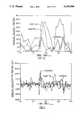
- FIGS. 9, 10, and 11are diagrams illustrating a typical output of the angular position, velocity, and acceleration as a function of time, respectively.
- FIG. 1illustrates an apparatus 10 which embodies the present invention and which is shown mounted on the back of a patient.
- the apparatusis used to monitor the movement of the spine, and particularly the lumbar spine.
- the apparatus 10includes an elongate exoskeleton 12 comprising a plurality of generally flat, T-shaped elements 14 which are disposed in a longitudinally spaced apart arrangement.
- each element 14is composed of a horizontal base leg 15, and an upright leg 16.
- each elementincludes a central bore 17 at the intersection of the two legs, with the bore 17 extending longitudinally therethrough.
- first and second smaller openings 18, 19are positioned at the respective ends of the horizontal base leg on opposite sides of the central bore 17, and such that the bore 17 and the first and second openings 18, 19 lie substantially in a common horizontal plane.
- a third opening 20is provided adjacent the free end of the upright leg 16, and such that the third opening 20 is equally spaced from the first and second openings, and the first, second, and third openings are disposed in a triangular arrangement.
- the elements 14are each disposed in parallel transverse planes, and they are aligned along the longitudinal direction.
- the central bores 17 of the elementsare also longitudinally aligned to define a central longitudinal axis.
- the first, second, and third openings of each elementare longitudinally aligned with the corresponding openings of the other elements.
- a tubular spacer 22is disposed between each adjacent pair of elements 14 for maintaining the separation thereof, and with the spacers 22 being longitudinally aligned with the central bores and thus with the central axis.
- the spacers 22are not fixedly attached to the elements, but are supported in the described position by the structure set forth below, and so as to permit relative motion of the elements 14 in all axes.
- the apparatus 10also includes support means for supporting the exoskeleton 12 on the back of a patient and so that the exoskeleton is generally aligned along the spine as best seen in FIG. 1.
- This support meansincludes an upper assembly 24, and a lower assembly 26. More particularly, the upper assembly 24 includes a support plate 28, which is fixedly attached to a harness 29 which is in the form of a figure eight and which loops about the shoulders of the patient.
- the harness 29is preferably fabricated from a semi-rigid material, such as "Orthoplast" material sold by Johnson & Johnson, and which is open in the front, and with the front being closed by suitable straps having VELCRO interconnection means (not shown). This construction provides a stable mounting of the exoskeleton 12 to the upper body of the wearer.
- the upper assembly 24also includes a top plate 30 which is slideably connected to the support plate 28.
- the top plate 30has an L-shaped configuration so as to include a flat lower segment 31 and an upright segment 32.
- the support plate 28includes opposing side members 33 which define opposing slots, and the lower segment 31 of the top plate fits within the slots as best seen in FIG. 5, and so that the top plate is free to slide in the longitudinal direction with respect to the support plate.
- a pair of springs 35extend between the side members 33 and the upright segment 32 of the top plate, and act to bias the top plate upwardly with respect to the support plate and the strap.
- the lower segment 31 of the top platemounts a bracket 36 having an upright leg 37 which contains a horizontal slot, for the purposes described below.
- the lower assembly 26includes a base plate 40 which is mounted to a belt 41, and such that the belt releasably secures the base plate on the lower back of the patient.
- the belt 41comprises a waist band which may also be composed of "Orthoplast" material, and, which may be divided in front and include VELCRO interconnection means (not shown).
- a pair of straps 42are attached to the waist band and extend between the legs of the patient.
- the apparatus 10 of the present inventionalso includes wire means 44 extending longitudinally through each of the three aligned openings 18, 19, 20 of the elements 14, and with each of the wire means 44 being resiliently extensible in length. More particularly, each of the wire means includes a non-extensible solid wire 45, and an extensible spring 46 attached to one end of the wire. Each wire 45 has its opposite end fixed to the upright segment 32 of the top plate 30, and each wire 45 runs through all of the elements and to a point adjacent the lower portion of the base plate 40 where it joins one end of the spring 46. The opposite end of the spring 46 is connected to a threaded member 47, which in turn is joined to the upright flange 48 of the base plate 40.
- Movement signaling meansis mounted on the base plate for detecting longitudinal movement of each of the wire means caused by changes in length thereof, and for providing an output signal representative of such movement.
- this signaling meanscomprises three electrical potentiometers 50, 51, 52 mounted to the base plate.
- Each potentiometerincludes a pulley 50a, 51a, 52a respectively, and the associated wire 45 is wrapped about the pulley so that any longitudinal movement of the wire with respect to the base plate causes the associated pulley and potentiometer to rotate.
- the apparatus 10further includes a cable 54 extending longitudinally through the aligned bores 17 of the segments and coaxially through the spacers 22.
- the cable 54which preferably comprises a piano wire, has one end attached to a plate 55 which is slideably received in the slot of the bracket 36 as best seen in FIG. 5, and a spring 56 is interposed between the end of the cable and the upright segment 32 of the top plate.
- the slideable interconnection formed between the plate 55 and the bracket 36accommodates the elongation of the spine which occurs when the patient bends forward, while maintaining cable 54 in a fixed rotational orientation at its upper end.
- the apparatus of the present inventionmay further include a multiplexing circuit 61 and a telemetry circuit 62 mounted on the base plate 40 of the apparatus.
- the multiplexing circuit 61provides power to the four potentiometers, and sequentially mixes the signals from each of the potentiometers.
- the telemetry circuit 62then transmits the mixed signals to a data acquisition computer 64 which demultiplexes the signal received from the telemetry circuit.
- the data acquisition computer 64may be programmed to smooth the data and convert the signals to angular position via a calibration, and then store the resulting data.
- the softwaresorts the data for each of three planes of movement, namely the sagittal, transverse, and lateral planes.
- the motion characteristics in each planeinclude the angular position of the spine relative to the position to the pelvis considered as a function of time, and as illustrated in FIG. 9. This information may then be differentiated to determine the angular velocity of the spine as a function of time and as illustrated in FIG. 10, as well as the angular acceleration of the spine as a function of time and as illustrated in FIG. 11.
- the potentiometersmay be hardwired directly to the computer 64 as schematically illustrated by the dashed line 65 in FIG. 8, thus bypassing the multiplexing circuit 61 and the telemetry circuit 62.
- a calibration tableis used to calibrate the apparatus of the present invention. Specifically, the apparatus is placed in the calibration table and the position of the apparatus is moved to a large number of different positions in space. The four potentiometer voltages associated with each of these positions is then recorded in the computer, and these voltages are then used to uniquely described the positions of the apparatus in space. A mathematical regression model is then used to estimate a best fit plane between the potentiometer voltages and the position in space of the apparatus. Therefore, when the apparatus is in use the voltage readings from the four potentiometers are compared to the model and the exact position of the apparatus in space is determined. As noted above, this information is then differentiated to determine instantaneous angular velocity and acceleration.
Landscapes
- Health & Medical Sciences (AREA)
- Life Sciences & Earth Sciences (AREA)
- Engineering & Computer Science (AREA)
- General Health & Medical Sciences (AREA)
- Biomedical Technology (AREA)
- Physics & Mathematics (AREA)
- Molecular Biology (AREA)
- Veterinary Medicine (AREA)
- Biophysics (AREA)
- Oral & Maxillofacial Surgery (AREA)
- Heart & Thoracic Surgery (AREA)
- Medical Informatics (AREA)
- Dentistry (AREA)
- Surgery (AREA)
- Animal Behavior & Ethology (AREA)
- Pathology (AREA)
- Public Health (AREA)
- Physiology (AREA)
- Pulmonology (AREA)
- Neurology (AREA)
- Orthopedic Medicine & Surgery (AREA)
- Physical Education & Sports Medicine (AREA)
- Geometry (AREA)
- Measurement Of The Respiration, Hearing Ability, Form, And Blood Characteristics Of Living Organisms (AREA)
- Orthopedics, Nursing, And Contraception (AREA)
Abstract
Description
Claims (6)
Priority Applications (1)
| Application Number | Priority Date | Filing Date | Title |
|---|---|---|---|
| US07/696,370US5143088A (en) | 1989-04-12 | 1991-05-06 | Apparatus for monitoring the motion components of the spine |
Applications Claiming Priority (2)
| Application Number | Priority Date | Filing Date | Title |
|---|---|---|---|
| US33689689A | 1989-04-12 | 1989-04-12 | |
| US07/696,370US5143088A (en) | 1989-04-12 | 1991-05-06 | Apparatus for monitoring the motion components of the spine |
Related Parent Applications (1)
| Application Number | Title | Priority Date | Filing Date |
|---|---|---|---|
| US07/551,649ContinuationUS5012819A (en) | 1989-04-12 | 1990-07-11 | Apparatus for monitoring the motion components of the spine |
Publications (1)
| Publication Number | Publication Date |
|---|---|
| US5143088Atrue US5143088A (en) | 1992-09-01 |
Family
ID=26990443
Family Applications (1)
| Application Number | Title | Priority Date | Filing Date |
|---|---|---|---|
| US07/696,370Expired - LifetimeUS5143088A (en) | 1989-04-12 | 1991-05-06 | Apparatus for monitoring the motion components of the spine |
Country Status (1)
| Country | Link |
|---|---|
| US (1) | US5143088A (en) |
Cited By (43)
| Publication number | Priority date | Publication date | Assignee | Title |
|---|---|---|---|---|
| USD342817S (en) | 1992-05-14 | 1993-12-28 | Sterilite Corporation | Lidded wastebasket |
| US5398697A (en)* | 1994-05-10 | 1995-03-21 | Spielman; Steven B. | Apparatus for monitoring spinal motion |
| WO1996004848A1 (en)* | 1994-08-15 | 1996-02-22 | Harri Arikka | Method and device for the simultaneous analysis of ambulatorily recorded movements of an individual's different body parts |
| US5621667A (en)* | 1993-11-30 | 1997-04-15 | The United States Of America As Represented By The Department Of Health And Human Services | Lift task analysis system |
| US5772610A (en)* | 1996-08-14 | 1998-06-30 | Liberty Mutual Group | Method and apparatus for dynamic and direct measurement of lumbar lordosis |
| US5891060A (en)* | 1997-10-13 | 1999-04-06 | Kinex Iha Corp. | Method for evaluating a human joint |
| US5954674A (en)* | 1997-10-13 | 1999-09-21 | Kinex Iha Corporation | Apparatus for gathering biomechanical parameters |
| US5991701A (en)* | 1997-10-13 | 1999-11-23 | Kinex Iha Corp. | Method for improved instantaneous helical axis determination |
| US5989201A (en)* | 1996-11-28 | 1999-11-23 | Zebris Medizintechnik Gmbh | Device for measuring the mobility of the back or trunk of a patient |
| US6050963A (en)* | 1998-06-18 | 2000-04-18 | Innovative Sports Training, Inc. | System for analyzing the motion of lifting an object |
| KR100349338B1 (en)* | 1999-03-29 | 2002-08-21 | 홍정화 | Clinical diagnosis system for orthopedic pathological disease using three-dimensional human motion measurement |
| US6519862B1 (en)* | 2000-10-04 | 2003-02-18 | The United States Of America As Represented By The Secretary Of The Navy | Device for the acquisition of contoured human body surface vibration signals |
| US6656135B2 (en) | 2000-05-01 | 2003-12-02 | Southwest Research Institute | Passive and wireless displacement measuring device |
| EP1369146A1 (en)* | 2002-06-07 | 2003-12-10 | Christophe Van Dongen | Posture detector |
| US6673027B2 (en) | 2000-04-13 | 2004-01-06 | Peter Fischer | Posture measurement and feedback instrument for seated occupations |
| US20050203443A1 (en)* | 2003-03-15 | 2005-09-15 | Salvi Frank J. | Apparatus and method for measuring and monitoring range of motion of the lumbar spine |
| FR2878961A1 (en)* | 2004-12-06 | 2006-06-09 | Daniel Henri Lucien Jos Martin | DEVICE INDICATING MOVEMENTS OF A BODY |
| WO2007110289A1 (en)* | 2006-03-27 | 2007-10-04 | Siemens Aktiengesellschaft | Method, device and use of a fibre-optic flexion sensor for determining a shape of at least one part of a spinal column |
| WO2009038493A1 (en)* | 2007-09-21 | 2009-03-26 | Logvinenko, Mikhail Eniseevich | Back bone position checking device |
| US20110063114A1 (en)* | 2009-09-15 | 2011-03-17 | Dikran Ikoyan | Posture training device |
| US20110067253A1 (en)* | 2009-09-21 | 2011-03-24 | Tobias Happel | Method and System for Detecting Parameters for the Characterization of Motion Sequences at the Human Body and Computer-Implemented Method for Analyzing Parameters for the Characterization of Motion Sequences at the Human Body |
| WO2011047647A1 (en) | 2009-10-22 | 2011-04-28 | Otto Bock Healthcare Gmbh | Device for detecting and/or influencing posture |
| EP2343011A1 (en) | 2009-08-18 | 2011-07-13 | Peter Fischer | Posture assessment and feedback device |
| US8083693B1 (en) | 2007-03-30 | 2011-12-27 | Perseus Athletics, LLC | Monitoring posture |
| US20120198715A1 (en)* | 2009-10-15 | 2012-08-09 | Koninklijke Philips Electronics N.V. | Apparatus and method for measuring a body part |
| US8241231B2 (en) | 2006-03-27 | 2012-08-14 | Siemens Aktiengesellschaft | Device, sensor, sensor element and method for measuring the profile of a spinal column and for measuring changes in the profile of the spinal column |
| RU2463997C2 (en)* | 2009-12-28 | 2012-10-20 | Рамиль Равильевич Мусакаев | Device of external fixation of thoracolumbar spine |
| WO2013060388A1 (en) | 2011-10-28 | 2013-05-02 | Bruyland Dirk | Lower back pain training device |
| US20130201021A1 (en)* | 2012-02-08 | 2013-08-08 | Farhad M. Limonadi | Method and apparatus for limiting range of motion of body |
| US8928484B2 (en) | 2011-07-13 | 2015-01-06 | Lumo Bodytech, Inc. | System and method of biomechanical posture detection and feedback |
| US9033903B2 (en) | 2012-07-12 | 2015-05-19 | The Trustees Of The Stevens Institute Of Technology | Tri-axial electro-goniometer for spinal motion, associated system and methods |
| US20150217162A1 (en)* | 2012-08-17 | 2015-08-06 | Gravity Fitness Australia Pty Ltd | Thoracic stabilizer |
| US9541994B2 (en) | 2011-07-13 | 2017-01-10 | Lumo BodyTech, Inc | System and method of biomechanical posture detection and feedback including sensor normalization |
| US9591996B2 (en) | 2013-06-07 | 2017-03-14 | Lumo BodyTech, Inc | System and method for detecting transitions between sitting and standing states |
| US9763581B2 (en) | 2003-04-23 | 2017-09-19 | P Tech, Llc | Patient monitoring apparatus and method for orthosis and other devices |
| US20170296129A1 (en)* | 2016-04-13 | 2017-10-19 | Strong Arm Technologies, Inc. | Systems and devices for motion tracking, assessment, and monitoring and methods of use thereof |
| WO2017181744A1 (en)* | 2016-04-21 | 2017-10-26 | 深圳市前海康启源科技有限公司 | Back apparatus used for maintaining healthy body posture |
| JP2019505398A (en)* | 2015-12-24 | 2019-02-28 | サフラン・エレクトロニクス・アンド・デファンス | Back module for exoskeleton structure |
| US10314520B2 (en) | 2015-10-02 | 2019-06-11 | Seismic Holdings, Inc. | System and method for characterizing biomechanical activity |
| US10463909B2 (en) | 2015-12-27 | 2019-11-05 | Seismic Holdings, Inc. | System and method for using performance signatures |
| US10959647B2 (en) | 2015-12-30 | 2021-03-30 | Seismic Holdings, Inc. | System and method for sensing and responding to fatigue during a physical activity |
| US11452652B1 (en) | 2016-11-28 | 2022-09-27 | Cerner Innovation, Inc. | Predicting and preventing caregiver musculoskeletal injuries |
| WO2023209254A1 (en)* | 2022-04-26 | 2023-11-02 | Pablo Esteban Gonzalez Pablo | Device for measuring spinal movements and measuring method |
Citations (12)
| Publication number | Priority date | Publication date | Assignee | Title |
|---|---|---|---|---|
| US3608541A (en)* | 1969-12-18 | 1971-09-28 | Oasis Electronics | Poor posture detectors |
| US3908279A (en)* | 1973-08-29 | 1975-09-30 | Wilmark Electronic Co | Curvature measurement device |
| US3991745A (en)* | 1973-08-29 | 1976-11-16 | Wilmark Electronic Co., Inc. | Curvature measurement device |
| US4108164A (en)* | 1976-10-01 | 1978-08-22 | Hall Sr Henry W | Standard bending profile jacket |
| US4461085A (en)* | 1981-03-27 | 1984-07-24 | National Research Development Corporation | Goniometer |
| US4528990A (en)* | 1983-06-27 | 1985-07-16 | Knowles Wayne C | Apparatus for measuring head and spine movement |
| WO1987000026A1 (en)* | 1985-06-24 | 1987-01-15 | Se-Produkter | A device for detection of relative movements and/or positions of a part of the body or the like |
| US4655227A (en)* | 1985-06-06 | 1987-04-07 | Diagnospine Research Inc. | Equipment for the detection of mechanical injuries in the lumbar spine of a patient, using a mathematical model |
| US4699156A (en)* | 1985-06-06 | 1987-10-13 | Diagnospine Research Inc. | Non invasive method and equipment for the detection of torsional injuries in the lumar spine of a patient |
| SE455567B (en)* | 1986-11-28 | 1988-07-25 | Bertil Josefsson | DEVICE FOR DETAILS OF DETAILS ON A LED, SPEC BACKGROUND |
| US4768779A (en)* | 1987-12-01 | 1988-09-06 | Isotechnologies, Inc. | Back exercise apparatus with a neck exercise attachment |
| US4971069A (en)* | 1987-10-05 | 1990-11-20 | Diagnospine Research Inc. | Method and equipment for evaluating the flexibility of a human spine |
- 1991
- 1991-05-06USUS07/696,370patent/US5143088A/ennot_activeExpired - Lifetime
Patent Citations (14)
| Publication number | Priority date | Publication date | Assignee | Title |
|---|---|---|---|---|
| US3608541A (en)* | 1969-12-18 | 1971-09-28 | Oasis Electronics | Poor posture detectors |
| US3908279A (en)* | 1973-08-29 | 1975-09-30 | Wilmark Electronic Co | Curvature measurement device |
| US3991745A (en)* | 1973-08-29 | 1976-11-16 | Wilmark Electronic Co., Inc. | Curvature measurement device |
| US4108164A (en)* | 1976-10-01 | 1978-08-22 | Hall Sr Henry W | Standard bending profile jacket |
| US4461085A (en)* | 1981-03-27 | 1984-07-24 | National Research Development Corporation | Goniometer |
| US4528990A (en)* | 1983-06-27 | 1985-07-16 | Knowles Wayne C | Apparatus for measuring head and spine movement |
| US4699156A (en)* | 1985-06-06 | 1987-10-13 | Diagnospine Research Inc. | Non invasive method and equipment for the detection of torsional injuries in the lumar spine of a patient |
| US4655227A (en)* | 1985-06-06 | 1987-04-07 | Diagnospine Research Inc. | Equipment for the detection of mechanical injuries in the lumbar spine of a patient, using a mathematical model |
| WO1987000026A1 (en)* | 1985-06-24 | 1987-01-15 | Se-Produkter | A device for detection of relative movements and/or positions of a part of the body or the like |
| US4800897A (en)* | 1985-06-24 | 1989-01-31 | Se-Produkter | Device for detection of relative movements and/or positions of a part of the body or the like |
| SE455567B (en)* | 1986-11-28 | 1988-07-25 | Bertil Josefsson | DEVICE FOR DETAILS OF DETAILS ON A LED, SPEC BACKGROUND |
| WO1989011247A1 (en)* | 1986-11-28 | 1989-11-30 | Bertil Josefsson | Means for detection of spinal movements |
| US4971069A (en)* | 1987-10-05 | 1990-11-20 | Diagnospine Research Inc. | Method and equipment for evaluating the flexibility of a human spine |
| US4768779A (en)* | 1987-12-01 | 1988-09-06 | Isotechnologies, Inc. | Back exercise apparatus with a neck exercise attachment |
Non-Patent Citations (6)
| Title |
|---|
| "Flexibility and Velocity of the Normal and Impaired Lumbar Spine"; Archives of Physical Medicine and Rehabilitation, vol. 67, Apr., 1986, pp. 213-217. |
| "The Low Back Machine That Moves Like The Low Back", Isotechnologies Inc., one page. |
| Flexibility and Velocity of the Normal and Impaired Lumbar Spine ; Archives of Physical Medicine and Rehabilitation, vol. 67, Apr., 1986, pp. 213 217.* |
| Operating Manual for Ady Hall Lumbar Monitor entitled Lumbar Hygiene , comprising cover sheet and 16 pages, dated May 13, 1983.* |
| Operating Manual for Ady-Hall Lumbar Monitor entitled "Lumbar Hygiene", comprising cover sheet and 16 pages, dated May 13, 1983. |
| The Low Back Machine That Moves Like The Low Back , Isotechnologies Inc., one page.* |
Cited By (66)
| Publication number | Priority date | Publication date | Assignee | Title |
|---|---|---|---|---|
| USD342817S (en) | 1992-05-14 | 1993-12-28 | Sterilite Corporation | Lidded wastebasket |
| US5621667A (en)* | 1993-11-30 | 1997-04-15 | The United States Of America As Represented By The Department Of Health And Human Services | Lift task analysis system |
| US5398697A (en)* | 1994-05-10 | 1995-03-21 | Spielman; Steven B. | Apparatus for monitoring spinal motion |
| WO1996004848A1 (en)* | 1994-08-15 | 1996-02-22 | Harri Arikka | Method and device for the simultaneous analysis of ambulatorily recorded movements of an individual's different body parts |
| US5851193A (en)* | 1994-08-15 | 1998-12-22 | Arikka; Harri | Method and device for the simultaneous analysis of ambulatorily recorded movements of an individual's different body parts |
| US5772610A (en)* | 1996-08-14 | 1998-06-30 | Liberty Mutual Group | Method and apparatus for dynamic and direct measurement of lumbar lordosis |
| US5989201A (en)* | 1996-11-28 | 1999-11-23 | Zebris Medizintechnik Gmbh | Device for measuring the mobility of the back or trunk of a patient |
| US5991701A (en)* | 1997-10-13 | 1999-11-23 | Kinex Iha Corp. | Method for improved instantaneous helical axis determination |
| US5954674A (en)* | 1997-10-13 | 1999-09-21 | Kinex Iha Corporation | Apparatus for gathering biomechanical parameters |
| US5891060A (en)* | 1997-10-13 | 1999-04-06 | Kinex Iha Corp. | Method for evaluating a human joint |
| US6050963A (en)* | 1998-06-18 | 2000-04-18 | Innovative Sports Training, Inc. | System for analyzing the motion of lifting an object |
| KR100349338B1 (en)* | 1999-03-29 | 2002-08-21 | 홍정화 | Clinical diagnosis system for orthopedic pathological disease using three-dimensional human motion measurement |
| US6673027B2 (en) | 2000-04-13 | 2004-01-06 | Peter Fischer | Posture measurement and feedback instrument for seated occupations |
| US6656135B2 (en) | 2000-05-01 | 2003-12-02 | Southwest Research Institute | Passive and wireless displacement measuring device |
| US20040068205A1 (en)* | 2000-05-01 | 2004-04-08 | Southwest Research Institute | Passive and wireless displacement measuring device using parallel sensors |
| US6519862B1 (en)* | 2000-10-04 | 2003-02-18 | The United States Of America As Represented By The Secretary Of The Navy | Device for the acquisition of contoured human body surface vibration signals |
| EP1369146A1 (en)* | 2002-06-07 | 2003-12-10 | Christophe Van Dongen | Posture detector |
| US20050237209A1 (en)* | 2002-06-07 | 2005-10-27 | Christophe Van Dongen | Posture detector |
| WO2003103780A1 (en)* | 2002-06-07 | 2003-12-18 | Christophe Van Dongen | Posture detector |
| US7431703B2 (en)* | 2003-03-15 | 2008-10-07 | Salvi Frank J | Apparatus and method for measuring and monitoring range of motion of the lumbar spine |
| US20050203443A1 (en)* | 2003-03-15 | 2005-09-15 | Salvi Frank J. | Apparatus and method for measuring and monitoring range of motion of the lumbar spine |
| US9763581B2 (en) | 2003-04-23 | 2017-09-19 | P Tech, Llc | Patient monitoring apparatus and method for orthosis and other devices |
| FR2878961A1 (en)* | 2004-12-06 | 2006-06-09 | Daniel Henri Lucien Jos Martin | DEVICE INDICATING MOVEMENTS OF A BODY |
| WO2006061501A1 (en) | 2004-12-06 | 2006-06-15 | Daniel Martin | Device for indicating movements in a body |
| WO2007110289A1 (en)* | 2006-03-27 | 2007-10-04 | Siemens Aktiengesellschaft | Method, device and use of a fibre-optic flexion sensor for determining a shape of at least one part of a spinal column |
| US8241231B2 (en) | 2006-03-27 | 2012-08-14 | Siemens Aktiengesellschaft | Device, sensor, sensor element and method for measuring the profile of a spinal column and for measuring changes in the profile of the spinal column |
| US8932236B1 (en) | 2007-03-30 | 2015-01-13 | Perseus Athletics, LLC | Monitoring posture |
| US8083693B1 (en) | 2007-03-30 | 2011-12-27 | Perseus Athletics, LLC | Monitoring posture |
| WO2009038493A1 (en)* | 2007-09-21 | 2009-03-26 | Logvinenko, Mikhail Eniseevich | Back bone position checking device |
| US8157752B2 (en) | 2009-08-18 | 2012-04-17 | Peter Fischer | Posture assessment and feedback instrument |
| EP2343011A1 (en) | 2009-08-18 | 2011-07-13 | Peter Fischer | Posture assessment and feedback device |
| US8217797B2 (en)* | 2009-09-15 | 2012-07-10 | Dikran Ikoyan | Posture training device |
| US20110063114A1 (en)* | 2009-09-15 | 2011-03-17 | Dikran Ikoyan | Posture training device |
| US20110067253A1 (en)* | 2009-09-21 | 2011-03-24 | Tobias Happel | Method and System for Detecting Parameters for the Characterization of Motion Sequences at the Human Body and Computer-Implemented Method for Analyzing Parameters for the Characterization of Motion Sequences at the Human Body |
| US20120198715A1 (en)* | 2009-10-15 | 2012-08-09 | Koninklijke Philips Electronics N.V. | Apparatus and method for measuring a body part |
| DE102009050385A1 (en) | 2009-10-22 | 2011-05-05 | Otto Bock Healthcare Gmbh | Device for detecting and / or influencing posture |
| WO2011047647A1 (en) | 2009-10-22 | 2011-04-28 | Otto Bock Healthcare Gmbh | Device for detecting and/or influencing posture |
| RU2463997C2 (en)* | 2009-12-28 | 2012-10-20 | Рамиль Равильевич Мусакаев | Device of external fixation of thoracolumbar spine |
| US8928484B2 (en) | 2011-07-13 | 2015-01-06 | Lumo Bodytech, Inc. | System and method of biomechanical posture detection and feedback |
| US10276020B2 (en) | 2011-07-13 | 2019-04-30 | Seismic Holdings, Inc. | System and method of biomechanical posture detection and feedback |
| US9940811B2 (en) | 2011-07-13 | 2018-04-10 | Lumo BodyTech, Inc | System and method of biomechanical posture detection and feedback |
| US9936900B2 (en) | 2011-07-13 | 2018-04-10 | Lumo BodyTech, Inc | System and method of biomechanical posture detection and feedback including sensor normalization |
| US9514625B2 (en) | 2011-07-13 | 2016-12-06 | Lumo BodyTech, Inc | System and method of biomechanical posture detection and feedback |
| US9541994B2 (en) | 2011-07-13 | 2017-01-10 | Lumo BodyTech, Inc | System and method of biomechanical posture detection and feedback including sensor normalization |
| US10271773B2 (en) | 2011-07-13 | 2019-04-30 | Seismic Holdings, Inc. | System and method of biomechanical posture detection and feedback including sensor normalization |
| WO2013060388A1 (en) | 2011-10-28 | 2013-05-02 | Bruyland Dirk | Lower back pain training device |
| US20130201021A1 (en)* | 2012-02-08 | 2013-08-08 | Farhad M. Limonadi | Method and apparatus for limiting range of motion of body |
| US9799187B2 (en)* | 2012-02-08 | 2017-10-24 | Farhad M. Limonadi | Method and apparatus for limiting range of motion of body |
| US9033903B2 (en) | 2012-07-12 | 2015-05-19 | The Trustees Of The Stevens Institute Of Technology | Tri-axial electro-goniometer for spinal motion, associated system and methods |
| US20150217162A1 (en)* | 2012-08-17 | 2015-08-06 | Gravity Fitness Australia Pty Ltd | Thoracic stabilizer |
| US10010749B2 (en)* | 2012-08-17 | 2018-07-03 | Carolyn Anne Richardson | Thoracic stabilizer |
| US9591996B2 (en) | 2013-06-07 | 2017-03-14 | Lumo BodyTech, Inc | System and method for detecting transitions between sitting and standing states |
| US10314520B2 (en) | 2015-10-02 | 2019-06-11 | Seismic Holdings, Inc. | System and method for characterizing biomechanical activity |
| JP2019505398A (en)* | 2015-12-24 | 2019-02-28 | サフラン・エレクトロニクス・アンド・デファンス | Back module for exoskeleton structure |
| US10463909B2 (en) | 2015-12-27 | 2019-11-05 | Seismic Holdings, Inc. | System and method for using performance signatures |
| US10959647B2 (en) | 2015-12-30 | 2021-03-30 | Seismic Holdings, Inc. | System and method for sensing and responding to fatigue during a physical activity |
| US20210290176A1 (en)* | 2016-04-13 | 2021-09-23 | Strongarm Technologies, Inc. | Systems and methods for improving workplace safety |
| US20170296129A1 (en)* | 2016-04-13 | 2017-10-19 | Strong Arm Technologies, Inc. | Systems and devices for motion tracking, assessment, and monitoring and methods of use thereof |
| US10123751B2 (en)* | 2016-04-13 | 2018-11-13 | Strongarm Technologies, Inc. | Systems and devices for motion tracking, assessment, and monitoring and methods of use thereof |
| US20230225680A1 (en)* | 2016-04-13 | 2023-07-20 | Strongarm Technologies, Inc. | Systems and methods for monitoring workplace activities |
| US20240164728A1 (en)* | 2016-04-13 | 2024-05-23 | Rs1Worklete Llc | Systems and methods for improving workplace safety |
| WO2017181744A1 (en)* | 2016-04-21 | 2017-10-26 | 深圳市前海康启源科技有限公司 | Back apparatus used for maintaining healthy body posture |
| US11452652B1 (en) | 2016-11-28 | 2022-09-27 | Cerner Innovation, Inc. | Predicting and preventing caregiver musculoskeletal injuries |
| US11752053B2 (en) | 2016-11-28 | 2023-09-12 | Cerner Innovation, Inc. | Predicting and preventing caregiver musculoskeletal injuries |
| WO2023209254A1 (en)* | 2022-04-26 | 2023-11-02 | Pablo Esteban Gonzalez Pablo | Device for measuring spinal movements and measuring method |
| ES2955606A1 (en)* | 2022-04-26 | 2023-12-04 | Gonzalez Pablo Esteban | DEVICE FOR MEASURING MOVEMENTS OF THE VERTEBRAL COLUMN AND MEASUREMENT PROCEDURE (Machine-translation by Google Translate, not legally binding) |
Similar Documents
| Publication | Publication Date | Title |
|---|---|---|
| US5143088A (en) | Apparatus for monitoring the motion components of the spine | |
| US5012819A (en) | Apparatus for monitoring the motion components of the spine | |
| US5146929A (en) | Lumbar spine motion sensor | |
| US4768779A (en) | Back exercise apparatus with a neck exercise attachment | |
| US5188121A (en) | Range of motion instruments for the spine | |
| US4986280A (en) | Hand position/measurement control system | |
| US7698830B2 (en) | Posture and body movement measuring system | |
| US4108164A (en) | Standard bending profile jacket | |
| US4938476A (en) | Body position attitude indicator device | |
| JP3190404B2 (en) | Spinal motion analyzer | |
| US5772610A (en) | Method and apparatus for dynamic and direct measurement of lumbar lordosis | |
| US4800897A (en) | Device for detection of relative movements and/or positions of a part of the body or the like | |
| US5758658A (en) | Compact human range of motion measurement system | |
| US20030115954A1 (en) | Upper extremity exoskeleton structure and method | |
| US6651352B2 (en) | Wrist motion measurement device | |
| US4548289A (en) | Variable resistance tiltboard for evaluation of balance reactions | |
| EP0710466A1 (en) | An orthopaedic measurement and display system | |
| EP0467956B1 (en) | Apparatus for monitoring the motion components of the spine | |
| US7431703B2 (en) | Apparatus and method for measuring and monitoring range of motion of the lumbar spine | |
| US9033903B2 (en) | Tri-axial electro-goniometer for spinal motion, associated system and methods | |
| JP2006055532A (en) | Motion analysis device | |
| CN222110873U (en) | Three-point induction sit-up tester | |
| CN216724552U (en) | Portable cervical vertebra mobility evaluation device | |
| Sexton et al. | The development of a wearable motion analysis system | |
| WO1985000742A1 (en) | Range of motion apparatus |
Legal Events
| Date | Code | Title | Description |
|---|---|---|---|
| STCF | Information on status: patent grant | Free format text:PATENTED CASE | |
| FEPP | Fee payment procedure | Free format text:PAYOR NUMBER ASSIGNED (ORIGINAL EVENT CODE: ASPN); ENTITY STATUS OF PATENT OWNER: SMALL ENTITY | |
| FPAY | Fee payment | Year of fee payment:4 | |
| AS | Assignment | Owner name:WACHOVIA BANK, N.A., GEORGIA Free format text:SECURITY INTEREST;ASSIGNOR:CHATTANOOGA GROUP, INC.;REEL/FRAME:009996/0751 Effective date:19990730 | |
| FEPP | Fee payment procedure | Free format text:PAYER NUMBER DE-ASSIGNED (ORIGINAL EVENT CODE: RMPN); ENTITY STATUS OF PATENT OWNER: SMALL ENTITY Free format text:PAYOR NUMBER ASSIGNED (ORIGINAL EVENT CODE: ASPN); ENTITY STATUS OF PATENT OWNER: SMALL ENTITY | |
| FPAY | Fee payment | Year of fee payment:8 | |
| AS | Assignment | Owner name:MARRAS, WILLIAM S., OHIO Free format text:RELEASE OF SECURITY INTEREST;ASSIGNOR:WACHOVIA BANK, N.A.;REEL/FRAME:012463/0336 Effective date:20011015 | |
| FPAY | Fee payment | Year of fee payment:12 | |
| AS | Assignment | Owner name:ENCORE MEDICAL, L.P. AS SUCCESSOR IN INTEREST TO T Free format text:RELEASE BY SECURED PARTY;ASSIGNOR:WACHOVIA BANK, N.A.;REEL/FRAME:018224/0954 Effective date:20020208 |