US5142806A - Universal receiver sleeve - Google Patents
Universal receiver sleeveDownload PDFInfo
- Publication number
- US5142806A US5142806AUS07/763,966US76396691AUS5142806AUS 5142806 AUS5142806 AUS 5142806AUS 76396691 AUS76396691 AUS 76396691AUS 5142806 AUS5142806 AUS 5142806A
- Authority
- US
- United States
- Prior art keywords
- section
- longitudinal
- recited
- firearm
- interface means
- Prior art date
- Legal status (The legal status is an assumption and is not a legal conclusion. Google has not performed a legal analysis and makes no representation as to the accuracy of the status listed.)
- Expired - Lifetime
Links
- 230000010354integrationEffects0.000description2
- 230000003287optical effectEffects0.000description2
- 239000011324beadSubstances0.000description1
- 238000009434installationMethods0.000description1
- 230000003313weakening effectEffects0.000description1
Images


Classifications
- F—MECHANICAL ENGINEERING; LIGHTING; HEATING; WEAPONS; BLASTING
- F41—WEAPONS
- F41G—WEAPON SIGHTS; AIMING
- F41G11/00—Details of sighting or aiming apparatus; Accessories
- F41G11/001—Means for mounting tubular or beam shaped sighting or aiming devices on firearms
- F41G11/003—Mountings with a dove tail element, e.g. "Picatinny rail systems"
- F—MECHANICAL ENGINEERING; LIGHTING; HEATING; WEAPONS; BLASTING
- F41—WEAPONS
- F41C—SMALLARMS, e.g. PISTOLS, RIFLES; ACCESSORIES THEREFOR
- F41C33/00—Means for wearing or carrying smallarms
- F41C33/08—Handles for carrying smallarms
- F—MECHANICAL ENGINEERING; LIGHTING; HEATING; WEAPONS; BLASTING
- F41—WEAPONS
- F41G—WEAPON SIGHTS; AIMING
- F41G1/00—Sighting devices
- F41G1/32—Night sights, e.g. luminescent
- F41G1/34—Night sights, e.g. luminescent combined with light source, e.g. spot light
Definitions
- This inventionrelates to integration means, and more particularly to a device added to the upper receiver of a firearm for incorporating firearm ancillary equipment.
- the female portion of said railis a quick detachable interface means for modular enhancements.
- the said railrequires a first rail (weaver rail) to be attached to the firearm, typically to the arced handle on the U.S. Army M16 combat firearm, and different means on other types.
- the first railmust be designed for each firearm to accommodate the differences between firearm receivers. Since the male portion of the Swan/Weaver rail is easily removed by the firearm operator, they are also easily lost and calibration and weapon sighting are difficult and nonuniform.
- the present inventionprovides a modular firearm receiver via a sleeve.
- the general purpose of the present inventionis to provide a new and improved interface means for firearms which will present a standard interface to modular enhancements regardless of which type or manufacturer's firearm the sleeve is integrated to thus allowing a weapon's manufacturer to tailor a weapon to the specific capabilities of a customer without having to account for different receivers.
- the manufacturer of the riflewill be able to change receiver dimensions as easily as he now supplies different barrel lengths, which also attach to the receiver.
- the present inventionhas an upper enhancement interface portion and a lower firearm interface portion.
- the upper enhancement interface portionhas standard, universal dimensions regardless of the firearm.
- the lower firearm interface portionis specific to the particular firearm the invention is integrated to.
- the sleeving system of the present inventionlessens overall cost, as it eliminates the need for a wide range of interface adaptors.
- the most significant aspects of the inventionwill allow a weapons manufacturer to build one basic firearm receiver and then tailor the rifle to various customer needs via an integral sleeve.
- the sleevecan be replaced by the manufacturer as technical advances warrant, thereby avoiding having to replace expensive receivers while still upgrading capabilities.
- FIG. 1is a side elevational view of a standard combat firearm.
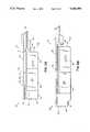
- FIG. 2Ais a side elevational view of a standard length receiver sleeve according to the present invention.
- FIG. 2Bis a side elevational view of an extended length receiver sleeve according to the present invention.
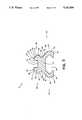
- FIG. 3is a cross sectional view along the lines 3--3 of FIGS. 2A and 2B.
- FIG. 4is a side elevational view of a standard combat firearm with the receiver sleeve of FIG. 2B mounted thereon.
- FIG. 5Ais a firearm carry handle.
- FIG. 5Bis a firearm carry handle with interface lever.
- FIG. 6Ais side elevational view of the receiver sleeve of FIG. 2A with laser, battery housing and optional dynamo.
- FIG. 6Bis side elevational view of the receiver sleeve of FIG. 2B with laser, battery housing and optional dynamo.
- FIG. 7is a side elevational view of a standard combat firearm with the receiver sleeve of FIG. 6B integrated thereto.
- FIG. 8Ais a perspective view of the receiver sleeve of FIG. 6B with active aiming capabilities.
- FIG. 8Bis a top view of the receiver sleeve of FIG. 8A.
- FIG. 8Cis a side elevational view of the receiver sleeve of FIG. 8A.
- FIG. 8Dis a front view of the receiver sleeve of FIG. 8A replacing the carrying handle of the firearm of FIG. 1.
- FIG. 1an outline of a conventional combat firearm 10 having a conventional stock 11, upper receiver 12, lower receiver 17, barrel 16, pistol grip 7, magazine 9 and arced handle 18 joined to the upper receiver 12.
- the barrel 16is also joined to the upper receiver 12, i.e., the upper receiver 12 "receives” the barrel 16.
- the arced handle 18has the after part of a non-optical bead sight with windage and elevational adjustment devices 15, 19 located at the rear thereof remote from the barrel 16.
- the handle 18 of the firearm 10 illustrated in FIG. 1is removed and a receiver sleeve 2A of standard length as illustrated in FIG. 2A or a receiver sleeve 2B of extended length as illustrated in FIG. 2B is joined to the top 13 of the upper receiver 12.
- the receiver sleeve 2has a top section 20 and a bottom section 40 and a longitudinal axis extending in spaced, parallel relation to the longitudinal axis of the firearm 10.
- the receiver sleeve top section 20has a longitudinal, horizontally positioned base portion 21 along its length.
- the base portion 21has two long side edges 29.
- a first longitudinal rail 22extends upward from the base portion 21 adjacent one of the long side edges 29 and a second longitudinal rail 23 extends upward from the base portion 21 adjacent the other of the long side edges 29.
- the second rail 23is in spaced parallel relationship to the first rail 22.
- a longitudinal opening, i.e., channel 28,is formed between the first and second rails 22, 23.
- the upper surface 24 of the first rail 22lies on the same horizontal plane as the upper surface 25 of the second rail 23.
- Optional notches 26may also be provided in the rails 22, 23.
- the notches 26provide additional means of engaging other components.
- the quantity and placement of pairs of notches 26are as required or needed.
- a series of identical and facing, rectangular notches 26are formed transversely through the first and second rails 22, 23 (second rail not shown), respectively, as shown in FIGS. 2A and 2B.
- Each of the two long side edges 29 of the base portion 21 and rails 22, 23are integral with external angled engagement surfaces 30 which extend the full length of the top section 20.
- the surfaces 30each have a middle longitudinal section 32, upper longitudinal section 31, and lower longitudinal section 33.
- the upper section 31 surface planesare directed outwardly and downwardly at a forty-five degree angle from the horizontal planes of the rail upper surfaces 24, 25.
- the middle section 32 surface planesare directed vertically downwardly from the upper section 31 surface planes in planes perpendicular to the horizontal planes of the rail upper surface 24, 25 planes.
- the lower section 33 surface planesare directed inwardly and downwardly at a forty-five degree angle from the vertical planes of the middle sections 32 to the bottom section base side edges 49.
- the longitudinal opening 28, having a rectangular U-shaped cross sectionhas a transverse width of 0.375 inch.
- the outer transverse width of the receiver sleeve top section 20is 0.835 inch.
- the transverse width of the bottom base side edges 49is 0.630 inch.
- the dimensions of the receiver sleeve top section 20remain the same regardless of the firearm the receiver sleeve 2 is attached to. This ensures that all modular enhancements need meet only one interface requirement, regardless of the firearm.
- the receiver sleeve top section 20is joined to the receiver sleeve bottom section 40.
- the receiver sleeve bottom sectionalso has a longitudinal, horizontally positioned base portion 41 along its length.
- the base portion 41has two long side edges 49.
- a first rail 42extends downward from the base portion 41 adjacent one of the long side edges 49 and a second rail 43 extends downward from the base portion 41 adjacent the other of the long side edges 49.
- the second rail 43is in spaced parallel relationship to the first rail 42.
- the top section base 21is joined in a mirrored, face to face relationship to the bottom section base 41. The joining faces of both bases 21, 41 have the same dimensions.
- the lower surface 44 of the first rail 42lies on the same horizontal plane as the lower surface 45 of the second rail 43.
- Each of the two long side edges 49 of the base portion 41 and the rails 42, 43are integral with an angled engagement surface 50 which extends the full length of the bottom section 40.
- the surface 50has an upper longitudinal section 51 and a lower longitudinal section 53.
- the upper section 51 surface planesare directed outwardly and downwardly at a forty-five degree angle from the horizontal plane of the bottom section base 41.
- the lower section 53 planesare directed vertically downward from the upper section 51 surface planes to the lower surfaces 44, 45 of the first 42 and second 43 rails, respectively.
- a longitudinal resultant opening 48is formed between the integrated rail-angled engagement surfaces 42, 50 and 43, 50.
- the cross section shape of the opening 48will vary from firearm to firearm depending on the upper receiver top 13 contour of the particular firearm.
- the opening 48is the interface and engagement means between the receiver sleeve 2 and the firearm 10.
- the nominal cross section of the opening 48 and the cross section of the receiver sleeve top section 20are identical. This permits complex integration of various modules to a firearm 10.
- the receiver sleeve 2has pins 4 affixing it to the firearm upper receiver 12 to prevent removal from the firearm 1? by other than an official armourer.
- Each pin 4passes through one of a plurality of holes 46 formed transversely through said bottom section first and second rails 42 and 43 for pinning said receiver sleeve 2 to said firearm upper receiver 12.
- FIG. 4illustrates an embodiment of the receiver sleeve 2 mounted on a firearm 10.
- the receiver sleeve 2would incorporate a standard non-optical, flip up sight 6 at the rear 35 of the receiver top section 20. Windage and elevational adjustments 15 and 19 may also be included.
- FIGS. 5A and 5Ba handle 18 is available for semi-permanent, non-removable installation on the receiver sleeve 2 of the present invention for firearm users who do not require optics.
- the handle 18 of FIG. 5Ais installed directly to the receiver sleeve top section 20 and also has pin holes 46 for pinning to the receiver sleeve top section 20 thereby preventing removal by anyone other than an official armourer.
- FIG. 5BAnother embodiment of the handle 18 has two fastener devices 14 of the '871 patent type incorporated into the handle base 15. As illustrated in the '817 patent, the handle may thereby be attached about the receiver sleeve top section 20 and used to carry the firearm 10.
- FIGS. 6A, 6B, and 7the handle 18 of the firearm 10 illustrated in FIG. 1 is removed and a receiver sleeve 2A of standard length as illustrated in FIG. 6A or a receiver sleeve 2B of extended length as illustrated in FIG. 6B, both of which have laser capabilities and an optional dynamo, is joined to the top 13 of the upper receiver 12.
- the receiver sleeves 2A and 2B of FIGS. 2A and 2Bhave a longitudinal module 60 integrated with and positioned to the side of the receiver sleeve 2, resulting in the receiver sleeves 3A and 3B respectively.
- the longitudinal axis of the module 60parallel to the longitudinal axis of the receiver sleeve 2.
- the module 60has a top 64, front 63 and rear 65.
- the module top 64along its inside (not shown), is attached to the bottom section first rail 42 along the first rail's angled engagement surface lower longitudinal section 53.
- the module 60is comprised along its longitudinal axis of a forward laser section 61, a middle battery compartment 66, and a rearward optional dynamo 68.
- the laser section 61is positioned at the barrel end of the sleeve 3, in front of and wrapping around the forward portion of the right side of the sleeve 3.
- a laser output cavity 62is formed in the front 63 of the forward laser section 61. As may be seen in FIG.
- the sleeve 3Bis positioned on the receiver top 13 so that the forward laser output cavity 62 is positioned above the barrel 16.
- Power for the laser in this embodimentis provided by AA batteries (not shown) inserted into the battery compartment 66.
- An optional mechanical dynamo 68is available immediately to the rear (firearm stock 11 end) of the battery compartment 66 wherein the dynamo 68 may be manually manipulated to recharge the batteries.
- FIGS. 8A, 8B, 8C and 8Dthe handle 18 of the firearm 10 illustrated in FIG. 1 is removed and a receiver sleeve 5 with visible and/or infrared (IR) illuminators 70, visible and IR aimers 71, and windage adjustment 72 is joined to the top 13 of the upper receiver 12.
- the receiver sleeve 5is an enhanced version of the receiver sleeve 3 illustrated in FIGS. 6A and 6B.
- the sleeve 2provides a platform with the height necessary for optics add-ons.
- the receiver sleeve bottom section 40can have vertical height and horizontal width dimension changes to accommodate different firearms.
- a firearm 10can be tailored via the receiver sleeve 2 rather than requiring add-on modules to be modified for each firearm.
- the channel 28is formed in the receiver sleeve top section 20 rather than in the top 13 of the upper receiver 12 to avoid weakening the receiver 12.
- Other embodimentsmay be readily devised by those skilled in the art which will embody the principles of the invention and fall within the spirit and scope thereof.
Landscapes
- Engineering & Computer Science (AREA)
- General Engineering & Computer Science (AREA)
- Physics & Mathematics (AREA)
- Optics & Photonics (AREA)
- Aiming, Guidance, Guns With A Light Source, Armor, Camouflage, And Targets (AREA)
Abstract
Description
This invention relates to integration means, and more particularly to a device added to the upper receiver of a firearm for incorporating firearm ancillary equipment.
As the field of combat weaponry expands, numerous add-on enhancements have become available for attachment to standard firearms thereby significantly upgrading the capability of the firearm. However, because of the variety of shapes of the upper receivers of different firearms, the add on enhancements must be modified each time they are sold for a different firearm. This also results in high cost for the add-on enhancements.
The Swan/Weaver rail described in U.S. Pat. No. 4,845,871, incorporated herein by reference and hereinafter referred to as '871, addresses a portion of this problem. The female portion of said rail is a quick detachable interface means for modular enhancements. However, the said rail requires a first rail (weaver rail) to be attached to the firearm, typically to the arced handle on the U.S. Army M16 combat firearm, and different means on other types. The first rail must be designed for each firearm to accommodate the differences between firearm receivers. Since the male portion of the Swan/Weaver rail is easily removed by the firearm operator, they are also easily lost and calibration and weapon sighting are difficult and nonuniform.
In view of the foregoing disadvantages inherent in the known types of devices now present in the prior art, the present invention provides a modular firearm receiver via a sleeve. As such, the general purpose of the present invention, which will be described subsequently in greater detail, is to provide a new and improved interface means for firearms which will present a standard interface to modular enhancements regardless of which type or manufacturer's firearm the sleeve is integrated to thus allowing a weapon's manufacturer to tailor a weapon to the specific capabilities of a customer without having to account for different receivers. The manufacturer of the rifle will be able to change receiver dimensions as easily as he now supplies different barrel lengths, which also attach to the receiver.
To attain this, the present invention has an upper enhancement interface portion and a lower firearm interface portion. The upper enhancement interface portion has standard, universal dimensions regardless of the firearm. The lower firearm interface portion is specific to the particular firearm the invention is integrated to. The sleeving system of the present invention lessens overall cost, as it eliminates the need for a wide range of interface adaptors.
The most significant aspects of the invention will allow a weapons manufacturer to build one basic firearm receiver and then tailor the rifle to various customer needs via an integral sleeve. The sleeve can be replaced by the manufacturer as technical advances warrant, thereby avoiding having to replace expensive receivers while still upgrading capabilities.
These together with other objects of the invention, along with various features of novelty which characterize the invention, are pointed out with particularity in the claims annexed hereto and forming a part of this disclosure. For a better understanding of the invention, its operating advantages and the specific objects attained by its uses, reference should be had to the accompanying drawings and descriptive matter in which there is illustrated a preferred embodiment of the invention.
FIG. 1 is a side elevational view of a standard combat firearm.
FIG. 2A is a side elevational view of a standard length receiver sleeve according to the present invention.
FIG. 2B is a side elevational view of an extended length receiver sleeve according to the present invention.
FIG. 3 is a cross sectional view along thelines 3--3 of FIGS. 2A and 2B.
FIG. 4 is a side elevational view of a standard combat firearm with the receiver sleeve of FIG. 2B mounted thereon.
FIG. 5A is a firearm carry handle.
FIG. 5B is a firearm carry handle with interface lever.
FIG. 6A is side elevational view of the receiver sleeve of FIG. 2A with laser, battery housing and optional dynamo.
FIG. 6B is side elevational view of the receiver sleeve of FIG. 2B with laser, battery housing and optional dynamo.
FIG. 7 is a side elevational view of a standard combat firearm with the receiver sleeve of FIG. 6B integrated thereto.
FIG. 8A is a perspective view of the receiver sleeve of FIG. 6B with active aiming capabilities.
FIG. 8B is a top view of the receiver sleeve of FIG. 8A.
FIG. 8C is a side elevational view of the receiver sleeve of FIG. 8A.
FIG. 8D is a front view of the receiver sleeve of FIG. 8A replacing the carrying handle of the firearm of FIG. 1.
Referring to the drawings in detail wherein like elements are indicated by like numerals, there is shown in FIG. 1 an outline of aconventional combat firearm 10 having a conventional stock 11,upper receiver 12,lower receiver 17,barrel 16, pistol grip 7, magazine 9 andarced handle 18 joined to theupper receiver 12. Thebarrel 16 is also joined to theupper receiver 12, i.e., theupper receiver 12 "receives" thebarrel 16. Thearced handle 18 has the after part of a non-optical bead sight with windage andelevational adjustment devices barrel 16.
In the present invention thehandle 18 of thefirearm 10 illustrated in FIG. 1 is removed and areceiver sleeve 2A of standard length as illustrated in FIG. 2A or a receiver sleeve 2B of extended length as illustrated in FIG. 2B is joined to thetop 13 of theupper receiver 12. As may be seen in FIGS. 2A, 2B, and 3, thereceiver sleeve 2 has atop section 20 and abottom section 40 and a longitudinal axis extending in spaced, parallel relation to the longitudinal axis of thefirearm 10. The receiversleeve top section 20 has a longitudinal, horizontally positionedbase portion 21 along its length. Thebase portion 21 has two long side edges 29. A firstlongitudinal rail 22 extends upward from thebase portion 21 adjacent one of the long side edges 29 and a secondlongitudinal rail 23 extends upward from thebase portion 21 adjacent the other of the long side edges 29. Thesecond rail 23 is in spaced parallel relationship to thefirst rail 22. A longitudinal opening, i.e.,channel 28, is formed between the first andsecond rails upper surface 24 of thefirst rail 22 lies on the same horizontal plane as theupper surface 25 of thesecond rail 23.
Each of the two long side edges 29 of thebase portion 21 and rails 22, 23 are integral with external angled engagement surfaces 30 which extend the full length of thetop section 20. Thesurfaces 30 each have a middlelongitudinal section 32, upperlongitudinal section 31, and lowerlongitudinal section 33. Theupper section 31 surface planes are directed outwardly and downwardly at a forty-five degree angle from the horizontal planes of the rail upper surfaces 24, 25. Themiddle section 32 surface planes are directed vertically downwardly from theupper section 31 surface planes in planes perpendicular to the horizontal planes of the railupper surface lower section 33 surface planes are directed inwardly and downwardly at a forty-five degree angle from the vertical planes of themiddle sections 32 to the bottom section base side edges 49. In this embodiment of the invention, thelongitudinal opening 28, having a rectangular U-shaped cross section, has a transverse width of 0.375 inch. The The outer transverse width of the receiversleeve top section 20 is 0.835 inch. The transverse width of the bottom base side edges 49 is 0.630 inch. The dimensions of the receiversleeve top section 20 remain the same regardless of the firearm thereceiver sleeve 2 is attached to. This ensures that all modular enhancements need meet only one interface requirement, regardless of the firearm.
The receiversleeve top section 20 is joined to the receiversleeve bottom section 40. The receiver sleeve bottom section also has a longitudinal, horizontally positionedbase portion 41 along its length. Thebase portion 41 has two long side edges 49. Afirst rail 42 extends downward from thebase portion 41 adjacent one of the long side edges 49 and asecond rail 43 extends downward from thebase portion 41 adjacent the other of the long side edges 49. Thesecond rail 43 is in spaced parallel relationship to thefirst rail 42. Thetop section base 21 is joined in a mirrored, face to face relationship to thebottom section base 41. The joining faces of bothbases
Thelower surface 44 of thefirst rail 42 lies on the same horizontal plane as thelower surface 45 of thesecond rail 43. Each of the two long side edges 49 of thebase portion 41 and therails angled engagement surface 50 which extends the full length of thebottom section 40. Thesurface 50 has an upperlongitudinal section 51 and a lowerlongitudinal section 53. Theupper section 51 surface planes are directed outwardly and downwardly at a forty-five degree angle from the horizontal plane of thebottom section base 41. Thelower section 53 planes are directed vertically downward from theupper section 51 surface planes to thelower surfaces resultant opening 48 is formed between the integrated rail-angled engagement surfaces 42, 50 and 43, 50. The cross section shape of theopening 48 will vary from firearm to firearm depending on theupper receiver top 13 contour of the particular firearm. Theopening 48 is the interface and engagement means between thereceiver sleeve 2 and thefirearm 10. The nominal cross section of theopening 48 and the cross section of the receiversleeve top section 20 are identical. This permits complex integration of various modules to afirearm 10.
In this embodiment of the invention, thereceiver sleeve 2 haspins 4 affixing it to the firearmupper receiver 12 to prevent removal from the firearm 1? by other than an official armourer. Eachpin 4 passes through one of a plurality ofholes 46 formed transversely through said bottom section first andsecond rails receiver sleeve 2 to said firearmupper receiver 12. FIG. 4 illustrates an embodiment of thereceiver sleeve 2 mounted on afirearm 10. However, as may be seen in FIG. 7, in practice, thereceiver sleeve 2 would incorporate a standard non-optical, flip upsight 6 at the rear 35 of thereceiver top section 20. Windage andelevational adjustments
As stated above, the conventional firearm handle 18 was removed in order to install thereceiver sleeve 2. However, as may be seen in FIGS. 5A and 5B, ahandle 18 is available for semi-permanent, non-removable installation on thereceiver sleeve 2 of the present invention for firearm users who do not require optics. Thehandle 18 of FIG. 5A is installed directly to the receiversleeve top section 20 and also has pin holes 46 for pinning to the receiversleeve top section 20 thereby preventing removal by anyone other than an official armourer. Another embodiment of thehandle 18 is shown in FIG. 5B. Thishandle 18 has two fastener devices 14 of the '871 patent type incorporated into thehandle base 15. As illustrated in the '817 patent, the handle may thereby be attached about the receiversleeve top section 20 and used to carry thefirearm 10.
In another embodiment of the invention illustrated in FIGS. 6A, 6B, and 7, thehandle 18 of thefirearm 10 illustrated in FIG. 1 is removed and areceiver sleeve 2A of standard length as illustrated in FIG. 6A or a receiver sleeve 2B of extended length as illustrated in FIG. 6B, both of which have laser capabilities and an optional dynamo, is joined to the top 13 of theupper receiver 12. Thereceiver sleeves 2A and 2B of FIGS. 2A and 2B have alongitudinal module 60 integrated with and positioned to the side of thereceiver sleeve 2, resulting in thereceiver sleeves module 60 parallel to the longitudinal axis of thereceiver sleeve 2. Themodule 60 has a top 64,front 63 and rear 65. Themodule top 64, along its inside (not shown), is attached to the bottom sectionfirst rail 42 along the first rail's angled engagement surface lowerlongitudinal section 53. Themodule 60 is comprised along its longitudinal axis of aforward laser section 61, amiddle battery compartment 66, and a rearwardoptional dynamo 68. Thelaser section 61 is positioned at the barrel end of thesleeve 3, in front of and wrapping around the forward portion of the right side of thesleeve 3. Alaser output cavity 62 is formed in thefront 63 of theforward laser section 61. As may be seen in FIG. 7, thesleeve 3B is positioned on thereceiver top 13 so that the forwardlaser output cavity 62 is positioned above thebarrel 16. Power for the laser in this embodiment is provided by AA batteries (not shown) inserted into thebattery compartment 66. An optionalmechanical dynamo 68 is available immediately to the rear (firearm stock 11 end) of thebattery compartment 66 wherein thedynamo 68 may be manually manipulated to recharge the batteries.
In still another embodiment of the invention illustrated in FIGS. 8A, 8B, 8C and 8D, thehandle 18 of thefirearm 10 illustrated in FIG. 1 is removed and a receiver sleeve 5 with visible and/or infrared (IR)illuminators 70, visible andIR aimers 71, andwindage adjustment 72 is joined to the top 13 of theupper receiver 12. The receiver sleeve 5 is an enhanced version of thereceiver sleeve 3 illustrated in FIGS. 6A and 6B.
It is understood that the above-described embodiment is merely illustrative of the application. Thesleeve 2 provides a platform with the height necessary for optics add-ons. The receiversleeve bottom section 40 can have vertical height and horizontal width dimension changes to accommodate different firearms. Afirearm 10 can be tailored via thereceiver sleeve 2 rather than requiring add-on modules to be modified for each firearm. Thechannel 28 is formed in the receiversleeve top section 20 rather than in the top 13 of theupper receiver 12 to avoid weakening thereceiver 12. Other embodiments may be readily devised by those skilled in the art which will embody the principles of the invention and fall within the spirit and scope thereof.
Claims (17)
1. An improved means for interfacing modular enhancements to a firearm having a receiver with a stock and barrel attached thereto, comprising:
a bottom firearm interface section attached to said firearm receiver and having a longitudinal axis extending in spaced, parallel relation to the longitudinal axis of said firearm, said bottom section having a longitudinal, horizontally positioned base portion along its length, said base portion having two long side edges and a first longitudinal rail extending downward from said base portion adjacent one of the long side edges and a second longitudinal rail extending downward from said base portion adjacent the other of the long side edges, wherein said second rail is in spaced parallel relationship to said first rail and a longitudinal channel is formed between said first and second rails, said channel being fitted over a portion of the firearm receiver; and
a top enhancement interface section attached to said bottom interface section and having a longitudinal axis extending in spaced, parallel relation to the longitudinal axis of said firearm, said top interface section having a longitudinal, horizontally positioned base portion along its length, said base portion having two long side edges, and a first longitudinal rail extending upward from said base portion adjacent one of the long side edges and a second longitudinal rail extending upward from said base portion adjacent the other of the long side edges, wherein said second rail is in spaced parallel relationship to said first rail and a longitudinal channel is formed between said first and second rails.
2. An interface means as recited in claim 1 wherein:
said top interface section base is joined in a mirrored face to face relationship to the bottom interface section base and the joining faces of both bases have the same dimensions.
3. An interface means as recited in claim 2, wherein:
said first and second rails each have an upper surface positioned in the same horizontal plane.
4. An interface means as recited in claim 3, wherein:
each of said two long side edges of the top section base portion and rails are integral with external angled engagement surfaces which extend the full length of the top section, said surfaces each having a middle longitudinal section, upper longitudinal section, and lower longitudinal section.
5. An interface means as recited in claim 4, wherein:
said upper longitudinal section surface planes are directed outwardly and downwardly at a forty-five degree angle from the horizontal planes of the rail upper surfaces;
said middle longitudinal section surface planes are directed vertically downwardly from said upper longitudinal section surface planes in planes perpendicular to the horizontal planes of the rail upper surface planes; and
said lower longitudinal section surface planes are directed inwardly and downwardly at a forty-five degree angle from the vertical planes of the middle longitudinal sections to the bottom section base side edges.
6. An interface means as recited in claim 5 wherein:
said bottom section first and second rails each have lower surfaces positioned in the same horizontal plane.
7. An interface means as recited in claim 6, wherein:
each of said two long side edges of the bottom section base portion and rails are integral with external angled engagement surfaces which extend the full length of the bottom section, said surfaces each having an upper longitudinal section and a lower longitudinal section.
8. An interface means as recited in claim 7, wherein:
said upper longitudinal section surface planes are directed outwardly and downwardly at a forty-five degree angle from the horizontal plane of the bottom section base; and
said lower longitudinal section surface planes are directed vertically downwardly from said upper longitudinal section surface planes to said lower surfaces of the bottom section first and second rails, respectively.
9. An interface means as recited in claim 8, further comprising:
a series of identical and facing, rectangular notches formed transversely through said top section first and second rails.
10. An interface means as recited in claim 9, further comprising:
a plurality of holes formed transversely through said bottom section first and second rails for pinning said interface means to said firearm.
11. An interface means as recited in claim 8, further comprising:
a longitudinal module integrated with and positioned to the side of the receiver sleeve, the longitudinal axis of the module being parallel to the longitudinal axis of the receiver sleeve, said module having a top, front and rear.
12. An interface means as recited in claim 11, wherein:
said module top, along its inside, is attached to the bottom section first rail along the first rail's angled engagement surface lower longitudinal section.
13. An interface means as recited in claim 12, wherein:
said module is comprised along its longitudinal axis of a forward laser section, a middle battery compartment, and a rearward optional dynamo.
14. An interface means as recited in claim 13, wherein:
said laser section is positioned at the barrel end of the sleeve, in front of and wrapping around the forward portion of the right side of the sleeve.
15. An interface means as recited in claim 14, wherein:
laser output cavity is formed in the front of the forward laser section.
16. An interface means as recited in claim 15, further comprising:
a series of identical and facing, rectangular notches formed transversely through said top section first and second rails.
17. An interface means as recited in claim 16, further comprising:
a plurality of holes formed transversely through said bottom section first and second rails for pinning said interface means to said firearm.
Priority Applications (2)
| Application Number | Priority Date | Filing Date | Title |
|---|---|---|---|
| US07/763,966US5142806A (en) | 1991-09-23 | 1991-09-23 | Universal receiver sleeve |
| PCT/US1992/007067WO1993006429A1 (en) | 1991-09-23 | 1992-08-21 | Universal receiver sleeve |
Applications Claiming Priority (1)
| Application Number | Priority Date | Filing Date | Title |
|---|---|---|---|
| US07/763,966US5142806A (en) | 1991-09-23 | 1991-09-23 | Universal receiver sleeve |
Publications (1)
| Publication Number | Publication Date |
|---|---|
| US5142806Atrue US5142806A (en) | 1992-09-01 |
Family
ID=25069325
Family Applications (1)
| Application Number | Title | Priority Date | Filing Date |
|---|---|---|---|
| US07/763,966Expired - LifetimeUS5142806A (en) | 1991-09-23 | 1991-09-23 | Universal receiver sleeve |
Country Status (2)
| Country | Link |
|---|---|
| US (1) | US5142806A (en) |
| WO (1) | WO1993006429A1 (en) |
Cited By (99)
| Publication number | Priority date | Publication date | Assignee | Title |
|---|---|---|---|---|
| US5276988A (en)* | 1992-11-09 | 1994-01-11 | Swan Richard E | Buffered attachment device |
| EP0616681A4 (en)* | 1992-03-30 | 1994-12-07 | Richard Emerson Swan | Extended rigid frame receiver sleeve. |
| US5522166A (en)* | 1994-12-20 | 1996-06-04 | Martel; Phillip C. | Receiver cover having an integral scope mount |
| US5590484A (en)* | 1995-08-17 | 1997-01-07 | Mooney, Deceased; Aurelius A. | Universal mount for rifle |
| WO1997039302A1 (en)* | 1996-04-16 | 1997-10-23 | Fn Herstal | A handgun having metallic rails within a polymeric frame |
| US5694712A (en)* | 1995-11-06 | 1997-12-09 | Skip M. Plonka | Dovetail scope mount system |
| US5717810A (en)* | 1994-01-21 | 1998-02-10 | Adc Telecommunications, Inc. | High-density fiber distribution frame |
| US5806228A (en)* | 1996-11-12 | 1998-09-15 | Martel; Phillip C. | Scope mount for the carrying handle of M-16 type rifles |
| US5881486A (en)* | 1996-09-10 | 1999-03-16 | Steyr-Daimler-Puch Aktiengesellschaft | Hand-held firearm with a light casing |
| EP1046877A1 (en)* | 1999-04-17 | 2000-10-25 | Oerlikon Contraves Gesellschaft mit beschränkter Haftung | Gun, in particular portable hand firearm, with an optical sighting device |
| US6374528B1 (en) | 2000-02-23 | 2002-04-23 | Michael Aaron Davis | Stock and kit for accommodating mounting on a plurality of different firearms |
| US6487807B1 (en)* | 2001-03-16 | 2002-12-03 | Matt Kopman | Tripod gun handle |
| US6490822B1 (en) | 2001-03-09 | 2002-12-10 | Richard E. Swan | Modular sleeve |
| US6499245B1 (en) | 2001-03-09 | 2002-12-31 | Richard E. Swan | Modular sleeve yoke |
| US6508027B1 (en) | 2001-10-02 | 2003-01-21 | Surefire, Llc | Accessory mounts for firearms |
| US6606813B1 (en)* | 2002-03-08 | 2003-08-19 | Exponent, Inc. | Weapon accessory mounting apparatus |
| US6655069B2 (en) | 2001-12-12 | 2003-12-02 | Surefire, Llc | Accessory mounts for shotguns and other firearms |
| US6678988B1 (en) | 2002-07-23 | 2004-01-20 | Cape Aerospace, Llc. | Recoil dampening device for gun sight |
| US20040016167A1 (en)* | 2001-06-25 | 2004-01-29 | Fitzpatrick Richard Mark | Modular gunstock |
| US6732467B1 (en) | 2003-06-23 | 2004-05-11 | Randy E. Luth | Flip up gun sight |
| US6761101B1 (en) | 2003-05-13 | 2004-07-13 | Randy E. Luth | Firearms receiver block and method of using same |
| US6779288B1 (en) | 2003-05-29 | 2004-08-24 | Surefire, Llc | Accessory mounts for firearms |
| US20050000142A1 (en)* | 2003-05-29 | 2005-01-06 | Surefire, Llc | Accessory mounts for firearms |
| WO2005078374A1 (en)* | 2004-02-18 | 2005-08-25 | Heckler & Koch Gmbh | Weapon with a mounting rail |
| US20050246931A1 (en)* | 2003-10-30 | 2005-11-10 | Poff Charles R Jr | Recoil dampening assembly |
| ES2253026A1 (en)* | 2003-05-28 | 2006-05-16 | Elint, S.A. | Adapter for assembling accessories over gun or assault rifle, has ruler guide strip hooked and bolted to handle of rifle or gun and has side and longitudinal dovetail grooves receiving and fitting dovetails of accessory |
| US7059076B2 (en) | 2004-06-25 | 2006-06-13 | Abrahms Airborne Manufacturing | Firearm rail system |
| US20060236582A1 (en)* | 2002-05-10 | 2006-10-26 | Lewis Karl R | Monolithic rail platform and bolt assemblies for a firearm |
| US20060260169A1 (en)* | 2005-01-18 | 2006-11-23 | Samson Manufacturing Corporation | Modular fore-end rail assembly for firearms |
| USD533618S1 (en) | 2005-08-31 | 2006-12-12 | Swan Richard E | Rail interface |
| US20070070619A1 (en)* | 2005-06-28 | 2007-03-29 | Galli Robert D | Flashlight having mating formations for integration with a rail mounting system |
| USD544063S1 (en) | 2006-02-21 | 2007-06-05 | Swan Richard E | Upper hand guard with front relief |
| USD544564S1 (en) | 2005-08-31 | 2007-06-12 | Swan Richard E | Clamp mounted and guard assembly |
| USD548811S1 (en) | 2006-02-21 | 2007-08-14 | Swan Richard E | Riser mount |
| US20070234623A1 (en)* | 2004-12-22 | 2007-10-11 | Carney Sean R | Apparatus for securing a device to a weapon |
| WO2008019164A3 (en)* | 2006-02-06 | 2008-04-24 | Ashbury Internat Group Inc | Detachable visual augmentation device (vad) mounting bracket for firearms and optical devices |
| US20080134559A1 (en)* | 2006-12-10 | 2008-06-12 | Swan Richard E | Mounting assembly with positive stop for actuator arm |
| US20080168696A1 (en)* | 2007-01-12 | 2008-07-17 | William Orne | Gun Accessory Quick Lock System |
| US20080178511A1 (en)* | 2007-01-12 | 2008-07-31 | Troy Storch | No-Tool Adjustable Gun Rail Lock |
| WO2008108818A3 (en)* | 2006-09-28 | 2008-12-31 | Wolf Pac Technologies Corp | Power rail system |
| USD584789S1 (en) | 2007-12-03 | 2009-01-13 | Swan Richard E | Mount |
| USD586875S1 (en) | 2008-04-18 | 2009-02-17 | Swan Richard E | Accessory riser mount |
| USD588672S1 (en) | 2008-04-18 | 2009-03-17 | Swan Richard E | Accessory mount |
| US7584568B1 (en) | 2007-01-04 | 2009-09-08 | Brownlee Walter L | Collapsible firearm support |
| US20090282720A1 (en)* | 2006-07-28 | 2009-11-19 | Swan Richard E | Buffered mounting assembly with magnetic foot |
| USD606155S1 (en)* | 2009-01-14 | 2009-12-15 | Swan Richard E | Weapon handguard |
| USD606156S1 (en)* | 2009-01-14 | 2009-12-15 | Swan Richard E | Weapon handguard |
| US20100095575A1 (en)* | 2005-01-05 | 2010-04-22 | Swan Richard E | Modular integrated rail assembly for firearms |
| US7739824B1 (en) | 2007-04-04 | 2010-06-22 | Swan Richard E | Quick detach mount with latching assembly |
| USD619189S1 (en) | 2008-04-18 | 2010-07-06 | Swan Richard E | Buffer pad |
| US20100170133A1 (en)* | 2006-02-08 | 2010-07-08 | Swan Richard E | Sling swivel with integrated screwdriver |
| US20100192447A1 (en)* | 2009-01-16 | 2010-08-05 | Prototype Productions, Inc. | Rifle accessory rail, communication, and power transfer system |
| US20100192443A1 (en)* | 2009-01-16 | 2010-08-05 | Prototype Productions, Inc. | Rifle accessory rail, communication, and power transfer system - communication |
| US20100192444A1 (en)* | 2009-01-16 | 2010-08-05 | Prototype Productions, Inc. | Rifle accessory rail, communication, and power transfer system - rail contacts |
| US20100218410A1 (en)* | 2009-01-16 | 2010-09-02 | Prototype Productions, Inc. | Accessory mount for rifle accessory rail, communication, and power transfer system - accessory attachment |
| US7793452B1 (en) | 2008-01-22 | 2010-09-14 | Samson Manufacturing Corporation | Modular fore-end rail assembly with locking mechanism |
| US20100269392A1 (en)* | 2006-02-08 | 2010-10-28 | Swan Richard E | Lower hand guard with heat shield for use with a modular integrated rail system |
| US20100279544A1 (en)* | 2009-01-16 | 2010-11-04 | Prototype Productions, Inc. | Rugged low light reflectivity electrical contact |
| US20100275489A1 (en)* | 2009-01-16 | 2010-11-04 | Prototype Productions, Inc. | Rifle accessory rail, communication, and power transfer system-battery pack |
| US7886476B1 (en) | 2006-07-28 | 2011-02-15 | Swan Richard E | Buffered mounting assembly with magnetic foot |
| US20110061284A1 (en)* | 2009-01-16 | 2011-03-17 | Prototype Productions, Inc. | System for providing electrical power to accessories mounted on the powered rail of a weapon |
| US20110067287A1 (en)* | 2009-09-23 | 2011-03-24 | OptiFlow, Inc. | Mounting device for weapon |
| US20110076095A1 (en)* | 2007-01-12 | 2011-03-31 | Troy Storch | Locking Quick Release Clamp Assembly |
| USD637260S1 (en) | 2010-01-15 | 2011-05-03 | Swan Richard E | Accessory mount |
| USD637684S1 (en) | 2010-05-07 | 2011-05-10 | Apex Machining Company, Inc. | Firearm handguard |
| US20110173865A1 (en)* | 2010-01-15 | 2011-07-21 | Colt Canada Corporation | Rail for inductively powering firearm accessories |
| US20110192066A1 (en)* | 2010-01-14 | 2011-08-11 | Apex Machining Company, Inc. | Handguard systems for firearms |
| RU2434196C2 (en)* | 2009-12-28 | 2011-11-20 | Виталий Витальевич Бояркин | Quick-detachable bracket |
| US8201353B1 (en) | 2009-01-14 | 2012-06-19 | Swan Richard E | Modular hand guard assembly |
| US8397418B2 (en) | 2009-01-16 | 2013-03-19 | Prototype Productions Incorporated Ventures Two, Llc | System for providing electrical power to accessories mounted on the powered |
| US8429845B1 (en) | 2010-01-19 | 2013-04-30 | Richard E. Swan | Modular integrated rail system including a dampening device |
| US8443539B2 (en) | 2009-01-16 | 2013-05-21 | Prototype Productions Incorporated Ventures Two, Llc | Rail contacts for accessories mounted on the powered rail of a weapon |
| US8448367B2 (en) | 2011-01-13 | 2013-05-28 | Samson Manufacturing Corporation | Modular fore-end rail/hand guard assembly system for firearms with selectable heat dissipation characteristics |
| US8516731B2 (en) | 2009-01-16 | 2013-08-27 | Prototype Productions Incorporated Ventures Two, Llc | Communication and control of accessories mounted on the powered rail of a weapon |
| US8752325B2 (en) | 2011-08-25 | 2014-06-17 | Leapers, Inc. | Adapter |
| US20150020427A1 (en) | 2010-01-15 | 2015-01-22 | David Walter Compton | Apparatus and method for powering and networking a rail of a firearm |
| US9014527B2 (en) | 2011-04-25 | 2015-04-21 | Adc Telecommunication, Inc. | Rack and chassis for fiber optic sliding adapter modules |
| US9194652B2 (en) | 2011-08-10 | 2015-11-24 | Esserman Matthew J | Modular accessory system for rifle |
| USD746396S1 (en) | 2014-06-10 | 2015-12-29 | CreativeArms, LLC | Semiautomatic firearm |
| USD746400S1 (en) | 2014-06-10 | 2015-12-29 | CreativeArms, LLC | Receiver for a semiautomatic firearm |
| USD746399S1 (en) | 2014-06-10 | 2015-12-29 | CreativeArms, LLC | Foregrip for a semiautomatic firearm |
| US9267753B2 (en) | 2011-09-28 | 2016-02-23 | Cadex, Inc. | Recoil force mitigating device for firearms |
| US9395158B2 (en) | 2013-09-11 | 2016-07-19 | OptiFlow, Inc. | Mounting device for weapon |
| US9599431B2 (en) | 2011-01-17 | 2017-03-21 | RM Equipment, Inc. | Device for attachment to a profiled rail |
| WO2017062368A1 (en)* | 2015-10-09 | 2017-04-13 | 3M Innovative Properties Company | Accessory mounting device and system using same |
| US9891023B2 (en) | 2010-01-15 | 2018-02-13 | Colt Canada Ip Holding Partnership | Apparatus and method for inductively powering and networking a rail of a firearm |
| US9897411B2 (en) | 2010-01-15 | 2018-02-20 | Colt Canada Ip Holding Partnership | Apparatus and method for powering and networking a rail of a firearm |
| US20180347943A1 (en)* | 2016-07-01 | 2018-12-06 | Bushnell Inc. | Multi-function gunsight |
| US10337834B2 (en) | 2010-01-15 | 2019-07-02 | Colt Canada Ip Holding Partnership | Networked battle system or firearm |
| US20190226809A1 (en)* | 2018-01-22 | 2019-07-25 | Crimson Trace Corporation | Sight for firearm |
| US10401122B2 (en) | 2017-06-08 | 2019-09-03 | Springfield, Inc. | Free floating handguard anchoring system |
| US10458754B2 (en)* | 2017-05-15 | 2019-10-29 | T-Worx Holdings, LLC | System and method for networking firearm-mounted devices |
| US10470010B2 (en) | 2010-01-15 | 2019-11-05 | Colt Canada Ip Holding Partnership | Networked battle system or firearm |
| US10477618B2 (en) | 2010-01-15 | 2019-11-12 | Colt Canada Ip Holding Partnership | Networked battle system or firearm |
| US10477619B2 (en) | 2010-01-15 | 2019-11-12 | Colt Canada Ip Holding Partnership | Networked battle system or firearm |
| IT201900003079A1 (en)* | 2019-03-04 | 2020-09-04 | Rottigni Officina Mecc S R L | FIREARM GRIP DEVICE |
| US10914548B2 (en) | 2017-05-15 | 2021-02-09 | T-Worx Holdings, LLC | Power system for a firearm |
| USD923129S1 (en) | 2017-06-08 | 2021-06-22 | Springfield, Inc. | Free floating handguard anchoring system |
| US20230056507A1 (en)* | 2021-06-21 | 2023-02-23 | In-Extremis Design and Development, LLC | Weapon mountable illumination device |
Citations (3)
| Publication number | Priority date | Publication date | Assignee | Title |
|---|---|---|---|---|
| US2653386A (en)* | 1952-06-17 | 1953-09-29 | James L Winton | Adjustable telescopic sight mount base |
| US4044486A (en)* | 1976-02-23 | 1977-08-30 | James Wilbur Van Holten | Gun sight mounting |
| US4845871A (en)* | 1988-04-19 | 1989-07-11 | Swan Richard E | Attachment device |
Family Cites Families (1)
| Publication number | Priority date | Publication date | Assignee | Title |
|---|---|---|---|---|
| US2635386A (en)* | 1951-07-13 | 1953-04-21 | Charles H Guischard | Doll with inflated balloon head |
- 1991
- 1991-09-23USUS07/763,966patent/US5142806A/ennot_activeExpired - Lifetime
- 1992
- 1992-08-21WOPCT/US1992/007067patent/WO1993006429A1/enactiveApplication Filing
Patent Citations (3)
| Publication number | Priority date | Publication date | Assignee | Title |
|---|---|---|---|---|
| US2653386A (en)* | 1952-06-17 | 1953-09-29 | James L Winton | Adjustable telescopic sight mount base |
| US4044486A (en)* | 1976-02-23 | 1977-08-30 | James Wilbur Van Holten | Gun sight mounting |
| US4845871A (en)* | 1988-04-19 | 1989-07-11 | Swan Richard E | Attachment device |
Cited By (156)
| Publication number | Priority date | Publication date | Assignee | Title |
|---|---|---|---|---|
| EP0616681A4 (en)* | 1992-03-30 | 1994-12-07 | Richard Emerson Swan | Extended rigid frame receiver sleeve. |
| US5276988A (en)* | 1992-11-09 | 1994-01-11 | Swan Richard E | Buffered attachment device |
| US5717810A (en)* | 1994-01-21 | 1998-02-10 | Adc Telecommunications, Inc. | High-density fiber distribution frame |
| US5522166A (en)* | 1994-12-20 | 1996-06-04 | Martel; Phillip C. | Receiver cover having an integral scope mount |
| US5590484A (en)* | 1995-08-17 | 1997-01-07 | Mooney, Deceased; Aurelius A. | Universal mount for rifle |
| US5694712A (en)* | 1995-11-06 | 1997-12-09 | Skip M. Plonka | Dovetail scope mount system |
| WO1997039302A1 (en)* | 1996-04-16 | 1997-10-23 | Fn Herstal | A handgun having metallic rails within a polymeric frame |
| AU715584B2 (en)* | 1996-04-16 | 2000-02-03 | Fn Herstal | A handgun having metallic rails within a polymeric frame |
| US5881486A (en)* | 1996-09-10 | 1999-03-16 | Steyr-Daimler-Puch Aktiengesellschaft | Hand-held firearm with a light casing |
| US5806228A (en)* | 1996-11-12 | 1998-09-15 | Martel; Phillip C. | Scope mount for the carrying handle of M-16 type rifles |
| EP1046877A1 (en)* | 1999-04-17 | 2000-10-25 | Oerlikon Contraves Gesellschaft mit beschränkter Haftung | Gun, in particular portable hand firearm, with an optical sighting device |
| US6374528B1 (en) | 2000-02-23 | 2002-04-23 | Michael Aaron Davis | Stock and kit for accommodating mounting on a plurality of different firearms |
| US6490822B1 (en) | 2001-03-09 | 2002-12-10 | Richard E. Swan | Modular sleeve |
| US6499245B1 (en) | 2001-03-09 | 2002-12-31 | Richard E. Swan | Modular sleeve yoke |
| USRE40216E1 (en) | 2001-03-09 | 2008-04-08 | Swan Richard E | Modular sleeve |
| USRE39465E1 (en)* | 2001-03-09 | 2007-01-16 | Swan Richard E | Modular sleeve yoke |
| US6487807B1 (en)* | 2001-03-16 | 2002-12-03 | Matt Kopman | Tripod gun handle |
| US6874267B2 (en)* | 2001-06-25 | 2005-04-05 | Richard Mark Fitzpatrick | Modular gunstock |
| US20040016167A1 (en)* | 2001-06-25 | 2004-01-29 | Fitzpatrick Richard Mark | Modular gunstock |
| US6508027B1 (en) | 2001-10-02 | 2003-01-21 | Surefire, Llc | Accessory mounts for firearms |
| US6655069B2 (en) | 2001-12-12 | 2003-12-02 | Surefire, Llc | Accessory mounts for shotguns and other firearms |
| US6606813B1 (en)* | 2002-03-08 | 2003-08-19 | Exponent, Inc. | Weapon accessory mounting apparatus |
| US8713833B2 (en) | 2002-05-10 | 2014-05-06 | Karl R. Lewis | Bolt assemblies for a firearm |
| US20110005384A1 (en)* | 2002-05-10 | 2011-01-13 | Lewis Karl R | Monolithic rail platform and bolt assemblies for a firearm |
| US8234808B2 (en) | 2002-05-10 | 2012-08-07 | Karl R. Lewis | Monolithic rail platform and bolt assemblies for a firearm |
| US8561337B2 (en)* | 2002-05-10 | 2013-10-22 | Karl R. Lewis | Monolithic rail platform and bolt assemblies for a firearm |
| US9217615B2 (en) | 2002-05-10 | 2015-12-22 | Krl Holding Company, Inc. | Firearm assembly with upper receiver incorporating an integral upper rail |
| US20060236582A1 (en)* | 2002-05-10 | 2006-10-26 | Lewis Karl R | Monolithic rail platform and bolt assemblies for a firearm |
| US6678988B1 (en) | 2002-07-23 | 2004-01-20 | Cape Aerospace, Llc. | Recoil dampening device for gun sight |
| US6761101B1 (en) | 2003-05-13 | 2004-07-13 | Randy E. Luth | Firearms receiver block and method of using same |
| ES2253026A1 (en)* | 2003-05-28 | 2006-05-16 | Elint, S.A. | Adapter for assembling accessories over gun or assault rifle, has ruler guide strip hooked and bolted to handle of rifle or gun and has side and longitudinal dovetail grooves receiving and fitting dovetails of accessory |
| ES2253026B1 (en)* | 2003-05-28 | 2007-02-01 | Elint, S.A. | ADAPTER FOR MOUNTING ACCESSORIES ON A SPEARGUN. |
| US6779288B1 (en) | 2003-05-29 | 2004-08-24 | Surefire, Llc | Accessory mounts for firearms |
| US20050000142A1 (en)* | 2003-05-29 | 2005-01-06 | Surefire, Llc | Accessory mounts for firearms |
| US6895708B2 (en) | 2003-05-29 | 2005-05-24 | Surefire, Llc | Accessory mounts for firearms |
| US6732467B1 (en) | 2003-06-23 | 2004-05-11 | Randy E. Luth | Flip up gun sight |
| US20050246931A1 (en)* | 2003-10-30 | 2005-11-10 | Poff Charles R Jr | Recoil dampening assembly |
| US7685758B2 (en) | 2004-02-18 | 2010-03-30 | Heckler & Koch, Gmbh | Accessory rails for firearms and methods of operating the same |
| US20100037505A1 (en)* | 2004-02-18 | 2010-02-18 | Thomas Romer | Accessory rails for firearms and methods of operating the same |
| WO2005078374A1 (en)* | 2004-02-18 | 2005-08-25 | Heckler & Koch Gmbh | Weapon with a mounting rail |
| US7059076B2 (en) | 2004-06-25 | 2006-06-13 | Abrahms Airborne Manufacturing | Firearm rail system |
| US20070234623A1 (en)* | 2004-12-22 | 2007-10-11 | Carney Sean R | Apparatus for securing a device to a weapon |
| US20100095575A1 (en)* | 2005-01-05 | 2010-04-22 | Swan Richard E | Modular integrated rail assembly for firearms |
| US7707762B1 (en) | 2005-01-05 | 2010-05-04 | Swan Richard E | Modular integrated rail assembly for firearms |
| US7941959B1 (en) | 2005-01-05 | 2011-05-17 | Swan Richard E | Modular integrated rail assembly for firearms |
| US8276304B2 (en) | 2005-01-18 | 2012-10-02 | Samson Scott W | Modular fore-end rail assembly for firearms |
| US20060260169A1 (en)* | 2005-01-18 | 2006-11-23 | Samson Manufacturing Corporation | Modular fore-end rail assembly for firearms |
| US20080089058A1 (en)* | 2005-06-28 | 2008-04-17 | Galli Robert D | Flashlight having mating formations for integtration with a rail mounting system |
| US20070230162A1 (en)* | 2005-06-28 | 2007-10-04 | Galli Robert D | Flashlight having mating formations for integtration with a rail mounting system |
| US7226183B2 (en) | 2005-06-28 | 2007-06-05 | Robert D. Galli | Flashlight having mating formations for integration with a rail mounting system |
| US20070070619A1 (en)* | 2005-06-28 | 2007-03-29 | Galli Robert D | Flashlight having mating formations for integration with a rail mounting system |
| US7517108B2 (en) | 2005-06-28 | 2009-04-14 | Robert D. Galli | Flashlight having mating formations for integtration with a rail mounting system |
| USD533618S1 (en) | 2005-08-31 | 2006-12-12 | Swan Richard E | Rail interface |
| USD544564S1 (en) | 2005-08-31 | 2007-06-12 | Swan Richard E | Clamp mounted and guard assembly |
| US8028456B2 (en) | 2006-02-06 | 2011-10-04 | Ashbury International Group, Inc. | Detachable visual augmentation device (VAD) mounting bracket for firearms and optical devices |
| WO2008019164A3 (en)* | 2006-02-06 | 2008-04-24 | Ashbury Internat Group Inc | Detachable visual augmentation device (vad) mounting bracket for firearms and optical devices |
| US20100269392A1 (en)* | 2006-02-08 | 2010-10-28 | Swan Richard E | Lower hand guard with heat shield for use with a modular integrated rail system |
| US7752797B1 (en) | 2006-02-08 | 2010-07-13 | Swan Richard E | Sling swivel with integrated screwdriver |
| US20100170133A1 (en)* | 2006-02-08 | 2010-07-08 | Swan Richard E | Sling swivel with integrated screwdriver |
| USD548811S1 (en) | 2006-02-21 | 2007-08-14 | Swan Richard E | Riser mount |
| USD544063S1 (en) | 2006-02-21 | 2007-06-05 | Swan Richard E | Upper hand guard with front relief |
| US7886476B1 (en) | 2006-07-28 | 2011-02-15 | Swan Richard E | Buffered mounting assembly with magnetic foot |
| US20090282720A1 (en)* | 2006-07-28 | 2009-11-19 | Swan Richard E | Buffered mounting assembly with magnetic foot |
| US8151505B2 (en) | 2006-09-28 | 2012-04-10 | Wolf Pac Technologies Corp. | Power rail system |
| WO2008108818A3 (en)* | 2006-09-28 | 2008-12-31 | Wolf Pac Technologies Corp | Power rail system |
| US20110000120A1 (en)* | 2006-09-28 | 2011-01-06 | John Thompson | Power rail system |
| US8347541B1 (en) | 2006-09-28 | 2013-01-08 | Wolf Pac Technologies Corp. | Power rail system |
| US7493721B2 (en)* | 2006-12-10 | 2009-02-24 | Swan Richard E | Mounting assembly with positive stop for actuator arm |
| US20080134559A1 (en)* | 2006-12-10 | 2008-06-12 | Swan Richard E | Mounting assembly with positive stop for actuator arm |
| US7584568B1 (en) | 2007-01-04 | 2009-09-08 | Brownlee Walter L | Collapsible firearm support |
| US20080168696A1 (en)* | 2007-01-12 | 2008-07-17 | William Orne | Gun Accessory Quick Lock System |
| US20110076095A1 (en)* | 2007-01-12 | 2011-03-31 | Troy Storch | Locking Quick Release Clamp Assembly |
| US20080178511A1 (en)* | 2007-01-12 | 2008-07-31 | Troy Storch | No-Tool Adjustable Gun Rail Lock |
| US8578647B2 (en) | 2007-01-12 | 2013-11-12 | American Defense Manufacturing, Llc | Locking quick release clamp assembly |
| US7739824B1 (en) | 2007-04-04 | 2010-06-22 | Swan Richard E | Quick detach mount with latching assembly |
| USD584789S1 (en) | 2007-12-03 | 2009-01-13 | Swan Richard E | Mount |
| US7793452B1 (en) | 2008-01-22 | 2010-09-14 | Samson Manufacturing Corporation | Modular fore-end rail assembly with locking mechanism |
| USD586875S1 (en) | 2008-04-18 | 2009-02-17 | Swan Richard E | Accessory riser mount |
| USD627851S1 (en) | 2008-04-18 | 2010-11-23 | Swan Richard E | Buffer pad |
| USD588672S1 (en) | 2008-04-18 | 2009-03-17 | Swan Richard E | Accessory mount |
| USD619189S1 (en) | 2008-04-18 | 2010-07-06 | Swan Richard E | Buffer pad |
| USD613811S1 (en)* | 2009-01-14 | 2010-04-13 | Swan Richard E | Weapon handguard |
| US8201353B1 (en) | 2009-01-14 | 2012-06-19 | Swan Richard E | Modular hand guard assembly |
| USD607958S1 (en)* | 2009-01-14 | 2010-01-12 | Swan Richard E | Weapon handguard |
| USD606156S1 (en)* | 2009-01-14 | 2009-12-15 | Swan Richard E | Weapon handguard |
| USD606155S1 (en)* | 2009-01-14 | 2009-12-15 | Swan Richard E | Weapon handguard |
| US8316574B1 (en) | 2009-01-14 | 2012-11-27 | Swan Richard E | Modular hand guard and lighting assembly |
| US8443539B2 (en) | 2009-01-16 | 2013-05-21 | Prototype Productions Incorporated Ventures Two, Llc | Rail contacts for accessories mounted on the powered rail of a weapon |
| US20110061284A1 (en)* | 2009-01-16 | 2011-03-17 | Prototype Productions, Inc. | System for providing electrical power to accessories mounted on the powered rail of a weapon |
| US10883793B2 (en) | 2009-01-16 | 2021-01-05 | T-Worx Holdings, LLC | Accessory mount for rifle accessory rail, communication, and power transfer system-accessory attachment |
| US8141288B2 (en) | 2009-01-16 | 2012-03-27 | Prototype Productions, Inc. | Rugged low light reflectivity electrical contact |
| US8146282B2 (en) | 2009-01-16 | 2012-04-03 | Prototype Productions, Inc. | System for providing electrical power to accessories mounted on the powered rail of a weapon |
| US20100279544A1 (en)* | 2009-01-16 | 2010-11-04 | Prototype Productions, Inc. | Rugged low light reflectivity electrical contact |
| US10215529B2 (en) | 2009-01-16 | 2019-02-26 | Prototype Productions Incorporated Ventures Two, Llc | Accessory mount for rifle accessory rail, communication, and power transfer system—accessory attachment |
| US20100218410A1 (en)* | 2009-01-16 | 2010-09-02 | Prototype Productions, Inc. | Accessory mount for rifle accessory rail, communication, and power transfer system - accessory attachment |
| US20100192444A1 (en)* | 2009-01-16 | 2010-08-05 | Prototype Productions, Inc. | Rifle accessory rail, communication, and power transfer system - rail contacts |
| US8448368B2 (en) | 2009-01-16 | 2013-05-28 | Prototype Productions Incorporated Ventures Two, Llc | Rifle accessory rail, communication, and power transfer system—rail contacts |
| US8322064B2 (en) | 2009-01-16 | 2012-12-04 | Prototype Poductions Incorporated Ventures Two, LLC | System for providing electrical power to accessories mounted on the powered rail of a weapon |
| US20100192443A1 (en)* | 2009-01-16 | 2010-08-05 | Prototype Productions, Inc. | Rifle accessory rail, communication, and power transfer system - communication |
| US8397418B2 (en) | 2009-01-16 | 2013-03-19 | Prototype Productions Incorporated Ventures Two, Llc | System for providing electrical power to accessories mounted on the powered |
| US8402683B2 (en) | 2009-01-16 | 2013-03-26 | Prototype Productions Incorporated Ventures Two, Llc | Rifle accessory rail, communication, and power transfer system-battery pack |
| US9285185B2 (en) | 2009-01-16 | 2016-03-15 | Prototype Productions Incorporated Ventures Two, Llc | System for providing electrical power to accessories mounted on the powered rail of a weapon |
| US8516731B2 (en) | 2009-01-16 | 2013-08-27 | Prototype Productions Incorporated Ventures Two, Llc | Communication and control of accessories mounted on the powered rail of a weapon |
| US20100275489A1 (en)* | 2009-01-16 | 2010-11-04 | Prototype Productions, Inc. | Rifle accessory rail, communication, and power transfer system-battery pack |
| US20100192447A1 (en)* | 2009-01-16 | 2010-08-05 | Prototype Productions, Inc. | Rifle accessory rail, communication, and power transfer system |
| US20110067287A1 (en)* | 2009-09-23 | 2011-03-24 | OptiFlow, Inc. | Mounting device for weapon |
| US8438965B2 (en) | 2009-09-23 | 2013-05-14 | OptiFlow, Inc. | Mounting device for weapon |
| RU2434196C2 (en)* | 2009-12-28 | 2011-11-20 | Виталий Витальевич Бояркин | Quick-detachable bracket |
| US8739448B2 (en) | 2010-01-14 | 2014-06-03 | Apex Machining Company, Inc. | Handguard systems for firearms |
| US20110192066A1 (en)* | 2010-01-14 | 2011-08-11 | Apex Machining Company, Inc. | Handguard systems for firearms |
| US20110173865A1 (en)* | 2010-01-15 | 2011-07-21 | Colt Canada Corporation | Rail for inductively powering firearm accessories |
| US10470010B2 (en) | 2010-01-15 | 2019-11-05 | Colt Canada Ip Holding Partnership | Networked battle system or firearm |
| US20150020427A1 (en) | 2010-01-15 | 2015-01-22 | David Walter Compton | Apparatus and method for powering and networking a rail of a firearm |
| USD637260S1 (en) | 2010-01-15 | 2011-05-03 | Swan Richard E | Accessory mount |
| US10477619B2 (en) | 2010-01-15 | 2019-11-12 | Colt Canada Ip Holding Partnership | Networked battle system or firearm |
| US9879941B2 (en) | 2010-01-15 | 2018-01-30 | Colt Canada Corporation | Method and system for providing power and data to firearm accessories |
| US10477618B2 (en) | 2010-01-15 | 2019-11-12 | Colt Canada Ip Holding Partnership | Networked battle system or firearm |
| US9891023B2 (en) | 2010-01-15 | 2018-02-13 | Colt Canada Ip Holding Partnership | Apparatus and method for inductively powering and networking a rail of a firearm |
| US10337834B2 (en) | 2010-01-15 | 2019-07-02 | Colt Canada Ip Holding Partnership | Networked battle system or firearm |
| US9823043B2 (en) | 2010-01-15 | 2017-11-21 | Colt Canada Ip Holding Partnership | Rail for inductively powering firearm accessories |
| US9897411B2 (en) | 2010-01-15 | 2018-02-20 | Colt Canada Ip Holding Partnership | Apparatus and method for powering and networking a rail of a firearm |
| US10060705B2 (en) | 2010-01-15 | 2018-08-28 | Colt Canada Ip Holding Partnership | Apparatus and method for powering and networking a rail of a firearm |
| US9921028B2 (en) | 2010-01-15 | 2018-03-20 | Colt Canada Ip Holding Partnership | Apparatus and method for powering and networking a rail of a firearm |
| US8429845B1 (en) | 2010-01-19 | 2013-04-30 | Richard E. Swan | Modular integrated rail system including a dampening device |
| USD637684S1 (en) | 2010-05-07 | 2011-05-10 | Apex Machining Company, Inc. | Firearm handguard |
| US8448367B2 (en) | 2011-01-13 | 2013-05-28 | Samson Manufacturing Corporation | Modular fore-end rail/hand guard assembly system for firearms with selectable heat dissipation characteristics |
| US9599431B2 (en) | 2011-01-17 | 2017-03-21 | RM Equipment, Inc. | Device for attachment to a profiled rail |
| US9014527B2 (en) | 2011-04-25 | 2015-04-21 | Adc Telecommunication, Inc. | Rack and chassis for fiber optic sliding adapter modules |
| US9194652B2 (en) | 2011-08-10 | 2015-11-24 | Esserman Matthew J | Modular accessory system for rifle |
| US8752325B2 (en) | 2011-08-25 | 2014-06-17 | Leapers, Inc. | Adapter |
| US9267753B2 (en) | 2011-09-28 | 2016-02-23 | Cadex, Inc. | Recoil force mitigating device for firearms |
| US9395158B2 (en) | 2013-09-11 | 2016-07-19 | OptiFlow, Inc. | Mounting device for weapon |
| USD746400S1 (en) | 2014-06-10 | 2015-12-29 | CreativeArms, LLC | Receiver for a semiautomatic firearm |
| USD746399S1 (en) | 2014-06-10 | 2015-12-29 | CreativeArms, LLC | Foregrip for a semiautomatic firearm |
| USD746396S1 (en) | 2014-06-10 | 2015-12-29 | CreativeArms, LLC | Semiautomatic firearm |
| AU2016336005B2 (en)* | 2015-10-09 | 2019-08-29 | Avon Protection Ceradyne Llc | Accessory mounting device and system using same |
| US11150055B2 (en) | 2015-10-09 | 2021-10-19 | Avon Protection Ceradyne Llc | Accessory mounting device and system using same |
| WO2017062368A1 (en)* | 2015-10-09 | 2017-04-13 | 3M Innovative Properties Company | Accessory mounting device and system using same |
| US20180347943A1 (en)* | 2016-07-01 | 2018-12-06 | Bushnell Inc. | Multi-function gunsight |
| US10591251B2 (en)* | 2016-07-01 | 2020-03-17 | Bushnell, Inc. | Multi-function gunsight |
| US10969198B2 (en) | 2016-07-01 | 2021-04-06 | Bushnell Inc. | Multi-function gunsight |
| US10458754B2 (en)* | 2017-05-15 | 2019-10-29 | T-Worx Holdings, LLC | System and method for networking firearm-mounted devices |
| US11231253B2 (en) | 2017-05-15 | 2022-01-25 | T-Worx Holdings, LLC | System and method for networking firearm-mounted devices |
| US10914548B2 (en) | 2017-05-15 | 2021-02-09 | T-Worx Holdings, LLC | Power system for a firearm |
| US11692794B2 (en) | 2017-05-15 | 2023-07-04 | T-Worx Holdings, LLC | System and method for networking firearm-mounted devices |
| US11131525B2 (en) | 2017-06-08 | 2021-09-28 | Springfield, Inc. | Free floating handguard anchoring system |
| USD923129S1 (en) | 2017-06-08 | 2021-06-22 | Springfield, Inc. | Free floating handguard anchoring system |
| US10712123B2 (en) | 2017-06-08 | 2020-07-14 | Springfield, Inc. | Free floating handguard anchoring system |
| US10401122B2 (en) | 2017-06-08 | 2019-09-03 | Springfield, Inc. | Free floating handguard anchoring system |
| US11740051B2 (en) | 2017-06-08 | 2023-08-29 | Springfield, Inc. | Free floating handguard anchoring system |
| USD1036609S1 (en) | 2017-06-08 | 2024-07-23 | Springfield, Inc. | Free floating handguard anchoring system |
| US12135186B2 (en) | 2017-06-08 | 2024-11-05 | Springfield, Inc. | Free floating handguard anchoring system |
| US10655937B2 (en)* | 2018-01-22 | 2020-05-19 | Crimson Trace Corporation | Sight for firearm |
| US20190226809A1 (en)* | 2018-01-22 | 2019-07-25 | Crimson Trace Corporation | Sight for firearm |
| IT201900003079A1 (en)* | 2019-03-04 | 2020-09-04 | Rottigni Officina Mecc S R L | FIREARM GRIP DEVICE |
| US20230056507A1 (en)* | 2021-06-21 | 2023-02-23 | In-Extremis Design and Development, LLC | Weapon mountable illumination device |
Also Published As
| Publication number | Publication date |
|---|---|
| WO1993006429A1 (en) | 1993-04-01 |
Similar Documents
| Publication | Publication Date | Title |
|---|---|---|
| US5142806A (en) | Universal receiver sleeve | |
| US5343650A (en) | Extended rigid frame receiver sleeve | |
| USRE40216E1 (en) | Modular sleeve | |
| US7059076B2 (en) | Firearm rail system | |
| US6618976B1 (en) | Drop-in laser | |
| USRE39465E1 (en) | Modular sleeve yoke | |
| US7743547B2 (en) | Firearm mount with embedded sight | |
| US10145648B1 (en) | Anti-slip handguard assembly | |
| US7941959B1 (en) | Modular integrated rail assembly for firearms | |
| US7752797B1 (en) | Sling swivel with integrated screwdriver | |
| US7954273B1 (en) | Weapon light | |
| US7458179B2 (en) | Modular panel system for attaching accessories to a firearm rail system | |
| US20050217161A1 (en) | Barrel accessory rail system | |
| US20080168696A1 (en) | Gun Accessory Quick Lock System | |
| US10809038B2 (en) | Firearm handguard alignment methods and systems | |
| WO2015073492A1 (en) | Integrated handgun grip and rail | |
| US11656059B1 (en) | Firearm mounting system and related method of use | |
| US11346622B2 (en) | Firearm chassis | |
| US10746506B2 (en) | Receiver mounted laser aiming and illumination device for firearms | |
| US10495407B1 (en) | Panel attachable to a firearm | |
| KR102319056B1 (en) | Lower rail of rail assembly attached to firearm | |
| KR20200095306A (en) | Firearm for preventing shaking of rail adapter | |
| US11098981B2 (en) | Extended rail system and mount for a weapon system | |
| MXPA06011283A (en) | Barrel accessory rail system |
Legal Events
| Date | Code | Title | Description |
|---|---|---|---|
| STCF | Information on status: patent grant | Free format text:PATENTED CASE | |
| REMI | Maintenance fee reminder mailed | ||
| FPAY | Fee payment | Year of fee payment:4 | |
| SULP | Surcharge for late payment | ||
| REMI | Maintenance fee reminder mailed | ||
| FPAY | Fee payment | Year of fee payment:8 | |
| SULP | Surcharge for late payment | ||
| FPAY | Fee payment | Year of fee payment:12 | |
| AS | Assignment | Owner name:JPMORGAN CHASE BANK, N.A., NEW YORK Free format text:GRANT OF SECURITY INTEREST IN NON-EXCLUSIVELY LICENSED PATENT RIGHTS;ASSIGNOR:COLT DEFENSE LLC;REEL/FRAME:023574/0288 Effective date:20091110 |