US5142683A - Intercomputer communication control apparatus and method - Google Patents
Intercomputer communication control apparatus and methodDownload PDFInfo
- Publication number
- US5142683A US5142683AUS07/771,889US77188991AUS5142683AUS 5142683 AUS5142683 AUS 5142683AUS 77188991 AUS77188991 AUS 77188991AUS 5142683 AUS5142683 AUS 5142683A
- Authority
- US
- United States
- Prior art keywords
- processor
- address
- interrupt
- message
- mailbox
- Prior art date
- Legal status (The legal status is an assumption and is not a legal conclusion. Google has not performed a legal analysis and makes no representation as to the accuracy of the status listed.)
- Expired - Lifetime
Links
Images


Classifications
- G—PHYSICS
- G06—COMPUTING OR CALCULATING; COUNTING
- G06F—ELECTRIC DIGITAL DATA PROCESSING
- G06F13/00—Interconnection of, or transfer of information or other signals between, memories, input/output devices or central processing units
- G06F13/10—Program control for peripheral devices
- G06F13/12—Program control for peripheral devices using hardware independent of the central processor, e.g. channel or peripheral processor
- G06F13/124—Program control for peripheral devices using hardware independent of the central processor, e.g. channel or peripheral processor where hardware is a sequential transfer control unit, e.g. microprocessor, peripheral processor or state-machine
- G06F13/128—Program control for peripheral devices using hardware independent of the central processor, e.g. channel or peripheral processor where hardware is a sequential transfer control unit, e.g. microprocessor, peripheral processor or state-machine for dedicated transfers to a network
- G—PHYSICS
- G06—COMPUTING OR CALCULATING; COUNTING
- G06F—ELECTRIC DIGITAL DATA PROCESSING
- G06F15/00—Digital computers in general; Data processing equipment in general
- G06F15/16—Combinations of two or more digital computers each having at least an arithmetic unit, a program unit and a register, e.g. for a simultaneous processing of several programs
- G06F15/163—Interprocessor communication
- G06F15/17—Interprocessor communication using an input/output type connection, e.g. channel, I/O port
- H—ELECTRICITY
- H04—ELECTRIC COMMUNICATION TECHNIQUE
- H04L—TRANSMISSION OF DIGITAL INFORMATION, e.g. TELEGRAPHIC COMMUNICATION
- H04L12/00—Data switching networks
- H—ELECTRICITY
- H04—ELECTRIC COMMUNICATION TECHNIQUE
- H04L—TRANSMISSION OF DIGITAL INFORMATION, e.g. TELEGRAPHIC COMMUNICATION
- H04L69/00—Network arrangements, protocols or services independent of the application payload and not provided for in the other groups of this subclass
Definitions
- the inventionrelates to intercomputer message communication and synchronization protocol particularly with respect to the implementation of an interface module for coupling a work station to a local area network (LAN).
- LANlocal area network
- the interconnect cost per work stationis excessive.
- the high data transfer rates of the LANtend to usurp the processing time of the work station processor to the extent that the processor may not have sufficient time remaining to perform required processing tasks.
- the processormay only have time to service the LAN. This problem is exacerbated if it is desired to connect a plurality of clustered work stations to a LAN.
- the cluster master work stationwhich would be connected to the LAN, would be unable to manage the cluster, perform its own processing tasks and service the LAN.
- a solution to the interconnect problemmay be to provide an additional processor in the master work station to serve as a gateway between the master work station and the LAN.
- the additional processorwould preferably operate asynchronously with respect to the master work station processor.
- Present day message synchronization and control protcols for message transmission between loosely coupled processorsare not sufficiently efficient to service a high speed LAN without overloading the message transmission capability between the processors.
- Interrupt signals transmitted between the processors on an interprocessor busare often utilized to effect interprocessor synchronization. This arrangement suffers from the disadvantage that large numbers of bus conductors are required, dedicated, respectively, to the various synchronization interrupts as well as to the specific processor interconnections. This disadvantage is exacerbated for configurations having significant numbers of processors connected to the bus.
- a typical lock mechanismutilizes a shared variable that the processors read to determine its availability. If the variable is available the requesting processor locks it and alters it to indicate nonavailability. Other processors endeavoring to write to the location wait on a queue for access. When the accessing processor has completed its task, the shared variable is unlocked and the queued processors are notified that access is available. Locking mechanisms tend to add hardware expense to a system as well as additional undesirable overhead. Locking mechanisms tend to be cumbersome and slow in the management thereof. Locking mechanisms have a further disadvantage that should a processor fail while owning lock, implementation of a mechanism to recover from the failure and release the lock is difficult.
- the inventioninvolves apparatus and method of controlling and synchronizing the transmission of messages between asynchronously operating or loosely coupled computers.
- the inventionis utilized in a LAN interface module that operates to connect a cluster master work station to a LAN thus functioning as a gateway between a local cluster and the LAN.
- the LAN interface moduleobviates the above described cost and performance problems associated with interconnecting large numbers of work stations.
- the LAN interface moduleconnects to and communicates with the master work station via the work station system bus.
- I/Oinput/output
- Means responsive to the I/O instructiongenerates an interrupt signal for the second processor in accordance with the address.
- the second processorin response to the interrupt signal recognizes and acquires the pending message.
- the second processorreplies by transmitting an input/output instruction having an address corresponding to an interrupt signal of the first processor.
- Means responsive to the input/output instructiongenerates a corresponding interrupt signal to the first processor confirming and synchronizing the message transmission process. This procedure is utilized in transmitting any discrete signal; e.g., an interrupt or other control signal, such as Reset, between processors.
- the first processorWhen the first processor has the message to be transmitted to the second processor, it inserts the message into a mailbox location associated therewith in common memory accessible to both processors.
- the messageincludes the address of the second processor, a pointer to data to be processed and a function code pursant to an operation to be performed by the second processor.
- the common memoryincludes a plurality of mailbox locations corresponding to the plurality of processors connected to the bus. The interrupt awakens the second processor which polls the mailbox locations to find the mailbox having its address therein. In this manner the second processor locates the message intended for it.
- FIG. 1is a schematic block diagram of plural clustered work stations where each cluster is connected to a LAN via a LAN interface module in accordance with the invention.
- FIG. 2is a schematic block diagram of details of the LAN interface module of FIG. 1.
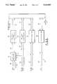
- FIG. 3is a schematic block diagram of the bus interface logic of the module of FIG. 2.
- FIG. 4is a schematic block diagram of the synchronization logic of FIG. 3.
- FIG. 5is a detailed schematic block diagram of the synchronization logic of FIG. 4 implemented in accordance with the invention.
- FIG. 6is a schematic block diagram of two processors interconnected by a system bus configured in accordance with the message communication protocol of the present invention.
- FIG. 7is a graphical illustration of mailbox location contents in accordance with the invention.
- FIG. 8is a chart of the contents of an interprocessor request block (IPRB) used in the message communication protocol of the present invention.
- IPRBinterprocessor request block
- FIG. 1a typical system topology of clustered work stations communicating via a LAN is depicted.
- the system of FIG. 1illustrates three work station clusters 10, 11, and 12 each connected locally via cluster communications and globally via a LAN 13.
- the LAN 13may, for example, comprise an 802.3 10 MB CSMA/CD LAN.
- Each of the clusters 10, 11, and 12is comprised of a master work station 14 coupled to one or more slave work stations 15 via cluster communications.
- Each of the clusters 10, 11, and 12is connected to the LAN 13 via a LAN interface module 16.
- the LAN interface module 16is connected physically adjacent the other modules of the master work station 14 and couples electrically thereto via the system or work station bus internal to the master work station 14.
- any of the slave work stations 15 connected to a master 14 with a LAN interface module 16can communicate over the LAN 13.
- LAN messagescan originate in any work station.
- the actual transmission of messages from the transport layer and belowis controlled by a processor and the circuitry in the LAN module 16.
- Higher levels of the protocolare the responsibility of the main processor within each of the work stations.
- the main processor in each of the master work stations 14 and each of the slave work stations 15is, for example, an 80186 class microprocessor with appropriate memory and support logic as well as circuitry for interfacing the 80186 to the other sections of the work station.
- the message communication synchronization of the present inventionis utilized in the system of FIG. 1 in synchronizing message transmission between the main processor of the master work station 14 and an auxilary processor in the LAN interface module 16 in a manner to be described.
- the LAN interface module 16comprises four sections of logic; viz, a LAN interface section 20, a RAM section 21, a processor section 22, (auxilliary processor) and a work station bus interface section 23.
- the LAN interface section 20couples to the LAN 13 in a conventional manner utilizing a standard bus schematically depicted at 24.
- the LAN interface section 20is comprised of industry standard VLSI chips for connecting to the 802.3 LAN.
- the VLSI componentsmay, for example, include an intel 82586 LAN co-processor, a Seeq 8002 Manchester Encoder and a National Semiconductor 8392 integrated transceiver.
- the transceiveris coupled to the LAN 13 for two way communication therebetween via the bus 24.
- the transceivercommunicates information from the LAN 13 to the 82586 co-processor.
- the co-processorcommunicates with the LAN 13 via the Manchester Encoder and the transceiver.
- the co-processor in the LAN interface section 20communicates with the RAM 21 via a bus 25.
- the RAM 21is a dual ported RAM with the bus 25 connected to one of the ports thereof.
- the LAN interface section 20operates in parallel with respect to the processor section 22 and the work station bus interface section 23. Communications between the 82586 co-processor of the LAN interface section 20 and the processor section 22 as well as the bus interface section 23 are via buffers in the dual ported RAM section 21. All commands and data to and from the co-processor are transmitted directly through the RAM section 21. Thus once initialized, the 82586 co-processor in the LAN interface section 20 and the processor section 22 operate completely in parallel and messages can be received or transmitted on the LAN 13 regardless of whether or not the processor section 22 is busy.
- the RAM section 21,comprising a conventional dual ported RAM and standard support circuitry, has one port thereof coupled to the LAN interface section 20 via the bus 25 and the second port thereof coupled to the processor 22 and the work station bus interface section 23 via a bus 26.
- Dual ported memoryis utilized in the LAN interface module 16 to support simultaneous access to memory by the processor section 22 and the LAN interface section 20.
- the LAN interface module 16therefore has the capability to simultaneously receive and process messages from the LAN 13.
- the RAM 21is designed with a fairly large capacity to support buffering of a large number of messages in situations where the main processor in the master work station 14 is busy handling other tasks. The design parameters are selected so that no messages from the LAN 13 are missed because of lack of response from the main processor.
- the processor section 22comprises an 80186 class microprocessor with the required memory chips, support logic and buffers for operating and interfacing the 80186 in the processor section 22 with respect to the other sections of the LAN interface module 16.
- ROM capabilities of the processor section 22are limited because operational software is downloaded from the main processor of the master work station 14.
- the processor section 22is connected for two way information flow to both the RAM section 21 at one of the ports thereof and to the work station bus interface section 23 via the bus 26.
- the work station bus interface section 23receives information from the processor section 22 and the RAM section 21 via the bus 26 and couples to a work station system internal interconnection bus 27 via a bus 28.
- the internal work station bus 27couples to the main processor 29 in the master work station 14.
- the work station bus interface section 23contains the logic necessary to interface the LAN module 16 to the main processor of the master work station 14 via the internal interconnection bus 27.
- the work station bus interface section 23contains apparatus utilized in the transmission of data as well as in the synchronization of the data communication in a manner to be described.
- the work station bus interface section 23comprises four blocks of logic; viz, module initialization logic 40, memory address mapping register logic 41, multiprocessor synchronization logic 42, and various buffers and transceivers for controlling the movement of data between the LAN interface module 16 and the work station system interconnection bus 27.
- the initialization logic 40communicates with the processor section 22 and the RAM section 21 of the LAN interface module 16 via a bus 43 and with the work station bus 27 via a bus 44.
- the initialization logic 40contains conventional hardware that is utilized during start up of the system to set various components thereof into an initial state.
- the initialization logic 40also contains standard hardware required to support the soft address protocol of the work station system.
- the initialization logic 40returns a device identification code to the main processor in the master work station 14 via the work station bus 27 and, in response thereto, the main processor defines the addresses to which the LAN interface module 16 will respond.
- the initialization logic 40includes the logic required to recognize the soft device addresses sent down from the main processor and to convey these addresses to the module 16 via the bus 43.
- Buffers and transceivers 45are included for controlling the movement of data to and from the processor section 22 and the RAM section 21 of the LAN interface module 16 via a data bus 46.
- the buffers and transceivers 45communicate the data to and from the work station bus 27 via a bus 47.
- the memory address mapping register logic 41is a combination of an adder and latches utilized to map local internal memory addresses of the module 16 to the memory address space of the intermodule system bus 27 for transmitting messages and data to other modules located in the master work station 14. Addresses eminating from the processor section 22 are applied to the mapping register logic 41 via an address bus 48 for mapping onto the system address bus.
- the data bus 46provides an input to the mapping register logic 41 for loading initial conditions for the address mapping operation. Appropriate buffers and transceivers 49 are included to control the transmission of the mapped addresses via buses 50 and 51 to the work station bus 27.
- the multiprocessor synchronization logic 42communicates with the processor section 22 via a bus 52 and with the work station bus 27 via a bus 53.
- the synchronization logic 42is utilized in the synchronization of data transfers across the work station internal bus 27 and the synchronization of communications between the processor section 22 and the main processor of the master work station 14.
- the address bus 48, data bus 46 and buses 43 and 52comprise the bus 26 of FIG. 2.
- the bus 28 of FIG. 2is comprised of the buses 44, 47, 51, and 53.
- the logic 42supports the generation of a hardware reset of the LAN module 16, a nonmaskable interrupt (NMI) at the LAN module 16 and several interrupt requests, for message communication synchronization, at both the LAN module 16 and the main processor in the master work station 14, in a manner to be explained. Details of the synchronization logic 42 will be described with respect to FIGS. 4 and 5.
- NMInonmaskable interrupt
- FIG. 4a schematic block diagram of the synchronization logic 42 (FIG. 3) is illustrated.
- the synchronization logic 42has the capability of synchronizing and controlling message communication among multiple processors connected to the work station system bus 27. Access to the system bus 27 by the processor 22 in the LAN interface module 16 is controlled by a circuit 60 of the Intel 8288/8289 class.
- the circuit 60comprises conventional logic to control data transfer across multiple bus systems. The circuit halts instructions or requests that are mapped by the processor 22 to the interconnection bus 27 until the bus has been physically granted to the LAN interface module 16.
- the circuit 60receives a bus request from the processor 22 on a line 61 and acknowledges to the processor 22, by a signal on a line 62, that the bus has been granted. In response to a request signal on the line 61 the circuit 60 provides the request to the bus on a line 63. The circuit 60 receives acknowledgement that the bus has been granted on a line 64.
- the LAN interface module 16(FIG. 2), via the interprocessor communications logic 65, receives three interrupts and transmits three interrupts over the work station system bus 27.
- interrupt requests to the LAN module 16are set by issuing an I/O write instruction over the system bus 27 to the base address of the module 16. The same procedure is utilized by the main processor in the master work station 14, or another module connected to the bus 27, to clear the request.
- Interrupt requestsare transmitted over the system bus 27 by locally executing I/O write instructions. These instructions are decoded locally and converted to actual bus requests. Interrupt requests into the module 16 are cleared by local I/O writes.
- the three interrupts that can be received by the LAN module 16are NMI, INT 1, and INT 3.
- INT 1 and INT 3are interrupt inputs to the processor 22 and are utilized for synchronization of normal message traffic in a manner to be described.
- the non-maskable interrupt requestis utilized for purposes such as bootstrapping the module 16.
- the LAN module 16via the interprocessor communications logic 65, generates an analogus set of interrupt requests; viz, a pseudo NMI line and two general purpose interrupt signals INT 1 and INT 2.
- the output NMImay be utilized, for example, to inform the main processor in the master work station 14 of any operational problems in the LAN module 16 and INT 1 and INT 2 may be utilized in the synchronization of message transmissions in accordance with the invention.
- the status of the interrupt request linesmay be monitored by issuing I/O read instructions either locally by the processor 22 or over the system bus 27 from the main processor in the master work station 14.
- the interprocessor communications logic 65provides the interrupt requests to the main processor in the master work station 14 on a bus 66 which connects to the work station system bus 27.
- the logic 65receives the input/output write and input/output read signals as well as bus address signals and bus data signals from the work station bus 27 via buses 67, 68, and 69 respectively.
- the interrupt requests to the local processor 22 from the logic 65are provided on a bus 70.
- the I/O write and read instructions as well as data and address signals from the local processor 22are provided to the logic 65 on buses 71 and 72 respectively.
- the logic 65provides an initialization reset command to the LAN interface section 20 and the processor section 22 of the LAN module 16 via a reset line 73. It is appreciated that the buses and lines 61, 62, and 70-73 comprise the bus 52 of FIG. 3. It is further appreciated that the buses and lines 63, 64, and 66-69 comprise the bus 53 of FIG. 3.
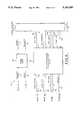
- the logic 65includes an input register 80 comprising a plurality of stages for storing the respective plurality of discrete control signals to be sent to the processor 22.
- the control signalsinclude the non-maskable interrupt request on a line 81, the INT 1 request on a line 82, the INT 3 request on a line 83 and the Reset request on the line 73.
- the lines 81-83correspond to the bus 70 of FIG. 4.
- the interrupt requests and the reset requestare set into the register 80 by connections to the associated respective data lines on the work station bus 27 via the data bus 69 through respective drivers 84-87.
- the discrete data signals provided by the drivers 84-87are set into the register 80 in response to a register enabling signal on a line 88.
- An I/O write instruction broadcast by the main processor in the master work station 14 on the work station bus 27is applied on the IOW line 67 to a device decoder 89 which responds thereto.
- the device decoder 89enables an address decoder 90. If the address sent down the bus 27 and received at the address bus 68 is the address assigned to the input register 80, the address decoder 90 enables the input register 80 via the line 88.
- the main processor in the master work station 14desires to send a discrete control signal, such as a message synchronizing interrupt or Reset, to the processor 22, the main processor broadcasts an I/O write instruction on the bus 27, the instruction including the address to which the address decoder 90 is responsive as well as data set to the desired control signal.
- the device decoder 89detects the broadcast I/O write instruction and the address decoder 90 is enable by the appropriate bus address, the input register 80 is enable to receive the data which sets in the desired discrete control signal.
- the main processormay broadcast the I/O write instruction by enabling a line on the bus 27 dedicated to I/O write.
- the main processormay broadcast, on plural lines, the operation code for the instruction.
- INT 1 and INT 3may be utilized for the message synchronizing interrupts required by the communications protocol.
- the Reset control discreteis provided to the processor 22 on the line 73 in the same manner as the message synchronizing interrupts.
- the message synchronizing interruptsmay be of the type where the main processor requests the attention of the auxillary processor 22 to transmit a message thereto or acknowledges to the auxillary processor 22 that a message has been received therefrom.
- the interprocessor communications logic 65also includes an output register 91 utilized in sending control discretes, such as interrupts, from the auxillary processor 22 to the main processor in the master work station 14 over the bus 27.
- the output register 91provides discrete control signals NMI on a line 92, INT 1 on a line 93 and INT 2 on line 94.
- the interrupt signals INT 1 and INT 2are interrupt inputs recognized by the main processor in the master work station 14 as message synchronizing interrupts. These interrupts are not necessarily the same as the interrupt signals provided by the input register 80 and hence are differently designated.
- the interrupt signals on the lines 92, 93, and 94are transmitted to respective lines of the work station bus 27 dedicated to these interrupts and connected to the associated interrupt inputs of the main processor.
- the interrupt signals on the lines 92, 93, and 94are transmitted to the corresponding lines of the work station bus 27 by respective drivers 95, 96, and 97 and the interrupt request bus 66.
- the data for setting the interrupts into the register 91are provided as part of an I/O write instruction from the processor 22 transmitted over the local bus 72.
- the data from the bus 72are inserted into the stages of the register 91 via respective drivers 98,99 and 100.
- the auxillary processor 22desires to send NMI, INT 1 or INT 2 to the main processor, the processor 22 issues an IOW command on the line 71 which enables a device decoder 101 responsive thereto.
- the device decoder 101In response to the I/O write command the device decoder 101 enables an address decoder 102 responsive to the address signal on the bus 72 from the auxillary processor 22.
- the auxillary processor 22desires to communicate with the output register 91, the I/O write instruction transmitted on the bus 72 contains the address to which the address decoder 102 responds.
- the output register 91When the address decoder 102 is energized, the output register 91 is enabled to receive the interrupt data sent with the I/O write instruction on the bus 72.
- the interprocessor communications logic 65is resident in one of the LAN interface modules of the system that includes the auxillary processor 22. Additional auxillary processors in, for example other LAN interface modules, may also be connected to the work station bus 27. Since the interrupt lines on the work station bus 27 connected to the main processor in the master work station 14 are unique, any one of the interprocessor communications logic blocks, such as the one illustrated in FIG. 5, may provide the interrupt NMI, INT 1 or INT 2 back to the main processor. A device decoder 103 and an address decoder 104 are included in the logic 65 to permit the main processor to determine from which auxillary processor the interrupt was transmitted.
- the main processorpolls the auxillary processors by broadcasting I/O read instructions containing the addresses of the various output registers.
- the decoder 103receives the I/O read instruction via the line 67, the decoder 103 enables the address decoder 104.
- the address decoder 104receives the address to which is it programmed to respond, transmitted from the main processor as part of the I/O read instructions on the address bus 68, the address decoder 104 enables drivers 105, 106, and 107.
- the main processorcan then examine the interrupt signals from the output register 91 to determine if one of them has been set. In this manner the main processor determines the auxillary processor 22 that originated the interrupt.
- the auxillary processor 22In operation when the auxillary processor 22 desires to send a message synchronizing interrupt to the main processor, the auxillary processor 22 generates an I/O write instruction containing the address to which the address decoder 102 responds and the interrupt data to be set into the output register 91.
- the processor 22places the I/O instruction on the local bus 26 (FIG. 2) which contains the data/address bus 72 and the I/O write instruction line 71.
- the interrupt to be transmitted to the main processoris set into the output register 91.
- the interruptis received by the main processor over the work station bus 27 and the source of the interrupt is identified by the main processor by polling the address decoders 104 by an I/O read instruction.
- the non-maskable interrupt on the line 92is utilized primarily to notify the main processor of a failure in the auxillary processor.
- the interrupt 1 and interrupt 2 signals on the lines 93 and 94are utilized for normal messaging in the manner described above with respect to the interrupt 1 and interrupt 3 signals on the lines 82 and 83 from the input register 80.
- the auxillary processormay want to inform the main processor that it has completed a task.
- the inventionhas been described in terms of an I/O instruction containing an address field designating the target device and a data field designating the particular control discrete to be transmitted, it is appreciated that the address together with the data signal may be considered as an address designating the particular control input port to which the communication is directed.
- the main processordesires to reset the auxillary processor 22, the main processor broadcasts an I/O write instruction containing an address field that designates the processor 22 as the target and a data field that designates the reset signal.
- the combination of the address field and the data fieldmay be considered as the address of the reset input to the processor 22.
- the above described message synchronization protocolmay be utilized in higher level message communication protocols.
- Data movementmay be controlled by providing the processor in control of the bus with the ability to control the movement of data by placing addresses and data on the bus and routing the data to common memory accessible to all processors connected to the bus.
- Data flow synchronizationmay be controlled at two levels. At the bus level, access to the bus and the common memory is controlled by higher level system bus arbitration logic and by a common memory controller. At a lower level the movement of messages by different processors is synchronized by providing each processor with the ability to receive and transmit synchronization interrupts over the system bus in the manner described above.
- each of the processorsis run by an operating system that controls the performance of various processes.
- a processrequires a function to be performed by the operating system, it submits a request to the operating system which in turn routes the request to the process capable of serving it.
- the process that has performed the functionsends a response back to the originating process to inform it that the operation has been completed. It is appreciated that with this mechanization, the process capable of responding to the request does not have to be resident on the processor that issues the request as long as there is sufficient intelligence within the operating system resident on the processor to route the request.
- each processorhas two processes (designated as agents) that are responsible for routing messages between processors, the Interprocessor communication (IPC) client and the IPC server.
- the function of the client agentis to receive requests from processes running on the same processor and to route them to the server agent of the processor where the function is to be performed.
- the client agentalso has the responsibility of returning a response back to the requesting process after the response has been received from the selected processor.
- the IPC server agentresponds to requests by other processors and routes them to the correct processes of the local operating system. It also receives the responses from the local operating system and routes them back to the appropriate IPC client.
- the service agentreceives requests from a client agent on another processor and submits it to the local operating system on behalf of the requestor. It also receives the response from the local operating system and routes it back to the client agent.
- a client agentalways communicates with a service agent and a service agent always communicates with a client agent.
- a mailbox mechanismis utilized for physically transmitting messages.
- Each processor on the system busis assigned two mailboxes (one for the client agent and one for the server agent) at a predefined address in memory accessible to all of the processors.
- each agentclient or service
- Each agenthas a mailbox associated therewith which is utilized by the owner agent as an outgoing mailbox into which the agent deposits messages to be delivered to another processor.
- Each agentalso has associated therewith a wake-up interrupt accessible over the work station bus 27 which permits other agents to bring to its attention that it is the addressee of a message to be found in the senders mailbox.
- the client agent wishing to transmit a request to a different processorwrites an abbreviated form of the message into its mailbox, specifies the desired processor in an addressee field of its mailbox and then generates an interrupt request to the appropriate server agent by issuing an I/O write command to the address of the attention signal for the appropriate processor.
- the interprocessor communications logic 65recognizes the appropriate I/O instructions on the system bus for requests coming in and generates the specific interrupts going out for the main processor, as described above.
- the server agent at the receiver processordetermines that it has a request pending by servicing the interrupt request and then scanning all of the mailboxes to determine the source of the request.
- the serverwill copy the request into the memory space of its processor and release the mailbox entry by clearing the address field.
- the server agentwill allocate memory in the common memory area and send a message to the client agent of the requesting processor asking it to copy the message to common memory before proceeding.
- controlis passed to the appropriate local process for servicing the request.
- controlis returned to the server agent and if necessary the results of the request are copied to the memory of the requesting processor (either directly if accessible to the system bus 27, or indirectly via the client agent if memory is not accessible to the system bus 27).
- the server agentthen creates a response message in its mailbox and sends an interrupt to the requesting agent informing it that the requested operation has been completed.
- Processors equipped with memories accessible to the system bus 27cannot write into memory space when that space is open to access from another processor. For example, once a processor puts a message in a mailbox and assigns a valid addressee code, it cannot modify the contents of the mailbox until the addressee field has been cleared.
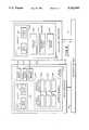
- the main processor 29includes a main memory 110 that includes a common memory portion 111.
- the common memory 111is accessible to the auxillary processor 22 as well as to any other processor on the work station bus 27.
- the main memory 110includes application software denoted as client 112.
- the client 112includes storage 113 for input data and storage 114 for output data.
- the processor 29includes a client agent 115 for communicating requests for service on a remote processor from any client resident on the processor 29. The requested service may, for example, be available at the auxillary processor 22.
- the client agentestablishes a request block 116 utilized in servicing the request.
- the request block 116will be explained in further detail hereafter.
- the auxillary processor 22includes a memory 117 storing service (server) software 118.
- the server 118may provide the service required by the client 112.
- the server 118includes an input data section 119 and an output data section 120.
- the processor 22may include numerous other services. It is further appreciated that both processors 29 and 22 may include multiple client applications and multiple services.
- the processor 22includes a service agent 121 to service the server 118 as well as any other services of the processor 22.
- the client agent 115communicates with the service agent 121 pursuant to a request from a client resident on the processor 29.
- the service agent 121may also communicate with the client agent 115 with respect to responses provided by the requested service resident on the processor 22.
- each processorwill include a client agent for handling the resident clients and a service agent for receiving service requests from remote processors.
- the client agent 115may communicate not only with the service agent 121 but also with the service agent of any other processor on the bus 27.
- the service agent 121may receive requests from the client agent 115 as well as from the client agent of any other processor on the bus 27. It is appreciated that multiple communications may be in progress simultaneously involving the same agent.
- the service agent 121may construct an interprocessor request block (IPRB) 122 in a manner to be explained.
- IPRBinterprocessor request block
- each agent of each processoris assigned a mailbox location in the common memory 111 for storing messages to be transmitted to another processor.
- the mailboxesare organized in an array of client mailboxes and an array of service mailboxes.
- the mailboxesare indexed by processor.
- the client array of mailboxesincludes mailboxes 123, 124, and 125.
- the service array of mailboxesincludes mailboxes 126, 127, and 128.
- the mailboxes 123 and 126may, for example, be indexed to the main processor 29 while the mailboxes 124 and 127 may be indexed to the auxillary processor 22.
- the mailboxes 125 and 128may be associated with a third processor (not shown) on the bus 27.
- the client mailbox 123is associated with the client agent 115 and the service mailbox 126 is associated with the service agent (not shown) of the main processor 29.
- the service mailbox 127is associated with the service agent 121 and the mailbox 124 is associated with the client agent (not shown) of the processor 22. Since all of the mailboxes are located in common memory 111 they are accessible to all of the agents in all of the processors on the bus 27.
- each of the mailboxes 123-128includes an addressee field designating the recipient agent with which an originator agent wishes to communicate. For example if the client agent 115 desires to communicate with the service agent 121 the client agent 115 will deposit in the addressee field of its mailbox 123 the identification of the processor 22. The client agent 115 then sends a wake-up interrupt to the processor 22 utilizing, preferably, the interrupt mechanism hereinabove described. The service agent 121 then scans the client mailboxes 123-125 to located the mailbox containing its address. The service agent 121 utilizes polling means 129 to effect this scanning procedure.
- the polling means 129is also utilized by the client agent (not shown) of the processor 22 to scan the service mailboxes 126-128.
- the processor 29includes polling means 130 for scanning the appropriate mailboxes in the common memory 111. It is appreciated that any processor on the work station bus 27 can access any of the mailboxes in the common memory 111 for reading and writing.
- the mailboxincludes an addressee field 140 utilized to store the identification of a message recipient processor.
- a value in field 140such as zero, is utilized to indicate that the mailbox is empty.
- the mailboxalso includes a pointer field 141 for storing the address of a request block such as the request block 116 or the IPRB 122.
- a data field 142is included to provide the size of a request block for the purpose of memory allocation.
- the mailbox of FIG. 7includes a function code field 143 for storing a Type Code indicating the type of message stored in the mailbox and the function or action to be taken by the message recipient.
- the request blockis the structure that carries requests and responses across the work station bus 27 from process to process.
- the request blockincludes a header that includes the size of the other portions of the block, the identification of the request originator and a function code to be performed by the service.
- the request blockincludes a section 151 containing a pointer to the input data of the client or the service and the memory size thereof as well as a section 152 containing a pointer to the output data and the memory size thereof.
- the section 151will contain a pointer to the input data 113 and the size thereof and the section 152 will contain a pointer to the output data 114 and the size thereof. If, however, an IPRB is constructed by the service agent 121 pursuant to a communication regarding the server 118, the section 151 will contain a pointer to the input data 119 and the size thereof and the section 152 will contain a pointer to the output data 120 and the size thereof.
- the client agent 115When the client 112 desires service resident on the processor 22 with respect to data in the output data field 114, the client agent 115 prepares request block 116 with the appropriate entries. The client agent 115 then determines if its mailbox 123 contains a cleared addressee field 140. If the addressee field 140 contains a valid address, the client agent 115 waits until it is cleared. When the addressee field is cleared the client agent 115 deposits a message into its mailbox 123 with the addressee field 140 identifying the service agent 121, the field 141 containing a pointer to the request block 116, the data field 142 containing the size of the request block and a function code in the field 143, to be later described, that notifies the service agent 121 that a new request is being made.
- the client agent 115then awakens the service agent 121 utilizing the interrupt mechanism previously described.
- the service agent 121scans the client mailboxes 123-125 to find the mailbox or mailboxes containing its address.
- the service agent 121then reads the contents of the mailbox into its queue for processing and thereafter erases the addressee field 140 of the mailbox that had contained its message.
- the mailbox of the client agent 115is thereby released for other communications.
- the service agent 121submits the request to the appropriate server resident on the processor 22 and provides a response back to the client agent by a mechanism similar to that described for the client agent to service agent communication.
- the function of the client agentis to submit requests from local processes to remote system services.
- a client agentis activated by receiving either a new request from a local process or by an interrupt from a service agent that is handling a request previously submitted.
- a client agentis responsive to the following Type Code interrupts: QUERY REQUEST BLOCK, QUERY REQUEST DATA, RESPONSE AVAILABLE, and SUBMIT RESPONSE.
- a service agentThe function of a service agent is to submit to the local operating system, a request from a remote process routed to the service agent by a client agent. The service agent further routes the response back to the client agent.
- a service agentis awakened by either an interrupt originating from a remote client agent or by a local response to an earlier request.
- a service agentis responsive to the following Type Code interrupts: NEW REQUEST AVAILABLE, REQUEST BLOCK COPIED, and SUBMIT REQUEST.
- the followingsets forth the actions performed by the client agent upon the submission of a new request and upon receiving the Type Code interrupts.
- a client agentUpon receipt of a new request, a client agent computes the size of the request block and stores a pointer to the request block and the size thereof in its mailbox. The client agent then interrupts the appropriate service agent with the Type Code NEW REQUEST AVAILABLE.
- the mailbox with its identification thereincontains a remote pointer to an IPRB.
- the client agentextracts from the IPRB the pointer to the local request block and copies the entire request block into the IPRB in the remote processor memory.
- the client agentstores the pointer to the IPRB in its mailbox and interrupts back to the service agent with a Type Code REQUEST BLOCK COPIED.
- the mailbox with its addresscontains a remote pointer to an IPRB.
- the associated service agenthas allocated memory for all of the input pointers of the request block and has set the pointers to refer to local memory.
- the client agentnow receives a pointer to the local request block and copies each of the data areas pointed to by the request input pointers from the local memory to the areas allocated by the service agent.
- the client agentthen stores the pointer to the IPRB in its mailbox and interrupts back to the service agent with a Type Code SUBMIT RESPONSE.
- the mailbox with its addresscontains a remote pointer to an IPRB.
- the requesthas been processed and a response is available.
- the client agentextracts the local pointer to the request block from the IPRB and copies all the data pointed to by the output pointer of the IPRB into the local areas pointed to by the corresponding input pointer of the local request block.
- the client agentissues the response to the requesting client and stores the pointer to the IPRB in its mailbox and interrupts back to the service agent with the Type Code RESPONSE SUBMITTED.
- the client agentWhen the client agent receives the interrupt SUBMIT RESPONSE, the corresponding service agent has performed all of the tasks pursuant to the communication.
- the mailbox with the address of the client agentcontains a pointer to the local request block.
- the client agentissues a response to the request to the client. Processing of the request is completed and there is no requirement, pursuant to the request, to have further communication with the service agent.
- the service agentWhen the service agent receives the interrupt NEW REQUEST AVAILABLE, a new request has been submitted by a client agent and the mailbox with the address of the service agent contains a remote pointer to a request block and the size of that block. From the size data in the mailbox, the service agent allocates sufficient memory to construct an IPRB and stores the identification of the originating processor and the pointer to the original request block. At this point the details of the communication between the service agent and the client agent depends upon the accessibility of the memory of the client to the service agent over the work station bus 27. When the memory of the client is accessible over the bus, the service agent copies the contents of the request block from the client processor into the IPRB at the service processor.
- the service agentFor each input pointer in the IPRB the service agent allocates sufficient memory and copies the data from the memory of the client changing the pointer to point to the local copy. For each output pointer, the service agent allocates sufficient memory and changes the pointer to refer to the local location. The request is then submitted to the local service.
- the service agentstores the pointer to the IPRB into its mailbox and interrupts the client agent with a Type Code QUERY REQUEST BLOCK.
- the client agentWhen a service agent receives the interrupt REQUEST BLOCK COPIED, the client agent has copied the request block to the local memory of the service processor and the mailbox contains a pointer to the local IPRB.
- the service processallocates memory for each input and output pointer and sets the pointers in the IPRB. If there are output pointers in the request block, the service agent stores the pointer to the IPRB in its mailbox and interrupts the client agent with the Type Code QUERY REQUEST DATA. If there are no output pointers in the request, the service agent submits the request locally.
- the client agentWhen the service agent receives the interrupt SUBMIT REQUEST, the client agent has copied the request data into the allocated memory areas and the mailbox contains a pointer to the local IPRB. The service agent then submits the request to the local service process.
- the service agentextracts the originating processor identification from the IPRB that is being resonded to and continues in one of three ways.
- the service agentstores the pointer to the original request block in the mailbox, de-allocates all of the areas pointed to by the request block input pointers, de-allocates the IPRB and interrupts the client agent with the Type Code SUBMIT RESPONSE.
- the service agentcopies back the response data to the memory of the client in the areas pointed to by the input pointers in the original request block.
- the service agentthen stores the pointer to the original request block in the mailbox, de-allocates all of the areas pointed to by the request block input pointers, de-allocates the IPRB and interrupts the client agent with the Type Code SUBMIT RESPONSE.
- the service agentstores the pointer to the IPRB in the mailbox and interrupts the client agent with the Type Code RESPONSE AVAILABLE.
- the client agentWhen the service agent receives the RESPONSE SUBMITTED interrupt, the client agent has copied the response data and submitted the response to the originator process.
- the mailboxcontains a pointer to an IPRB.
- the service agentde-allocates all the memory pointed to by the IPRB pointers and de-allocates the IPRB itself. No reply is necessary.
- the communicationis first described where the service agent has access to the client processor memory.
- the second situation describedis where the service agent does not have access to the client agent processor.
- Multiple events, such as those describedare interleaved in real time.
- the client agentWhen the client agent receives a request from a client where the service agent has access to the client processor memory, the client agent interrupts the service agent with NEW REQUEST AVAILABLE. In effecting this interrupt the client agent deposits into its mailbox the address of the service agent, a pointer to the request block, the size of the request block and the Type Code NEW REQUEST AVAILABLE. The service agent in response thereto copies the request block, copies the request data, and submits the request to the service. When the service has fulfilled the request, it submits the response to the service agent which copies back the response data into the client memory pursuant to the IPRB pointers. The service agent then interrupts the client agent with SUBMIT RESPONSE. This is effected by the service agent storing in its mailbox the address of the client agent, a pointer to the request block in the client memory and the Type Code SUBMIT RESPONSE. The client agent then provides the response to the client.
- the client agentWhen the client agent receives a request from the client where the service agent does not have access to the client processor memory, the client agent interrupts the service agent with NEW REQUEST AVAILABLE by storing in its mailbox the address of the service agent, a pointer to the request block in the client processor memory, the size of the request block, and the Type Code NEW REQUEST AVAILABLE.
- the service agentallocates space in the service memory for the IPRB and interrupts the client agent with QUERY REQUEST BLOCK. This is effected by the service agent storing in its mailbox the address of the client agent a pointer to the allocated IPRB memory space, the size of the space, and the Type Code QUERY REQUEST BLOCK.
- the client agentSince the client processor has access to the service processor memory the client agent copies back the request block into the IPRB allocated by the service processor and interrupts the service agent with REQUEST BLOCK COPIED.
- the service agentallocates memory for the input data and interrupts the client agent with QUERY REQUEST DATA.
- the client agentcopies back to the service processor the requisite data and interrupts the service agent with SUBMIT REQUEST.
- the service agentsubmits the request to the service and receives the response back therefrom.
- the service agentthen interrupts the client agent with RESPONSE DATA AVAILABLE.
- the client agentcopies the response data back from the service processor and submits the response to the client.
- the client agentthen interrupts the service agent with RESPONSE SUBMITTED.
- the service agentde-allocates the data storage space and the IPRB and the communication is completed.
- the originating agentwhen an originating agent desires to send a message to a recipient agent, the originating agent places a message in its mailbox, when the mailbox is empty, setting the address field thereof to the addressee and issuing a wake-up interrupt to the agent to which the message is addressed. If the mailbox is not empty within a predetermined delay interval the addressee of the previous message is declared nonresponsive and an error recovery procedure (not shown) is activated. The awakened agent scans all of the mailboxes of the opposite type and, from each mailbox containing its address, reads and saves the message therein for further processing. The recipient agent then empties the mailbox by resetting the address field. If a processor does not take a message addressed to it within the predefined delay the processor is declared non-functional.
- an originating agentutilizes its mailbox to communicate with plural recipient agents. Therefore a recipient agent must empty a mailbox containing its address as quickly as possible so as to release the mailbox for further use by the originator. The recipient agents queue the messages for subsequent processing.
- a recipient agentWhen two originating agents endeavor to send messages to the same recipient agent, there will not be any interference and no lock mechanism is required since each of the originating agents utilize their own mailboxes for the communication. Since many requests are processed at the same time, the request block unique to each request is utilized so that proper routing and processing is effected for each request.
- the above described communications protocolis relatively simple, compared to prior art communications protocols, which facilitates implementation and testing.
- the communications protocolprovides the system with many of the advantages associated with both loosely coupled and tightly coupled multiprocessor systems.
- the systemexhibits performance normally associated with tightly coupled systems because the time required to transmit messages is relatively short since message are passed at memory speeds.
- the processor independence, however, of a loosely coupled systemis retained since each processor runs its own operating system and must only communicate with another processor to access resources not available locally. It is appreciated that the main processor in the master work station 14 and the processor 22 in the LAN interface module 16 run completely different operating systems.
- the protocol of the present inventionhas been described in the implementation of an intelligent LAN interface module. It is appreciated that the protocol may also be utilized to readily implement other intelligent modules, such as an intelligent data communications module. There is no logical limit to the number of intelligent modules that can be connected to the main processor in the master work station 14 via the work station bus 27.
- the message synchronization protocol of the present inventionoffers advantages over the prior art in that it significantly reduces the number of direct interrupt lines on the system bus that would otherwise be required. Generally it would be impractical to provide direct interrupt communication between all processors sharing a system bus in a multiprocessor system. It is appreciated that the architecture described above is extensible so as to support multiple processors interconnected by a system bus.
- the present inventionprovides an efficient mechanism for extending the capabilities of a processor to permit it to reside on a local high speed bus with other processors and for these processors to communicate with one another in an efficient manner by means of message communication and synchronization.
- the inventionimplements an efficient message passing system in a multiprocessor environment.
- the present inventionmay be utilized for communication between a main processor and plural auxillary processors or between the auxillary processors themselves.
Landscapes
- Engineering & Computer Science (AREA)
- Theoretical Computer Science (AREA)
- Computer Hardware Design (AREA)
- Physics & Mathematics (AREA)
- General Engineering & Computer Science (AREA)
- General Physics & Mathematics (AREA)
- Computer Networks & Wireless Communication (AREA)
- Signal Processing (AREA)
- Computer Security & Cryptography (AREA)
- Microelectronics & Electronic Packaging (AREA)
- Software Systems (AREA)
- Multi Processors (AREA)
Abstract
Description
Claims (12)
Priority Applications (1)
| Application Number | Priority Date | Filing Date | Title |
|---|---|---|---|
| US07/771,889US5142683A (en) | 1987-03-09 | 1991-10-07 | Intercomputer communication control apparatus and method |
Applications Claiming Priority (3)
| Application Number | Priority Date | Filing Date | Title |
|---|---|---|---|
| US07/023,316US4866664A (en) | 1987-03-09 | 1987-03-09 | Intercomputer communication control apparatus & method |
| US6338487A | 1987-06-18 | 1987-06-18 | |
| US07/771,889US5142683A (en) | 1987-03-09 | 1991-10-07 | Intercomputer communication control apparatus and method |
Related Parent Applications (1)
| Application Number | Title | Priority Date | Filing Date |
|---|---|---|---|
| US6338487AContinuation | 1987-03-09 | 1987-06-18 |
Publications (1)
| Publication Number | Publication Date |
|---|---|
| US5142683Atrue US5142683A (en) | 1992-08-25 |
Family
ID=27362052
Family Applications (1)
| Application Number | Title | Priority Date | Filing Date |
|---|---|---|---|
| US07/771,889Expired - LifetimeUS5142683A (en) | 1987-03-09 | 1991-10-07 | Intercomputer communication control apparatus and method |
Country Status (1)
| Country | Link |
|---|---|
| US (1) | US5142683A (en) |
Cited By (95)
| Publication number | Priority date | Publication date | Assignee | Title |
|---|---|---|---|---|
| US5317739A (en)* | 1992-03-30 | 1994-05-31 | International Business Machines Corp. | Method and apparatus for coupling data processing systems |
| US5375219A (en)* | 1988-11-09 | 1994-12-20 | Fujitsu Limited | Common system with a plurality of processors using a common memory and utilizing an interrupt signal |
| US5375207A (en)* | 1988-10-31 | 1994-12-20 | Hewlett-Packard Company | Remote processing of a plurality of commands during a session between a first computer and a host computer |
| EP0640929A2 (en) | 1993-08-30 | 1995-03-01 | Advanced Micro Devices, Inc. | Inter-processor communication via post office RAM |
| US5423007A (en)* | 1989-05-31 | 1995-06-06 | Teldix Gmbh | Multiprocessor computer system having improved coupling arrangement for independently operating local processor systems |
| US5432715A (en)* | 1992-06-29 | 1995-07-11 | Hitachi, Ltd. | Computer system and monitoring method |
| US5444849A (en)* | 1991-09-09 | 1995-08-22 | Compaq Computer Corporation | Method for exchanging link level messages between a manager for a computer system and a remote facility asynchronously linked therewith |
| US5446841A (en)* | 1991-06-15 | 1995-08-29 | Hitachi, Ltd. | Multi-processor system having shared memory for storing the communication information used in communicating between processors |
| AU664741B2 (en)* | 1992-04-04 | 1995-11-30 | Alcatel N.V. | Voice and/or facsimile mail system |
| US5491799A (en)* | 1992-01-02 | 1996-02-13 | Amdahl Corporation | Communication interface for uniform communication among hardware and software units of a computer system |
| US5519883A (en)* | 1993-02-18 | 1996-05-21 | Unisys Corporation | Interbus interface module |
| US5572652A (en)* | 1994-04-04 | 1996-11-05 | The United States Of America As Represented By The Secretary Of The Navy | System and method for monitoring and controlling one or more computer sites |
| US5574863A (en)* | 1994-10-25 | 1996-11-12 | Hewlett-Packard Company | System for using mirrored memory as a robust communication path between dual disk storage controllers |
| US5590334A (en)* | 1994-03-30 | 1996-12-31 | Apple Computer, Inc | Object oriented message passing system and method |
| US5590338A (en)* | 1993-07-23 | 1996-12-31 | Dell Usa, L.P. | Combined multiprocessor interrupt controller and interprocessor communication mechanism |
| US5592624A (en)* | 1990-09-28 | 1997-01-07 | Fujitsu Limited | Data communication for controlling message transmission and reception among processing modules using information stored in descriptor to form a loosely coupled multiprocessing system |
| US5630165A (en)* | 1992-12-03 | 1997-05-13 | Advanced Micro Devices, Inc. | Servo system controlled by master and second processors through memory being accessed for read and write by processors in separate portions respectively |
| US5634035A (en)* | 1992-12-16 | 1997-05-27 | Siemens Business Communication Systems, Inc. | HDLC hardware engine and shared memory interface with access request/acknowledgement control and addressing scheme |
| US5644718A (en)* | 1994-11-10 | 1997-07-01 | At&T Corporation | Apparatus using circuit manager to associate a single circuit with each host application where the circuit is shared by a plurality of client applications |
| US5649184A (en)* | 1989-03-20 | 1997-07-15 | Fujitsu Limited | Symmetric/asymmetric shared processing operation in a tightly coupled multiprocessor |
| US5664198A (en)* | 1994-10-26 | 1997-09-02 | Intel Corporation | High speed access to PC card memory using interrupts |
| US5706516A (en)* | 1995-01-23 | 1998-01-06 | International Business Machines Corporation | System for communicating messages among agent processes |
| US5754781A (en)* | 1995-03-22 | 1998-05-19 | Nec Corporation | Data transfer controller device for controlling data transferred by and among separate clusters |
| US5790789A (en)* | 1996-08-02 | 1998-08-04 | Suarez; Larry | Method and architecture for the creation, control and deployment of services within a distributed computer environment |
| US5867161A (en)* | 1995-08-08 | 1999-02-02 | Walsh; Aaron E. | Uniform mnemonic associations of computer resources to graphical images |
| US5978594A (en)* | 1994-09-30 | 1999-11-02 | Bmc Software, Inc. | System for managing computer resources across a distributed computing environment by first reading discovery information about how to determine system resources presence |
| US6041417A (en)* | 1998-06-04 | 2000-03-21 | Hewlett-Packard Company | Method and apparatus for synchronizing data received in an accelerated graphics port of a graphics memory system |
| US6067086A (en)* | 1995-08-08 | 2000-05-23 | Walsh; Aaron E. | Uniform mnemonic associations of computer resources to graphical images |
| EP1061454A1 (en)* | 1999-06-14 | 2000-12-20 | Abb Research Ltd. | Method for synchronizing devices to a computer bus |
| WO2000036509A3 (en)* | 1998-12-18 | 2001-04-19 | Unisys Corp | Computer system and method for operating multiple operating systems in different partitions of the computer system and for allowing the different partitions to communicate with one another through shared memory |
| US20010037410A1 (en)* | 2000-04-03 | 2001-11-01 | Gardner Andrew J. | Interrupt throttling for inter-processor communications |
| US20020053017A1 (en)* | 2000-09-01 | 2002-05-02 | Adiletta Matthew J. | Register instructions for a multithreaded processor |
| US20020056037A1 (en)* | 2000-08-31 | 2002-05-09 | Gilbert Wolrich | Method and apparatus for providing large register address space while maximizing cycletime performance for a multi-threaded register file set |
| US6519686B2 (en)* | 1998-01-05 | 2003-02-11 | Intel Corporation | Information streaming in a multi-process system using shared memory |
| US20030041166A1 (en)* | 2001-08-20 | 2003-02-27 | Richard Williamson | Method for transmitting data over a physical medium |
| US20030041216A1 (en)* | 2001-08-27 | 2003-02-27 | Rosenbluth Mark B. | Mechanism for providing early coherency detection to enable high performance memory updates in a latency sensitive multithreaded environment |
| US20030046488A1 (en)* | 2001-08-27 | 2003-03-06 | Rosenbluth Mark B. | Software controlled content addressable memory in a general purpose execution datapath |
| US20030088318A1 (en)* | 2001-10-25 | 2003-05-08 | Fuji Xerox Co., Ltd. | Device control system |
| US20030110166A1 (en)* | 2001-12-12 | 2003-06-12 | Gilbert Wolrich | Queue management |
| US20030115347A1 (en)* | 2001-12-18 | 2003-06-19 | Gilbert Wolrich | Control mechanisms for enqueue and dequeue operations in a pipelined network processor |
| US20030115426A1 (en)* | 2001-12-17 | 2003-06-19 | Rosenbluth Mark B. | Congestion management for high speed queuing |
| US20030126347A1 (en)* | 2001-12-27 | 2003-07-03 | Choon-Seng Tan | Data array having redundancy messaging between array controllers over the host bus |
| US20030131022A1 (en)* | 2002-01-04 | 2003-07-10 | Gilbert Wolrich | Queue arrays in network devices |
| US20030131198A1 (en)* | 2002-01-07 | 2003-07-10 | Gilbert Wolrich | Queue array caching in network devices |
| US20030131173A1 (en)* | 2002-01-09 | 2003-07-10 | International Business Machines Corporation | Method and apparatus for host messaging unit for peripheral component interconnect busmaster devices |
| US20030135683A1 (en)* | 2002-01-11 | 2003-07-17 | International Business Machines Corporation | Method, system, and program for testing a bus interface |
| US20030135351A1 (en)* | 2002-01-17 | 2003-07-17 | Wilkinson Hugh M. | Functional pipelines |
| US20030145173A1 (en)* | 2002-01-25 | 2003-07-31 | Wilkinson Hugh M. | Context pipelines |
| US20030147409A1 (en)* | 2002-02-01 | 2003-08-07 | Gilbert Wolrich | Processing data packets |
| US20030191866A1 (en)* | 2002-04-03 | 2003-10-09 | Gilbert Wolrich | Registers for data transfers |
| US6694380B1 (en)* | 1999-12-27 | 2004-02-17 | Intel Corporation | Mapping requests from a processing unit that uses memory-mapped input-output space |
| US6708246B1 (en)* | 1999-12-27 | 2004-03-16 | Renesas Technology Corp. | Signal processing device with bus ownership control function |
| US20040073728A1 (en)* | 1999-12-28 | 2004-04-15 | Intel Corporation, A California Corporation | Optimizations to receive packet status from FIFO bus |
| US20040109369A1 (en)* | 1999-12-28 | 2004-06-10 | Intel Corporation, A California Corporation | Scratchpad memory |
| US20040139290A1 (en)* | 2003-01-10 | 2004-07-15 | Gilbert Wolrich | Memory interleaving |
| US20040205747A1 (en)* | 2000-12-21 | 2004-10-14 | Debra Bernstein | Breakpoint for parallel hardware threads in multithreaded processor |
| US20040230980A1 (en)* | 1999-03-10 | 2004-11-18 | Masahiro Koyama | Decentralized control system for network connection |
| US20050027914A1 (en)* | 2003-07-31 | 2005-02-03 | Per Hammalund | Inter-processor interrupts |
| US6976095B1 (en) | 1999-12-30 | 2005-12-13 | Intel Corporation | Port blocking technique for maintaining receive packet ordering for a multiple ethernet port switch |
| US6983350B1 (en) | 1999-08-31 | 2006-01-03 | Intel Corporation | SDRAM controller for parallel processor architecture |
| US7111296B2 (en) | 1999-12-28 | 2006-09-19 | Intel Corporation | Thread signaling in multi-threaded processor |
| US7126952B2 (en) | 2001-09-28 | 2006-10-24 | Intel Corporation | Multiprotocol decapsulation/encapsulation control structure and packet protocol conversion method |
| US7191309B1 (en) | 1999-09-01 | 2007-03-13 | Intel Corporation | Double shift instruction for micro engine used in multithreaded parallel processor architecture |
| US7191321B2 (en) | 1999-08-31 | 2007-03-13 | Intel Corporation | Microengine for parallel processor architecture |
| US7213099B2 (en) | 2003-12-30 | 2007-05-01 | Intel Corporation | Method and apparatus utilizing non-uniformly distributed DRAM configurations and to detect in-range memory address matches |
| US20070104204A1 (en)* | 2005-11-08 | 2007-05-10 | Brokenshire Daniel A | Apparatus and method for performing externally assisted calls in a heterogeneous processing complex |
| US7225281B2 (en) | 2001-08-27 | 2007-05-29 | Intel Corporation | Multiprocessor infrastructure for providing flexible bandwidth allocation via multiple instantiations of separate data buses, control buses and support mechanisms |
| US20070234021A1 (en)* | 2006-03-30 | 2007-10-04 | Silicon Image, Inc. | Inter-port communication in a multi-port memory device |
| US20070233938A1 (en)* | 2006-03-30 | 2007-10-04 | Silicon Image, Inc. | Shared nonvolatile memory architecture |
| US7305500B2 (en) | 1999-08-31 | 2007-12-04 | Intel Corporation | Sram controller for parallel processor architecture including a read queue and an order queue for handling requests |
| US7328289B2 (en) | 1999-12-30 | 2008-02-05 | Intel Corporation | Communication between processors |
| US7337275B2 (en) | 2002-08-13 | 2008-02-26 | Intel Corporation | Free list and ring data structure management |
| US7352769B2 (en) | 2002-09-12 | 2008-04-01 | Intel Corporation | Multiple calendar schedule reservation structure and method |
| US7421572B1 (en) | 1999-09-01 | 2008-09-02 | Intel Corporation | Branch instruction for processor with branching dependent on a specified bit in a register |
| US20080244612A1 (en)* | 2007-03-29 | 2008-10-02 | Masana Murase | Method, system, and computer program product for invoking externally assisted calls from an isolated environment |
| US7434221B2 (en) | 1999-12-30 | 2008-10-07 | Intel Corporation | Multi-threaded sequenced receive for fast network port stream of packets |
| US7433307B2 (en) | 2002-11-05 | 2008-10-07 | Intel Corporation | Flow control in a network environment |
| US7443836B2 (en) | 2003-06-16 | 2008-10-28 | Intel Corporation | Processing a data packet |
| US7471688B2 (en) | 2002-06-18 | 2008-12-30 | Intel Corporation | Scheduling system for transmission of cells to ATM virtual circuits and DSL ports |
| US20090013113A1 (en)* | 2007-07-03 | 2009-01-08 | Henry Russell J | Methods and systems for interprocessor message exchange between devices using only write bus transactions |
| US7480706B1 (en) | 1999-12-30 | 2009-01-20 | Intel Corporation | Multi-threaded round-robin receive for fast network port |
| US7487505B2 (en) | 2001-08-27 | 2009-02-03 | Intel Corporation | Multithreaded microprocessor with register allocation based on number of active threads |
| US20090089545A1 (en)* | 2007-09-28 | 2009-04-02 | Samsung Electronics Co., Ltd. | Multi processor system having multiport semiconductor memory with processor wake-up function |
| US7546444B1 (en) | 1999-09-01 | 2009-06-09 | Intel Corporation | Register set used in multithreaded parallel processor architecture |
| US7610451B2 (en) | 2002-01-25 | 2009-10-27 | Intel Corporation | Data transfer mechanism using unidirectional pull bus and push bus |
| US7620702B1 (en) | 1999-12-28 | 2009-11-17 | Intel Corporation | Providing real-time control data for a network processor |
| US20100005201A1 (en)* | 2008-07-02 | 2010-01-07 | Seiko Epson Corporation | Multi-processor system and fluid ejecting apparatus having the same |
| US20100095040A1 (en)* | 2008-10-12 | 2010-04-15 | Fujitsu Limited | Multi-core processor, control method thereof, and information processing apparatus |
| US7751402B2 (en) | 1999-12-29 | 2010-07-06 | Intel Corporation | Method and apparatus for gigabit packet assignment for multithreaded packet processing |
| USRE41849E1 (en) | 1999-12-22 | 2010-10-19 | Intel Corporation | Parallel multi-threaded processing |
| US20110047310A1 (en)* | 2008-04-28 | 2011-02-24 | Bonola Thomas J | Method and System for Generating and Delivering Inter-Processor Interrupts in a Multi-Core Processor and in Ceterain Shared Memory Multi-Processor Systems |
| US7940706B2 (en) | 2001-10-01 | 2011-05-10 | International Business Machines Corporation | Controlling the state of duplexing of coupling facility structures |
| US9229886B2 (en)* | 2010-04-30 | 2016-01-05 | Hewlett Packard Enterprise Development Lp | Management data transfer between processors |
| CN110858187A (en)* | 2018-08-23 | 2020-03-03 | 慧荣科技股份有限公司 | Multiprocessor system with distributed mailbox structure and method for checking processor errors |
| CN113806283A (en)* | 2020-06-11 | 2021-12-17 | Oppo广东移动通信有限公司 | Processing chip, circuit board, electronic equipment and data transmission method |
Citations (12)
| Publication number | Priority date | Publication date | Assignee | Title |
|---|---|---|---|---|
| US4365294A (en)* | 1980-04-10 | 1982-12-21 | Nizdorf Computer Corporation | Modular terminal system using a common bus |
| US4402046A (en)* | 1978-12-21 | 1983-08-30 | Intel Corporation | Interprocessor communication system |
| US4404628A (en)* | 1979-12-03 | 1983-09-13 | Honeywell Information Systems Inc. | Multiprocessor system |
| US4488231A (en)* | 1980-09-29 | 1984-12-11 | Honeywell Information Systems Inc. | Communication multiplexer having dual microprocessors |
| US4494185A (en)* | 1981-04-16 | 1985-01-15 | Ncr Corporation | Data processing system employing broadcast packet switching |
| US4536838A (en)* | 1983-03-24 | 1985-08-20 | Mds Qantel, Inc. | Multi-processor system with communication controller using poll flags for non-contentious slot reservation |
| US4564901A (en)* | 1983-07-21 | 1986-01-14 | Burroughs Corporation | Method of performing a sequence of related activities via multiple asynchronously intercoupled digital processors |
| US4769771A (en)* | 1984-01-20 | 1988-09-06 | U.S. Philips Corporation | Multiprocessor system comprising a plurality of data processors which are interconnected by a communication network |
| US4777595A (en)* | 1982-05-07 | 1988-10-11 | Digital Equipment Corporation | Apparatus for transferring blocks of information from one node to a second node in a computer network |
| US4835674A (en)* | 1986-07-28 | 1989-05-30 | Bull Hn Information Systems Inc. | Computer network system for multiple processing elements |
| US4851988A (en)* | 1986-03-31 | 1989-07-25 | Wang Laboratories, Inc. | Loosely-coupled computer system using global identifiers to identify mailboxes and volumes |
| US4862354A (en)* | 1985-05-07 | 1989-08-29 | Honeywell Bull Italia S.P.A. | Multiprocessor system with interrupt notification and verification unit |
- 1991
- 1991-10-07USUS07/771,889patent/US5142683A/ennot_activeExpired - Lifetime
Patent Citations (12)
| Publication number | Priority date | Publication date | Assignee | Title |
|---|---|---|---|---|
| US4402046A (en)* | 1978-12-21 | 1983-08-30 | Intel Corporation | Interprocessor communication system |
| US4404628A (en)* | 1979-12-03 | 1983-09-13 | Honeywell Information Systems Inc. | Multiprocessor system |
| US4365294A (en)* | 1980-04-10 | 1982-12-21 | Nizdorf Computer Corporation | Modular terminal system using a common bus |
| US4488231A (en)* | 1980-09-29 | 1984-12-11 | Honeywell Information Systems Inc. | Communication multiplexer having dual microprocessors |
| US4494185A (en)* | 1981-04-16 | 1985-01-15 | Ncr Corporation | Data processing system employing broadcast packet switching |
| US4777595A (en)* | 1982-05-07 | 1988-10-11 | Digital Equipment Corporation | Apparatus for transferring blocks of information from one node to a second node in a computer network |
| US4536838A (en)* | 1983-03-24 | 1985-08-20 | Mds Qantel, Inc. | Multi-processor system with communication controller using poll flags for non-contentious slot reservation |
| US4564901A (en)* | 1983-07-21 | 1986-01-14 | Burroughs Corporation | Method of performing a sequence of related activities via multiple asynchronously intercoupled digital processors |
| US4769771A (en)* | 1984-01-20 | 1988-09-06 | U.S. Philips Corporation | Multiprocessor system comprising a plurality of data processors which are interconnected by a communication network |
| US4862354A (en)* | 1985-05-07 | 1989-08-29 | Honeywell Bull Italia S.P.A. | Multiprocessor system with interrupt notification and verification unit |
| US4851988A (en)* | 1986-03-31 | 1989-07-25 | Wang Laboratories, Inc. | Loosely-coupled computer system using global identifiers to identify mailboxes and volumes |
| US4835674A (en)* | 1986-07-28 | 1989-05-30 | Bull Hn Information Systems Inc. | Computer network system for multiple processing elements |
Non-Patent Citations (3)
| Title |
|---|
| First Annual Phonix Conference on Computers & Communications, Bitner, D. P., Inter Processor Communication in a Distributed Processing System, 1982, pp. 263 266.* |
| First Annual Phonix Conference on Computers & Communications, Bitner, D. P., Inter-Processor Communication in a Distributed Processing System, 1982, pp. 263-266. |
| M. D. Rap et al., Microstandards, IEEE Micro, vol. 6, No. 3, Jun. 1986, p. 1296.* |
Cited By (157)
| Publication number | Priority date | Publication date | Assignee | Title |
|---|---|---|---|---|
| US5375207A (en)* | 1988-10-31 | 1994-12-20 | Hewlett-Packard Company | Remote processing of a plurality of commands during a session between a first computer and a host computer |
| US5375219A (en)* | 1988-11-09 | 1994-12-20 | Fujitsu Limited | Common system with a plurality of processors using a common memory and utilizing an interrupt signal |
| US5649184A (en)* | 1989-03-20 | 1997-07-15 | Fujitsu Limited | Symmetric/asymmetric shared processing operation in a tightly coupled multiprocessor |
| US5423007A (en)* | 1989-05-31 | 1995-06-06 | Teldix Gmbh | Multiprocessor computer system having improved coupling arrangement for independently operating local processor systems |
| US5592624A (en)* | 1990-09-28 | 1997-01-07 | Fujitsu Limited | Data communication for controlling message transmission and reception among processing modules using information stored in descriptor to form a loosely coupled multiprocessing system |
| US5446841A (en)* | 1991-06-15 | 1995-08-29 | Hitachi, Ltd. | Multi-processor system having shared memory for storing the communication information used in communicating between processors |
| US5444849A (en)* | 1991-09-09 | 1995-08-22 | Compaq Computer Corporation | Method for exchanging link level messages between a manager for a computer system and a remote facility asynchronously linked therewith |
| US5491799A (en)* | 1992-01-02 | 1996-02-13 | Amdahl Corporation | Communication interface for uniform communication among hardware and software units of a computer system |
| US5317739A (en)* | 1992-03-30 | 1994-05-31 | International Business Machines Corp. | Method and apparatus for coupling data processing systems |
| AU664741B2 (en)* | 1992-04-04 | 1995-11-30 | Alcatel N.V. | Voice and/or facsimile mail system |
| US5432715A (en)* | 1992-06-29 | 1995-07-11 | Hitachi, Ltd. | Computer system and monitoring method |
| US5771394A (en)* | 1992-12-03 | 1998-06-23 | Advanced Micro Devices, Inc. | Apparatus having signal processors for providing respective signals to master processor to notify that newly written data can be obtained from one or more memories |
| US5771393A (en)* | 1992-12-03 | 1998-06-23 | Advanced Micro Devices, Inc. | Servo loop control apparatus having master processor to control the apparatus and second processor dedicated to specific preprogrammed servo loop control tasks |
| US5630165A (en)* | 1992-12-03 | 1997-05-13 | Advanced Micro Devices, Inc. | Servo system controlled by master and second processors through memory being accessed for read and write by processors in separate portions respectively |
| US5634035A (en)* | 1992-12-16 | 1997-05-27 | Siemens Business Communication Systems, Inc. | HDLC hardware engine and shared memory interface with access request/acknowledgement control and addressing scheme |
| US5519883A (en)* | 1993-02-18 | 1996-05-21 | Unisys Corporation | Interbus interface module |
| US5590338A (en)* | 1993-07-23 | 1996-12-31 | Dell Usa, L.P. | Combined multiprocessor interrupt controller and interprocessor communication mechanism |
| EP0640929A2 (en) | 1993-08-30 | 1995-03-01 | Advanced Micro Devices, Inc. | Inter-processor communication via post office RAM |
| US5608873A (en)* | 1993-08-30 | 1997-03-04 | Advanced Micro Devices, Inc. | Device and method for interprocessor communication using mailboxes owned by processor devices |
| US5590334A (en)* | 1994-03-30 | 1996-12-31 | Apple Computer, Inc | Object oriented message passing system and method |
| US5572652A (en)* | 1994-04-04 | 1996-11-05 | The United States Of America As Represented By The Secretary Of The Navy | System and method for monitoring and controlling one or more computer sites |
| US5978594A (en)* | 1994-09-30 | 1999-11-02 | Bmc Software, Inc. | System for managing computer resources across a distributed computing environment by first reading discovery information about how to determine system resources presence |
| US5574863A (en)* | 1994-10-25 | 1996-11-12 | Hewlett-Packard Company | System for using mirrored memory as a robust communication path between dual disk storage controllers |
| US5664198A (en)* | 1994-10-26 | 1997-09-02 | Intel Corporation | High speed access to PC card memory using interrupts |
| US5644718A (en)* | 1994-11-10 | 1997-07-01 | At&T Corporation | Apparatus using circuit manager to associate a single circuit with each host application where the circuit is shared by a plurality of client applications |
| US5706516A (en)* | 1995-01-23 | 1998-01-06 | International Business Machines Corporation | System for communicating messages among agent processes |
| US5754781A (en)* | 1995-03-22 | 1998-05-19 | Nec Corporation | Data transfer controller device for controlling data transferred by and among separate clusters |
| US5867161A (en)* | 1995-08-08 | 1999-02-02 | Walsh; Aaron E. | Uniform mnemonic associations of computer resources to graphical images |
| US6067086A (en)* | 1995-08-08 | 2000-05-23 | Walsh; Aaron E. | Uniform mnemonic associations of computer resources to graphical images |
| US5790789A (en)* | 1996-08-02 | 1998-08-04 | Suarez; Larry | Method and architecture for the creation, control and deployment of services within a distributed computer environment |
| US6519686B2 (en)* | 1998-01-05 | 2003-02-11 | Intel Corporation | Information streaming in a multi-process system using shared memory |
| US6041417A (en)* | 1998-06-04 | 2000-03-21 | Hewlett-Packard Company | Method and apparatus for synchronizing data received in an accelerated graphics port of a graphics memory system |
| US7571440B2 (en) | 1998-07-23 | 2009-08-04 | Unisys Corporation | System and method for emulating network communications between partitions of a computer system |
| US6314501B1 (en) | 1998-07-23 | 2001-11-06 | Unisys Corporation | Computer system and method for operating multiple operating systems in different partitions of the computer system and for allowing the different partitions to communicate with one another through shared memory |
| US9253046B2 (en) | 1998-09-10 | 2016-02-02 | International Business Machines Corporation | Controlling the state of duplexing of coupling facility structures |
| US9860315B2 (en) | 1998-09-10 | 2018-01-02 | International Business Machines Corporation | Controlling the state of duplexing of coupling facility structures |
| US9565013B2 (en) | 1998-09-10 | 2017-02-07 | International Business Machines Corporation | Controlling the state of duplexing of coupling facility structures |
| WO2000036509A3 (en)* | 1998-12-18 | 2001-04-19 | Unisys Corp | Computer system and method for operating multiple operating systems in different partitions of the computer system and for allowing the different partitions to communicate with one another through shared memory |
| US7519968B2 (en) | 1999-03-10 | 2009-04-14 | Hitachi, Ltd. | Decentralized control system for network connection |
| US20040230980A1 (en)* | 1999-03-10 | 2004-11-18 | Masahiro Koyama | Decentralized control system for network connection |
| WO2000077651A1 (en)* | 1999-06-14 | 2000-12-21 | Abb Research Ltd. | Method for synchronizing devices in a bus |
| EP1061454A1 (en)* | 1999-06-14 | 2000-12-20 | Abb Research Ltd. | Method for synchronizing devices to a computer bus |
| US7305500B2 (en) | 1999-08-31 | 2007-12-04 | Intel Corporation | Sram controller for parallel processor architecture including a read queue and an order queue for handling requests |
| US6983350B1 (en) | 1999-08-31 | 2006-01-03 | Intel Corporation | SDRAM controller for parallel processor architecture |
| US7424579B2 (en) | 1999-08-31 | 2008-09-09 | Intel Corporation | Memory controller for processor having multiple multithreaded programmable units |
| US7191321B2 (en) | 1999-08-31 | 2007-03-13 | Intel Corporation | Microengine for parallel processor architecture |
| US8316191B2 (en) | 1999-08-31 | 2012-11-20 | Intel Corporation | Memory controllers for processor having multiple programmable units |
| US7546444B1 (en) | 1999-09-01 | 2009-06-09 | Intel Corporation | Register set used in multithreaded parallel processor architecture |
| US7191309B1 (en) | 1999-09-01 | 2007-03-13 | Intel Corporation | Double shift instruction for micro engine used in multithreaded parallel processor architecture |
| US7421572B1 (en) | 1999-09-01 | 2008-09-02 | Intel Corporation | Branch instruction for processor with branching dependent on a specified bit in a register |
| US7991983B2 (en) | 1999-09-01 | 2011-08-02 | Intel Corporation | Register set used in multithreaded parallel processor architecture |
| USRE41849E1 (en) | 1999-12-22 | 2010-10-19 | Intel Corporation | Parallel multi-threaded processing |
| US6694380B1 (en)* | 1999-12-27 | 2004-02-17 | Intel Corporation | Mapping requests from a processing unit that uses memory-mapped input-output space |
| US8738886B2 (en) | 1999-12-27 | 2014-05-27 | Intel Corporation | Memory mapping in a processor having multiple programmable units |
| US9830285B2 (en) | 1999-12-27 | 2017-11-28 | Intel Corporation | Memory mapping in a processor having multiple programmable units |
| US9830284B2 (en) | 1999-12-27 | 2017-11-28 | Intel Corporation | Memory mapping in a processor having multiple programmable units |
| US6708246B1 (en)* | 1999-12-27 | 2004-03-16 | Renesas Technology Corp. | Signal processing device with bus ownership control function |
| US9824038B2 (en) | 1999-12-27 | 2017-11-21 | Intel Corporation | Memory mapping in a processor having multiple programmable units |
| US9824037B2 (en) | 1999-12-27 | 2017-11-21 | Intel Corporation | Memory mapping in a processor having multiple programmable units |
| US9128818B2 (en) | 1999-12-27 | 2015-09-08 | Intel Corporation | Memory mapping in a processor having multiple programmable units |
| US7620702B1 (en) | 1999-12-28 | 2009-11-17 | Intel Corporation | Providing real-time control data for a network processor |
| US7111296B2 (en) | 1999-12-28 | 2006-09-19 | Intel Corporation | Thread signaling in multi-threaded processor |
| US20040109369A1 (en)* | 1999-12-28 | 2004-06-10 | Intel Corporation, A California Corporation | Scratchpad memory |
| US20040073728A1 (en)* | 1999-12-28 | 2004-04-15 | Intel Corporation, A California Corporation | Optimizations to receive packet status from FIFO bus |
| US6876561B2 (en) | 1999-12-28 | 2005-04-05 | Intel Corporation | Scratchpad memory |
| US6895457B2 (en) | 1999-12-28 | 2005-05-17 | Intel Corporation | Bus interface with a first-in-first-out memory |
| US7751402B2 (en) | 1999-12-29 | 2010-07-06 | Intel Corporation | Method and apparatus for gigabit packet assignment for multithreaded packet processing |
| US7434221B2 (en) | 1999-12-30 | 2008-10-07 | Intel Corporation | Multi-threaded sequenced receive for fast network port stream of packets |
| US7480706B1 (en) | 1999-12-30 | 2009-01-20 | Intel Corporation | Multi-threaded round-robin receive for fast network port |
| US6976095B1 (en) | 1999-12-30 | 2005-12-13 | Intel Corporation | Port blocking technique for maintaining receive packet ordering for a multiple ethernet port switch |
| US7328289B2 (en) | 1999-12-30 | 2008-02-05 | Intel Corporation | Communication between processors |
| US6931643B2 (en)* | 2000-04-03 | 2005-08-16 | Texas Instruments Incorporated | Interrupt throttling for inter-processor communications |
| US20010037410A1 (en)* | 2000-04-03 | 2001-11-01 | Gardner Andrew J. | Interrupt throttling for inter-processor communications |
| US7681018B2 (en) | 2000-08-31 | 2010-03-16 | Intel Corporation | Method and apparatus for providing large register address space while maximizing cycletime performance for a multi-threaded register file set |
| US20020056037A1 (en)* | 2000-08-31 | 2002-05-09 | Gilbert Wolrich | Method and apparatus for providing large register address space while maximizing cycletime performance for a multi-threaded register file set |
| US7743235B2 (en) | 2000-08-31 | 2010-06-22 | Intel Corporation | Processor having a dedicated hash unit integrated within |
| US20020053017A1 (en)* | 2000-09-01 | 2002-05-02 | Adiletta Matthew J. | Register instructions for a multithreaded processor |
| US20040205747A1 (en)* | 2000-12-21 | 2004-10-14 | Debra Bernstein | Breakpoint for parallel hardware threads in multithreaded processor |
| US7020871B2 (en) | 2000-12-21 | 2006-03-28 | Intel Corporation | Breakpoint method for parallel hardware threads in multithreaded processor |
| US20030041166A1 (en)* | 2001-08-20 | 2003-02-27 | Richard Williamson | Method for transmitting data over a physical medium |
| US7225281B2 (en) | 2001-08-27 | 2007-05-29 | Intel Corporation | Multiprocessor infrastructure for providing flexible bandwidth allocation via multiple instantiations of separate data buses, control buses and support mechanisms |
| US7487505B2 (en) | 2001-08-27 | 2009-02-03 | Intel Corporation | Multithreaded microprocessor with register allocation based on number of active threads |
| US6868476B2 (en) | 2001-08-27 | 2005-03-15 | Intel Corporation | Software controlled content addressable memory in a general purpose execution datapath |
| US7246197B2 (en) | 2001-08-27 | 2007-07-17 | Intel Corporation | Software controlled content addressable memory in a general purpose execution datapath |
| US20030041216A1 (en)* | 2001-08-27 | 2003-02-27 | Rosenbluth Mark B. | Mechanism for providing early coherency detection to enable high performance memory updates in a latency sensitive multithreaded environment |
| US7216204B2 (en) | 2001-08-27 | 2007-05-08 | Intel Corporation | Mechanism for providing early coherency detection to enable high performance memory updates in a latency sensitive multithreaded environment |
| US20030046488A1 (en)* | 2001-08-27 | 2003-03-06 | Rosenbluth Mark B. | Software controlled content addressable memory in a general purpose execution datapath |
| US7126952B2 (en) | 2001-09-28 | 2006-10-24 | Intel Corporation | Multiprotocol decapsulation/encapsulation control structure and packet protocol conversion method |
| US8341188B2 (en) | 2001-10-01 | 2012-12-25 | International Business Machines Corporation | Controlling the state of duplexing of coupling facility structures |
| US10491675B2 (en) | 2001-10-01 | 2019-11-26 | International Business Machines Corporation | Controlling the state of duplexing of coupling facility structures |
| US7940706B2 (en) | 2001-10-01 | 2011-05-10 | International Business Machines Corporation | Controlling the state of duplexing of coupling facility structures |
| US20030088318A1 (en)* | 2001-10-25 | 2003-05-08 | Fuji Xerox Co., Ltd. | Device control system |
| US7176785B2 (en)* | 2001-10-25 | 2007-02-13 | Fuji Xerox Co., Ltd. | Device control system |
| US20030110166A1 (en)* | 2001-12-12 | 2003-06-12 | Gilbert Wolrich | Queue management |
| US7158964B2 (en) | 2001-12-12 | 2007-01-02 | Intel Corporation | Queue management |
| US7107413B2 (en) | 2001-12-17 | 2006-09-12 | Intel Corporation | Write queue descriptor count instruction for high speed queuing |
| US20030115426A1 (en)* | 2001-12-17 | 2003-06-19 | Rosenbluth Mark B. | Congestion management for high speed queuing |
| US7269179B2 (en) | 2001-12-18 | 2007-09-11 | Intel Corporation | Control mechanisms for enqueue and dequeue operations in a pipelined network processor |
| US20030115347A1 (en)* | 2001-12-18 | 2003-06-19 | Gilbert Wolrich | Control mechanisms for enqueue and dequeue operations in a pipelined network processor |
| US7093043B2 (en)* | 2001-12-27 | 2006-08-15 | Hewlett-Packard Development Company, L.P. | Data array having redundancy messaging between array controllers over the host bus |
| US20030126347A1 (en)* | 2001-12-27 | 2003-07-03 | Choon-Seng Tan | Data array having redundancy messaging between array controllers over the host bus |
| US8380923B2 (en) | 2002-01-04 | 2013-02-19 | Intel Corporation | Queue arrays in network devices |
| US20030131022A1 (en)* | 2002-01-04 | 2003-07-10 | Gilbert Wolrich | Queue arrays in network devices |
| US7895239B2 (en) | 2002-01-04 | 2011-02-22 | Intel Corporation | Queue arrays in network devices |
| US20030131198A1 (en)* | 2002-01-07 | 2003-07-10 | Gilbert Wolrich | Queue array caching in network devices |
| US7181573B2 (en) | 2002-01-07 | 2007-02-20 | Intel Corporation | Queue array caching in network devices |
| US7752374B2 (en)* | 2002-01-09 | 2010-07-06 | International Business Machines Corporation | Method and apparatus for host messaging unit for peripheral component interconnect busmaster devices |
| US20080133787A1 (en)* | 2002-01-09 | 2008-06-05 | International Business Machines Corporation | Method and apparatus for host messaging unit for peripheral component interconnect busmaster devices |
| US20030131173A1 (en)* | 2002-01-09 | 2003-07-10 | International Business Machines Corporation | Method and apparatus for host messaging unit for peripheral component interconnect busmaster devices |
| US7171509B2 (en)* | 2002-01-09 | 2007-01-30 | International Business Machines Corporation | Method and apparatus for host messaging unit for Peripheral Component Interconnect busmaster devices |
| US20030135683A1 (en)* | 2002-01-11 | 2003-07-17 | International Business Machines Corporation | Method, system, and program for testing a bus interface |
| US6820149B2 (en)* | 2002-01-11 | 2004-11-16 | International Business Machines Corporation | Method, system, and program for testing a bus interface |
| US20030135351A1 (en)* | 2002-01-17 | 2003-07-17 | Wilkinson Hugh M. | Functional pipelines |
| US6934951B2 (en) | 2002-01-17 | 2005-08-23 | Intel Corporation | Parallel processor with functional pipeline providing programming engines by supporting multiple contexts and critical section |
| US7302549B2 (en) | 2002-01-17 | 2007-11-27 | Intel Corporation | Processing packet sequence using same function set pipelined multiple threads spanning over multiple processing engines and having exclusive data access |
| US7610451B2 (en) | 2002-01-25 | 2009-10-27 | Intel Corporation | Data transfer mechanism using unidirectional pull bus and push bus |
| US20030145173A1 (en)* | 2002-01-25 | 2003-07-31 | Wilkinson Hugh M. | Context pipelines |
| US7181594B2 (en) | 2002-01-25 | 2007-02-20 | Intel Corporation | Context pipelines |
| US20030147409A1 (en)* | 2002-02-01 | 2003-08-07 | Gilbert Wolrich | Processing data packets |
| US7149226B2 (en) | 2002-02-01 | 2006-12-12 | Intel Corporation | Processing data packets |
| US20030191866A1 (en)* | 2002-04-03 | 2003-10-09 | Gilbert Wolrich | Registers for data transfers |
| US7437724B2 (en) | 2002-04-03 | 2008-10-14 | Intel Corporation | Registers for data transfers |
| US7471688B2 (en) | 2002-06-18 | 2008-12-30 | Intel Corporation | Scheduling system for transmission of cells to ATM virtual circuits and DSL ports |
| US7337275B2 (en) | 2002-08-13 | 2008-02-26 | Intel Corporation | Free list and ring data structure management |
| US7352769B2 (en) | 2002-09-12 | 2008-04-01 | Intel Corporation | Multiple calendar schedule reservation structure and method |
| US7433307B2 (en) | 2002-11-05 | 2008-10-07 | Intel Corporation | Flow control in a network environment |
| US7418571B2 (en) | 2003-01-10 | 2008-08-26 | Intel Corporation | Memory interleaving |
| US20040139290A1 (en)* | 2003-01-10 | 2004-07-15 | Gilbert Wolrich | Memory interleaving |
| US6941438B2 (en) | 2003-01-10 | 2005-09-06 | Intel Corporation | Memory interleaving |
| US7443836B2 (en) | 2003-06-16 | 2008-10-28 | Intel Corporation | Processing a data packet |
| US20050027914A1 (en)* | 2003-07-31 | 2005-02-03 | Per Hammalund | Inter-processor interrupts |
| US8984199B2 (en)* | 2003-07-31 | 2015-03-17 | Intel Corporation | Inter-processor interrupts |
| US7213099B2 (en) | 2003-12-30 | 2007-05-01 | Intel Corporation | Method and apparatus utilizing non-uniformly distributed DRAM configurations and to detect in-range memory address matches |
| US7472261B2 (en)* | 2005-11-08 | 2008-12-30 | International Business Machines Corporation | Method for performing externally assisted calls in a heterogeneous processing complex |
| US20080229157A1 (en)* | 2005-11-08 | 2008-09-18 | International Business Machines Corporation | Performing Externally Assisted Calls in a Heterogeneous Processing Complex |
| US20070104204A1 (en)* | 2005-11-08 | 2007-05-10 | Brokenshire Daniel A | Apparatus and method for performing externally assisted calls in a heterogeneous processing complex |
| US8195759B2 (en) | 2005-11-08 | 2012-06-05 | International Business Machines Corporation | Performing externally assisted calls in a heterogeneous processing complex |
| US20070233938A1 (en)* | 2006-03-30 | 2007-10-04 | Silicon Image, Inc. | Shared nonvolatile memory architecture |
| US20070234021A1 (en)* | 2006-03-30 | 2007-10-04 | Silicon Image, Inc. | Inter-port communication in a multi-port memory device |
| US7949863B2 (en) | 2006-03-30 | 2011-05-24 | Silicon Image, Inc. | Inter-port communication in a multi-port memory device |
| US7831778B2 (en) | 2006-03-30 | 2010-11-09 | Silicon Image, Inc. | Shared nonvolatile memory architecture |
| WO2007115226A3 (en)* | 2006-03-30 | 2008-10-30 | Silicon Image Inc | Inter-port communication in a multi- port memory device |
| US7934063B2 (en) | 2007-03-29 | 2011-04-26 | International Business Machines Corporation | Invoking externally assisted calls from an isolated environment |
| US20080244612A1 (en)* | 2007-03-29 | 2008-10-02 | Masana Murase | Method, system, and computer program product for invoking externally assisted calls from an isolated environment |
| US7716397B2 (en)* | 2007-07-03 | 2010-05-11 | Lsi Corporation | Methods and systems for interprocessor message exchange between devices using only write bus transactions |
| US20090013113A1 (en)* | 2007-07-03 | 2009-01-08 | Henry Russell J | Methods and systems for interprocessor message exchange between devices using only write bus transactions |
| US20090089545A1 (en)* | 2007-09-28 | 2009-04-02 | Samsung Electronics Co., Ltd. | Multi processor system having multiport semiconductor memory with processor wake-up function |
| US8078838B2 (en)* | 2007-09-28 | 2011-12-13 | Samsung Electronics Co., Ltd. | Multiprocessor system having multiport semiconductor memory with processor wake-up function responsive to stored messages in an internal register |
| US9032128B2 (en)* | 2008-04-28 | 2015-05-12 | Hewlett-Packard Development Company, L.P. | Method and system for generating and delivering inter-processor interrupts in a multi-core processor and in certain shared memory multi-processor systems |
| US20110047310A1 (en)* | 2008-04-28 | 2011-02-24 | Bonola Thomas J | Method and System for Generating and Delivering Inter-Processor Interrupts in a Multi-Core Processor and in Ceterain Shared Memory Multi-Processor Systems |
| US20100005201A1 (en)* | 2008-07-02 | 2010-01-07 | Seiko Epson Corporation | Multi-processor system and fluid ejecting apparatus having the same |
| US20100095040A1 (en)* | 2008-10-12 | 2010-04-15 | Fujitsu Limited | Multi-core processor, control method thereof, and information processing apparatus |
| US8307141B2 (en)* | 2008-12-10 | 2012-11-06 | Fujitsu Limited | Multi-core processor, control method thereof, and information processing apparatus |
| US9229886B2 (en)* | 2010-04-30 | 2016-01-05 | Hewlett Packard Enterprise Development Lp | Management data transfer between processors |
| CN110858187A (en)* | 2018-08-23 | 2020-03-03 | 慧荣科技股份有限公司 | Multiprocessor system with distributed mailbox structure and method for checking processor errors |
| US11314571B2 (en)* | 2018-08-23 | 2022-04-26 | Silicon Motion, Inc. | Multi-processor system with distributed mailbox architecture and communication method thereof |
| CN113806283A (en)* | 2020-06-11 | 2021-12-17 | Oppo广东移动通信有限公司 | Processing chip, circuit board, electronic equipment and data transmission method |
Similar Documents
| Publication | Publication Date | Title |
|---|---|---|
| US5142683A (en) | Intercomputer communication control apparatus and method | |
| US4866664A (en) | Intercomputer communication control apparatus & method | |
| US4604500A (en) | Multiprocessing interrupt arrangement | |
| US5434975A (en) | System for interconnecting a synchronous path having semaphores and an asynchronous path having message queuing for interprocess communications | |
| US6247091B1 (en) | Method and system for communicating interrupts between nodes of a multinode computer system | |
| US5392446A (en) | Multiple cluster signal processor architecture | |
| US4744023A (en) | Processor access control arrangement in a multiprocessor system | |
| US4769768A (en) | Method and apparatus for requesting service of interrupts by selected number of processors | |
| US5574862A (en) | Multiprocessing system with distributed input/output management | |
| US4930069A (en) | Mechanism and method for transferring data between bus units having varying master and slave DMA capabilities | |
| US6640245B1 (en) | Real-time channel-based reflective memory based upon timeliness requirements | |
| US6061274A (en) | Methods and apparatus for message transfer in computer storage system | |
| US4887075A (en) | Local area network system with a multi-computer system coupled thereto and method for controlling the same | |
| EP0069774A1 (en) | Interrupt coupling and monitoring system | |
| US5528761A (en) | Message passing apparatus for determining if counted acknowledgements from a set of processors are within a defined range | |
| JPH10507023A (en) | Shared memory system | |
| JPH0772889B2 (en) | Information processing system | |
| US5901328A (en) | System for transferring data between main computer multiport memory and external device in parallel system utilizing memory protection scheme and changing memory protection area | |
| EP0321544B1 (en) | Intercomputer communication control apparatus and method | |
| EP3629171A1 (en) | Lock manager for multi-core architectures | |
| US6339812B1 (en) | Method and apparatus for handling invalidation requests to processors not present in a computer system | |
| EP0139568B1 (en) | Message oriented interrupt mechanism for multiprocessor systems | |
| GB2144892A (en) | Multi-processor office system complex | |
| EP0183431B1 (en) | System control network for multiple processor modules | |
| US5432915A (en) | Interprocessor communication system in an information processing system enabling communication between execution processor units during communication between other processor units |
Legal Events
| Date | Code | Title | Description |
|---|---|---|---|
| STCF | Information on status: patent grant | Free format text:PATENTED CASE | |
| FPAY | Fee payment | Year of fee payment:4 | |
| FPAY | Fee payment | Year of fee payment:8 | |
| FPAY | Fee payment | Year of fee payment:12 | |
| AS | Assignment | Owner name:UNISYS CORPORATION, PENNSYLVANIA Free format text:RELEASE BY SECURED PARTY;ASSIGNOR:CITIBANK, N.A.;REEL/FRAME:023312/0044 Effective date:20090601 Owner name:UNISYS HOLDING CORPORATION, DELAWARE Free format text:RELEASE BY SECURED PARTY;ASSIGNOR:CITIBANK, N.A.;REEL/FRAME:023312/0044 Effective date:20090601 Owner name:UNISYS CORPORATION,PENNSYLVANIA Free format text:RELEASE BY SECURED PARTY;ASSIGNOR:CITIBANK, N.A.;REEL/FRAME:023312/0044 Effective date:20090601 Owner name:UNISYS HOLDING CORPORATION,DELAWARE Free format text:RELEASE BY SECURED PARTY;ASSIGNOR:CITIBANK, N.A.;REEL/FRAME:023312/0044 Effective date:20090601 | |
| AS | Assignment | Owner name:UNISYS CORPORATION, PENNSYLVANIA Free format text:RELEASE BY SECURED PARTY;ASSIGNOR:CITIBANK, N.A.;REEL/FRAME:023263/0631 Effective date:20090601 Owner name:UNISYS HOLDING CORPORATION, DELAWARE Free format text:RELEASE BY SECURED PARTY;ASSIGNOR:CITIBANK, N.A.;REEL/FRAME:023263/0631 Effective date:20090601 Owner name:UNISYS CORPORATION,PENNSYLVANIA Free format text:RELEASE BY SECURED PARTY;ASSIGNOR:CITIBANK, N.A.;REEL/FRAME:023263/0631 Effective date:20090601 Owner name:UNISYS HOLDING CORPORATION,DELAWARE Free format text:RELEASE BY SECURED PARTY;ASSIGNOR:CITIBANK, N.A.;REEL/FRAME:023263/0631 Effective date:20090601 | |
| AS | Assignment | Owner name:DEUTSCHE BANK TRUST COMPANY AMERICAS, AS COLLATERA Free format text:PATENT SECURITY AGREEMENT (PRIORITY LIEN);ASSIGNOR:UNISYS CORPORATION;REEL/FRAME:023355/0001 Effective date:20090731 | |
| AS | Assignment | Owner name:DEUTSCHE BANK TRUST COMPANY AMERICAS, AS COLLATERA Free format text:PATENT SECURITY AGREEMENT (JUNIOR LIEN);ASSIGNOR:UNISYS CORPORATION;REEL/FRAME:023364/0098 Effective date:20090731 |