US5142506A - Ultrasonic position locating method and apparatus therefor - Google Patents
Ultrasonic position locating method and apparatus thereforDownload PDFInfo
- Publication number
- US5142506A US5142506AUS07/601,942US60194290AUS5142506AUS 5142506 AUS5142506 AUS 5142506AUS 60194290 AUS60194290 AUS 60194290AUS 5142506 AUS5142506 AUS 5142506A
- Authority
- US
- United States
- Prior art keywords
- cycle
- ultrasonic wave
- movable
- burst
- reference point
- Prior art date
- Legal status (The legal status is an assumption and is not a legal conclusion. Google has not performed a legal analysis and makes no representation as to the accuracy of the status listed.)
- Expired - Lifetime
Links
Images


Classifications
- G—PHYSICS
- G06—COMPUTING OR CALCULATING; COUNTING
- G06F—ELECTRIC DIGITAL DATA PROCESSING
- G06F3/00—Input arrangements for transferring data to be processed into a form capable of being handled by the computer; Output arrangements for transferring data from processing unit to output unit, e.g. interface arrangements
- G06F3/01—Input arrangements or combined input and output arrangements for interaction between user and computer
- G06F3/011—Arrangements for interaction with the human body, e.g. for user immersion in virtual reality
- G06F3/012—Head tracking input arrangements
- G—PHYSICS
- G01—MEASURING; TESTING
- G01S—RADIO DIRECTION-FINDING; RADIO NAVIGATION; DETERMINING DISTANCE OR VELOCITY BY USE OF RADIO WAVES; LOCATING OR PRESENCE-DETECTING BY USE OF THE REFLECTION OR RERADIATION OF RADIO WAVES; ANALOGOUS ARRANGEMENTS USING OTHER WAVES
- G01S5/00—Position-fixing by co-ordinating two or more direction or position line determinations; Position-fixing by co-ordinating two or more distance determinations
- G01S5/18—Position-fixing by co-ordinating two or more direction or position line determinations; Position-fixing by co-ordinating two or more distance determinations using ultrasonic, sonic, or infrasonic waves
- G01S5/186—Determination of attitude
- G—PHYSICS
- G06—COMPUTING OR CALCULATING; COUNTING
- G06F—ELECTRIC DIGITAL DATA PROCESSING
- G06F3/00—Input arrangements for transferring data to be processed into a form capable of being handled by the computer; Output arrangements for transferring data from processing unit to output unit, e.g. interface arrangements
- G06F3/01—Input arrangements or combined input and output arrangements for interaction between user and computer
- G06F3/03—Arrangements for converting the position or the displacement of a member into a coded form
- G06F3/033—Pointing devices displaced or positioned by the user, e.g. mice, trackballs, pens or joysticks; Accessories therefor
- G06F3/0346—Pointing devices displaced or positioned by the user, e.g. mice, trackballs, pens or joysticks; Accessories therefor with detection of the device orientation or free movement in a 3D space, e.g. 3D mice, 6-DOF [six degrees of freedom] pointers using gyroscopes, accelerometers or tilt-sensors
- G—PHYSICS
- G06—COMPUTING OR CALCULATING; COUNTING
- G06F—ELECTRIC DIGITAL DATA PROCESSING
- G06F3/00—Input arrangements for transferring data to be processed into a form capable of being handled by the computer; Output arrangements for transferring data from processing unit to output unit, e.g. interface arrangements
- G06F3/01—Input arrangements or combined input and output arrangements for interaction between user and computer
- G06F3/03—Arrangements for converting the position or the displacement of a member into a coded form
- G06F3/041—Digitisers, e.g. for touch screens or touch pads, characterised by the transducing means
- G06F3/043—Digitisers, e.g. for touch screens or touch pads, characterised by the transducing means using propagating acoustic waves
- Y—GENERAL TAGGING OF NEW TECHNOLOGICAL DEVELOPMENTS; GENERAL TAGGING OF CROSS-SECTIONAL TECHNOLOGIES SPANNING OVER SEVERAL SECTIONS OF THE IPC; TECHNICAL SUBJECTS COVERED BY FORMER USPC CROSS-REFERENCE ART COLLECTIONS [XRACs] AND DIGESTS
- Y10—TECHNICAL SUBJECTS COVERED BY FORMER USPC
- Y10S—TECHNICAL SUBJECTS COVERED BY FORMER USPC CROSS-REFERENCE ART COLLECTIONS [XRACs] AND DIGESTS
- Y10S367/00—Communications, electrical: acoustic wave systems and devices
- Y10S367/907—Coordinate determination
Definitions
- the present inventionrelates generally to position sensing devices and more particularly to a means for using ultrasonic signals to locate a reference device in three dimensions and/or to detect the attitudinal orientation of the reference device.
- the predominant current usage of the ultrasonic position locating device of the present inventionis for digitizing positional information as a means of data input into a digital computer.
- positional informationhas first been converted into variations of capacitance, voltage, inductance, frequency, signal phase, or the like.
- the intermediate analogis then converted, by conventional means, into a digital signal of a format suitable for digital computer input.
- This sort of positional "digitizer"has been universally accepted as a valuable input device type in many applications.
- the complication in this schemeis that it has proven to be very difficult to accurately interpret the position of a marker and to convert it into an intermediate analog.
- Many methods which have been used for this purposehave been devices which rely upon 14 variations in magnetic field strength and those which convert mechanical position into an electrical analog by means of movable coils or the like.
- ultrasonic pulsescan be used to calculate distance by starting a high speed counter simultaneously with the emission of a pulse from a movable marker, and then stopping the counter when the pulse is received at one or more stationary positions.
- some prior art methodshave included means for adjusting measurements to correspond to the speed of sound under extant conditions.
- a common methodhas been to use a thermistor to determine ambient temperature, and to adjust a variable quantity accordingly in subsequent calculations.
- the ramp voltagewas then used to modify the gain of a receiving amplifier such that, the longer the time between emission and reception of the pulse, the greater the instantaneous gain of the amplifier. While this method has provided several significant advances in the field, it is still not as accurate as might be desired, since it does not identify with sufficient precision an exact point within a received pulse to accurately trigger the stopping of counters. Furthermore, this method is still quite prone to error caused by ambient noise interference, since it is entirely magnitude dependent.
- the preferred embodiment of the present inventionis an ultrasonic position locating method which utilizes conventional mathematics and means for determining the position of a movable marker relative to a plurality of fixed reference points.
- the present inventiondiffers from any prior art in its method for precisely determining the exact time elapsed between the triggering of an ultrasonic signal and the reception of that signal at a receiving position.
- the present inventionis distinguished by the fact that it does not produce an unwanted audible signal component.
- the degree of precision provided by the present inventionallows for the practical application of fine distinctions between movable component part positions so as to accomplish the interpretation of attitudinal as well as positional information.
- the high degree of precision achieved by the present inventionis accomplished by providing a means for identifying a particular one of a series of cycles of an ultrasonic wave burst and then by identifying a particular point in that cycle.
- the particular cycle of interestis identified by setting an identifying threshold level based upon a just previous peak wave amplitude.
- the zero crossing point of the wave cycle of interestis chosen as the identification point of interest. While this latter decision is somewhat arbitrary, and any particular point on the wave could serve as an identifying point, it should be noted that the zero crossing point can be somewhat more precisely defined than can other points.
- the zero crossing pointcan be somewhat more precisely identified due to the fact that the slope of the wave cycle is essentially vertical with respect to a decision threshold voltage at the zero crossing point. Also, this frequency was chosen specifically to best match the characteristics of the emitting transducer 14. Also, the zero crossing point does not vary in time due to changes in amplitude of received signal.
- the inaudible quality of the present inventionis achieved by using an ultrasonic burst which gradually ramps up and down, thus preventing the formation of a shock wave at the outset of each such burst, which shock wave would be audible since the frequency of occurrence of the bursts is within the audible spectrum.
- a first presently preferred embodiment of the present inventionuses a single ultrasonic transmitter located on a movable marker and four stationary ultrasonic receivers. Three ultrasonic receivers enable the calculation of the marker position in three dimensions. The fourth stationary receiver, placed in line with two of the others, provides a means for measuring the extant speed of sound.
- An equally preferred alternate embodiment of the present inventionuses three stationary ultrasonic transmitters and a single stationary ultrasonic receiver. Also, three additional ultrasonic receivers are mounted on a single movable marker. The single stationary receiver, being placed at a known distance from the stationary ultrasonic transmitters, provides a means for measuring the extant speed of sound. The combination of stationary transmitters and a movable reference with three receiving points provides sufficient data points to provide information relating to six degrees of freedom (regarding X, Y, and Z positional axis as well as pitch, roll and yaw attitudinal data).
- An advantage of the present inventionis that a movable marker can be accurately located within two or three dimensions with a higher degree of accuracy than has been previously practical.
- Yet another advantage of the present inventionis that positional information can be determined with sufficient 1 accuracy to make practical the interpretation of attitudinal information as well as positional information.
- Still another advantage of the present inventionis that precise distance determinations can be made without causing unwanted audible side effects.
- Yet another advantage of the present inventionis that the inventive means for precisely measuring distance is not overly susceptible to extraneous noise or interference effects.
- Still another advantage of the present inventionis that the inventive means for accurately measuring distance using ultrasonic waves is inexpensive to manufacture.
- Yet another advantage of the present inventionis that the inventive means for accurately measuring distance using ultrasonic waves is reliable and consistent in operation.
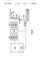
- FIG. 1is a block schematic diagram of the presently preferred embodiment of an ultrasonic position locating device for accomplishing the present inventive method
- FIG. 2is a wave form diagram representing a single ultrasonic burst as produced using the present invention
- FIG. 3is a wave form diagram showing the separation in time of bursts of ultrasonic waves, according to the present invention.
- FIG. 4is a schematic diagram of an analog signal processing section according to the present invention.
- FIG. 5is a schematic diagram of an analog sample and store section according to the present invention.
- FIG. 6is a wave form representation of a peak follower output signal as produced within the best presently known embodiment of the present invention.
- FIG. 7is a wave form representation of a half wave processed signal as produced within the best presently known embodiment of the present invention.
- FIG. 8is a wave form representation of a summed half wave signal as produced within the best presently known embodiment of the present invention.
- FIG. 9is a block schematic diagram of an equally preferred alternate embodiment of an ultrasonic position locating device according the present invention.
- FIG. 10is a schematic diagram of an analog sample and store section as used in the equally preferred alternate embodiment of the present invention.
- the best presently known mode for carrying out the inventionis a digital computer input device having ultrasonic transmitting and receiving means and means for accurately determining time of travel of an ultrasonic wave between the transmitting and receiving means. Further, the best presently known embodiment of the present invention includes calculating means for determining a position based upon the sound wave transit times between the transmitting and receiving means.
- the predominant expected usage of the inventive ultrasonic position locating methodis in the data processing industry, particularly in the data input portion of interactive computer devices wherein accurate and effortless conversion of positional information into digital-computer-usable data is desirable.
- the ultrasonic position determining device of the presently preferred embodiment of the present inventionis illustrated in a block schematic diagram in FIG. 1 and is designated therein by the general reference character 10.
- the improved ultrasonic position determining device 10does not differ significantly from conventional ultrasonic position determining devices.
- a movable marker 12 having a piezo-electric emitting transducer 14 and two momentary contact switches 16is that portion of the position determining device 10 which is moved by a user to a position to be determined.
- the two momentary switches 16constitute a conventional appurtenance commonly found on computer input devices for providing an additional means of user interaction.
- the switches 16are connected to a conventional switch sensing device 18 which, in turn, provides a signal to a computer/calculator 20 when one or both of the switches 16 are depressed.
- the switches 16 and the switch sensing device 18are not unique to the present invention and they have no direct relevance to the present inventive method. Further, the selection of the quantity of switches 16 to be included is somewhat arbitrary, and the inventive method could be practiced with any number of switches 16 or with no comparable switches.
- the emitting transducer 14emits an ultrasonic wave burst 22 (FIG. 2) when triggered by a pulse sender 24.
- the pulse senderis itself triggered by a clocking device 26 which uses conventional means to provide signals to the pulse sender 24 to cause the emitting transducer 14 to emit a wave burst 22 (FIG. 2) of the desired characteristics.
- the emitting transducer 14is chosen to be of a piezo-electric type because such devices have an inherent Q factor which prevents them from instantly attaining maximum signal amplitude.
- signal amplitudenaturally increases over several cycles, as is depicted in the representation of the wave burst 22 of FIG. 2.
- This characteristicis desirable in the application because the gradual rise in amplitude prevents an acoustic shock wave from being formed in front of each wave burst which would result in the creation of an audible signal component at the frequency of repetition of the wave bursts 22.
- the present inventive methodmakes use of the natural gradual increase in signal amplitude provided by a piezo-electric device to aid in more precisely identifying a reference point within the wave burst 22, as will be discussed hereinafter.
- the wave burst 22is a short series of individual cycles 28.
- the frequency of repetition of the cycles 28 within a wave burst 22is 22.5 KHz.
- the pulse sender 24is caused to send at this frequency because it is just outside of the normal range of human hearing. Obviously, the lower the frequency, the easier it will be to select and analyze an individual cycle 28, but a lower frequency would produce an undesirable audible sound.
- FIG. 3wherein is shown a representation of a wave burst series 29 having a sequence of wave bursts 22 with an absence of signal therebetween, it can be seen that each of the bursts 22 is separated by a dead air period 30 during which no ultrasonic wave cycles 28 are being produced.
- the wave bursts 22are generated at a repetition rate of 100 Hz. Several considerations are involved in the selection of this rate. The repetition rate must obviously not be so slow that subtle movements of the marker are lost between repetitions.
- the rateshould also be selected to sufficiently separate the wave bursts 22 in time such that echoes and reflections of a previous burst 22 will be dissipated prior to emanation of its next following burst 22, or else interference and false readings will occur.
- each wave burst 22must not be overly long in duration.
- the piezo-electric emitting transducer 14(FIG. 1) have a Q factor sufficiently large to cause the wave burst 22 to ramp up in magnitude over several cycles 28, the Q factor of the transducer 14 should also not be so large that it takes more than just a few cycles 28 for the wave burst 22 to ramp up or to ramp down. Therefore, the inventor has chosen, for the presently preferred embodiment of the invention, to use a transducer with a wider frequency bandwidth and smaller Q factor than many commercially available transducers.
- the emitting transducer 14is designed for Operation in the 18 KHz to 24 KHz range.
- the particular transducer usedis commercially available from muRata Manufacturing Company, Ltd., 2200 Lake Park Drive, Smyrna, Ga., under the part number MA23L3.
- This type deviceis particularly suitable for the application also because, as will be discussed hereinafter, it is desirable that, for purposes of practicing the present invention, there be some significant difference in magnitude between at least some successive cycles 28 within the pulse 22.
- the longer it takes the transducer 14 to ramp up to its maximum outputthe less probable it will be that there will be a recognizable difference in magnitude between successive cycles 28. Therefore, this component choice represents a compromise between the necessity that the transducer 14 should not reach its peak Output magnitude immediately upon being stimulated, but neither should it take too long to reach its peak output magnitude.
- a stationary reference frame 31having a first receiving transducer 32, a second receiving transducer 34, a third receiving transducer 36 and a fourth receiving transducer 38 is provided.
- the receiving transducers 32, 34, 36 and 38are electret microphone elements, which have a low Q factor, and thus respond in a relatively linear fashion to any signal received, within the relevant frequency range.
- the stationary receiving frameis intended to be placed on a table or other work surface (not shown), although this is not critical to the invention.
- the first, second and fourth receiving transducers 32, 38 and 34lie on a first straight line 40, and are placed 9.00 inches (22.86 cm) from each other on the receiving frame 27, while the third receiving transducer 36 is placed on a second straight line 42 drawn through the second receiving transducer 34 and perpendicular to the first straight line 40.
- the third receiving transducer 36is positioned 6.00 inches (15.24 cm) from the second receiving transducer 34.
- each wave burst 22After each wave burst 22 is emitted from the transducer 14, it is propagated through the air and is received at each of the receiving transducers 32, 34, 36 and 38. Because of propagation delay of the ultrasonic signal through air, the time at which the wave burst 22 is received at each of the receiving transducers 32, 34, 36 and 38 will vary as an inverse function of the distance of the marker 12 from each respective receiving transducer 32, 34, 36 and 38.
- Signal received at each of the receiving transducers 32, 34, 36 and 38is provided to an analog signal processing unit 44 which has a first analog signal processing section 46, a second analog signal processing section 48, a third analog signal processing section 50 and a fourth analog signal processing section 52 for processing output from the receiving transducers 32, 34, 36 and 38.
- the analog signal processing unit 44identifies a second cycle 54 (FIG. 2) in the ultrasonic wave burst 22, and then identifies a zero crossing point 56 immediately following the second pulse 54.
- a signal from the clocking device 26is sent at 1/100 second intervals, as described above, to the pulse sender 24 and is also sent to a pulse detector 58.
- This signaltriggers the pulse sender to excite the emitting transducer 14 in the movable marker 12 so as to emit an ultrasonic wave burst 22, and also triggers the pulse detector 58 to simultaneously start a first distance timer clock 60, a second distance timer clock 62, a third distance timer clock 64 and a fourth distance timer clock 66 located in a distance timer unit 68.
- the computer/calculator 20utilizes times recorded by each of the distance timer clocks 60, 62, 64 and 66 to calculate the distance of each of the receiving transducers 32, 34, 36 and 38 from the movable marker 12.
- the position of the movable marker 12 relative to the receiving transducers 32, 34, 36 and 38is then calculated using ordinary trigonometric calculations according to methods utilized in prior art ultrasonic position locating methods.
- the computer/calculator 20is itself the computer into which it is desired to input positional data using the inventive device. This is in accordance with conventional prior art methods and hardware arrangements. Alternatively, one skilled in the art will appreciate that a separate computer/calculator (not shown) could be adapted to perform the functions described herein in order to free a primary computer (not shown) for other tasks.
- the distance timer clocks 60, 62, 64 and 66operate at a frequency of 6 MHz.
- emission of a wave burst 22 from the movable marker 12may not correspond exactly in time to the signal produced by the clocking device 26 which causes the distance timer clocks 60, 62, 64 and 66 to start. Further, a portion of the times recorded by the clocks 60, 62, 64 and 66 is attributable to the time between inception of an emission of a wave burst 22 and emission of the zero crossing point 56 following the second cycle 54 of the wave burst 22. However, since these factors remain constant over time (for all practical purposes) they are easily accounted for in the calculations.
- the present inventionalso does provide a means for accurately figuring variations in speed of propagation of the wave bursts 22 through ambient air, as is required in those applications requiring greater precision.
- the first, second and fourth receiving transducers 32, 38 and 34lie on a first straight line 40, and are placed 9.00 inches (22.86 cm) from each other on the receiving frame 31.
- FIG. 4serves to illustrate the design and function of any of the analog signal processing sections.
- Power for the first receiving transducer 32 (FIG. 1)is provided at a microphone power input node 72 through a microphone power isolation resistor 74.
- a power isolation capacitor 76is provided to bypass to ground any transient or alternating current content in supplied power.
- Signalis then cleaned by a first low pass filter 78 having a first low pass filter resistor 80 and a first low pass filter capacitor 82, and by a first high pass filter 84 having a first high pass filter resistor 86 and a first high pass filter capacitor 88, all connected as shown in FIG. 4.
- first fixed gain amplifier 90a first amplifier input resistor 94, a first amplifier biasing resistor 96, a first amplifier feedback resistor 98 and a first amplifier high frequency limiting feedback capacitor 100.
- Connection and selection of component parts of the first fixed gain amplifier 90are all in accordance with ordinary operational amplifier biasing procedures, as illustrated in FIG. 4.
- Signal from the first fixed gain amplifier 90is then further cleaned by a second low pass filter 102 having a second low pass filter resistor 104 and a second low pass filter capacitor 106.
- AGCautomatic gain control
- VCRvoltage controlled resistor
- the AGC low pass filterhas an AGC low pass filter resistor 118 and an AGC low pass filter capacitor 120.
- the second amplifier 116has a second JFET op. amp. 122, a second amplifier biasing resistor 124, a second amplifier feedback resistor 126 and a second amplifier high frequency limiting feedback capacitor 128. As can be seen in the schematic of FIG. 4, while the first fixed gain amplifier 90 is biased to a ground reference 130, the second amplifier is biased from an AGC bias offset voltage input node 132.
- Inclusion of the AGC low pass filter 112improves the functioning of the AGC unit 108 by tapping off any stray high frequency noise at the VCR gate node 136 so that such noise will not be amplified by the operation of the voltage controlled resistor 114.
- AGC unit 108functions to
- the second high pass filter 138has a second high pass filter resistor 144 and a second high pass filter capacitor 146
- the third high pass filter 140has a third high pass filter resistor 148 and a third high pass filter capacitor 150, as shown in FIG. 4.
- the third amplifier 142has a third JFET op. amp. 152, a third amplifier biasing resistor 154, a third amplifier input resistor 155, a third amplifier feedback resistor 156 and a third amplifier high frequency limiting feedback capacitor 158.
- the third amplifier 142is DC biased by a voltage applied at a peak offset voltage biasing node 160, which voltage is +3VDC in the best presently known embodiment 10 of the invention.
- signal appearing at a first branching node 162is a filtered and gain controlled version of signal appearing at the signal input node 70. It should be noted that there are numerous methods known in the art for accomplishing this portion of the signal processing within the first analog signal processing section 46. The inventor's choice of using three amplification stages was predicated upon the relative signal levels present and the gain available from the first, second and third JFET op. amps. 92, 122, and 152. The first, second and third (JFET op. amps. 92, 122, and 152 are, in the best presently known embodiment 10 of the invention contained within a quad integrated circuit package type TL074, which was chosen because of its high input impedance and low noise characteristics.
- the low pass filters 78 and 102, and the high pass filters 84, 138 and 140are simple R/C type filters. Of course, more sophisticated active filters could be used to more completely clean the signal, but these would introduce a Q factor which would alter the ramp up rate of the ultrasonic wave burst 22 signal (FIG. 2) which, as may be appreciated, would be less than desirable given the inventive principles. Also, it should be noted that the low pass filters 78 and 102, and the high pass filters 84, 138 and 140 could be bunched together, rather than being distributed as shown in FIG. 4 and as described herein. The advantage of the arrangement used in the best presently preferred embodiment 10 lies in that signal loss occurring within filters can be compensated in steps at the various amplifier stages.
- sample and hold 164From the first branching node 162 signal is supplied to an analog sample and store unit (sample and hold) 164.
- sample and hold 164signal is applied to a sample and hold input node 166 and fed to a peak detector circuit 168 through a current limiting resistor 170.
- the peak detector circuit 168has a peak detector diode 172 and a peak storage capacitor 174 configured as shown in FIG. 5.
- the peak storage capacitor 174is biased with +9VDC applied at a peak detector biasing node 176.
- a peak detector output node 178will retain an instantaneous DC voltage level equal to the most negative voltage encountered in a just previously processed ultrasonic wave burst 22 (FIG. 2), which voltage will be the sum of the most negative excursion of any individual cycle 28 within that wave burst 22 plus the +3VDC supplied at the peak offset voltage biasing node 160
- a peak output signal 180 representative of signal that might be present at the peak detector output node 178is illustrated in FIG. 6 superimposed upon the individual cycles 28 of the ultrasonic wave burst 22.
- FIG. 6is not drawn to scale (nor are any of the other figures herein), a zero voltage reference 182 and a +3VDC bias reference 184 are shown to illustrate the voltage summation described herein.
- the peak output signal 180(FIG. 6) present at the peak detector output node 178 is coupled through a first high impedance unity gain buffer amplifier (first buffer amplifier) 186, a damping resistor a sample switch 190, and a second buffer amplifier 192 to a sample and hold output node 194.
- first buffer amplifierunity gain buffer amplifier
- damping resistora sample switch 190
- second buffer amplifiera second buffer amplifier 192
- a first select switch 196controls signal path to a hold capacitor 198.
- a dump switch 204provides a path to dump any charge present on the peak storage capacitor 174 through a dump level node 206 when timing signal is applied to a dump timing node 208.
- the timing of events within the sample and hold 164 during normal operation of the best presently known embodiment 10 of the inventionis as follows: After each ultrasonic wave burst 22 (FIG. 2) is processed by the first analog signal processing section 46, the output coupling switch 190 and the first select switch 196 are closed by applying timing pulse to both the sample pulse node 200 and the first select switch timing node 202, which allows the hold capacitor 198 to Charge to the level of the peak storage capacitor 174. In other terms, the hold capacitor 198 obtains the charge level of the highest peak level of that ultrasonic wave burst 22 which has just been processed.
- the output coupling switch 190is opened and the dump switch 204 is closed, allowing charge on the peak storage capacitor 174 to dump through the dump level node 206 while the hold capacitor 198 retains its charge.
- the dump switch 204is then reopened before the next ultrasonic wave burst 22 is received. This sequence is repeated after each ultrasonic wave burst 22 is processed.
- the peak storage capacitor 174will be employed in the detection and retention of the highest peak within that wave burst 22, while level present at the sample and hold output node will be that of highest peak of the last previously processed wave burst 22 (including any DC peak offset voltage, as previously disclosed).
- Timing signals to the sample pulse node 200, the first select switch timing node 202 and the dump timing node 208are, of course, supplied by the computer/calculator 20 (FIG. 1). Provision of such timing signals is entirely in accordance with prior art methods and apparatus for providing timing signals.
- the sample and hold unit 164, as described herein,is not necessary to the practice of the present invention. In fact, the inventor has successfully practiced the invention using a simple R/C sample and hold (not shown) with a timing constant sufficiently long to hold peak values between wave bursts 22 but yet short enough to dip sufficiently to accommodate situations wherein successive wave burst 22 magnitudes are decreasing in value. However, as will be discussed hereinafter, a more sophisticated sample and hold such as the sample and hold unit 164 described herein as being utilized within the best presently known embodiment 10 of the present invention is required in some applications of the invention.
- any first wave burst 22 in a sequence of wave bursts 22will not be useful for measurement purposes, since measurement is dependent upon comparison to a just previous wave burst 22, as will be described hereinafter.
- the damping resistor 188is provided to limit the amount by which charge on the hold capacitor 198 may vary between successive wave bursts 22 to prevent undue oscillation of this value.
- controlling softwareshould allow only a limited range of change in output data between successive cycles. If calculations would seem to indicate data outside of that range, the computer/calculator 20 (FIG. 1) should not update the output data until successive results within the acceptable range of change indicate that the system has again stabilized.
- signal appearing at the first branching node 162is also provided to a gain setting amplifier 210 through a fourth high pass filter 212.
- the fourth high pass filter 212has a fourth high pass filter resistor 214 and a fourth high pass filter capacitor 216.
- the gain setting amplifier 210has a gain setting JFET op. amp. 218, a gain setting amplifier input resistor 220, a gain setting amplifier biasing resistor 221, a gain setting amplifier feedback resistor 222 and a gain setting amplifier high frequency limiting feedback capacitor 224.
- the gain setting amplifier 210provides signal to a half wave extraction circuit 226 which has a half wave rectifying diode 228, a half wave storage capacitor 230, a bleed resistor 230 and a third high impedance unity gain buffer amplifier 232.
- a half wave processing circuit 226will modify an ultrasonic wave burst 22 signal shape to produce a half wave processed signal 234 as illustrated in FIG. 7.
- the half wave processed signal 234is shown in FIG. 7 superimposed upon the ultrasonic wave burst 22 signal from which it is derived.
- the half wave processed signalis then provided to a difference amplifier 236 having a difference JFET op. amp.
- the difference JFET op. amp. 238must be supplied with bipolar power which is provided at a first bipolar power input node 248 and a second bipolar power input node 250, as shown in the drawing of FIG. 4.
- a first bipolar power bypass capacitor 252 and a second bipolar power bypass capacitor 254are provided to clean power entering at the bipolar power input nodes 248 and 250.
- a cycle two detector 264provides a means for identifying the second cycle 258 (FIG. 8).
- the cycle two detectorhas a cycle two comparator 260, a cycle two first input resistor 262, a cycle two second input resistor 264 and a cycle two feedback resistor 268.
- the voltage level appearing at a cycle two comparator positive inputis obtained from the sample and hold output node 194 which level, as has been discussed previously herein, is the summation of the highest peak level obtained from a just previous ultrasonic wave burst 22 (FIG.
- cycle two comparator negative input 276Signal appearing at a cycle two comparator negative input 276 is the summed half wave signal 256 (FIG. 8).
- Selection of the second cycle 258is accomplished by providing a voltage at a pulse detect offset input node 282 which will cause the cycle two comparator 266 to trigger at a cycle two comparator trigger level 284 which is half way between a cycle one peak level 286 and a cycle two peak level 288.
- the cycle two comparator trigger level 284is the peak output signal 180 (FIG. 6) from the just previous wave burst 22.
- the cycle two comparator trigger level 284could be set to be any value between the cycle one peak level 286 and the cycle two peak level 288 but, of course, setting it as described herein provides the maximum latitude for error.
- the inventorhas found that the proper voltage to be applied at the pulse detect offset input node is +3VDC As described herein, output is provided at a second cycle detect output node 290 When the second cycle 2$8 (FIG. 8) has been encountered. It should be noted that the inventor has found that the characteristics of components used in the manufacture of the best presently known embodiment 10 of the invention are sufficiently consistent that no individual calibration or adjustment is required when producing an analog signal processing unit 44 (FIG. 1), the component values and voltage level setting described herein enabling implementation of the invention without such calibration or adjustment.
- the zero crossing point 56(FIG. 2) immediately following detection of the second cycle 258 is used as that reference point.
- a zero crossing detector 294is provided for the purpose.
- the zero crossing detector 294has a zero crossing high pass input capacitor 296, a zero crossing high pass input resistor 298, a zero crossing input resistor 300, a zero crossing comparator 302 and a zero crossing comparator feedback/hysteresis resistor 304
- the zero crossing high pass input capacitor 296eliminates any DC component from signal arriving at a zero crossing comparator positive input 306.
- a zero crossing comparator negative input 308is set to ground 130. Therefore a signal will be provided at a zero crossing detect output node 310 when an individual cycle 28 (FIG. 2) crosses ground level from negative to positive, as at the zero crossing point 56 (FIG. 2).
- signals appearing at the second cycle detect output node 290 and the zero crossing detect output node 310are conditioned by conventional means to provide TTL level inputs for the pulse detector 58 (FIG. 1).
- the pulse detector 58causes the appropriate distance timer clock 60, 62, 64 or 66 within the distance timer unit 68 to stop.
- the time at which each distance timer clock 60, 62, 64 and 66 is stoppedis a reliable indication of the distance of respective receiving transducers 32, 34, 36 and 38 from the movable marker 12.
- Calculations to determine the position of the movable marker 12then are performed by the computer/calculator according to prior art methods for determining the position of a marker based upon distance from that marker to fixed reference points. Also, as previously described herein, the best presently known embodiment 10 of the invention provides sufficient reference points to determine position in three dimensions and to correct for variances in extant speed of sound.
- the first analog signal processing section 46(which is identical to the analog signal processing sections 48, 50 and 52) is dependent in operation upon the setting of certain signal levels within the circuit. Although it is believed that one skilled in the art should be able to attain the desired results given the description of such signal levels as heretofore described along with the discussion of relevant theory which has been provided, in order to ensure enablement of the unique hardware utilized to implement the inventive method in the best presently known embodiment 10, the following TABLE A is provided which lists values and types of the components of the first analog signal processing section.
- first amplifier input resistor10K ⁇ 96 first amplifier biasing resistor: 10K ⁇
- the best presently preferred embodiment 10 of the inventionhas an analog signal processing unit 44 having four analog signal processing sections 46, 48, 50 and 52 for effectuating the inventive method of identifying a specific point on a ultrasonic wave burst 22 and thus for providing a means to implement the inventive method for calculating distance.
- FIG. 9depicts an alternate equally preferred embodiment of the invention in which is designated therein by the general reference character 910.
- the alternate preferred embodiment 910 of the inventionutilizes the same inventive method for measuring distance as does the first preferred embodiment 10. How ever, the alternate preferred embodiment 910 makes use of the high resolution available through application of the inventive method to provide positional and attitudinal data relating to six degrees of freedom.
- the additional features found in the alternate preferred embodiment 910do require attention to some considerations not addressed in the above discussion relating to the first preferred embodiment 10 of the invention.
- the alternate preferred embodiment 910accomplishes the same inventive method as does the first preferred embodiment 10 of the invention and is similar in construction thereto.
- the alternate preferred embodiment 910like the first preferred embodiment 10, has a movable marker 912, computer/calculator 920, a clocking device 926 and a stationary reference frame 931.
- the alternate embodiment 910 of the inventiondiffers from the first preferred embodiment 10 in that a first receiving transducer 932, a second receiving transducer 934 and a third receiving transducer 936 are located in the movable marker 912.
- a fourth receiving transducer 938is located within the stationary reference frame 931.
- the alternate embodiment 910also has an analog signal processing unit 944 which has therein a first analog signal processing section 946, a second analog signal processing section 948, a third analog signal processing section 950 and a fourth analog signal processing section 9$2. Also, like the first preferred embodiment 10, the alternate preferred embodiment has a pulse detector 958, a first distance timer clock 960, a second distance timer clock 962, a third distance timer clock 964, and a fourth distance timer clock 966.
- the distance timer clocks 960, 962, 964 and 966are components of a distance timer unit 968.
- a pulse distribution unit 9310is provided which is similar in function to the pulse sender 24 of the first preferred embodiment 10 except that the pulse distribution unit 9310 sends signal sequentially to a first emitting transducer 9312, a second emitting transducer 9314 and a third emitting transducer 9316.
- the first, second and third receiving transducers 932, 934 and 936are positioned at the corners of a right triangle, as is show in FIG. 9, with the first receiving transducer 932 being 2.00 inches (5.08 cm.) from the second receiving transducer 934, and the third receiving transducer 936 being 2.00 inches (5.08 cm.) from the second receiving transducer 934.
- the emitting transducers 9312, 9314 and 9316also are positioned to form a right triangle with the first emitting transducer 9312 being 6.00 inches (15.24 cm.) from the second emitting transducer 9314 and with the third emitting transducer 9316 being 9.00 inches (22.86 cm.) from the second emitting transducer 9314.
- distance measurement between each of the first, second and third receiving transducers 932, 934 and 936 and each of the emitting transducers 9310, 9312 and 9316is accomplished.
- the emitting transducers 9312, 9314 and 9316are caused to sequentially emit ultrasonic wave bursts 22 (FIG. 2).
- the first emitting transducer 9312emits a wave burst 22 and the distance from the first emitting transducer 9312 to each of the first, second, and third receiving transducers 932, 934 and 936 is determined in the same manner described herein in conjunction with the first preferred embodiment 10 of the invention.
- the same methodis used to determine distances from the second emitting transducer 9314 and the third emitting transducer 9316 to each of the first, second, and third receiving transducers 932, 934 and 936.
- the fourth receiving transducer 938is fixed in location and located on the stationary reference frame 931 near the first emitting transducer 9312.
- the fourth receiving transducer 938provides the means used by the inventor to adjust for the extant speed of sound in the alternate preferred embodiment 910 of the invention. Since the distance from the fourth receiving transducer 938 and the third emitting transducer 9316 is fixed and known, time taken for a wave burst 22 to travel between the third emitting transducer 9316 and the fourth receiving transducer 938 provides a measure of the extant speed of sound.
- the same method and identical circuitryis used to determine the distance between the fixed fourth receiving transducer 938 and the third emitting transducer 9316 which is used to determine distance between each of the first, second and third receiving transducers 932, 934 and 936 and each of the emitting transducers 9312, 9314 and 9316.
- a less sophisticated methodmight also be employed in this part of the process, since that part of the circuitry described herein which is involved with compensation for variable distance is not really required for this one measurement.
- the alternate preferred embodiment 910 of the inventionuses the same circuitry and functions in much the same manner as does the first preferred embodiment 10.
- Means to provide the additional timing signals employed in the alternate preferred embodiment 910 and means to store additional distance timing data and to manipulate such data arithmetically to calculate positionare all entirely within the knowledge of one skilled in the art.
- a modification of the sample and hold 164 (FIG. 4) utilized in conjunction with the first preferred embodiment 10will enable the operation of the alternate preferred embodiment 910.
- the analog signal processing unit 944utilizes a signal level derived from the magnitude of a just previous wave burst 22, which magnitude is dependent upon distance between the distance between that pair of the first, second and third receiving transducers 932, 934 and 936 and the emitting transducers 9312, 9314 and 9316 which is of instant concern. Therefore, a means is provided to store such information relating to wave bursts 22 emitted from each of the emitting transducers 9312, 9314 and 9316 within the analog signal processing units 944.
- a modified sample and hold unit 9164as is used in the alternate preferred embodiment 910 of the invention, is depicted in schematic form in FIG. 10.
- the modified sample and hold unit 9164is similar to that of the sample and hold 164.
- a peak detector circuit 9168, a first high impedance unity gain buffer amplifier 9186, an output coupling switch 9190, a second high impedance unity gain buffer amplifier 9192 and a dump switch 9204function as do the corresponding parts 168, 186 190, 192 and 204 in the sample and hold 164 (FIG. 4).
- the modified sample and hold 9164has a first hold capacitor 9318, a second hold capacitor 9320, a third hold capacitor 9322, a first select switch 9324, a second select switch 9326 and a third select switch 9328.
- the first hold capacitor 9318is allowed to charge to the level of just detected by the peak detector circuit 9168 which, of course, is timed to occur just after a wave burst 22 (FIG. 2) from the first emitting transducer 9132 is received.
- signal levels corresponding to wave bursts 22 from the second emitting transducer 9314 and the third emitting transducer 9316are stored on the second hold capacitor 9320 and the third holding capacitor 9322.
- charge remaining within the peak detector circuit 9168is dumped through the dump switch 9204 and, just as was described in more detail in relation to the first preferred embodiment 10 of the invention, when each wave burst 22 is being processed, the output coupling switch is closed, and the appropriate select switch 9324, 9326 or 9328 is opened such that charge level coupled through the second high impedance buffer amplifier 9192 is representative of results obtained from a just previous wave burst 22 magnitude from the corresponding emitting transducer 9312, 9314 or 9316 as seen by the receiving transducer 932, 934 or 936 to which the particular sample and hold 9164 in question is connected.
- the alternative embodiment 910 of the inventioncould be provided with switches (not shown) such as the switches 16 shown in FIG. 1 as being employed with the first preferred embodiment 10 of the invention.
- the ultrasonic position determining devices 10 and 910closely resemble prior art conventional position determining devices in many respects.
- the substantial differenceexists in the inclusion of means for identifying a particular cycle of an ultrasonic burst and then for identifying a particular point on that cycle. No significant changes of materials are envisioned nor are any special constructions required.
- Ultrasonic position locating devicesare widely used as computer data input devices. The predominant current usages are for controlling the position of a curser on a computer screen to enable user interface with software, and to provide information about relative physical locations, as for digitizing aspects of a drawing. Additionally, applications for such devices are expanding very rapidly. Contemporary efforts to improve "virtual reality" systems, wherein users interface with a computer created environment, have created an increased need for improved position locating means.
- the ultrasonic position locating devices of the present inventionmay be utilized in any application wherein conventional digital computer input position locating devises are used.
- the increased precision of the inventive device and methodwill allow the present invention to find application wherein the positional interpretation of data input has heretofore been insufficiently accurate.
- the main area of improvementis in the ability of the present inventive method and devices to accurately measure the distance between a movable marker and a plurality of stationary reference points.
- the ultrasonic position locating devices of the present inventionmay be readily constructed and are compatible with prior art conventional positional locating methods, it is expected that they will be acceptable in the industry as substitutes for the conventional positional locating data input devices. Also, it is anticipated that the increased accuracy of the inventive devices will allow application of the inventive devices to data input applications wherein conventional positional input devices have been found to be insufficiently precise for practical application. For these and other reasons, it is expected that the utility and industrial applicability of the invention will be both significant in scope and long-lasting in duration.
Landscapes
- Engineering & Computer Science (AREA)
- General Engineering & Computer Science (AREA)
- Theoretical Computer Science (AREA)
- Physics & Mathematics (AREA)
- General Physics & Mathematics (AREA)
- Human Computer Interaction (AREA)
- Radar, Positioning & Navigation (AREA)
- Remote Sensing (AREA)
- Acoustics & Sound (AREA)
- Measurement Of Velocity Or Position Using Acoustic Or Ultrasonic Waves (AREA)
Abstract
Description
Claims (33)
Priority Applications (6)
| Application Number | Priority Date | Filing Date | Title |
|---|---|---|---|
| US07/601,942US5142506A (en) | 1990-10-22 | 1990-10-22 | Ultrasonic position locating method and apparatus therefor |
| IE368691AIE62672B1 (en) | 1990-10-22 | 1991-10-21 | Ultrasonic position locating method and apparatus therefor |
| CA 2094615CA2094615A1 (en) | 1990-10-22 | 1991-10-21 | Ultrasonic position locating method and apparatus therefor |
| JP3518523AJPH06502509A (en) | 1990-10-22 | 1991-10-21 | Ultrasonic positioning method and device |
| EP19910919592EP0554346A4 (en) | 1990-10-22 | 1991-10-21 | Ultrasonic position locating method and apparatus therefor |
| PCT/US1991/007795WO1992007346A1 (en) | 1990-10-22 | 1991-10-21 | Ultrasonic position locating method and apparatus therefor |
Applications Claiming Priority (1)
| Application Number | Priority Date | Filing Date | Title |
|---|---|---|---|
| US07/601,942US5142506A (en) | 1990-10-22 | 1990-10-22 | Ultrasonic position locating method and apparatus therefor |
Publications (1)
| Publication Number | Publication Date |
|---|---|
| US5142506Atrue US5142506A (en) | 1992-08-25 |
Family
ID=24409357
Family Applications (1)
| Application Number | Title | Priority Date | Filing Date |
|---|---|---|---|
| US07/601,942Expired - LifetimeUS5142506A (en) | 1990-10-22 | 1990-10-22 | Ultrasonic position locating method and apparatus therefor |
Country Status (1)
| Country | Link |
|---|---|
| US (1) | US5142506A (en) |
Cited By (84)
| Publication number | Priority date | Publication date | Assignee | Title |
|---|---|---|---|---|
| US5323174A (en)* | 1992-12-02 | 1994-06-21 | Matthew H. Klapman | Device for determining an orientation of at least a portion of a living body |
| US5423554A (en)* | 1993-09-24 | 1995-06-13 | Metamedia Ventures, Inc. | Virtual reality game method and apparatus |
| US5446701A (en)* | 1992-08-28 | 1995-08-29 | Teem Systems, Inc. | Object locator system |
| US5473344A (en)* | 1994-01-06 | 1995-12-05 | Microsoft Corporation | 3-D cursor positioning device |
| US5517579A (en)* | 1994-02-04 | 1996-05-14 | Baron R & D Ltd. | Handwritting input apparatus for handwritting recognition using more than one sensing technique |
| US5574479A (en)* | 1994-01-07 | 1996-11-12 | Selectech, Ltd. | Optical system for determining the roll orientation of a remote unit relative to a base unit |
| US5576727A (en)* | 1993-07-16 | 1996-11-19 | Immersion Human Interface Corporation | Electromechanical human-computer interface with force feedback |
| US5623582A (en)* | 1994-07-14 | 1997-04-22 | Immersion Human Interface Corporation | Computer interface or control input device for laparoscopic surgical instrument and other elongated mechanical objects |
| US5635951A (en)* | 1992-03-27 | 1997-06-03 | Nec Corporation | Display system with image magnification capability |
| US5691959A (en)* | 1994-04-06 | 1997-11-25 | Fujitsu, Ltd. | Stylus position digitizer using acoustic waves |
| US5691898A (en)* | 1995-09-27 | 1997-11-25 | Immersion Human Interface Corp. | Safe and low cost computer peripherals with force feedback for consumer applications |
| US5694153A (en)* | 1995-07-31 | 1997-12-02 | Microsoft Corporation | Input device for providing multi-dimensional position coordinate signals to a computer |
| US5721566A (en)* | 1995-01-18 | 1998-02-24 | Immersion Human Interface Corp. | Method and apparatus for providing damping force feedback |
| US5724264A (en)* | 1993-07-16 | 1998-03-03 | Immersion Human Interface Corp. | Method and apparatus for tracking the position and orientation of a stylus and for digitizing a 3-D object |
| US5731804A (en)* | 1995-01-18 | 1998-03-24 | Immersion Human Interface Corp. | Method and apparatus for providing high bandwidth, low noise mechanical I/O for computer systems |
| US5734373A (en)* | 1993-07-16 | 1998-03-31 | Immersion Human Interface Corporation | Method and apparatus for controlling force feedback interface systems utilizing a host computer |
| US5739811A (en)* | 1993-07-16 | 1998-04-14 | Immersion Human Interface Corporation | Method and apparatus for controlling human-computer interface systems providing force feedback |
| US5767839A (en)* | 1995-01-18 | 1998-06-16 | Immersion Human Interface Corporation | Method and apparatus for providing passive force feedback to human-computer interface systems |
| US5805140A (en)* | 1993-07-16 | 1998-09-08 | Immersion Corporation | High bandwidth force feedback interface using voice coils and flexures |
| US5821920A (en)* | 1994-07-14 | 1998-10-13 | Immersion Human Interface Corporation | Control input device for interfacing an elongated flexible object with a computer system |
| US5867146A (en)* | 1996-01-17 | 1999-02-02 | Lg Electronics Inc. | Three dimensional wireless pointing device |
| US5898599A (en) | 1993-10-01 | 1999-04-27 | Massachusetts Institute Of Technology | Force reflecting haptic interface |
| US5977958A (en)* | 1997-06-30 | 1999-11-02 | Inmotion Technologies Ltd. | Method and system for digitizing handwriting |
| WO2000028348A1 (en)* | 1998-11-10 | 2000-05-18 | Electronics For Imaging, Inc. | Transmitter pen location system |
| US6067080A (en)* | 1997-02-21 | 2000-05-23 | Electronics For Imaging | Retrofittable apparatus for converting a substantially planar surface into an electronic data capture device |
| US6100877A (en)* | 1998-05-14 | 2000-08-08 | Virtual Ink, Corp. | Method for calibrating a transcription system |
| US6104387A (en)* | 1997-05-14 | 2000-08-15 | Virtual Ink Corporation | Transcription system |
| US6108271A (en)* | 1998-12-10 | 2000-08-22 | Erskine College | Remote control device for controlling electronic devices |
| US6111565A (en)* | 1998-05-14 | 2000-08-29 | Virtual Ink Corp. | Stylus for use with transcription system |
| US6124847A (en)* | 1998-05-14 | 2000-09-26 | Virtual Ink, Corp. | Collapsible detector assembly |
| US6141293A (en)* | 1997-10-30 | 2000-10-31 | Netmor Ltd. | Ultrasonic positioning and tracking system |
| US6147681A (en)* | 1998-05-14 | 2000-11-14 | Virtual Ink, Corp. | Detector for use in a transcription system |
| US6157592A (en)* | 1998-07-06 | 2000-12-05 | Resolution Displays, Inc. | Acoustic position determination method and apparatus |
| US6172354B1 (en) | 1998-01-28 | 2001-01-09 | Microsoft Corporation | Operator input device |
| US6177927B1 (en) | 1998-05-14 | 2001-01-23 | Virtual Ink Corp. | Transcription system kit |
| US6191778B1 (en) | 1998-05-14 | 2001-02-20 | Virtual Ink Corp. | Transcription system kit for forming composite images |
| US6211863B1 (en) | 1998-05-14 | 2001-04-03 | Virtual Ink. Corp. | Method and software for enabling use of transcription system as a mouse |
| US6219032B1 (en) | 1995-12-01 | 2001-04-17 | Immersion Corporation | Method for providing force feedback to a user of an interface device based on interactions of a controlled cursor with graphical elements in a graphical user interface |
| US6292177B1 (en) | 1997-03-05 | 2001-09-18 | Tidenet, Inc. | Marking device for electronic presentation board |
| US6310615B1 (en) | 1998-05-14 | 2001-10-30 | Virtual Ink Corporation | Dual mode eraser |
| US6314055B1 (en) | 1998-10-16 | 2001-11-06 | Intersense, Inc. | Range measuring system |
| US6326565B1 (en) | 1997-02-28 | 2001-12-04 | Electronics For Imaging, Inc. | Marking device for electronic presentation board |
| US20020030664A1 (en)* | 1995-11-17 | 2002-03-14 | Immersion Corporation | Force feedback interface device with force functionality button |
| US20020054026A1 (en)* | 2000-04-17 | 2002-05-09 | Bradley Stevenson | Synchronized transmission of recorded writing data with audio |
| US6392167B1 (en) | 1998-05-07 | 2002-05-21 | Ricoh Company, Ltd. | Acoustic touch position sensing system with large touch sensing surface |
| US20020176577A1 (en)* | 2001-05-25 | 2002-11-28 | Intel Corporation | Digital signature collection and authentication |
| US20030020686A1 (en)* | 2001-07-24 | 2003-01-30 | Moll Hendrik Frank | Interface for transferring signals from a hand-operated signal generator |
| US6531692B1 (en) | 1999-03-22 | 2003-03-11 | Microsoft Corporation | Optical coupling assembly for image sensing operator input device |
| US6535206B1 (en)* | 2000-02-18 | 2003-03-18 | Intel Corporation | Ultrasonic wireless pen position determination system and method |
| US6697748B1 (en) | 1995-08-07 | 2004-02-24 | Immersion Corporation | Digitizing system and rotary table for determining 3-D geometry of an object |
| US6697300B1 (en) | 2002-09-13 | 2004-02-24 | General Dynamics Advanced Information Systems, Inc. | Method and apparatus for determining the positioning of volumetric sensor array lines |
| US6717073B2 (en) | 2000-12-29 | 2004-04-06 | Intel Corporation | Wireless display systems, styli, and associated methods |
| US6805132B2 (en)* | 2002-08-06 | 2004-10-19 | Scimed Life Systems, Inc. | Performing ultrasound ranging in the presence of ultrasound interference |
| WO2003088136A3 (en)* | 2002-04-15 | 2004-10-28 | Epos Technologies Ltd | Method and system for obtaining positioning data |
| US20040222892A1 (en)* | 2003-05-06 | 2004-11-11 | University Of Pittsburgh Of The Commonwealth System Of Higher Education | Apparatus and method for postural assessment while performing cognitive tasks |
| US6850222B1 (en) | 1995-01-18 | 2005-02-01 | Immersion Corporation | Passive force feedback for computer interface devices |
| US6859819B1 (en) | 1995-12-13 | 2005-02-22 | Immersion Corporation | Force feedback enabled over a computer network |
| US20050088413A1 (en)* | 1994-01-06 | 2005-04-28 | Microsoft Corporation | System and method of adjusting display characteristics of a displayable data file using a ergonomic computer input device |
| US6940488B1 (en) | 1994-01-06 | 2005-09-06 | Microsoft Corporation | System and method of adjusting display characteristics of a displayable data file using an ergonomic computer input device |
| US6950094B2 (en) | 1998-03-30 | 2005-09-27 | Agilent Technologies, Inc | Seeing eye mouse for a computer system |
| US20050226437A1 (en)* | 2002-05-27 | 2005-10-13 | Sonicemotion Ag | Method and device for generating information relating to relative position of a set of at least three acoustic transducers (as amended) |
| US20050227719A1 (en)* | 2003-11-12 | 2005-10-13 | Research In Motion Limited | Data-capable network prioritization with reduced delays in data service |
| US7027032B2 (en) | 1995-12-01 | 2006-04-11 | Immersion Corporation | Designing force sensations for force feedback computer applications |
| US7039866B1 (en) | 1995-12-01 | 2006-05-02 | Immersion Corporation | Method and apparatus for providing dynamic force sensations for force feedback computer applications |
| US7050509B2 (en) | 1997-04-22 | 2006-05-23 | Silicon Laboratories Inc. | Digital isolation system with hybrid circuit in ADC calibration loop |
| US7091950B2 (en) | 1993-07-16 | 2006-08-15 | Immersion Corporation | Force feedback device including non-rigid coupling |
| US7113166B1 (en) | 1995-06-09 | 2006-09-26 | Immersion Corporation | Force feedback devices using fluid braking |
| US7131073B2 (en) | 1995-12-13 | 2006-10-31 | Immersion Corporation | Force feedback applications based on cursor engagement with graphical targets |
| US7158112B2 (en) | 1995-12-01 | 2007-01-02 | Immersion Corporation | Interactions between simulated objects with force feedback |
| US7209117B2 (en) | 1995-12-01 | 2007-04-24 | Immersion Corporation | Method and apparatus for streaming force values to a force feedback device |
| US20080144770A1 (en)* | 2004-12-09 | 2008-06-19 | Suk Lee | Radiation Treatment System Having a Function of Compensating Displacement According to Breathing and Method for Controlling the System |
| US20080166048A1 (en)* | 2005-03-23 | 2008-07-10 | Epos Technologies Limited Trident Chambers | Method and System for Digital Pen Assembly |
| US7411576B2 (en) | 2003-10-30 | 2008-08-12 | Sensable Technologies, Inc. | Force reflecting haptic interface |
| US20090208422A1 (en)* | 2004-09-29 | 2009-08-20 | Medical Research Fund Of Tel Aviv | Composition for improving efficiency of drug delivery |
| US20100142325A1 (en)* | 2007-03-14 | 2010-06-10 | Epos Development Ltd. | Mems microphone |
| US20100203609A1 (en)* | 2007-07-23 | 2010-08-12 | Ramot At Tel Aviv University Ltd. | Photocatalytic hydrogen production and polypeptides capable of same |
| US7852318B2 (en) | 2004-05-17 | 2010-12-14 | Epos Development Ltd. | Acoustic robust synchronization signaling for acoustic positioning system |
| US7944433B2 (en) | 1995-11-17 | 2011-05-17 | Immersion Corporation | Force feedback device including actuator with moving magnet |
| US20120209117A1 (en)* | 2006-03-08 | 2012-08-16 | Orthosensor, Inc. | Surgical Measurement Apparatus and System |
| US8508469B1 (en) | 1995-12-01 | 2013-08-13 | Immersion Corporation | Networked applications including haptic feedback |
| US8603015B2 (en) | 2004-12-13 | 2013-12-10 | Tel Hashomer Medical Research Infrastructure And Services Ltd. | Method and system for monitoring ablation of tissues |
| US20160202788A1 (en)* | 2015-01-13 | 2016-07-14 | Sony Corporation | Multi-on-body action detection based on ultrasound |
| WO2018095804A1 (en) | 2016-11-25 | 2018-05-31 | Sensoryx AG | Wearable motion tracking system |
| US10945706B2 (en) | 2017-05-05 | 2021-03-16 | Biim Ultrasound As | Hand held ultrasound probe |
Citations (11)
| Publication number | Priority date | Publication date | Assignee | Title |
|---|---|---|---|---|
| US3134099A (en)* | 1962-12-21 | 1964-05-19 | Ibm | Ultrasonic data converter |
| US3626483A (en)* | 1969-07-16 | 1971-12-07 | Science Accessories Corp | Spark pen |
| US4012588A (en)* | 1975-08-29 | 1977-03-15 | Science Accessories Corporation | Position determining apparatus and transducer therefor |
| US4124838A (en)* | 1976-12-29 | 1978-11-07 | Science Accessories Corporation | Apparatus for position determination |
| US4357672A (en)* | 1980-07-30 | 1982-11-02 | Science Accessories Corporation | Distance ranging apparatus and method |
| US4891474A (en)* | 1989-02-23 | 1990-01-02 | Science Accessories Corp. | Sparking stylus for acoustic digitizer |
| US4933915A (en)* | 1986-09-16 | 1990-06-12 | Bostroem Jan I | Method of indicating the time of an acoustic pulse and a device for carrying out the method |
| US4956824A (en)* | 1989-09-12 | 1990-09-11 | Science Accessories Corp. | Position determination apparatus |
| US4991148A (en)* | 1989-09-26 | 1991-02-05 | Gilchrist Ian R | Acoustic digitizing system |
| US5009277A (en)* | 1990-03-19 | 1991-04-23 | Science Accessories Corp. | Method and apparatus for position determination |
| US5043950A (en)* | 1990-01-19 | 1991-08-27 | Science Accessories Corp. | Apparatus and method for distance determination |
- 1990
- 1990-10-22USUS07/601,942patent/US5142506A/ennot_activeExpired - Lifetime
Patent Citations (11)
| Publication number | Priority date | Publication date | Assignee | Title |
|---|---|---|---|---|
| US3134099A (en)* | 1962-12-21 | 1964-05-19 | Ibm | Ultrasonic data converter |
| US3626483A (en)* | 1969-07-16 | 1971-12-07 | Science Accessories Corp | Spark pen |
| US4012588A (en)* | 1975-08-29 | 1977-03-15 | Science Accessories Corporation | Position determining apparatus and transducer therefor |
| US4124838A (en)* | 1976-12-29 | 1978-11-07 | Science Accessories Corporation | Apparatus for position determination |
| US4357672A (en)* | 1980-07-30 | 1982-11-02 | Science Accessories Corporation | Distance ranging apparatus and method |
| US4933915A (en)* | 1986-09-16 | 1990-06-12 | Bostroem Jan I | Method of indicating the time of an acoustic pulse and a device for carrying out the method |
| US4891474A (en)* | 1989-02-23 | 1990-01-02 | Science Accessories Corp. | Sparking stylus for acoustic digitizer |
| US4956824A (en)* | 1989-09-12 | 1990-09-11 | Science Accessories Corp. | Position determination apparatus |
| US4991148A (en)* | 1989-09-26 | 1991-02-05 | Gilchrist Ian R | Acoustic digitizing system |
| US5043950A (en)* | 1990-01-19 | 1991-08-27 | Science Accessories Corp. | Apparatus and method for distance determination |
| US5009277A (en)* | 1990-03-19 | 1991-04-23 | Science Accessories Corp. | Method and apparatus for position determination |
Cited By (157)
| Publication number | Priority date | Publication date | Assignee | Title |
|---|---|---|---|---|
| US5635951A (en)* | 1992-03-27 | 1997-06-03 | Nec Corporation | Display system with image magnification capability |
| US5446701A (en)* | 1992-08-28 | 1995-08-29 | Teem Systems, Inc. | Object locator system |
| US5353042A (en)* | 1992-12-02 | 1994-10-04 | Klapman Matthew H | Method for determining an orientation of an object |
| US5323174A (en)* | 1992-12-02 | 1994-06-21 | Matthew H. Klapman | Device for determining an orientation of at least a portion of a living body |
| US5739811A (en)* | 1993-07-16 | 1998-04-14 | Immersion Human Interface Corporation | Method and apparatus for controlling human-computer interface systems providing force feedback |
| US6046727A (en)* | 1993-07-16 | 2000-04-04 | Immersion Corporation | Three dimensional position sensing interface with force output |
| US6987504B2 (en) | 1993-07-16 | 2006-01-17 | Immersion Corporation | Interface device for sensing position and orientation and outputting force to a user |
| US5576727A (en)* | 1993-07-16 | 1996-11-19 | Immersion Human Interface Corporation | Electromechanical human-computer interface with force feedback |
| US7061467B2 (en) | 1993-07-16 | 2006-06-13 | Immersion Corporation | Force feedback device with microprocessor receiving low level commands |
| US7091950B2 (en) | 1993-07-16 | 2006-08-15 | Immersion Corporation | Force feedback device including non-rigid coupling |
| US7605800B2 (en) | 1993-07-16 | 2009-10-20 | Immersion Corporation | Method and apparatus for controlling human-computer interface systems providing force feedback |
| US5929846A (en)* | 1993-07-16 | 1999-07-27 | Immersion Corporation | Force feedback interface device including grounded sensor system |
| US5880714A (en)* | 1993-07-16 | 1999-03-09 | Immersion Corporation | Three-dimensional cursor control interface with force feedback |
| US5701140A (en)* | 1993-07-16 | 1997-12-23 | Immersion Human Interface Corp. | Method and apparatus for providing a cursor control interface with force feedback |
| US5805140A (en)* | 1993-07-16 | 1998-09-08 | Immersion Corporation | High bandwidth force feedback interface using voice coils and flexures |
| US5724264A (en)* | 1993-07-16 | 1998-03-03 | Immersion Human Interface Corp. | Method and apparatus for tracking the position and orientation of a stylus and for digitizing a 3-D object |
| US6125337A (en)* | 1993-07-16 | 2000-09-26 | Microscribe, Llc | Probe apparatus and method for tracking the position and orientation of a stylus and controlling a cursor |
| US5734373A (en)* | 1993-07-16 | 1998-03-31 | Immersion Human Interface Corporation | Method and apparatus for controlling force feedback interface systems utilizing a host computer |
| US5423554A (en)* | 1993-09-24 | 1995-06-13 | Metamedia Ventures, Inc. | Virtual reality game method and apparatus |
| US6853965B2 (en) | 1993-10-01 | 2005-02-08 | Massachusetts Institute Of Technology | Force reflecting haptic interface |
| US6405158B1 (en) | 1993-10-01 | 2002-06-11 | Massachusetts Institute Of Technology | Force reflecting haptic inteface |
| US5898599A (en) | 1993-10-01 | 1999-04-27 | Massachusetts Institute Of Technology | Force reflecting haptic interface |
| US7480600B2 (en) | 1993-10-01 | 2009-01-20 | The Massachusetts Institute Of Technology | Force reflecting haptic interface |
| US6940488B1 (en) | 1994-01-06 | 2005-09-06 | Microsoft Corporation | System and method of adjusting display characteristics of a displayable data file using an ergonomic computer input device |
| US7322011B2 (en) | 1994-01-06 | 2008-01-22 | Microsoft Corporation | System and method of adjusting display characteristics of a displayable data file using an ergonomic computer input device |
| US20050088413A1 (en)* | 1994-01-06 | 2005-04-28 | Microsoft Corporation | System and method of adjusting display characteristics of a displayable data file using a ergonomic computer input device |
| US5473344A (en)* | 1994-01-06 | 1995-12-05 | Microsoft Corporation | 3-D cursor positioning device |
| US5963197A (en)* | 1994-01-06 | 1999-10-05 | Microsoft Corporation | 3-D cursor positioning device |
| US5574479A (en)* | 1994-01-07 | 1996-11-12 | Selectech, Ltd. | Optical system for determining the roll orientation of a remote unit relative to a base unit |
| US5517579A (en)* | 1994-02-04 | 1996-05-14 | Baron R & D Ltd. | Handwritting input apparatus for handwritting recognition using more than one sensing technique |
| US5691959A (en)* | 1994-04-06 | 1997-11-25 | Fujitsu, Ltd. | Stylus position digitizer using acoustic waves |
| US6323837B1 (en) | 1994-07-14 | 2001-11-27 | Immersion Corporation | Method and apparatus for interfacing an elongated object with a computer system |
| US7215326B2 (en) | 1994-07-14 | 2007-05-08 | Immersion Corporation | Physically realistic computer simulation of medical procedures |
| US6037927A (en)* | 1994-07-14 | 2000-03-14 | Immersion Corporation | Method and apparatus for providing force feedback to the user of an interactive computer simulation |
| US8184094B2 (en) | 1994-07-14 | 2012-05-22 | Immersion Corporation | Physically realistic computer simulation of medical procedures |
| US5623582A (en)* | 1994-07-14 | 1997-04-22 | Immersion Human Interface Corporation | Computer interface or control input device for laparoscopic surgical instrument and other elongated mechanical objects |
| US6654000B2 (en) | 1994-07-14 | 2003-11-25 | Immersion Corporation | Physically realistic computer simulation of medical procedures |
| US5821920A (en)* | 1994-07-14 | 1998-10-13 | Immersion Human Interface Corporation | Control input device for interfacing an elongated flexible object with a computer system |
| US7023423B2 (en) | 1995-01-18 | 2006-04-04 | Immersion Corporation | Laparoscopic simulation interface |
| US6271828B1 (en) | 1995-01-18 | 2001-08-07 | Immersion Corporation | Force feedback interface devices providing resistance forces using a fluid |
| US7821496B2 (en) | 1995-01-18 | 2010-10-26 | Immersion Corporation | Computer interface apparatus including linkage having flex |
| US6154198A (en)* | 1995-01-18 | 2000-11-28 | Immersion Corporation | Force feedback interface apparatus including backlash and for generating feel sensations |
| US5767839A (en)* | 1995-01-18 | 1998-06-16 | Immersion Human Interface Corporation | Method and apparatus for providing passive force feedback to human-computer interface systems |
| US6850222B1 (en) | 1995-01-18 | 2005-02-01 | Immersion Corporation | Passive force feedback for computer interface devices |
| US5731804A (en)* | 1995-01-18 | 1998-03-24 | Immersion Human Interface Corp. | Method and apparatus for providing high bandwidth, low noise mechanical I/O for computer systems |
| US5721566A (en)* | 1995-01-18 | 1998-02-24 | Immersion Human Interface Corp. | Method and apparatus for providing damping force feedback |
| US7113166B1 (en) | 1995-06-09 | 2006-09-26 | Immersion Corporation | Force feedback devices using fluid braking |
| US6486872B2 (en) | 1995-06-09 | 2002-11-26 | Immersion Corporation | Method and apparatus for providing passive fluid force feedback |
| US5694153A (en)* | 1995-07-31 | 1997-12-02 | Microsoft Corporation | Input device for providing multi-dimensional position coordinate signals to a computer |
| US6134506A (en)* | 1995-08-07 | 2000-10-17 | Microscribe Llc | Method and apparatus for tracking the position and orientation of a stylus and for digitizing a 3-D object |
| US6078876A (en)* | 1995-08-07 | 2000-06-20 | Microscribe, Llc | Method and apparatus for tracking the position and orientation of a stylus and for digitizing a 3-D object |
| US7054775B2 (en) | 1995-08-07 | 2006-05-30 | Immersion Corporation | Digitizing system and rotary table for determining 3-D geometry of an object |
| US6697748B1 (en) | 1995-08-07 | 2004-02-24 | Immersion Corporation | Digitizing system and rotary table for determining 3-D geometry of an object |
| US7038657B2 (en) | 1995-09-27 | 2006-05-02 | Immersion Corporation | Power management for interface devices applying forces |
| US5691898A (en)* | 1995-09-27 | 1997-11-25 | Immersion Human Interface Corp. | Safe and low cost computer peripherals with force feedback for consumer applications |
| US7800585B2 (en) | 1995-10-06 | 2010-09-21 | Avago Technologies Ecbu Ip (Singapore) Pte. Ltd. | Method of operating an optical mouse |
| US7808485B2 (en) | 1995-10-06 | 2010-10-05 | Avago Technologies Ecbu Ip (Singapore) Pte. Ltd. | Method of operating an optical mouse |
| US20080048983A1 (en)* | 1995-10-06 | 2008-02-28 | Gordon Gary B | Method of operating an optical mouse |
| US20050231484A1 (en)* | 1995-10-06 | 2005-10-20 | Agilent Technologies, Inc. | Optical mouse with uniform level detection method |
| US7907120B2 (en) | 1995-10-06 | 2011-03-15 | Avago Technologies Ecbu Ip (Singapore) Pte. Ltd. | Optical mouse with uniform level detection method |
| US7791590B1 (en) | 1995-10-06 | 2010-09-07 | Avago Technologies Ecbu Ip (Singapore) Pte. Ltd. | Optical mouse with uniform level detection |
| US20080055243A1 (en)* | 1995-10-06 | 2008-03-06 | Gordon Gary B | Method of operating an optical mouse |
| US8350812B2 (en) | 1995-10-06 | 2013-01-08 | Pixart Imaging Inc. | Method and arrangement for tracking movement relative to a surface |
| US20070103439A1 (en)* | 1995-10-06 | 2007-05-10 | Avago Technologies, Ltd. | Method of operating an optical mouse |
| US20110141022A1 (en)* | 1995-10-06 | 2011-06-16 | Avago Technologies Ecbu Ip (Singapore) Pte. Ltd. | Method and arrangement for tracking movement relative to a surface |
| US8212778B2 (en) | 1995-10-06 | 2012-07-03 | Avago Technologies Ecbu Ip (Singapore) Pte. Ltd. | Imaging and navigation arrangement for controlling a cursor |
| US20020030664A1 (en)* | 1995-11-17 | 2002-03-14 | Immersion Corporation | Force feedback interface device with force functionality button |
| US7944433B2 (en) | 1995-11-17 | 2011-05-17 | Immersion Corporation | Force feedback device including actuator with moving magnet |
| US8508469B1 (en) | 1995-12-01 | 2013-08-13 | Immersion Corporation | Networked applications including haptic feedback |
| US7209117B2 (en) | 1995-12-01 | 2007-04-24 | Immersion Corporation | Method and apparatus for streaming force values to a force feedback device |
| US6219032B1 (en) | 1995-12-01 | 2001-04-17 | Immersion Corporation | Method for providing force feedback to a user of an interface device based on interactions of a controlled cursor with graphical elements in a graphical user interface |
| US8072422B2 (en) | 1995-12-01 | 2011-12-06 | Immersion Corporation | Networked applications including haptic feedback |
| US7199790B2 (en) | 1995-12-01 | 2007-04-03 | Immersion Corporation | Providing force feedback to a user of an interface device based on interactions of a user-controlled cursor in a graphical user interface |
| US7027032B2 (en) | 1995-12-01 | 2006-04-11 | Immersion Corporation | Designing force sensations for force feedback computer applications |
| US7636080B2 (en) | 1995-12-01 | 2009-12-22 | Immersion Corporation | Networked applications including haptic feedback |
| US7158112B2 (en) | 1995-12-01 | 2007-01-02 | Immersion Corporation | Interactions between simulated objects with force feedback |
| US7039866B1 (en) | 1995-12-01 | 2006-05-02 | Immersion Corporation | Method and apparatus for providing dynamic force sensations for force feedback computer applications |
| US6859819B1 (en) | 1995-12-13 | 2005-02-22 | Immersion Corporation | Force feedback enabled over a computer network |
| US7131073B2 (en) | 1995-12-13 | 2006-10-31 | Immersion Corporation | Force feedback applications based on cursor engagement with graphical targets |
| US5867146A (en)* | 1996-01-17 | 1999-02-02 | Lg Electronics Inc. | Three dimensional wireless pointing device |
| US6067080A (en)* | 1997-02-21 | 2000-05-23 | Electronics For Imaging | Retrofittable apparatus for converting a substantially planar surface into an electronic data capture device |
| US6326565B1 (en) | 1997-02-28 | 2001-12-04 | Electronics For Imaging, Inc. | Marking device for electronic presentation board |
| US6292177B1 (en) | 1997-03-05 | 2001-09-18 | Tidenet, Inc. | Marking device for electronic presentation board |
| US7050509B2 (en) | 1997-04-22 | 2006-05-23 | Silicon Laboratories Inc. | Digital isolation system with hybrid circuit in ADC calibration loop |
| US6104387A (en)* | 1997-05-14 | 2000-08-15 | Virtual Ink Corporation | Transcription system |
| US5977958A (en)* | 1997-06-30 | 1999-11-02 | Inmotion Technologies Ltd. | Method and system for digitizing handwriting |
| US6141293A (en)* | 1997-10-30 | 2000-10-31 | Netmor Ltd. | Ultrasonic positioning and tracking system |
| US6172354B1 (en) | 1998-01-28 | 2001-01-09 | Microsoft Corporation | Operator input device |
| US6950094B2 (en) | 1998-03-30 | 2005-09-27 | Agilent Technologies, Inc | Seeing eye mouse for a computer system |
| US6392167B1 (en) | 1998-05-07 | 2002-05-21 | Ricoh Company, Ltd. | Acoustic touch position sensing system with large touch sensing surface |
| US6191778B1 (en) | 1998-05-14 | 2001-02-20 | Virtual Ink Corp. | Transcription system kit for forming composite images |
| US6111565A (en)* | 1998-05-14 | 2000-08-29 | Virtual Ink Corp. | Stylus for use with transcription system |
| US6147681A (en)* | 1998-05-14 | 2000-11-14 | Virtual Ink, Corp. | Detector for use in a transcription system |
| US6100877A (en)* | 1998-05-14 | 2000-08-08 | Virtual Ink, Corp. | Method for calibrating a transcription system |
| US6310615B1 (en) | 1998-05-14 | 2001-10-30 | Virtual Ink Corporation | Dual mode eraser |
| US6124847A (en)* | 1998-05-14 | 2000-09-26 | Virtual Ink, Corp. | Collapsible detector assembly |
| US6177927B1 (en) | 1998-05-14 | 2001-01-23 | Virtual Ink Corp. | Transcription system kit |
| US6211863B1 (en) | 1998-05-14 | 2001-04-03 | Virtual Ink. Corp. | Method and software for enabling use of transcription system as a mouse |
| US6157592A (en)* | 1998-07-06 | 2000-12-05 | Resolution Displays, Inc. | Acoustic position determination method and apparatus |
| US6314055B1 (en) | 1998-10-16 | 2001-11-06 | Intersense, Inc. | Range measuring system |
| US6414673B1 (en) | 1998-11-10 | 2002-07-02 | Tidenet, Inc. | Transmitter pen location system |
| WO2000028348A1 (en)* | 1998-11-10 | 2000-05-18 | Electronics For Imaging, Inc. | Transmitter pen location system |
| US6108271A (en)* | 1998-12-10 | 2000-08-22 | Erskine College | Remote control device for controlling electronic devices |
| US6531692B1 (en) | 1999-03-22 | 2003-03-11 | Microsoft Corporation | Optical coupling assembly for image sensing operator input device |
| US6535206B1 (en)* | 2000-02-18 | 2003-03-18 | Intel Corporation | Ultrasonic wireless pen position determination system and method |
| US20020054026A1 (en)* | 2000-04-17 | 2002-05-09 | Bradley Stevenson | Synchronized transmission of recorded writing data with audio |
| US7248251B2 (en) | 2000-12-29 | 2007-07-24 | Intel Corporation | Wireless display systems and stylii |
| US6717073B2 (en) | 2000-12-29 | 2004-04-06 | Intel Corporation | Wireless display systems, styli, and associated methods |
| US20040169644A1 (en)* | 2000-12-29 | 2004-09-02 | Intel Corporation | Wireless display systems and stylii |
| US7279646B2 (en) | 2001-05-25 | 2007-10-09 | Intel Corporation | Digital signature collection and authentication |
| US8537141B2 (en) | 2001-05-25 | 2013-09-17 | Intel Corporation | Digital signature collection and authentication |
| US20110090182A1 (en)* | 2001-05-25 | 2011-04-21 | Jianping Xu | Digital signature collection and authentication |
| US20020176577A1 (en)* | 2001-05-25 | 2002-11-28 | Intel Corporation | Digital signature collection and authentication |
| US8970561B2 (en) | 2001-05-25 | 2015-03-03 | Intel Corporation | Digital signature collection and authentication |
| US8547363B2 (en) | 2001-05-25 | 2013-10-01 | Intel Corporation | Digital signature collection and authentication |
| US6950090B2 (en)* | 2001-07-24 | 2005-09-27 | Koninklijke Philips Electronics N.V. | Interface for transferring signals from a hand-operated signal generator |
| US20030020686A1 (en)* | 2001-07-24 | 2003-01-30 | Moll Hendrik Frank | Interface for transferring signals from a hand-operated signal generator |
| US8546706B2 (en) | 2002-04-15 | 2013-10-01 | Qualcomm Incorporated | Method and system for obtaining positioning data |
| US9195325B2 (en) | 2002-04-15 | 2015-11-24 | Qualcomm Incorporated | Method and system for obtaining positioning data |
| WO2003088136A3 (en)* | 2002-04-15 | 2004-10-28 | Epos Technologies Ltd | Method and system for obtaining positioning data |
| US9446520B2 (en) | 2002-04-15 | 2016-09-20 | Qualcomm Incorporated | Method and system for robotic positioning |
| US7272073B2 (en)* | 2002-05-27 | 2007-09-18 | Sonicemotion Ag | Method and device for generating information relating to the relative position of a set of at least three acoustic transducers |
| US20050226437A1 (en)* | 2002-05-27 | 2005-10-13 | Sonicemotion Ag | Method and device for generating information relating to relative position of a set of at least three acoustic transducers (as amended) |
| US6805132B2 (en)* | 2002-08-06 | 2004-10-19 | Scimed Life Systems, Inc. | Performing ultrasound ranging in the presence of ultrasound interference |
| US20050038341A1 (en)* | 2002-08-06 | 2005-02-17 | Scimed Life Systems, Inc. | Performing ultrasound ranging in the presence of ultrasound interference |
| US7374537B2 (en) | 2002-08-06 | 2008-05-20 | Boston Scientific Scimed, Inc. | Performing ultrasound ranging in the presence of ultrasound interference |
| US6697300B1 (en) | 2002-09-13 | 2004-02-24 | General Dynamics Advanced Information Systems, Inc. | Method and apparatus for determining the positioning of volumetric sensor array lines |
| US20040222892A1 (en)* | 2003-05-06 | 2004-11-11 | University Of Pittsburgh Of The Commonwealth System Of Higher Education | Apparatus and method for postural assessment while performing cognitive tasks |
| US7109872B2 (en) | 2003-05-06 | 2006-09-19 | University Of Pittsburgh - Of The Commonwealth System Of Higher Education | Apparatus and method for postural assessment while performing cognitive tasks |
| US7411576B2 (en) | 2003-10-30 | 2008-08-12 | Sensable Technologies, Inc. | Force reflecting haptic interface |
| US8994643B2 (en) | 2003-10-30 | 2015-03-31 | 3D Systems, Inc. | Force reflecting haptic interface |
| US20050227719A1 (en)* | 2003-11-12 | 2005-10-13 | Research In Motion Limited | Data-capable network prioritization with reduced delays in data service |
| US7398089B2 (en) | 2003-11-12 | 2008-07-08 | Research In Motion Ltd | Data-capable network prioritization with reduced delays in data service |
| USRE43523E1 (en) | 2003-11-12 | 2012-07-17 | Research In Motion Limited | Data-capable network prioritization with reduced delays in data service |
| US7852318B2 (en) | 2004-05-17 | 2010-12-14 | Epos Development Ltd. | Acoustic robust synchronization signaling for acoustic positioning system |
| US20110098554A1 (en)* | 2004-09-29 | 2011-04-28 | Tel Hashomer Medical Research Infrastructure And Services Ltd. | Monitoring of convection enhanced drug delivery |
| US8391959B2 (en) | 2004-09-29 | 2013-03-05 | Tel Hashomer Medical Research Infrastructure And Services Ltd. | Composition for improving efficiency of drug delivery |
| US20090208422A1 (en)* | 2004-09-29 | 2009-08-20 | Medical Research Fund Of Tel Aviv | Composition for improving efficiency of drug delivery |
| US20080144770A1 (en)* | 2004-12-09 | 2008-06-19 | Suk Lee | Radiation Treatment System Having a Function of Compensating Displacement According to Breathing and Method for Controlling the System |
| US8603015B2 (en) | 2004-12-13 | 2013-12-10 | Tel Hashomer Medical Research Infrastructure And Services Ltd. | Method and system for monitoring ablation of tissues |
| US9632627B2 (en) | 2005-03-23 | 2017-04-25 | Qualcomm Incorporated | Method and system for digital pen assembly |
| US8248389B2 (en) | 2005-03-23 | 2012-08-21 | Epos Development Ltd. | Method and system for digital pen assembly |
| US20080166048A1 (en)* | 2005-03-23 | 2008-07-10 | Epos Technologies Limited Trident Chambers | Method and System for Digital Pen Assembly |
| US20110096044A1 (en)* | 2005-03-23 | 2011-04-28 | Epos Development Ltd. | Method and system for digital pen assembly |
| US8963890B2 (en) | 2005-03-23 | 2015-02-24 | Qualcomm Incorporated | Method and system for digital pen assembly |
| US20110096043A1 (en)* | 2005-03-23 | 2011-04-28 | Epos Development Ltd. | Method and system for digital pen assembly |
| US20110096042A1 (en)* | 2005-03-23 | 2011-04-28 | Epos Development Ltd. | Method and system for digital pen assembly |
| US20120209117A1 (en)* | 2006-03-08 | 2012-08-16 | Orthosensor, Inc. | Surgical Measurement Apparatus and System |
| US20100142325A1 (en)* | 2007-03-14 | 2010-06-10 | Epos Development Ltd. | Mems microphone |
| US8861312B2 (en) | 2007-03-14 | 2014-10-14 | Qualcomm Incorporated | MEMS microphone |
| US9181555B2 (en) | 2007-07-23 | 2015-11-10 | Ramot At Tel-Aviv University Ltd. | Photocatalytic hydrogen production and polypeptides capable of same |
| US20100203609A1 (en)* | 2007-07-23 | 2010-08-12 | Ramot At Tel Aviv University Ltd. | Photocatalytic hydrogen production and polypeptides capable of same |
| US20160202788A1 (en)* | 2015-01-13 | 2016-07-14 | Sony Corporation | Multi-on-body action detection based on ultrasound |
| WO2018095804A1 (en) | 2016-11-25 | 2018-05-31 | Sensoryx AG | Wearable motion tracking system |
| US10768691B2 (en) | 2016-11-25 | 2020-09-08 | Sensoryx AG | Wearable motion tracking system |
| US10945706B2 (en) | 2017-05-05 | 2021-03-16 | Biim Ultrasound As | Hand held ultrasound probe |
| US11744551B2 (en) | 2017-05-05 | 2023-09-05 | Biim Ultrasound As | Hand held ultrasound probe |
Similar Documents
| Publication | Publication Date | Title |
|---|---|---|
| US5142506A (en) | Ultrasonic position locating method and apparatus therefor | |
| US6335723B1 (en) | Transmitter pen location system | |
| EP0554346A4 (en) | Ultrasonic position locating method and apparatus therefor | |
| EP0491132B1 (en) | Coordinate input apparatus | |
| US6414673B1 (en) | Transmitter pen location system | |
| US4515021A (en) | Intervalometer time measurement apparatus and method | |
| US4317005A (en) | Position-determining system | |
| US2009459A (en) | Distance and depth finding | |
| KR20050014051A (en) | Distance Measuring Method and Device by Frequency Separation with Ultrasonic | |
| US3437834A (en) | Circuit for detecting time of occurrence of signals having an amplitude which exceeds a predetermined level | |
| JPH0618490A (en) | Method and device for searching acoustic emission source in material | |
| JPS5523476A (en) | Detection circuit device for ultrasonic propagation time | |
| CN109357610B (en) | STM 32-based multifunctional magnetostrictive displacement measuring instrument and measuring method | |
| US4006625A (en) | Amplitude sorting of oscillatory burst signals by sampling | |
| US6614719B1 (en) | Ultrasonic doppler effect speed measurement | |
| GB2318232A (en) | Adaptive threshold circuit | |
| US3805224A (en) | Method and apparatus for monitoring biological activity | |
| RU2723058C1 (en) | Method and device for compensation of heterogeneity of connection at ultrasonic test | |
| JPH048756B2 (en) | ||
| US4039747A (en) | Apparatus for converting the position of a manually operated instrument into an electrical signal | |
| EP0368351A2 (en) | Coordinate input apparatus | |
| SU1716422A1 (en) | Device for selection of acoustic signals | |
| SU478242A1 (en) | Digital Speed Meter and Ultrasound Absorption Rate | |
| RU2024942C1 (en) | Graphic information read-out device | |
| GB2250093A (en) | Ultrasonic position measuring system |
Legal Events
| Date | Code | Title | Description |
|---|---|---|---|
| AS | Assignment | Owner name:LOGITECH INC. A CORP. OF CALIFORNIA, CALIFORNIA Free format text:ASSIGNMENT OF ASSIGNORS INTEREST.;ASSIGNOR:EDEDA CONSULTING COMPANY A CORP. OF MARYLAND;REEL/FRAME:005826/0537 Effective date:19910813 Owner name:EDEDA CONSULTING COMPANY A CORP. OF MARYLAND, MA Free format text:ASSIGNMENT OF ASSIGNORS INTEREST.;ASSIGNOR:EDWARDS, BRUCE H.;REEL/FRAME:005826/0540 Effective date:19910115 | |
| STCF | Information on status: patent grant | Free format text:PATENTED CASE | |
| FPAY | Fee payment | Year of fee payment:4 | |
| FEPP | Fee payment procedure | Free format text:PAYOR NUMBER ASSIGNED (ORIGINAL EVENT CODE: ASPN); ENTITY STATUS OF PATENT OWNER: LARGE ENTITY | |
| FEPP | Fee payment procedure | Free format text:PAT HLDR NO LONGER CLAIMS SMALL ENT STAT AS INDIV INVENTOR (ORIGINAL EVENT CODE: LSM1); ENTITY STATUS OF PATENT OWNER: LARGE ENTITY | |
| FPAY | Fee payment | Year of fee payment:8 | |
| FEPP | Fee payment procedure | Free format text:PAYER NUMBER DE-ASSIGNED (ORIGINAL EVENT CODE: RMPN); ENTITY STATUS OF PATENT OWNER: LARGE ENTITY Free format text:PAYOR NUMBER ASSIGNED (ORIGINAL EVENT CODE: ASPN); ENTITY STATUS OF PATENT OWNER: LARGE ENTITY | |
| FPAY | Fee payment | Year of fee payment:12 |