US5140470A - Optical mounting apparatus - Google Patents
Optical mounting apparatusDownload PDFInfo
- Publication number
- US5140470A US5140470AUS07/638,886US63888691AUS5140470AUS 5140470 AUS5140470 AUS 5140470AUS 63888691 AUS63888691 AUS 63888691AUS 5140470 AUS5140470 AUS 5140470A
- Authority
- US
- United States
- Prior art keywords
- casing
- base plate
- lever arm
- rod
- shoulder
- Prior art date
- Legal status (The legal status is an assumption and is not a legal conclusion. Google has not performed a legal analysis and makes no representation as to the accuracy of the status listed.)
- Expired - Lifetime
Links
Images


Classifications
- G—PHYSICS
- G02—OPTICS
- G02B—OPTICAL ELEMENTS, SYSTEMS OR APPARATUS
- G02B7/00—Mountings, adjusting means, or light-tight connections, for optical elements
- G02B7/003—Alignment of optical elements
- G02B7/004—Manual alignment, e.g. micromanipulators
- G—PHYSICS
- G02—OPTICS
- G02B—OPTICAL ELEMENTS, SYSTEMS OR APPARATUS
- G02B7/00—Mountings, adjusting means, or light-tight connections, for optical elements
- G02B7/18—Mountings, adjusting means, or light-tight connections, for optical elements for prisms; for mirrors
- G02B7/182—Mountings, adjusting means, or light-tight connections, for optical elements for prisms; for mirrors for mirrors
- G02B7/1822—Mountings, adjusting means, or light-tight connections, for optical elements for prisms; for mirrors for mirrors comprising means for aligning the optical axis
- G02B7/1824—Manual alignment
- G02B7/1825—Manual alignment made by screws, e.g. for laser mirrors
Definitions
- the present inventionrelates generally to an apparatus for adjustably mounting optical elements, such as mirrors, beam splitters, lenses, gratings, and the like. More particularly, the present invention relates to an optical mount which permits adjustment of the height, rotational angle, and axial position of the optical element.
- adjustable mounting apparatusfor supporting optical components, such as mirrors, beam splitters, lenses, gratings, and the like.
- Common optical mounting apparatuscomprise pair of generally parallel plates, of which one of the plates is fixed to a surface or base and the other plate is adjustably suspended from the first plate.
- the second platemay be mounted using a "three-point suspension,” where adjustment of the perpendicular distance between the plates at each of the three suspension points can provide for axial and rotational adjustment of the second plate.
- FIGS. 1 and 2An exemplary conventional optical mounting apparatus is illustrated in FIGS. 1 and 2.
- Such conventional apparatusincludes a base plate 10 and a stage plate 12, where the plates are held together by a plurality of springs 14 (one of which is illustrated).
- Three adjustments screws 16, 18, and 20are threadably received through the base plate 10 and engage the rear surface (i.e. the surface disposed toward the base plate) of the stage plate 12. In this way, the desired "three-point suspension" mechanism is provided.
- An aperture 22is provided in the stage plate 12 in order to support the desired optical element.
- a similar aperture 24is provided in the base plate 10 so that an unobstructed optical path is formed through the mount.
- the three-point suspension system illustrated in FIGS. 1 and 2is advantageous since it provides for rotation of the optical element mounted in aperture 22 about both the horizontal and vertical axis as well as axial translation of the optical element along the axis normal to the plain defined the base plate 10.
- rotation of the optical element about the vertical axismay be achieved by adjustment of either screws 16 and 18 (by an equal amount) or adjustment of screw 20 alone.
- rotation of the optical element about the horizontal axismay be achieved by adjustment of screws 18 and 20 together or by adjustment of screw 16 alone.
- optical mounting apparatuswhere the optical element could be rotated about a single axis by adjustment of only a pair of adjustment screws without affecting the axial position of the optical element. It would be particularly desirable if such apparatus were similar to conventional apparatus in most respects but allowed for simplified rotational adjustment of the stage plate.
- Optical mounting apparatus as illustrated in FIGS. 1 and 2are frequently supported on a vertically-adjustable post assembly.
- Such post assembliesfrequently include a cylindrical casing having a rod slidably received therein.
- the rodmay be secured by means of a simple set screw, a split collar having a locking screw, or the like.
- locking mechanismsrequire tightening and/or loosening using a screw element which requires the user to spend at least several seconds each time the height of the rod is to be adjusted.
- the action of lockingwill often affect the alignment which has just been set, necessitating further alignment. When numerous of fine adjustments are being made, the need to continually tighten and loosen such screw-type locking mechanisms can be most inconvenient.
- an improved optical mounting apparatuspermits simplified manual adjustment of both the angular rotation and height of an optical element supported by the apparatus.
- the apparatusare similar in most respects to conventional optical of mounting apparatus, thus permitting their use and substitution in optical system layouts in place of conventional optical mounting apparatus.
- improved rotational adjustment of an optical elementis provided in a parallel plate optical mount with a generally conventional three-point suspension of the type illustrated in FIGS. 1 and 2.
- the optical mounting regionis located at the corner of a rectangle, where the remaining three corners are defined by the suspension points, i.e. the locations of the three adjustments screws.
- such a change in the location of optical mounting regionpermits rotational adjustment of the optical element by use of two adjustments screws without affecting the axial position of a selected datum on the optical element.
- a mounting postincluding a casing having an axial cylindrical hole with a distal opening and a side aperture.
- a rodis slidably received through the distal opening of the axial cylindrical hole, and the lever arm includes a shoulder which is pivotably mounted through the side aperture.
- the lever armis arranged so that movement of its distal end away from the casing causes the shoulder to cant against the rod, thus locking the rod in place.
- a springis provided between the casing and the lever arm so that the shoulder will normally be canted and the rod will normally be locked unless the user has intentionally depressed the lever arm toward the casing.
- a locking screwis threadably received in the lever arm to permit the user to selectively lock the rod in place once the proper position has been achieved.
- FIGS. 1 and 2illustrate a prior art optical mounting apparatus having a conventional three-point suspension mechanism.
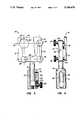
- FIG. 3illustrates a front elevational view of an optical mounting apparatus constructed in accordance with the principles of the present invention, shown with a portion of the mounting post in cross-section.
- FIG. 4is a side elevational view of the optical mounting apparatus of FIG. 3.
- FIG. 5is an exploded view of the base plate and stage plate of the optical mounting apparatus of FIGS. 3 and 4.
- FIG. 6is an exploded view of the adjustable height and mounting post of the optical mounting apparatus of FIGS. 3 and 4.
- FIGS. 3 and 4An optical mounting apparatus 10 constructed in accordance with the principles the present invention is illustrated in FIGS. 3 and 4.
- the apparatus 10includes an upper support assembly 12 (illustrated in detail in FIG. 5) and a lower post assembly 14 (illustrated in detail in FIG. 6).
- An optical element mounting region 16is located on the upper support assembly 12, and the upper support assembly 12 allows for rotational adjustment of the mounting region 16 about both a horizontal axis 18 and a vertical axis 20, as will be described in greater detail hereinafter.
- the lower post assembly 14provides for vertical translational adjustment of the mounting region 16, as will also be described in greater detail hereinafter.
- the upper support assembly 12includes a stage plate 21 and a baseplate 22.
- the baseplate 22includes means for attachment to the lower post assembly, such as an attachment hole 24 capable of receiving an attachment screw 26 (FIG. 3).
- a second (alternate) attachment hole 25is provided so that the stage plate 21 may be rotated by 90° to move the mounting region 16 relative to the lower post assembly 14.
- other attachment meanssuch as snaps, clamps, anchors, and the like, could be employed.
- the upper support assembly 12 and lower post assembly 14could be permanently affixed, such as by welding, the use of adhesives, and the like.
- the baseplate 22includes three threaded ports 28, 30, and 32 capable of receiving three adjustment screws 34, 36, and 38, respectively.
- the threaded ports 28, 30, and 32are arranged at the corners of a right triangle and are usually equidistant from each other.
- the baseplate 22has an L-shaped configuration with the threaded ports 28, 30, and 32 located at the extremities of and junction between the two legs of the "L.”
- Baseplate 22could have a wide variety of other configurations, but the L-shaped configuration is convenient since it avoids interference with the optical element mounting region 16 on the stageplate 21.
- the stageplate 21is held to the baseplate 22 by a pair of coil springs 40 and 42 which are maintained under tension so that a gap 44 (FIG. 4) between the plates would have a tendency to close in the absence of the adjustment screws 34, 36, and 38. That is, it is the force provided by the adjustment screws 34, 36, and 38 which maintains the gap 44, and to the extent the adjustment screws are moved away from the stageplate 21 (i.e. to the left in FIG. 4), the gap 44 will diminish.
- the springs 40 and 42will be located so that the compressive force is equally distributed between the three adjustment screws 34, 36, and 38.
- the adjustment screws 34, 36, and 38engage the stageplate 21 in shallow receptacles 50, 52, and 54 which are coplanar and formed in surface 56 of the stageplate which is disposed toward the baseplate 22.
- coil springs 40 and 42are received in attachment receptacles 56 and 58, respectively.
- the center 60 of mounting region 16is located at a corner of a rectangle, usually a square, which is defined by the locations of the shallow receptacles 50, 52, and 54. It is this location of the optical mounting region which, in part, distinguishes the mounting apparatus of the present invention from that of the prior art.
- the center 60 of the mounting regiondefines a datum point which can be rotationally adjusted about both the horizontal axis 18 and the vertical axis 20, without any significant translation of the datum in a direction normal to the plane defined by baseplate 22.
- the datum 60 of optical mounting region 16may be rotated relative to the horizontal axis 18 by translating adjustment screws 36 and 38 in the direction relative to the plane defined by baseplate 22.
- Rotation of the datum 60 and optical mounting region 16 about the vertical axis 20may be achieved by adjustment of screws 34 and 36, without any adjustment of screw 38. Adjustment of screws 34 and 36 to allow stageplate 21 to move closer to baseplate 22 causes the datum to rotate in a first direction, while adjustment that causes the stageplate to move away from the baseplate causes the datum to rotate in the opposite direction.
- the optical mounting region 16is illustrated a an aperture stage plate 21. It will be appreciated that the mounting region may comprise a wide variety of other configurations which permit mounting of the desired optical element, such as a mirror, lens, diffraction grating, beam splitter, and the like on the stageplate 21.
- the lower post assembly 14includes a casing 70 having an axial cylindrical hole 72 with a distal opening 74 and side aperture 76.
- a mounting hole 78is formed at a proximal end of the casing 70 and is suitable for mounting the casing on any flat surface using, e.g., a mounting screw (not illustrated). While usually the flat surface would be horizontal, it will be appreciated that the surface can assume virtually any orientation.
- a lever arm 80is received in a slot 82 formed in a side of the casing 70 adjacent the side aperture 76.
- Lever 80includes shoulder 84 at a proximal end thereof, and shoulder 84 is sized so that it fits into aperture 76 when the lever arm 80 is in place in slot 82.
- the shoulder 84is pivotally mounted on a pin 86 which passes through a bearing cylindrical hole 88 in the shoulder and into pin receptacles 90 (only one of which is illustrated) in the casing 70.
- a cylindrical rod 94 having a mounting hole 96 at its upper endis slidably received in the cylindrical hole 72 of casing 70.
- the upper support assembly 12may be secured to the rod 94 using screw 26 which is received in mounting hole 96, as best observed in FIG. 3.
- the shoulder 84 of lever 80includes a cylindrically concave surface 98 having a curvature which corresponds generally to the exterior of rod 94.
- the surface 98will be generally parallel to the exterior rod 94, allowing the rod to move freely in cylindrical hole 72.
- the surface 98will cant against the exterior of rod 94, thus locking rod 94 in place.
- a compressed spring 100is provided between the casing 70 and the lever arm 80 (being received in a receptacle 102 in the lever arm), causing the surface 98 to cant against the rod 94 when the support assembly 12 is in its "shelf" condition. That is, so long as a support assembly is undisturbed, the rod 94 will be in a generally locked configuration. The user, however, may free the rod 94 by simply depressing the proximal end of lever 80 toward the casing 70. Such depression relieves the canting of surface 98 and allows the rod to move freely in cylindrical hole 72.
- the rod 94may be locked against further inadvertent changes by use of a locking screw 106 which is threadably received to the proximal end of lever arm 80.
- Locking screw 106can be rotated so that is extends toward the casing 70, thus moving the proximal end of the lever away from the casing.
- the lever arm 80is thus locked, the user cannot accidentally depress the proximal end to inadvertently release the rod 94.
- coil spring 100can be placed by a variety of other elastic elements, such as leaf springs, and the like.
Landscapes
- Physics & Mathematics (AREA)
- General Physics & Mathematics (AREA)
- Optics & Photonics (AREA)
- Mounting And Adjusting Of Optical Elements (AREA)
- Optical Couplings Of Light Guides (AREA)
- Lens Barrels (AREA)
Abstract
Description
Claims (21)
Priority Applications (5)
| Application Number | Priority Date | Filing Date | Title |
|---|---|---|---|
| US07/638,886US5140470A (en) | 1991-01-07 | 1991-01-07 | Optical mounting apparatus |
| PCT/US1992/000041WO1992012450A2 (en) | 1991-01-07 | 1992-01-03 | Improved optical mounting apparatus |
| JP4504441AJPH06507026A (en) | 1991-01-07 | 1992-01-03 | Improved optical mounting device |
| AU11975/92AAU1197592A (en) | 1991-01-07 | 1992-01-03 | Improved optical mounting apparatus |
| EP19920904119EP0566660A4 (en) | 1991-01-07 | 1992-01-03 | Improved optical mounting apparatus |
Applications Claiming Priority (1)
| Application Number | Priority Date | Filing Date | Title |
|---|---|---|---|
| US07/638,886US5140470A (en) | 1991-01-07 | 1991-01-07 | Optical mounting apparatus |
Publications (1)
| Publication Number | Publication Date |
|---|---|
| US5140470Atrue US5140470A (en) | 1992-08-18 |
Family
ID=24561862
Family Applications (1)
| Application Number | Title | Priority Date | Filing Date |
|---|---|---|---|
| US07/638,886Expired - LifetimeUS5140470A (en) | 1991-01-07 | 1991-01-07 | Optical mounting apparatus |
Country Status (5)
| Country | Link |
|---|---|
| US (1) | US5140470A (en) |
| EP (1) | EP0566660A4 (en) |
| JP (1) | JPH06507026A (en) |
| AU (1) | AU1197592A (en) |
| WO (1) | WO1992012450A2 (en) |
Cited By (50)
| Publication number | Priority date | Publication date | Assignee | Title |
|---|---|---|---|---|
| WO1993023800A1 (en)* | 1992-05-08 | 1993-11-25 | New Focus, Inc. | Precision component positioner |
| USD344966S (en) | 1992-06-03 | 1994-03-08 | Friedman Arthur S | Lens mount |
| US5410206A (en)* | 1993-04-06 | 1995-04-25 | New Focus, Inc. | Piezoelectric actuator for optical alignment screws |
| US5530547A (en)* | 1994-08-04 | 1996-06-25 | Arnold; Steven M. | Method and apparatus for aligning optical elements and testing aspheric optical components |
| EP0729193A1 (en)* | 1995-02-27 | 1996-08-28 | New Focus, Inc. | Piezoelectric actuator for optical alignment screws |
| US5724181A (en)* | 1996-12-18 | 1998-03-03 | Asia Optical Co., Ltd. | Sight scope |
| US5757561A (en)* | 1996-11-26 | 1998-05-26 | Newport Corporation | Precision optical mounts |
| US5847885A (en)* | 1997-06-18 | 1998-12-08 | New Focus, Inc. | Wide range cylindrical mirror mount with radial clamp |
| WO1999046622A1 (en)* | 1998-03-11 | 1999-09-16 | Newport Corporation | Optical mount with a locking adjustment screw |
| US6061190A (en)* | 1999-03-11 | 2000-05-09 | Optics For Research | Devices for holding optical components at fixed positions |
| DE10031870A1 (en)* | 2000-06-30 | 2002-01-10 | Diehl Munitionssysteme Gmbh | Optronic ignition device for weapon system has sensor mounted adjustably in weapon system with three-point bearing containing mounting plate and adjustable, fixable bearing plate |
| US6438461B1 (en) | 1999-02-23 | 2002-08-20 | Newport Corporation | Method and device for displacing a moving body on a base mounted elastically with respect to the ground |
| US6511035B1 (en) | 1999-08-03 | 2003-01-28 | Newport Corporation | Active vibration isolation systems with nonlinear compensation to account for actuator saturation |
| US6516130B1 (en) | 1998-12-30 | 2003-02-04 | Newport Corporation | Clip that aligns a fiber optic cable with a laser diode within a fiber optic module |
| US6568666B2 (en) | 2001-06-13 | 2003-05-27 | Newport Corporation | Method for providing high vertical damping to pneumatic isolators during large amplitude disturbances of isolated payload |
| US6601524B2 (en) | 2001-03-28 | 2003-08-05 | Newport Corporation | Translation table with a spring biased dovetail bearing |
| US6614601B2 (en) | 1998-08-17 | 2003-09-02 | Newport Corporation | Gimballed optical mount |
| US6619611B2 (en) | 2001-07-02 | 2003-09-16 | Newport Corporation | Pneumatic vibration isolator utilizing an elastomeric element for isolation and attenuation of horizontal vibration |
| US6655840B2 (en) | 2001-02-13 | 2003-12-02 | Newport Corporation | Stiff cross roller bearing configuration |
| US6744575B1 (en) | 2002-11-12 | 2004-06-01 | Axon Instruments, Inc. | Optical mount and method for use thereof |
| US6791058B2 (en) | 2001-04-25 | 2004-09-14 | Newport Corporation | Automatic laser weld machine for assembling photonic components |
| US20040190164A1 (en)* | 2003-03-28 | 2004-09-30 | Bentley Joseph R. | Lens mount |
| US6966535B2 (en) | 2002-05-07 | 2005-11-22 | Newport Corporation | Snubber for pneumatically isolated platforms |
| US6996506B2 (en) | 1999-02-23 | 2006-02-07 | Newport Corporation | Process and device for displacing a moveable unit on a base |
| US20060133994A1 (en)* | 1998-05-11 | 2006-06-22 | Dario Neri | Specific binding molecules for scintigraphy, conjugates containing them and therapeutic method for treatment of angiogenesis |
| US20070065086A1 (en)* | 2005-09-19 | 2007-03-22 | Mike Wyatt | Adjustable support device for optical components and methods of use |
| US20070164177A1 (en)* | 2005-11-14 | 2007-07-19 | Ashbury International Group, Inc. | Optical equipment mounting devices and systems |
| US7320455B2 (en) | 2003-10-24 | 2008-01-22 | Newport Corporation | Instrumented platform for vibration-sensitive equipment |
| DE102007010222A1 (en) | 2007-02-28 | 2008-09-04 | Medialas Laserproducts Gmbh | Laser device for producing laser beam, has two laser partial beam unit, where adjustable mirror is fastened to mounting plate for twisting one laser partial beam to merge two laser partial beam to one laser beam |
| US20100131015A1 (en)* | 2008-11-21 | 2010-05-27 | Eugeniusz Kozak | Spring-loaded kinematic adjustment screw |
| US20100290138A1 (en)* | 2007-01-18 | 2010-11-18 | Newport Corporation | Optical adjustment mounts with piezoelectric inertia driver |
| US20120032055A1 (en)* | 2010-08-09 | 2012-02-09 | Sigma Space Corporation | Directionally adjustable mount with locking parts and methods |
| US8231098B2 (en) | 2004-12-07 | 2012-07-31 | Newport Corporation | Methods and devices for active vibration damping of an optical structure |
| US8482868B2 (en) | 2010-07-15 | 2013-07-09 | Newport Corporation | Optical adjustable mounts with absolute position feedback |
| US20150125164A1 (en)* | 2013-11-06 | 2015-05-07 | Hisense Co., Ltd. | Optical Apparatus |
| US20150362694A1 (en)* | 2013-02-01 | 2015-12-17 | Newport Corporation | Optical post mount system and method of use |
| US9312790B2 (en) | 2013-09-13 | 2016-04-12 | Physik Instrumente (Pi) Gmbh & Co. Kg | Compact versatile stick-slip piezoelectric motor |
| US20160187609A1 (en)* | 2014-12-24 | 2016-06-30 | Newport Corporation | System and method for mounting and aligning optical components using single-rail mounting |
| US9425711B2 (en) | 2014-04-15 | 2016-08-23 | Newport Corporation | Integral preload mechanism for piezoelectric actuator |
| WO2017049257A1 (en)* | 2015-09-18 | 2017-03-23 | Newport Corp | Optical component mount system for use with an optical rail system |
| CN109073836A (en)* | 2016-02-12 | 2018-12-21 | 纽波特公司 | Optical component mounting device and struts and application method |
| US10161560B2 (en) | 2015-01-29 | 2018-12-25 | Newport Corporation | Integrated picomotor mount |
| US10437084B1 (en)* | 2017-05-23 | 2019-10-08 | Lockheed Martin Coherent Technologies, Inc. | Electro-optical crystal-mounted apparatus and systems for use in laser cavities/assemblies |
| EP3722855A1 (en)* | 2019-04-09 | 2020-10-14 | BAE SYSTEMS plc | A mount |
| WO2020208335A1 (en)* | 2019-04-09 | 2020-10-15 | Bae Systems Plc | A mount |
| US10996419B2 (en) | 2017-07-31 | 2021-05-04 | Newport Corporation | Thermal compensating optical component mount and related devices |
| US11269170B2 (en)* | 2018-12-28 | 2022-03-08 | Chroma Ate Inc. | Separate microscopy system and adjusting method thereof |
| US11293624B2 (en)* | 2016-02-11 | 2022-04-05 | In Tandem Designs Pty Ltd | Light source |
| CN114609749A (en)* | 2022-05-16 | 2022-06-10 | 季华实验室 | A mirror frame and its application method |
| US11482658B1 (en) | 2018-06-06 | 2022-10-25 | Government Of The United States As Represented By The Secretary Of The Air Force | Piezoelectric rotary optical mount |
Families Citing this family (2)
| Publication number | Priority date | Publication date | Assignee | Title |
|---|---|---|---|---|
| GB2334593B (en)* | 1998-02-20 | 2002-07-17 | Melles Griot Ltd | Positioning mechanism |
| FR2931980A1 (en)* | 2008-05-29 | 2009-12-04 | Denis Dutrop | Barrier or perimeter type alarm device for e.g. outdoor swimming pool, has mirrors mounted on plastic plate by fixed screw and adjustment screws, where plate is fixed to vertical post of considered terminal |
Citations (5)
| Publication number | Priority date | Publication date | Assignee | Title |
|---|---|---|---|---|
| US3893138A (en)* | 1972-08-28 | 1975-07-01 | Hasselblad Fritz Victor | Accessory socket for interchangeable lens for photographic cameras |
| JPS62907A (en)* | 1985-06-27 | 1987-01-06 | Ricoh Co Ltd | Angle adjusting device for optical parts mounting plate |
| US4842397A (en)* | 1986-12-03 | 1989-06-27 | Gyula Eisler | Apparatus for adjusting the angular position of optical elements |
| US4913527A (en)* | 1988-09-19 | 1990-04-03 | Eastman Kodak Company | Lens focus adjustment means |
| US4988165A (en)* | 1988-05-25 | 1991-01-29 | Sharp Kabushiki Kaisha | Object lens driving device |
Family Cites Families (3)
| Publication number | Priority date | Publication date | Assignee | Title |
|---|---|---|---|---|
| JPS61132936A (en)* | 1984-11-30 | 1986-06-20 | Asahi Optical Co Ltd | Lens barrel with lens shutter |
| JPH087868B2 (en)* | 1986-07-10 | 1996-01-29 | 松下電器産業株式会社 | Optical signal readout device |
| JPH01259309A (en)* | 1988-04-08 | 1989-10-17 | Minolta Camera Co Ltd | Adjusting mechanism for alignment of semiconductor laser and collimator lens, and focusing mechanism |
- 1991
- 1991-01-07USUS07/638,886patent/US5140470A/ennot_activeExpired - Lifetime
- 1992
- 1992-01-03AUAU11975/92Apatent/AU1197592A/ennot_activeAbandoned
- 1992-01-03EPEP19920904119patent/EP0566660A4/ennot_activeCeased
- 1992-01-03JPJP4504441Apatent/JPH06507026A/enactivePending
- 1992-01-03WOPCT/US1992/000041patent/WO1992012450A2/ennot_activeApplication Discontinuation
Patent Citations (5)
| Publication number | Priority date | Publication date | Assignee | Title |
|---|---|---|---|---|
| US3893138A (en)* | 1972-08-28 | 1975-07-01 | Hasselblad Fritz Victor | Accessory socket for interchangeable lens for photographic cameras |
| JPS62907A (en)* | 1985-06-27 | 1987-01-06 | Ricoh Co Ltd | Angle adjusting device for optical parts mounting plate |
| US4842397A (en)* | 1986-12-03 | 1989-06-27 | Gyula Eisler | Apparatus for adjusting the angular position of optical elements |
| US4988165A (en)* | 1988-05-25 | 1991-01-29 | Sharp Kabushiki Kaisha | Object lens driving device |
| US4913527A (en)* | 1988-09-19 | 1990-04-03 | Eastman Kodak Company | Lens focus adjustment means |
Cited By (78)
| Publication number | Priority date | Publication date | Assignee | Title |
|---|---|---|---|---|
| WO1993023800A1 (en)* | 1992-05-08 | 1993-11-25 | New Focus, Inc. | Precision component positioner |
| US5282393A (en)* | 1992-05-08 | 1994-02-01 | New Focus, Inc. | Precision component positioner |
| US5400674A (en)* | 1992-05-08 | 1995-03-28 | New Focus, Inc. | Precision component positioner |
| USD344966S (en) | 1992-06-03 | 1994-03-08 | Friedman Arthur S | Lens mount |
| US5410206A (en)* | 1993-04-06 | 1995-04-25 | New Focus, Inc. | Piezoelectric actuator for optical alignment screws |
| US5530547A (en)* | 1994-08-04 | 1996-06-25 | Arnold; Steven M. | Method and apparatus for aligning optical elements and testing aspheric optical components |
| EP0729193A1 (en)* | 1995-02-27 | 1996-08-28 | New Focus, Inc. | Piezoelectric actuator for optical alignment screws |
| US5930057A (en)* | 1996-11-26 | 1999-07-27 | Newport Corporation | Precision optical mounts |
| US6304393B1 (en) | 1996-11-26 | 2001-10-16 | Newport Corporation | Precision optical mounts |
| US5757561A (en)* | 1996-11-26 | 1998-05-26 | Newport Corporation | Precision optical mounts |
| US5724181A (en)* | 1996-12-18 | 1998-03-03 | Asia Optical Co., Ltd. | Sight scope |
| US5847885A (en)* | 1997-06-18 | 1998-12-08 | New Focus, Inc. | Wide range cylindrical mirror mount with radial clamp |
| US5953164A (en)* | 1997-06-18 | 1999-09-14 | New Focus, Inc. | Wide range cylindrical mirror mount with radial clamp |
| WO1999046622A1 (en)* | 1998-03-11 | 1999-09-16 | Newport Corporation | Optical mount with a locking adjustment screw |
| US6016230A (en)* | 1998-03-11 | 2000-01-18 | Newport Corporation | Optical mount with a locking adjustment screw |
| US20060133994A1 (en)* | 1998-05-11 | 2006-06-22 | Dario Neri | Specific binding molecules for scintigraphy, conjugates containing them and therapeutic method for treatment of angiogenesis |
| US6614601B2 (en) | 1998-08-17 | 2003-09-02 | Newport Corporation | Gimballed optical mount |
| US6516130B1 (en) | 1998-12-30 | 2003-02-04 | Newport Corporation | Clip that aligns a fiber optic cable with a laser diode within a fiber optic module |
| US6608959B2 (en) | 1998-12-30 | 2003-08-19 | Newport Corporation | Apparatus and process for welding a fiber optic cable |
| US6438461B1 (en) | 1999-02-23 | 2002-08-20 | Newport Corporation | Method and device for displacing a moving body on a base mounted elastically with respect to the ground |
| US6996506B2 (en) | 1999-02-23 | 2006-02-07 | Newport Corporation | Process and device for displacing a moveable unit on a base |
| US6061190A (en)* | 1999-03-11 | 2000-05-09 | Optics For Research | Devices for holding optical components at fixed positions |
| US6511035B1 (en) | 1999-08-03 | 2003-01-28 | Newport Corporation | Active vibration isolation systems with nonlinear compensation to account for actuator saturation |
| DE10031870A1 (en)* | 2000-06-30 | 2002-01-10 | Diehl Munitionssysteme Gmbh | Optronic ignition device for weapon system has sensor mounted adjustably in weapon system with three-point bearing containing mounting plate and adjustable, fixable bearing plate |
| US6655840B2 (en) | 2001-02-13 | 2003-12-02 | Newport Corporation | Stiff cross roller bearing configuration |
| US6601524B2 (en) | 2001-03-28 | 2003-08-05 | Newport Corporation | Translation table with a spring biased dovetail bearing |
| US6791058B2 (en) | 2001-04-25 | 2004-09-14 | Newport Corporation | Automatic laser weld machine for assembling photonic components |
| US6568666B2 (en) | 2001-06-13 | 2003-05-27 | Newport Corporation | Method for providing high vertical damping to pneumatic isolators during large amplitude disturbances of isolated payload |
| US6619611B2 (en) | 2001-07-02 | 2003-09-16 | Newport Corporation | Pneumatic vibration isolator utilizing an elastomeric element for isolation and attenuation of horizontal vibration |
| US6966535B2 (en) | 2002-05-07 | 2005-11-22 | Newport Corporation | Snubber for pneumatically isolated platforms |
| US6744575B1 (en) | 2002-11-12 | 2004-06-01 | Axon Instruments, Inc. | Optical mount and method for use thereof |
| US6785067B1 (en) | 2002-11-12 | 2004-08-31 | Axon Instruments, Inc. | Optical mount and method for use thereof |
| WO2004088383A1 (en)* | 2003-03-28 | 2004-10-14 | Bausch & Lomb Incorporated | Adjustable lens mount |
| US20040190164A1 (en)* | 2003-03-28 | 2004-09-30 | Bentley Joseph R. | Lens mount |
| US7320455B2 (en) | 2003-10-24 | 2008-01-22 | Newport Corporation | Instrumented platform for vibration-sensitive equipment |
| US8651447B2 (en) | 2004-12-07 | 2014-02-18 | Newport Corporation | Methods and devices for active vibration damping of an optical structure |
| US8231098B2 (en) | 2004-12-07 | 2012-07-31 | Newport Corporation | Methods and devices for active vibration damping of an optical structure |
| US7400802B2 (en)* | 2005-09-19 | 2008-07-15 | Newport Corporation | Adjustable support device for optical components and methods of use |
| US20070065086A1 (en)* | 2005-09-19 | 2007-03-22 | Mike Wyatt | Adjustable support device for optical components and methods of use |
| US8066236B2 (en) | 2005-11-14 | 2011-11-29 | Ashbury International Group, Inc. | Optical equipment mounting devices and systems |
| US20070164177A1 (en)* | 2005-11-14 | 2007-07-19 | Ashbury International Group, Inc. | Optical equipment mounting devices and systems |
| WO2007089363A3 (en)* | 2005-11-14 | 2007-11-22 | Ashbury Internat Group Inc | Optical equipment mounting devices and systems |
| US20100290138A1 (en)* | 2007-01-18 | 2010-11-18 | Newport Corporation | Optical adjustment mounts with piezoelectric inertia driver |
| US8520327B2 (en) | 2007-01-18 | 2013-08-27 | Newport Corporation | Optical adjustment mounts with piezoelectric inertia driver |
| DE102007010222A1 (en) | 2007-02-28 | 2008-09-04 | Medialas Laserproducts Gmbh | Laser device for producing laser beam, has two laser partial beam unit, where adjustable mirror is fastened to mounting plate for twisting one laser partial beam to merge two laser partial beam to one laser beam |
| US20100131015A1 (en)* | 2008-11-21 | 2010-05-27 | Eugeniusz Kozak | Spring-loaded kinematic adjustment screw |
| US8235636B2 (en) | 2008-11-21 | 2012-08-07 | Eugeniusz Kozak | Spring-loaded kinematic adjustment screw |
| US8482868B2 (en) | 2010-07-15 | 2013-07-09 | Newport Corporation | Optical adjustable mounts with absolute position feedback |
| US8755133B2 (en) | 2010-07-15 | 2014-06-17 | Newport Corporation | Optical adjustable mounts with absolute position feedback |
| US20120032055A1 (en)* | 2010-08-09 | 2012-02-09 | Sigma Space Corporation | Directionally adjustable mount with locking parts and methods |
| US8366063B2 (en)* | 2010-08-09 | 2013-02-05 | Sigma Space Corporation | Directionally adjustable mount with locking parts and methods |
| US9678300B2 (en)* | 2013-02-01 | 2017-06-13 | Newport Corporation | Optical post mount system and method of use |
| US20150362694A1 (en)* | 2013-02-01 | 2015-12-17 | Newport Corporation | Optical post mount system and method of use |
| US10241290B2 (en) | 2013-02-01 | 2019-03-26 | Newport Corporation | Optical post mount system and method of use |
| US9312790B2 (en) | 2013-09-13 | 2016-04-12 | Physik Instrumente (Pi) Gmbh & Co. Kg | Compact versatile stick-slip piezoelectric motor |
| US20150125164A1 (en)* | 2013-11-06 | 2015-05-07 | Hisense Co., Ltd. | Optical Apparatus |
| US10133025B2 (en) | 2013-11-06 | 2018-11-20 | Hisense Co., Ltd. | Optical apparatus capable of external calibration for optical device |
| US9606322B2 (en)* | 2013-11-06 | 2017-03-28 | Hisense Co., Ltd. | Optical apparatus capable of external calibration for optical device |
| US9425711B2 (en) | 2014-04-15 | 2016-08-23 | Newport Corporation | Integral preload mechanism for piezoelectric actuator |
| US10389276B2 (en) | 2014-04-15 | 2019-08-20 | Newport Corporation | Integral preload mechanism for piezoelectric actuator |
| US9964728B2 (en)* | 2014-12-24 | 2018-05-08 | Newport Corporation | System and method for mounting and aligning optical components using single-rail mounting |
| US20180217347A1 (en)* | 2014-12-24 | 2018-08-02 | Newport Corporation | System and method for mounting and aligning different size optical components using linked-rail mounting |
| US10684440B2 (en)* | 2014-12-24 | 2020-06-16 | Newport Corporation | System and method for mounting and aligning different size optical components using linked-rail mounting |
| US10684439B2 (en) | 2014-12-24 | 2020-06-16 | Newport Corporation | System and method for mounting and aligning optical components with respect to junction optical component |
| US20160187609A1 (en)* | 2014-12-24 | 2016-06-30 | Newport Corporation | System and method for mounting and aligning optical components using single-rail mounting |
| US10161560B2 (en) | 2015-01-29 | 2018-12-25 | Newport Corporation | Integrated picomotor mount |
| CN108431659A (en)* | 2015-09-18 | 2018-08-21 | 纽波特公司 | Optical component stent system for being used together with optical rail system |
| WO2017049257A1 (en)* | 2015-09-18 | 2017-03-23 | Newport Corp | Optical component mount system for use with an optical rail system |
| US11293624B2 (en)* | 2016-02-11 | 2022-04-05 | In Tandem Designs Pty Ltd | Light source |
| CN109073836A (en)* | 2016-02-12 | 2018-12-21 | 纽波特公司 | Optical component mounting device and struts and application method |
| US10437084B1 (en)* | 2017-05-23 | 2019-10-08 | Lockheed Martin Coherent Technologies, Inc. | Electro-optical crystal-mounted apparatus and systems for use in laser cavities/assemblies |
| US10996419B2 (en) | 2017-07-31 | 2021-05-04 | Newport Corporation | Thermal compensating optical component mount and related devices |
| US11482658B1 (en) | 2018-06-06 | 2022-10-25 | Government Of The United States As Represented By The Secretary Of The Air Force | Piezoelectric rotary optical mount |
| US11269170B2 (en)* | 2018-12-28 | 2022-03-08 | Chroma Ate Inc. | Separate microscopy system and adjusting method thereof |
| EP3722855A1 (en)* | 2019-04-09 | 2020-10-14 | BAE SYSTEMS plc | A mount |
| WO2020208335A1 (en)* | 2019-04-09 | 2020-10-15 | Bae Systems Plc | A mount |
| US11821570B2 (en) | 2019-04-09 | 2023-11-21 | Bae Systems Plc | Mount for adjusting a mounting plane |
| CN114609749A (en)* | 2022-05-16 | 2022-06-10 | 季华实验室 | A mirror frame and its application method |
Also Published As
| Publication number | Publication date |
|---|---|
| EP0566660A1 (en) | 1993-10-27 |
| JPH06507026A (en) | 1994-08-04 |
| WO1992012450A2 (en) | 1992-07-23 |
| EP0566660A4 (en) | 1993-11-18 |
| AU1197592A (en) | 1992-08-17 |
| WO1992012450A3 (en) | 1992-08-20 |
Similar Documents
| Publication | Publication Date | Title |
|---|---|---|
| US5140470A (en) | Optical mounting apparatus | |
| US6614601B2 (en) | Gimballed optical mount | |
| US5330147A (en) | Video monitor clamp | |
| US2168988A (en) | Adjustable tripod head | |
| GB2189210A (en) | Counterbalanced support | |
| US3814365A (en) | Adjustable mirror mount | |
| US4302179A (en) | Burner holder with quick release and lockup mechanism | |
| US4770382A (en) | Stand for display terminals in particular | |
| US5505422A (en) | Top adjustable kinematic mount | |
| US3879112A (en) | Adjustable mirror mount | |
| US4863243A (en) | Mount for an optical element including a holder with a generally semicylindrical surface | |
| GB2136145A (en) | Adjustable mounting for an optical element | |
| US6323903B1 (en) | Three axis camera mount | |
| US4880301A (en) | Mount for an optical element | |
| US5523883A (en) | Field adjustable beam splitter | |
| US7520063B2 (en) | Device with precise tip-tilt adjustment | |
| US20030039506A1 (en) | Elbow connector structure for a cymbal support | |
| US4896857A (en) | Vernier adjustment system for dial indicator holder | |
| US4183627A (en) | Adjusting device for adjusting the position of an optical or opto-electronic component in two directions of adjustment which are perpendicular to each other | |
| US4405120A (en) | Printed circuit board holder | |
| US4712444A (en) | Levered optical mount | |
| US6590723B1 (en) | Optical instrument mount | |
| GB2364240A (en) | Horizontally and vertically adjustable monitor stand | |
| US4278320A (en) | Binocular stand for astronomical observations | |
| US20070091488A1 (en) | Optical element mount |
Legal Events
| Date | Code | Title | Description |
|---|---|---|---|
| AS | Assignment | Owner name:NEW FOCUS, INC., 340 PIONEER WAY MOUNTAIN VIEW, CA Free format text:ASSIGNMENT OF ASSIGNORS INTEREST.;ASSIGNOR:LUECKE, FRANCIS S.;REEL/FRAME:005574/0912 Effective date:19910104 | |
| STCF | Information on status: patent grant | Free format text:PATENTED CASE | |
| FPAY | Fee payment | Year of fee payment:4 | |
| FEPP | Fee payment procedure | Free format text:PAYOR NUMBER ASSIGNED (ORIGINAL EVENT CODE: ASPN); ENTITY STATUS OF PATENT OWNER: LARGE ENTITY | |
| FPAY | Fee payment | Year of fee payment:8 | |
| FEPP | Fee payment procedure | Free format text:PAT HLDR NO LONGER CLAIMS SMALL ENT STAT AS INDIV INVENTOR (ORIGINAL EVENT CODE: LSM1); ENTITY STATUS OF PATENT OWNER: LARGE ENTITY | |
| FEPP | Fee payment procedure | Free format text:PAT HOLDER CLAIMS SMALL ENTITY STATUS, ENTITY STATUS SET TO SMALL (ORIGINAL EVENT CODE: LTOS); ENTITY STATUS OF PATENT OWNER: LARGE ENTITY | |
| FPAY | Fee payment | Year of fee payment:12 | |
| REMI | Maintenance fee reminder mailed | ||
| FEPP | Fee payment procedure | Free format text:PAT HOLDER NO LONGER CLAIMS SMALL ENTITY STATUS, ENTITY STATUS SET TO UNDISCOUNTED (ORIGINAL EVENT CODE: STOL); ENTITY STATUS OF PATENT OWNER: LARGE ENTITY | |
| AS | Assignment | Owner name:NEWPORT CORPORATION, CALIFORNIA Free format text:ASSIGNMENT OF ASSIGNORS INTEREST;ASSIGNOR:NEW FOCUS, INC.;REEL/FRAME:023627/0985 Effective date:20090703 |