US5140416A - System and method for fusing video imagery from multiple sources in real time - Google Patents
System and method for fusing video imagery from multiple sources in real timeDownload PDFInfo
- Publication number
- US5140416A US5140416AUS07/583,980US58398090AUS5140416AUS 5140416 AUS5140416 AUS 5140416AUS 58398090 AUS58398090 AUS 58398090AUS 5140416 AUS5140416 AUS 5140416A
- Authority
- US
- United States
- Prior art keywords
- sensor
- signals
- background
- responsive
- signal
- Prior art date
- Legal status (The legal status is an assumption and is not a legal conclusion. Google has not performed a legal analysis and makes no representation as to the accuracy of the status listed.)
- Expired - Lifetime
Links
Images


Classifications
- G—PHYSICS
- G06—COMPUTING OR CALCULATING; COUNTING
- G06T—IMAGE DATA PROCESSING OR GENERATION, IN GENERAL
- G06T5/00—Image enhancement or restoration
- G06T5/50—Image enhancement or restoration using two or more images, e.g. averaging or subtraction
Definitions
- This inventionrelates to a system and method for imaging a scene with plural sensors sensitive to different scene characteristics, determining the best features received from each sensor and then fusing or merging imagery of the best features from the multiple sensors to provide an image having improved information content.
- Image sensors employed in present day military and scientific environmentsattempt to extract as much information about a scene under observation as possible. In order to perform this function, it is necessary to interrogate the scene being observed with as many different types of sensors as is feasible. Visible, infra-red and image intensified sensors represent three of the most common passive imaging sensors utilized in the military environment. Each sensor detects different information about the imaged scene.
- ROLPRaster of Low-Pass pyramid
- decimationis a common digital signal processing technique for downsampling or sample rate reduction. For example, if a signal is decimated by 4, every fourth sample is retained and the rest are discarded. It again does not lend itself to reasonable real-time hardware implementations.
- the system and method in accordance with the present inventionfuses or merges video imagery from multiple sources such that the resultant image has improved information content over any one of the individual video images.
- the sensors generating the video imageryare typically responsive to different spectral content in the scene being scanned, such as visible and infra-red or short and long wavelength infra-red, and the like.
- the inventioncan also be applied to non-passive sensors, such as imaging RADAR or Laser RADAR (LADAR). This permits real-time, high pixel rate operation with hardware implementation of moderate cost and complexity.
- Image enhancement by frequency content specificationis another advantage of this approach. The flexibility permits application to many different video formats and line rates.
- the systemgenerates fused or merged imagery from two or more video sources in real-time.
- the disclosure hereinwill be presented with reference to two different video sources, it being understood that more than two different video sources can be used.
- the two sensor fields of vieware aligned and are either identical or subsets of one another.
- the fusion hardwareaccepts digitized pixel aligned data from each sensor and generates a single output which is the fused resultant image therefrom.
- an image fusion circuit in accordance with the present inventionprovides a fused video output and receives two different digital video inputs from the sensor field.
- the sensor fieldsare aligned and are either identical or subsets of one another.
- the systemaccepts digitized pixel aligned data from each sensor at the feature/background separation circuit which separates the video signals from input into features and backgrounds.
- pixel alignmentmeans that a pixel being input on a first digital video input represents the same portion of a scene being scanned as the pixel being simultaneously input on the second digital video input.
- the featuresare the information or the high frequency or the detail in the scene being scanned, such as, for example, the edges of buildings.
- the backgroundis the shading and more subtle levels to the scene. The background is selected or generated on a global basis.
- the feature/background selection circuitgenerates the features from each of the first and second inputs on separate lines to a local area feature selection circuit.
- the feature/background selection circuitgenerates the background from each of the first and second inputs on separate lines to a global background selection circuit.
- the feature selection circuitselects the appropriate, principal or best feature at each pixel and sends a single composite feature video stream signal indicative thereof to the feature/background merge circuit.
- the background selection circuitselects the appropriate background at each pixel and sends a single composite background video stream signal indicative thereof to the feature/background merge circuit. These video streams are then merged into a final composite fused video output by the feature/background merge circuit.
- the video outputis displayed on a cathode ray tube or the like to provide the enhanced image thereon.
- FIG. 1is a block diagram of an image fusion circuit in accordance with the present invention
- FIG. 2is a block diagram of the feature/background separation circuit of FIG. 1 in accordance with the present invention.
- FIG. 3is a block diagram of the feature selection circuit of FIG. 1 in accordance with the present invention.
- FIG. 4is a block diagram of the background selection circuit of FIGURE 1 in accordance with the present invention.
- FIG. 5is a block diagram of the feature/background merge circuit of FIG. 1 in accordance with the present invention.
- FIG. 6is a two dimensional low-pass frequency response curve for the FIR of FIG. 2;
- FIG. 7is a graph of FIR background frequency response
- FIG. 8is a two dimensional high-pass frequency response curve
- FIG. 9is a graph of FIR feature frequency response
- FIG. 10is a diagram of frequency content specification
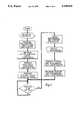
- FIG. 11is a high level flow chart of an image fusion controlling program in accordance with the present invention.
- FIG. 1there is shown a block diagram of an image fusion circuit in accordance with the present invention.
- the systemprovides a fused video output and receives two different digital video inputs from the sensor field.
- the sensor fieldsare aligned and are either identical or subsets of one another.
- the systemaccepts digitized pixel aligned data from each sensor at the feature/background separation circuit which separates the video signals from input into features and backgrounds.
- the backgroundis selected or generated on a global basis.
- the feature/background separation circuitgenerates the features from each of the first and second inputs on separate lines to a local area feature selection circuit and also generates the background from each of the first and second digital video inputs on separate lines to a global background selection circuit.
- the feature selection circuitselects the appropriate, principal or best feature at each pixel, on a pixel by pixel basis, such as the feature with the greatest magnitude, and sends a single composite feature video stream signal indicative thereof to the feature/background merge circuit.
- the background selection circuitselects the background on a global basis rather than on a pixel by pixel basis.
- the selected backgroundmay be either of the first video background or the second video background or an average of the two. Under most circumstances, the average background is selected. In certain applications where one of the background signals contains little useful information, the other background signal may be selected.
- the selection processcan be automated by using the background statistics as criteria for selecting the desired output. The statistics utilized would be the standard deviation of the grey level histogram or the peak-to-peak values of the background signals. Both the peak-to-peak statistic and the standard deviation of the grey level histogram are indicative of the variations seen in the background.
- the background selection circuitrysends a single composite video signal indicative thereof to the feature background merge circuit. These composite feature video stream signals and composite background video stream signals are the merged into a final composite fused video output by the feature/background merge circuit.
- the ratio of features to backgroundcan be controlled by frequency content specification.
- Frequency content specificationis a means whereby the ratio of background to features (or low spatial frequencies to high spatial frequencies) in the resultant image is continuously monitored and adjusted to maintain optimum image quality.
- imaged scenescontain much higher dynamic range than can be displayed on a CRT or other type of video display device.
- Much of the dynamic rangeis due to wide variations in the low frequency components of the scene which typically do not contain information of interest.
- the effecthas come to be known as the "sky-wedge" effect due to the tremendous thermal difference between sky and ground relative to the small thermal variations in the detail of interest.
- FIG. 10illustrates this effect and how frequency content specification processing can be utilized to reduce the contribution of the low frequency components and increase the contribution of the feature or high frequency components in a signal.
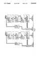
- FIG. 2there is shown a block diagram of the feature/background separation circuit of FIG. 1.
- the feature/background separation circuitis actually two identical circuits, one circuit to accept a first of the digital video inputs and provide therefrom a first video background and a first video features signal and the other circuit to accept a second of the digital video inputs and provide therefrom a second video background and a second video features signal.
- the separation criteriaare based upon the two dimensional spatial frequency spectra. Since the two circuits are identical, only one will be described, it being understood that each of the circuits operates identically.
- the backgroundis determined by storing the input digital video signal in a line storage or video shift register and then convolving the video signal with a two dimensional low-pass filter or finite impulse response (FIR) filter.
- the two dimensional convolutionimplements the equation: ##EQU1## where: y(n,m) is the filtered output pixel
- x(n-1,m-k)are the neighborhood pixels
- hi,kare the FIR filter coefficients.
- Two dimensional FIR filterswhich implement a 7 ⁇ 7 filtering function provide sufficient frequency resolution for adequate image fusion.
- These filterscan be implemented with off-the-shelf devices such as the LSI Logic L64240 or the INMOS IMSA110.
- the L64240requires an external video shift register while the IMSA110 requires multiple devices to be cascaded.
- These off-the-shelf devicescan typically operate at about 20 MHz maximum data rates.
- DSPdigital signal processing
- ASICapplication specific integrated circuit
- a typical 2-dimensional low-pass frequency response curveis shown in FIG. 6. The output of the 2-dimensional filter provides the first video background signal.
- the background informationis obtained by the low pass filtering operation.
- the featuresare obtained by subtracting the low frequency or video background from the original delayed or phase equalized input digital video signal.
- the delay in the phase equalize circuitis sufficient to compensate for the accumulate delay in each of the 1-dimension low pass pre-filter, if used, the decimation circuit, if used, the line storage or video shift register, the 2-dimension low-pass filter (FIR) and the 1-dimension low pass filter (interpolate) (FIR), if used.
- the input digital video signalis pre-filtered in the 1-dimension low pass pre-filter of standard type, the characteristics of which are programmed by means of appropriate coefficients in well known manner, such as, for example, using an LSI Logic L64143. Coefficients are calculated to perform a low-pass filtering function to attenuate frequency components higher than one half the equivalent sampling frequency of the decimation circuitry, if used. Pre-filtering is required only if decimation is utilized. The prefiltering prevents spectral aliasing from occurring if the signal is decimated. The output of this filter is decimated in the decimation circuit which is a standard circuit for passing therethrough every Nth sample applied thereto, the value of N being predetermined.
- the output of the decimation circuitis then passed to the line storage circuit which is a standard shift register such as, for example, an LSI Logic L64211.
- the output of the 2-dimension low-pass filteris passed to a 1-dimension low-pass filter from which the video background signal is then provided which can be the same as the previously discussed 1-dimension low-pass filter but with different coefficients.
- This filterperforms linear interpolation to calculate the sample points between the output samples of the 2-dimensional low-pass filter, which are decimated, such that the sample rate now matches the delayed phase equalized video.
- aliasingis a common effect seen in sampled data systems which occurs when the sampled signal contains frequency components greater than one half the sample frequency. The result of aliasing is that the components of the signal greater than half the sample frequency appear as lower frequency signals in the sampled signal and the original signal cannot be adequately reproduced.) that would result when the signal is decimated.
- One dimensional pre-filtering, decimation and interpolationprovides sufficient data rate reduction for the two dimensional FIR filter. For example, if decimation by four is applied, pixel rates as high as 80 MHz can be processed by the L64240 device.
- the feature component of the input digital video signalis derived by subtracting the video background from the delayed input digital video signal in the subtract circuit by standard twos complement addition.
- the delay provided by the phase equalize or delay circuitwhich is a standard digital delay line, compensates for the two dimensional phase shift and any other delay that occurs as a result of the filtering process.
- the resultant featuresrepresent the higher frequency components of the video which are not contained in the background.
- FIG. 8illustrates the two dimensional frequency response. A one dimensional "slice" of the resultant feature spatial frequency content is shown in FIG. 9.
- the feature with the greatest magnitude, whether positive or negative,is selected at each pixel location as shown in the feature selection circuit in FIG. 3 where two identical circuits receive and process the feature signals. This is accomplished by taking the absolute value in a standard absolute value circuit of each feature pixel from FIG. 2 and providing a weighted gain thereof for one of the input signals relative to the other input signal, if desired, in a gain circuit for each of the first and second video feature digital signals. The outputs of the gain circuits are compared in a compare circuit of standard type which provides an output of the input signal thereto of greater magnitude. Different weighting would be employed if, for example, it were known that one source was noisier than the other.
- the outputs of the gain circuitsare compared in a compare circuit of standard type which provides an output of the input signal thereto of greater magnitude through a select circuit. Also, the inputs to the absolute value circuits are each fed to the select circuit via a separate delay circuit. The delay circuits are employed to synchronize the features with the comparison results. It follows that, based upon the output of the compare circuit, the select circuit merely permits either the delayed first video features or the delayed second video features to be output therefrom a the selected features. This output is a signed composite feature image with both positive and negative features.
- the background selection circuitis shown in FIG. 4.
- the background selectionoccurs on a global basis rather than a pixel-by-pixel basis. This is, the parameters controlling the selection process are only updated on a video frame basis.
- the output backgroundcan be either of the video 1 background, video 2 background from FIG. 2 or an average of the two. Continuously selecting the average of the two backgrounds is adequate for many applications. However, if one sensor contains little information or is "washed out", the other background can be selected.
- the selection processcan also be programmed to occur automatically under processor control.
- the peak-to-peak and/or grey level histograms of each backgroundare sampled during the video frame and are used as criteria to select the background or combinations of backgrounds to be output on the next video frame.
- the peak-to-peak measurements of each of the backgroundsis used as the selection criterion:
- the selection processis governed by the following:
- Peak-to-peak circuitsare standard and are defined in many digital logic textbooks. These circuits store both the highest and lowest values occurring in a data stream over a given period of time or until reset. Grey level histogram circuits are also standard in the field of image processing and are described in many image processing textbooks. They are also available as single parts such as the LSI Logic L64250. These histogram circuits collect the histogram data from which the controlling program calculates the standard deviation statistic.
- the processor buscan be any generic processor which controls the selection process as well as retrieving statistical information used as selection criteria by loading each of the circuits to which it is coupled with the appropriate parameters, such as the coefficients, etc. reading the peak detectors and histograms and making decisions as to which global background should be selected.
- the input to the background select or average circuitform the processor bus determines whether that circuit will select a particular one of the input signals thereto or average the input signals thereto.
- the background output from the background select or average circuitis delayed in the delay circuit to provide proper alignment with the feature output signal of FIG. 3.
- the composite features and composite background signals from FIGS. 3 and 4are combined as shown in FIG. 5 in the feature/background merge circuit.
- the peak to peak magnitude of both the features and backgroundis continuously sampled on a frame by frame basis in a frequency content statistics circuit which measures the peak to peak value of the features and the peak to peak value of the background.
- the frequency content statistics circuitrypasses the composite features and composite background signals unchanged.
- the peak-to-peak statistics of each signalare measured during a video frame and analyzed by the controlling processor to calculate the gains to be programmed into the feature gain and background gain circuits for the next video frame.
- An offset valueis added to the result of the gain multiplication of the composite background in the background gain and offset circuit. This offset value is selected to center the resultant background signal within the available dynamic range.
- the peak-to-peak detectorsare the same as described hereinabove.
- This circuitrystores both the highest and lowest values seen on the data stream during a video frame. In the case of the features which are both positive and negative, the lowest value is taken as the most negative.
- Both the feature and background gain circuitsare constructed from standard digital multipliers which are off-the-shelf items.
- the output of the frequency content statistics circuitis applied along one line as composite features signals to a feature gain circuit and along a second line as composite background signals to a background gain circuit.
- the processorcontinually adjusts the gain of each of the feature gain and background gain circuits to maintain the optimum ratio of high and low frequency components. If no enhancements are desired, both gains are set to 1.
- the scaled features and background signalsare then added together in a signed add circuit to form the final fused digital video image signal for transmission to an external device, such as, for example, a cathode ray tube.
- the features signal to the signed add circuitcan be positive or negative whereas the background signal thereto is always positive. Therefore, if the features are negative, they subtract from the background and, if positive, they add. Therefore, the signed adder is a standard adder capable of accepting negative numbers.
- the processorof which only the bus is discussed herein, can be any standard processor capable of performing the functions ascribed thereto herein.
- An 8086 processorcan be used, for example.
- Attached hereto as FIG. 11is a flow chart which sets forth the control of the processor for use in accordance with the present invention.
- the above described method and system for fusing imagery from multiple sourcesemploys various novel concepts as applied to image fusion.
- the overall concept of feature/background separation, feature selection, background selection and feature/background mergeis novel.
- the approach in which the proportion of composite feature and background video is controlled in the resultant fused outputis also novel.
- the video sourcescan be different from the two listed herein. More than two sensor output can also be fused.
- the inventioncan be applied to a variety of video formats including interlaced, non-interlaced and horizontal and vertical raster formats.
Landscapes
- Physics & Mathematics (AREA)
- General Physics & Mathematics (AREA)
- Engineering & Computer Science (AREA)
- Theoretical Computer Science (AREA)
- Image Processing (AREA)
- Studio Circuits (AREA)
Abstract
Description
Claims (30)
Priority Applications (4)
| Application Number | Priority Date | Filing Date | Title |
|---|---|---|---|
| US07/583,980US5140416A (en) | 1990-09-18 | 1990-09-18 | System and method for fusing video imagery from multiple sources in real time |
| DE69132203TDE69132203T2 (en) | 1990-09-18 | 1991-09-17 | System and method for real-time mixing of video images from multiple sources |
| EP91308450AEP0476959B1 (en) | 1990-09-18 | 1991-09-17 | System and method for fusing video imagery from multiple sources in real time |
| JP23826591AJP3151245B2 (en) | 1990-09-18 | 1991-09-18 | System and method for synthesizing video images from multiple sources in real time |
Applications Claiming Priority (1)
| Application Number | Priority Date | Filing Date | Title |
|---|---|---|---|
| US07/583,980US5140416A (en) | 1990-09-18 | 1990-09-18 | System and method for fusing video imagery from multiple sources in real time |
Publications (1)
| Publication Number | Publication Date |
|---|---|
| US5140416Atrue US5140416A (en) | 1992-08-18 |
Family
ID=24335407
Family Applications (1)
| Application Number | Title | Priority Date | Filing Date |
|---|---|---|---|
| US07/583,980Expired - LifetimeUS5140416A (en) | 1990-09-18 | 1990-09-18 | System and method for fusing video imagery from multiple sources in real time |
Country Status (4)
| Country | Link |
|---|---|
| US (1) | US5140416A (en) |
| EP (1) | EP0476959B1 (en) |
| JP (1) | JP3151245B2 (en) |
| DE (1) | DE69132203T2 (en) |
Cited By (75)
| Publication number | Priority date | Publication date | Assignee | Title |
|---|---|---|---|---|
| WO1993013404A1 (en)* | 1991-12-23 | 1993-07-08 | Electric Power Research Institute, Inc. | Video fluorescence monitor for determination of pcb or pcb mineral oil spill outline |
| WO1993023823A1 (en)* | 1992-05-15 | 1993-11-25 | David Sarnoff Research Center, Inc. | Method for fusing images and apparatus therefor |
| US5274236A (en)* | 1992-12-16 | 1993-12-28 | Westinghouse Electric Corp. | Method and apparatus for registering two images from different sensors |
| US5313567A (en)* | 1991-06-13 | 1994-05-17 | At&T Bell Laboratories | Arrangement for determining and displaying volumetric data in an imaging system |
| US5387937A (en)* | 1992-02-13 | 1995-02-07 | Sony United Kingdom Limited | Motion compensation for color video signals |
| US5404013A (en)* | 1993-02-25 | 1995-04-04 | Fujitsu Limited | Infrared imaging system having an automatic focusing control |
| US5408274A (en)* | 1993-03-11 | 1995-04-18 | The Regents Of The University Of California | Method and apparatus for compositing compressed video data |
| US5479526A (en)* | 1993-03-23 | 1995-12-26 | Martin Marietta | Pixel designator for small objects |
| US5615282A (en)* | 1990-02-05 | 1997-03-25 | Scitex Corporation Ltd. | Apparatus and techniques for processing of data such as color images |
| US5629866A (en)* | 1994-03-18 | 1997-05-13 | U.S. Philips Corporation | Audio-visual presentation system |
| US5644386A (en)* | 1995-01-11 | 1997-07-01 | Loral Vought Systems Corp. | Visual recognition system for LADAR sensors |
| US5657402A (en)* | 1991-11-01 | 1997-08-12 | Massachusetts Institute Of Technology | Method of creating a high resolution still image using a plurality of images and apparatus for practice of the method |
| US5774589A (en)* | 1995-02-14 | 1998-06-30 | Fujitsu Limited | Image processing system |
| WO1998040711A1 (en)* | 1997-03-13 | 1998-09-17 | Accurate Automation Corporation | Sensor fusion apparatus and method |
| US5953462A (en)* | 1989-01-31 | 1999-09-14 | Yoshiro Yamada | Method and apparatus for processing image |
| US5991444A (en)* | 1994-11-14 | 1999-11-23 | Sarnoff Corporation | Method and apparatus for performing mosaic based image compression |
| US6007052A (en)* | 1997-06-21 | 1999-12-28 | Raytheon Company | System and method for local area image processing |
| US6078701A (en)* | 1997-08-01 | 2000-06-20 | Sarnoff Corporation | Method and apparatus for performing local to global multiframe alignment to construct mosaic images |
| US6084590A (en)* | 1997-04-07 | 2000-07-04 | Synapix, Inc. | Media production with correlation of image stream and abstract objects in a three-dimensional virtual stage |
| US6124864A (en)* | 1997-04-07 | 2000-09-26 | Synapix, Inc. | Adaptive modeling and segmentation of visual image streams |
| US6128001A (en)* | 1997-04-04 | 2000-10-03 | Avid Technology, Inc. | Methods and apparatus for changing a color of an image |
| US6137919A (en)* | 1997-04-04 | 2000-10-24 | Avid Technology, Inc. | Apparatus and methods for feathering a composite image |
| US6160907A (en)* | 1997-04-07 | 2000-12-12 | Synapix, Inc. | Iterative three-dimensional process for creating finished media content |
| WO2000054217A3 (en)* | 1999-03-05 | 2001-04-26 | Flir Systems | Enhanced vision system sensitive to infrared radiation |
| US6233736B1 (en) | 1996-02-08 | 2001-05-15 | Media Online Services, Inc. | Media online service access system and method |
| US6249285B1 (en) | 1998-04-06 | 2001-06-19 | Synapix, Inc. | Computer assisted mark-up and parameterization for scene analysis |
| US6266053B1 (en) | 1998-04-03 | 2001-07-24 | Synapix, Inc. | Time inheritance scene graph for representation of media content |
| US6269195B1 (en) | 1997-04-04 | 2001-07-31 | Avid Technology, Inc. | Apparatus and methods for selectively feathering a composite image |
| US6297825B1 (en) | 1998-04-06 | 2001-10-02 | Synapix, Inc. | Temporal smoothing of scene analysis data for image sequence generation |
| US6301382B1 (en)* | 1996-06-07 | 2001-10-09 | Microsoft Corporation | Extracting a matte of a foreground object from multiple backgrounds by triangulation |
| US6351557B1 (en) | 1998-04-03 | 2002-02-26 | Avid Technology, Inc. | Method and apparatus for color manipulation |
| US6356294B1 (en)* | 1998-08-11 | 2002-03-12 | 8×8, Inc. | Multi-point communication arrangement and method |
| US6417891B1 (en) | 1999-04-16 | 2002-07-09 | Avid Technology, Inc. | Color modification on a digital nonlinear editing system |
| US6417797B1 (en) | 1998-07-14 | 2002-07-09 | Cirrus Logic, Inc. | System for A multi-purpose portable imaging device and methods for using same |
| US6456340B1 (en) | 1998-08-12 | 2002-09-24 | Pixonics, Llc | Apparatus and method for performing image transforms in a digital display system |
| US6477271B1 (en) | 2000-04-07 | 2002-11-05 | Avid Technology, Inc. | Secondary color modification of a digital image |
| US20030071824A1 (en)* | 1999-04-16 | 2003-04-17 | Robert Gonsalves | Multi-tone representation of a digital image on a digital nonlinear editing system |
| US6571255B1 (en) | 1999-04-16 | 2003-05-27 | Robert Gonsalves | Modification of media with common attributes on a digital nonlinear editing system |
| US20040086021A1 (en)* | 2002-11-01 | 2004-05-06 | Litwin Robert Zachary | Infrared temperature sensors for solar panel |
| US6766054B1 (en)* | 2000-08-14 | 2004-07-20 | International Business Machines Corporation | Segmentation of an object from a background in digital photography |
| US20040240729A1 (en)* | 2000-04-07 | 2004-12-02 | Cooper Brian C. | Secondary color modification of a digital image |
| US6847373B1 (en) | 1999-04-16 | 2005-01-25 | Avid Technology, Inc. | Natural color matching in a video editing system |
| US20050190990A1 (en)* | 2004-01-27 | 2005-09-01 | Burt Peter J. | Method and apparatus for combining a plurality of images |
| US6975779B1 (en)* | 1998-09-28 | 2005-12-13 | Infineon Technologies Ag | Method for modifying the image size of video images |
| EP1287684A4 (en)* | 2000-04-27 | 2006-07-12 | Litton Systems Inc | METHOD AND SYSTEM FOR IMAGE FUSION |
| US7099041B1 (en)* | 1999-03-02 | 2006-08-29 | Seiko Epson Corporation | Image data background determining apparatus image data background determining method, and medium recording thereon image data background determination control program |
| US20060249679A1 (en)* | 2004-12-03 | 2006-11-09 | Johnson Kirk R | Visible light and ir combined image camera |
| US20070065012A1 (en)* | 2005-09-16 | 2007-03-22 | Seiko Epson Corporation | Image processing apparatus, image processing method, and program product |
| US20080099678A1 (en)* | 2004-12-03 | 2008-05-01 | Johnson Kirk R | Camera with visible light and infrared image blending |
| US20080243636A1 (en)* | 2007-03-27 | 2008-10-02 | Texas Instruments Incorporated | Selective Product Placement Using Image Processing Techniques |
| US20090050806A1 (en)* | 2004-12-03 | 2009-02-26 | Fluke Corporation | Visible light and ir combined image camera with a laser pointer |
| US20090066841A1 (en)* | 2007-09-12 | 2009-03-12 | Quanta Computer Inc. | Image processing method and computer readable medium |
| US20110262053A1 (en)* | 2010-04-23 | 2011-10-27 | Flir Systems Ab | Infrared resolution and contrast enhancement with fusion |
| WO2011135060A1 (en) | 2010-04-29 | 2011-11-03 | Norsk Institutt For Luftforskning | System and method for detecting adverse atmospheric conditions ahead of an aircraft |
| AU2011100797B4 (en)* | 2010-04-29 | 2011-11-24 | Nicarnica Aviation As | System and method for detecting adverse atmospheric conditions ahead of an aircraft |
| US8139863B1 (en)* | 2008-04-25 | 2012-03-20 | Hsu Shin-Yi | System for capturing, characterizing and visualizing lidar and generic image data |
| US20140104415A1 (en)* | 2009-06-03 | 2014-04-17 | Flir Systems, Inc. | Measurement device for electrical installations and related methods |
| US8830360B1 (en) | 2010-08-25 | 2014-09-09 | Sri International | Method and apparatus for optimizing image quality based on scene content |
| US8958654B1 (en)* | 2001-04-25 | 2015-02-17 | Lockheed Martin Corporation | Method and apparatus for enhancing three-dimensional imagery data |
| US8970665B2 (en) | 2011-05-25 | 2015-03-03 | Microsoft Corporation | Orientation-based generation of panoramic fields |
| US20150147046A1 (en)* | 2012-06-01 | 2015-05-28 | Alcatel Lucent | Method and apparatus for mixing a first video signal and a second video signal |
| US9171361B2 (en) | 2010-04-23 | 2015-10-27 | Flir Systems Ab | Infrared resolution and contrast enhancement with fusion |
| US9706138B2 (en) | 2010-04-23 | 2017-07-11 | Flir Systems, Inc. | Hybrid infrared sensor array having heterogeneous infrared sensors |
| US9723229B2 (en) | 2010-08-27 | 2017-08-01 | Milwaukee Electric Tool Corporation | Thermal detection systems, methods, and devices |
| US9843743B2 (en) | 2009-06-03 | 2017-12-12 | Flir Systems, Inc. | Infant monitoring systems and methods using thermal imaging |
| US9848134B2 (en) | 2010-04-23 | 2017-12-19 | Flir Systems, Inc. | Infrared imager with integrated metal layers |
| US9883084B2 (en) | 2011-03-15 | 2018-01-30 | Milwaukee Electric Tool Corporation | Thermal imager |
| US10044946B2 (en) | 2009-06-03 | 2018-08-07 | Flir Systems Ab | Facilitating analysis and interpretation of associated visible light and infrared (IR) image information |
| US10539502B2 (en) | 2015-04-27 | 2020-01-21 | Flir Systems, Inc. | Moisture measurement device with thermal imaging capabilities and related methods |
| US10794769B2 (en) | 2012-08-02 | 2020-10-06 | Milwaukee Electric Tool Corporation | Thermal detection systems, methods, and devices |
| US10846924B2 (en) | 2018-04-04 | 2020-11-24 | Flir Detection, Inc. | Threat source mapping systems and methods |
| US11505292B2 (en) | 2014-12-31 | 2022-11-22 | FLIR Belgium BVBA | Perimeter ranging sensor systems and methods |
| US12084155B2 (en) | 2017-06-16 | 2024-09-10 | FLIR Belgium BVBA | Assisted docking graphical user interface systems and methods |
| US12117832B2 (en) | 2018-10-31 | 2024-10-15 | FLIR Belgium BVBA | Dynamic proximity alert systems and methods |
| US12205473B2 (en) | 2017-06-16 | 2025-01-21 | FLIR Belgium BVBA | Collision avoidance systems and methods |
Families Citing this family (10)
| Publication number | Priority date | Publication date | Assignee | Title |
|---|---|---|---|---|
| US6061068A (en)* | 1998-06-30 | 2000-05-09 | Raytheon Company | Method and apparatus for providing synthetic vision using reality updated virtual image |
| WO1999001845A1 (en)* | 1997-07-02 | 1999-01-14 | Raytheon Ti Systems, Inc. | Method and apparatus for providing vision using virtual image |
| US6795590B1 (en)* | 2000-09-22 | 2004-09-21 | Hrl Laboratories, Llc | SAR and FLIR image registration method |
| DE10218175B4 (en)* | 2002-04-24 | 2011-10-27 | Bayerische Motoren Werke Aktiengesellschaft | Method and device for visualizing the environment of a vehicle with a driving-dependent fusion of an infrared and a visual image |
| DE10227171B4 (en)* | 2002-06-18 | 2019-09-26 | Bayerische Motoren Werke Aktiengesellschaft | Method and device for visualizing the environment of a vehicle with distance-dependent fusion of an infrared and a visual image |
| US7834905B2 (en) | 2002-06-18 | 2010-11-16 | Bayerische Motoren Werke Aktiengesellschaft | Method and system for visualizing the environment of a vehicle with a distance-dependent merging of an infrared and a visual image |
| DE10304703B4 (en)* | 2003-02-06 | 2023-03-16 | Bayerische Motoren Werke Aktiengesellschaft | Method and device for visualizing the environment of a vehicle with environment-dependent fusion of an infrared and a visual image |
| DE102005042987A1 (en)* | 2005-09-09 | 2007-03-22 | Hella Kgaa Hueck & Co. | Transmission of information in the image signal of a camera system |
| WO2008018042A2 (en)* | 2006-08-11 | 2008-02-14 | Koninklijke Philips Electronics N.V. | Content augmentation for personal recordings |
| JP5514538B2 (en) | 2009-12-28 | 2014-06-04 | シャープ株式会社 | Information display system and communication body and mobile phone used in the information display system |
Citations (12)
| Publication number | Priority date | Publication date | Assignee | Title |
|---|---|---|---|---|
| US4183013A (en)* | 1976-11-29 | 1980-01-08 | Coulter Electronics, Inc. | System for extracting shape features from an image |
| US4538182A (en)* | 1981-05-11 | 1985-08-27 | Canon Kabushiki Kaisha | Image processing apparatus |
| US4647965A (en)* | 1983-11-02 | 1987-03-03 | Imsand Donald J | Picture processing system for three dimensional movies and video systems |
| US4672438A (en)* | 1985-06-28 | 1987-06-09 | Her Majesty The Queen In Right Of Canada | Tracking simulator |
| EP0235902A1 (en)* | 1986-01-23 | 1987-09-09 | Crosfield Electronics Limited | Digital image processing |
| US4723159A (en)* | 1983-11-02 | 1988-02-02 | Imsand Donald J | Three dimensional television and video systems |
| US4819064A (en)* | 1987-11-25 | 1989-04-04 | The United States Of America As Represented By The Administrator Of The National Aeronautics And Space Administration | Television monitor field shifter and an opto-electronic method for obtaining a stereo image of optimal depth resolution and reduced depth distortion on a single screen |
| US4862257A (en)* | 1988-07-07 | 1989-08-29 | Kaman Aerospace Corporation | Imaging lidar system |
| US4905081A (en)* | 1986-11-06 | 1990-02-27 | British Broadcasting Corporation | Method and apparatus for transmitting and receiving 3D video pictures |
| US4967276A (en)* | 1988-05-24 | 1990-10-30 | Fujitsu Limited | Video signal mixing device for infrared/visible integrated imaging |
| US5005083A (en)* | 1988-05-19 | 1991-04-02 | Siemens Aktiengesellschaft | FLIR system with two optical channels for observing a wide and a narrow field of view |
| US5065442A (en)* | 1989-05-08 | 1991-11-12 | Canon Kabushiki Kaisha | Character recognition apparatus determining whether read data is a character line |
Family Cites Families (2)
| Publication number | Priority date | Publication date | Assignee | Title |
|---|---|---|---|---|
| FR2545349B1 (en)* | 1983-05-04 | 1986-09-26 | Duret Francois | PROCESS FOR INPUT OF THE FORM OF HUMAN ORGANS OR PATHOLOGICAL ABNORMALITIES AND DEVICE FOR IMPLEMENTING SAME |
| DE3905591C2 (en)* | 1989-02-23 | 1997-08-28 | Rheinmetall Ind Ag | Device for obtaining high-contrast images |
- 1990
- 1990-09-18USUS07/583,980patent/US5140416A/ennot_activeExpired - Lifetime
- 1991
- 1991-09-17DEDE69132203Tpatent/DE69132203T2/ennot_activeExpired - Lifetime
- 1991-09-17EPEP91308450Apatent/EP0476959B1/ennot_activeExpired - Lifetime
- 1991-09-18JPJP23826591Apatent/JP3151245B2/ennot_activeExpired - Lifetime
Patent Citations (12)
| Publication number | Priority date | Publication date | Assignee | Title |
|---|---|---|---|---|
| US4183013A (en)* | 1976-11-29 | 1980-01-08 | Coulter Electronics, Inc. | System for extracting shape features from an image |
| US4538182A (en)* | 1981-05-11 | 1985-08-27 | Canon Kabushiki Kaisha | Image processing apparatus |
| US4647965A (en)* | 1983-11-02 | 1987-03-03 | Imsand Donald J | Picture processing system for three dimensional movies and video systems |
| US4723159A (en)* | 1983-11-02 | 1988-02-02 | Imsand Donald J | Three dimensional television and video systems |
| US4672438A (en)* | 1985-06-28 | 1987-06-09 | Her Majesty The Queen In Right Of Canada | Tracking simulator |
| EP0235902A1 (en)* | 1986-01-23 | 1987-09-09 | Crosfield Electronics Limited | Digital image processing |
| US4905081A (en)* | 1986-11-06 | 1990-02-27 | British Broadcasting Corporation | Method and apparatus for transmitting and receiving 3D video pictures |
| US4819064A (en)* | 1987-11-25 | 1989-04-04 | The United States Of America As Represented By The Administrator Of The National Aeronautics And Space Administration | Television monitor field shifter and an opto-electronic method for obtaining a stereo image of optimal depth resolution and reduced depth distortion on a single screen |
| US5005083A (en)* | 1988-05-19 | 1991-04-02 | Siemens Aktiengesellschaft | FLIR system with two optical channels for observing a wide and a narrow field of view |
| US4967276A (en)* | 1988-05-24 | 1990-10-30 | Fujitsu Limited | Video signal mixing device for infrared/visible integrated imaging |
| US4862257A (en)* | 1988-07-07 | 1989-08-29 | Kaman Aerospace Corporation | Imaging lidar system |
| US5065442A (en)* | 1989-05-08 | 1991-11-12 | Canon Kabushiki Kaisha | Character recognition apparatus determining whether read data is a character line |
Cited By (122)
| Publication number | Priority date | Publication date | Assignee | Title |
|---|---|---|---|---|
| US5953462A (en)* | 1989-01-31 | 1999-09-14 | Yoshiro Yamada | Method and apparatus for processing image |
| US5615282A (en)* | 1990-02-05 | 1997-03-25 | Scitex Corporation Ltd. | Apparatus and techniques for processing of data such as color images |
| US5313567A (en)* | 1991-06-13 | 1994-05-17 | At&T Bell Laboratories | Arrangement for determining and displaying volumetric data in an imaging system |
| US5920657A (en)* | 1991-11-01 | 1999-07-06 | Massachusetts Institute Of Technology | Method of creating a high resolution still image using a plurality of images and apparatus for practice of the method |
| US5657402A (en)* | 1991-11-01 | 1997-08-12 | Massachusetts Institute Of Technology | Method of creating a high resolution still image using a plurality of images and apparatus for practice of the method |
| US5281826A (en)* | 1991-12-23 | 1994-01-25 | Electric Power Research Institute, Inc. | Video fluorescence monitor for determination of spill outlines |
| WO1993013404A1 (en)* | 1991-12-23 | 1993-07-08 | Electric Power Research Institute, Inc. | Video fluorescence monitor for determination of pcb or pcb mineral oil spill outline |
| US5387937A (en)* | 1992-02-13 | 1995-02-07 | Sony United Kingdom Limited | Motion compensation for color video signals |
| US5325449A (en)* | 1992-05-15 | 1994-06-28 | David Sarnoff Research Center, Inc. | Method for fusing images and apparatus therefor |
| US5488674A (en)* | 1992-05-15 | 1996-01-30 | David Sarnoff Research Center, Inc. | Method for fusing images and apparatus therefor |
| WO1993023823A1 (en)* | 1992-05-15 | 1993-11-25 | David Sarnoff Research Center, Inc. | Method for fusing images and apparatus therefor |
| US5274236A (en)* | 1992-12-16 | 1993-12-28 | Westinghouse Electric Corp. | Method and apparatus for registering two images from different sensors |
| US5404013A (en)* | 1993-02-25 | 1995-04-04 | Fujitsu Limited | Infrared imaging system having an automatic focusing control |
| US5408274A (en)* | 1993-03-11 | 1995-04-18 | The Regents Of The University Of California | Method and apparatus for compositing compressed video data |
| US5479526A (en)* | 1993-03-23 | 1995-12-26 | Martin Marietta | Pixel designator for small objects |
| US5629866A (en)* | 1994-03-18 | 1997-05-13 | U.S. Philips Corporation | Audio-visual presentation system |
| US5991444A (en)* | 1994-11-14 | 1999-11-23 | Sarnoff Corporation | Method and apparatus for performing mosaic based image compression |
| US6393163B1 (en) | 1994-11-14 | 2002-05-21 | Sarnoff Corporation | Mosaic based image processing system |
| US5999662A (en)* | 1994-11-14 | 1999-12-07 | Sarnoff Corporation | System for automatically aligning images to form a mosaic image |
| US5644386A (en)* | 1995-01-11 | 1997-07-01 | Loral Vought Systems Corp. | Visual recognition system for LADAR sensors |
| US5774589A (en)* | 1995-02-14 | 1998-06-30 | Fujitsu Limited | Image processing system |
| US6233736B1 (en) | 1996-02-08 | 2001-05-15 | Media Online Services, Inc. | Media online service access system and method |
| US6301382B1 (en)* | 1996-06-07 | 2001-10-09 | Microsoft Corporation | Extracting a matte of a foreground object from multiple backgrounds by triangulation |
| WO1998040711A1 (en)* | 1997-03-13 | 1998-09-17 | Accurate Automation Corporation | Sensor fusion apparatus and method |
| US5850625A (en)* | 1997-03-13 | 1998-12-15 | Accurate Automation Corporation | Sensor fusion apparatus and method |
| US6269195B1 (en) | 1997-04-04 | 2001-07-31 | Avid Technology, Inc. | Apparatus and methods for selectively feathering a composite image |
| US6128001A (en)* | 1997-04-04 | 2000-10-03 | Avid Technology, Inc. | Methods and apparatus for changing a color of an image |
| US6137919A (en)* | 1997-04-04 | 2000-10-24 | Avid Technology, Inc. | Apparatus and methods for feathering a composite image |
| US6124864A (en)* | 1997-04-07 | 2000-09-26 | Synapix, Inc. | Adaptive modeling and segmentation of visual image streams |
| US6160907A (en)* | 1997-04-07 | 2000-12-12 | Synapix, Inc. | Iterative three-dimensional process for creating finished media content |
| US6084590A (en)* | 1997-04-07 | 2000-07-04 | Synapix, Inc. | Media production with correlation of image stream and abstract objects in a three-dimensional virtual stage |
| US6007052A (en)* | 1997-06-21 | 1999-12-28 | Raytheon Company | System and method for local area image processing |
| US6078701A (en)* | 1997-08-01 | 2000-06-20 | Sarnoff Corporation | Method and apparatus for performing local to global multiframe alignment to construct mosaic images |
| US6351557B1 (en) | 1998-04-03 | 2002-02-26 | Avid Technology, Inc. | Method and apparatus for color manipulation |
| US6266053B1 (en) | 1998-04-03 | 2001-07-24 | Synapix, Inc. | Time inheritance scene graph for representation of media content |
| US6297825B1 (en) | 1998-04-06 | 2001-10-02 | Synapix, Inc. | Temporal smoothing of scene analysis data for image sequence generation |
| US6249285B1 (en) | 1998-04-06 | 2001-06-19 | Synapix, Inc. | Computer assisted mark-up and parameterization for scene analysis |
| US6417797B1 (en) | 1998-07-14 | 2002-07-09 | Cirrus Logic, Inc. | System for A multi-purpose portable imaging device and methods for using same |
| US6356294B1 (en)* | 1998-08-11 | 2002-03-12 | 8×8, Inc. | Multi-point communication arrangement and method |
| US6456340B1 (en) | 1998-08-12 | 2002-09-24 | Pixonics, Llc | Apparatus and method for performing image transforms in a digital display system |
| US6975779B1 (en)* | 1998-09-28 | 2005-12-13 | Infineon Technologies Ag | Method for modifying the image size of video images |
| US7099041B1 (en)* | 1999-03-02 | 2006-08-29 | Seiko Epson Corporation | Image data background determining apparatus image data background determining method, and medium recording thereon image data background determination control program |
| WO2000054217A3 (en)* | 1999-03-05 | 2001-04-26 | Flir Systems | Enhanced vision system sensitive to infrared radiation |
| US6806469B2 (en) | 1999-03-05 | 2004-10-19 | Flir Systems, Inc. | Enhanced vision system sensitive to infrared radiation |
| US6232602B1 (en)* | 1999-03-05 | 2001-05-15 | Flir Systems, Inc. | Enhanced vision system sensitive to infrared radiation |
| US7102130B2 (en) | 1999-03-05 | 2006-09-05 | Flir Systems, Inc. | Enhanced vision system sensitive to infrared radiation |
| US6373055B1 (en)* | 1999-03-05 | 2002-04-16 | Flir Systems, Inc. | Enhanced vision system sensitive to infrared radiation |
| US20070075244A1 (en)* | 1999-03-05 | 2007-04-05 | Kerr Jones R | Enhanced vision system sensitive to infrared radiation |
| US7655908B2 (en) | 1999-03-05 | 2010-02-02 | Flir Systems, Inc. | Enhanced vision system sensitive to infrared radiation |
| US20050161603A1 (en)* | 1999-03-05 | 2005-07-28 | Kerr Jones R. | Enhanced vision system sensitive to infrared radiation |
| US20100207026A1 (en)* | 1999-03-05 | 2010-08-19 | Janes Richard Kerr | Enhanced vision system sensitive to infrared radiation |
| US7973800B2 (en) | 1999-04-16 | 2011-07-05 | Avid Technology, Inc. | Source color modification on a digital nonlinear editing system |
| US6847373B1 (en) | 1999-04-16 | 2005-01-25 | Avid Technology, Inc. | Natural color matching in a video editing system |
| US6417891B1 (en) | 1999-04-16 | 2002-07-09 | Avid Technology, Inc. | Color modification on a digital nonlinear editing system |
| US6933948B2 (en) | 1999-04-16 | 2005-08-23 | Avid Technology, Inc. | Multi-tone representation of a digital image on a digital nonlinear editing system |
| US6571255B1 (en) | 1999-04-16 | 2003-05-27 | Robert Gonsalves | Modification of media with common attributes on a digital nonlinear editing system |
| US6552731B1 (en) | 1999-04-16 | 2003-04-22 | Avid Technology, Inc. | Multi-tone representation of a digital image on a digital nonlinear editing system |
| US20030071824A1 (en)* | 1999-04-16 | 2003-04-17 | Robert Gonsalves | Multi-tone representation of a digital image on a digital nonlinear editing system |
| US7081900B2 (en) | 1999-04-16 | 2006-07-25 | Avid Technology, Inc. | Graphical user interface for color correction |
| US20040240729A1 (en)* | 2000-04-07 | 2004-12-02 | Cooper Brian C. | Secondary color modification of a digital image |
| US6763134B2 (en) | 2000-04-07 | 2004-07-13 | Avid Technology, Inc. | Secondary color modification of a digital image |
| US6928187B2 (en) | 2000-04-07 | 2005-08-09 | Avid Technology, Inc. | Secondary color modification of a digital image |
| US6477271B1 (en) | 2000-04-07 | 2002-11-05 | Avid Technology, Inc. | Secondary color modification of a digital image |
| EP1287684A4 (en)* | 2000-04-27 | 2006-07-12 | Litton Systems Inc | METHOD AND SYSTEM FOR IMAGE FUSION |
| US6766054B1 (en)* | 2000-08-14 | 2004-07-20 | International Business Machines Corporation | Segmentation of an object from a background in digital photography |
| US8958654B1 (en)* | 2001-04-25 | 2015-02-17 | Lockheed Martin Corporation | Method and apparatus for enhancing three-dimensional imagery data |
| US6926440B2 (en)* | 2002-11-01 | 2005-08-09 | The Boeing Company | Infrared temperature sensors for solar panel |
| US20040086021A1 (en)* | 2002-11-01 | 2004-05-06 | Litwin Robert Zachary | Infrared temperature sensors for solar panel |
| WO2005072431A3 (en)* | 2004-01-27 | 2006-03-16 | Sarnoff Corp | A method and apparatus for combining a plurality of images |
| US20050190990A1 (en)* | 2004-01-27 | 2005-09-01 | Burt Peter J. | Method and apparatus for combining a plurality of images |
| US20090050806A1 (en)* | 2004-12-03 | 2009-02-26 | Fluke Corporation | Visible light and ir combined image camera with a laser pointer |
| US11032492B2 (en) | 2004-12-03 | 2021-06-08 | Fluke Corporation | Visible light and IR combined image camera |
| US20060249679A1 (en)* | 2004-12-03 | 2006-11-09 | Johnson Kirk R | Visible light and ir combined image camera |
| US8531562B2 (en) | 2004-12-03 | 2013-09-10 | Fluke Corporation | Visible light and IR combined image camera with a laser pointer |
| US7535002B2 (en) | 2004-12-03 | 2009-05-19 | Fluke Corporation | Camera with visible light and infrared image blending |
| US7538326B2 (en) | 2004-12-03 | 2009-05-26 | Fluke Corporation | Visible light and IR combined image camera with a laser pointer |
| US20090302219A1 (en)* | 2004-12-03 | 2009-12-10 | Fluke Corporation | Visible light and ir combined image camera |
| US20060289772A1 (en)* | 2004-12-03 | 2006-12-28 | Johnson Kirk R | Visible light and IR combined image camera with a laser pointer |
| US20080099678A1 (en)* | 2004-12-03 | 2008-05-01 | Johnson Kirk R | Camera with visible light and infrared image blending |
| US8466422B2 (en) | 2004-12-03 | 2013-06-18 | Fluke Corporation | Visible light and IR combined image camera |
| US7994480B2 (en) | 2004-12-03 | 2011-08-09 | Fluke Corporation | Visible light and IR combined image camera |
| US9635282B2 (en) | 2004-12-03 | 2017-04-25 | Fluke Corporation | Visible light and IR combined image camera |
| US20070065012A1 (en)* | 2005-09-16 | 2007-03-22 | Seiko Epson Corporation | Image processing apparatus, image processing method, and program product |
| US7526139B2 (en)* | 2005-09-16 | 2009-04-28 | Seiko Epson Corporation | Image processing for improving character readability of characters disposed on an image |
| US20080243636A1 (en)* | 2007-03-27 | 2008-10-02 | Texas Instruments Incorporated | Selective Product Placement Using Image Processing Techniques |
| US8212929B2 (en)* | 2007-09-12 | 2012-07-03 | Quanta Computer Inc. | Image processing method and computer readable medium |
| US20090066841A1 (en)* | 2007-09-12 | 2009-03-12 | Quanta Computer Inc. | Image processing method and computer readable medium |
| US8139863B1 (en)* | 2008-04-25 | 2012-03-20 | Hsu Shin-Yi | System for capturing, characterizing and visualizing lidar and generic image data |
| US10044946B2 (en) | 2009-06-03 | 2018-08-07 | Flir Systems Ab | Facilitating analysis and interpretation of associated visible light and infrared (IR) image information |
| US9843743B2 (en) | 2009-06-03 | 2017-12-12 | Flir Systems, Inc. | Infant monitoring systems and methods using thermal imaging |
| US9716843B2 (en)* | 2009-06-03 | 2017-07-25 | Flir Systems, Inc. | Measurement device for electrical installations and related methods |
| US20140104415A1 (en)* | 2009-06-03 | 2014-04-17 | Flir Systems, Inc. | Measurement device for electrical installations and related methods |
| US8565547B2 (en)* | 2010-04-23 | 2013-10-22 | Flir Systems Ab | Infrared resolution and contrast enhancement with fusion |
| US9848134B2 (en) | 2010-04-23 | 2017-12-19 | Flir Systems, Inc. | Infrared imager with integrated metal layers |
| US8520970B2 (en)* | 2010-04-23 | 2013-08-27 | Flir Systems Ab | Infrared resolution and contrast enhancement with fusion |
| US11514563B2 (en) | 2010-04-23 | 2022-11-29 | Flir Systems Ab | Infrared resolution and contrast enhancement with fusion |
| US20110262053A1 (en)* | 2010-04-23 | 2011-10-27 | Flir Systems Ab | Infrared resolution and contrast enhancement with fusion |
| US9171361B2 (en) | 2010-04-23 | 2015-10-27 | Flir Systems Ab | Infrared resolution and contrast enhancement with fusion |
| US9471970B2 (en) | 2010-04-23 | 2016-10-18 | Flir Systems Ab | Infrared resolution and contrast enhancement with fusion |
| US10249032B2 (en) | 2010-04-23 | 2019-04-02 | Flir Systems Ab | Infrared resolution and contrast enhancement with fusion |
| US9706138B2 (en) | 2010-04-23 | 2017-07-11 | Flir Systems, Inc. | Hybrid infrared sensor array having heterogeneous infrared sensors |
| US10110833B2 (en) | 2010-04-23 | 2018-10-23 | Flir Systems, Inc. | Hybrid infrared sensor array having heterogeneous infrared sensors |
| US20110261207A1 (en)* | 2010-04-23 | 2011-10-27 | Flir Systems Ab | Infrared resolution and contrast enhancement with fusion |
| US10063794B2 (en) | 2010-04-29 | 2018-08-28 | Nicarnica Aviation As | System and method for detecting adverse atmospheric conditions ahead of an aircraft |
| AU2011100797B4 (en)* | 2010-04-29 | 2011-11-24 | Nicarnica Aviation As | System and method for detecting adverse atmospheric conditions ahead of an aircraft |
| DE212011100091U1 (en) | 2010-04-29 | 2013-02-22 | Norsk Institutt For Luftforskning | A system for detecting adverse atmospheric conditions in front of an aircraft |
| US10440291B2 (en) | 2010-04-29 | 2019-10-08 | Nicarnica Aviation As | System and method for detecting adverse atmospheric conditions ahead of an aircraft |
| WO2011135060A1 (en) | 2010-04-29 | 2011-11-03 | Norsk Institutt For Luftforskning | System and method for detecting adverse atmospheric conditions ahead of an aircraft |
| US8830360B1 (en) | 2010-08-25 | 2014-09-09 | Sri International | Method and apparatus for optimizing image quality based on scene content |
| US9723229B2 (en) | 2010-08-27 | 2017-08-01 | Milwaukee Electric Tool Corporation | Thermal detection systems, methods, and devices |
| US9883084B2 (en) | 2011-03-15 | 2018-01-30 | Milwaukee Electric Tool Corporation | Thermal imager |
| US8970665B2 (en) | 2011-05-25 | 2015-03-03 | Microsoft Corporation | Orientation-based generation of panoramic fields |
| US20150147046A1 (en)* | 2012-06-01 | 2015-05-28 | Alcatel Lucent | Method and apparatus for mixing a first video signal and a second video signal |
| US10244185B2 (en)* | 2012-06-01 | 2019-03-26 | Alcatel Lucent | Method and apparatus for mixing a first video signal and a second video signal |
| US11378460B2 (en) | 2012-08-02 | 2022-07-05 | Milwaukee Electric Tool Corporation | Thermal detection systems, methods, and devices |
| US10794769B2 (en) | 2012-08-02 | 2020-10-06 | Milwaukee Electric Tool Corporation | Thermal detection systems, methods, and devices |
| US11505292B2 (en) | 2014-12-31 | 2022-11-22 | FLIR Belgium BVBA | Perimeter ranging sensor systems and methods |
| US10539502B2 (en) | 2015-04-27 | 2020-01-21 | Flir Systems, Inc. | Moisture measurement device with thermal imaging capabilities and related methods |
| US12084155B2 (en) | 2017-06-16 | 2024-09-10 | FLIR Belgium BVBA | Assisted docking graphical user interface systems and methods |
| US12205473B2 (en) | 2017-06-16 | 2025-01-21 | FLIR Belgium BVBA | Collision avoidance systems and methods |
| US10846924B2 (en) | 2018-04-04 | 2020-11-24 | Flir Detection, Inc. | Threat source mapping systems and methods |
| US12117832B2 (en) | 2018-10-31 | 2024-10-15 | FLIR Belgium BVBA | Dynamic proximity alert systems and methods |
Also Published As
| Publication number | Publication date |
|---|---|
| DE69132203T2 (en) | 2001-02-08 |
| EP0476959B1 (en) | 2000-05-17 |
| JPH0690415A (en) | 1994-03-29 |
| EP0476959A3 (en) | 1993-09-01 |
| EP0476959A2 (en) | 1992-03-25 |
| DE69132203D1 (en) | 2000-06-21 |
| JP3151245B2 (en) | 2001-04-03 |
Similar Documents
| Publication | Publication Date | Title |
|---|---|---|
| US5140416A (en) | System and method for fusing video imagery from multiple sources in real time | |
| EP0641508B1 (en) | Method and apparatus for enhancing sharpness of a sequence of images subject to continuous zoom | |
| US4661986A (en) | Depth-of-focus imaging process method | |
| US4573070A (en) | Noise reduction system for video signals | |
| EP0629083B1 (en) | Interlaced-to-progressive scanning converter having a double-smoothing function and a method therefor | |
| US4692806A (en) | Image-data reduction technique | |
| EP0682841B1 (en) | Noise reduction | |
| US20030193584A1 (en) | Electronic pan tilt zoom video camera with adaptive edge sharpening filter | |
| EP1110381B1 (en) | Method and apparatus for electronically enhancing images | |
| CA1310401C (en) | Circuit for detecting motion of television signal | |
| JPH0884321A (en) | Video data processing method | |
| KR100206319B1 (en) | Method and apparatus for improving local contrast of video signal | |
| US4982271A (en) | Motion-adaptive device for separating luminance signal and color signal | |
| US5666160A (en) | Digital zooming system of high resolution and method therefor | |
| EP0558017B1 (en) | Contour restoration apparatus | |
| GB2280812A (en) | Deblurring image data using motion vector dependent deconvolution | |
| US4549213A (en) | System for reduction of noise in a television signal | |
| EP0722598B1 (en) | Apparatus with reduction/magnification image size processing and method for producing low-pass filtered images | |
| EP0556501B1 (en) | Video motion detectors | |
| US20070116383A1 (en) | Spatial signal conversion | |
| EP0705043A1 (en) | Device for filtering video images | |
| GB2365646A (en) | An image processor comprising an interpolator and an adaptable register store | |
| US4907073A (en) | Adaptive device for separating luminance signal and color signal | |
| EP0529761B1 (en) | Method and apparatus for motion aperture correction | |
| US6007052A (en) | System and method for local area image processing |
Legal Events
| Date | Code | Title | Description |
|---|---|---|---|
| AS | Assignment | Owner name:TEXAS INSTRUMENTS INCORPORATED, 13500 NORTH CENTRA Free format text:ASSIGNMENT OF ASSIGNORS INTEREST.;ASSIGNOR:TINKLER, RICHARD D.;REEL/FRAME:005537/0211 Effective date:19901119 | |
| STCF | Information on status: patent grant | Free format text:PATENTED CASE | |
| FEPP | Fee payment procedure | Free format text:PAYOR NUMBER ASSIGNED (ORIGINAL EVENT CODE: ASPN); ENTITY STATUS OF PATENT OWNER: LARGE ENTITY | |
| FPAY | Fee payment | Year of fee payment:4 | |
| FEPP | Fee payment procedure | Free format text:PAYER NUMBER DE-ASSIGNED (ORIGINAL EVENT CODE: RMPN); ENTITY STATUS OF PATENT OWNER: LARGE ENTITY Free format text:PAYOR NUMBER ASSIGNED (ORIGINAL EVENT CODE: ASPN); ENTITY STATUS OF PATENT OWNER: LARGE ENTITY | |
| AS | Assignment | Owner name:RAYTHEON TI SYSTEMS, INC., TEXAS Free format text:ASSIGNMENT OF ASSIGNORS INTEREST;ASSIGNORS:TEXAS INSTRUMENTS INCORPORATED;TEXAS INSTRUMENTS DEUTSCHLAND GMBH;REEL/FRAME:008628/0414 Effective date:19970711 | |
| FEPP | Fee payment procedure | Free format text:PAYOR NUMBER ASSIGNED (ORIGINAL EVENT CODE: ASPN); ENTITY STATUS OF PATENT OWNER: LARGE ENTITY Free format text:PAYER NUMBER DE-ASSIGNED (ORIGINAL EVENT CODE: RMPN); ENTITY STATUS OF PATENT OWNER: LARGE ENTITY | |
| AS | Assignment | Owner name:RAYTHEON COMPANY, A CORPORATION OF DELAWARE, MASSA Free format text:CHANGE OF NAME;ASSIGNOR:RAYTHEON TI SYSTEMS, INC.;REEL/FRAME:009875/0499 Effective date:19981229 | |
| FPAY | Fee payment | Year of fee payment:8 | |
| FEPP | Fee payment procedure | Free format text:PAYOR NUMBER ASSIGNED (ORIGINAL EVENT CODE: ASPN); ENTITY STATUS OF PATENT OWNER: LARGE ENTITY Free format text:PAYER NUMBER DE-ASSIGNED (ORIGINAL EVENT CODE: RMPN); ENTITY STATUS OF PATENT OWNER: LARGE ENTITY | |
| FPAY | Fee payment | Year of fee payment:12 |