US5140309A - Bed signalling apparatus - Google Patents
Bed signalling apparatusDownload PDFInfo
- Publication number
- US5140309A US5140309AUS07/668,062US66806291AUS5140309AUS 5140309 AUS5140309 AUS 5140309AUS 66806291 AUS66806291 AUS 66806291AUS 5140309 AUS5140309 AUS 5140309A
- Authority
- US
- United States
- Prior art keywords
- fluid
- sensor
- switching means
- outlet
- inlet
- Prior art date
- Legal status (The legal status is an assumption and is not a legal conclusion. Google has not performed a legal analysis and makes no representation as to the accuracy of the status listed.)
- Expired - Lifetime
Links
- 230000011664signalingEffects0.000titleabstractdescription10
- 239000012530fluidSubstances0.000claimsabstractdescription102
- 230000004044responseEffects0.000claimsabstractdescription5
- 230000004913activationEffects0.000claimsdescription10
- WYTGDNHDOZPMIW-RCBQFDQVSA-NalstonineNatural productsC1=CC2=C3C=CC=CC3=NC2=C2N1C[C@H]1[C@H](C)OC=C(C(=O)OC)[C@H]1C2WYTGDNHDOZPMIW-RCBQFDQVSA-N0.000claimsdescription5
- 230000008859changeEffects0.000claimsdescription4
- 239000002985plastic filmSubstances0.000claimsdescription4
- 229920006255plastic filmPolymers0.000claimsdescription4
- 238000005086pumpingMethods0.000claimsdescription3
- 230000003213activating effectEffects0.000description3
- 239000006260foamSubstances0.000description3
- 239000000463materialSubstances0.000description3
- 238000007789sealingMethods0.000description3
- 230000004048modificationEffects0.000description2
- 238000012986modificationMethods0.000description2
- 230000000007visual effectEffects0.000description2
- 238000003466weldingMethods0.000description2
- 239000004677NylonSubstances0.000description1
- 239000004698PolyethyleneSubstances0.000description1
- 208000004210Pressure UlcerDiseases0.000description1
- 208000027418Wounds and injuryDiseases0.000description1
- 238000004026adhesive bondingMethods0.000description1
- 230000008901benefitEffects0.000description1
- 230000006378damageEffects0.000description1
- 238000001514detection methodMethods0.000description1
- 230000001627detrimental effectEffects0.000description1
- 238000006073displacement reactionMethods0.000description1
- 229920002457flexible plasticPolymers0.000description1
- 208000014674injuryDiseases0.000description1
- 229920001778nylonPolymers0.000description1
- 239000004033plasticSubstances0.000description1
- 229920003023plasticPolymers0.000description1
- -1polyethylenePolymers0.000description1
- 229920000573polyethylenePolymers0.000description1
- 229920002635polyurethanePolymers0.000description1
- 239000004814polyurethaneSubstances0.000description1
- 229920000915polyvinyl chloridePolymers0.000description1
- 239000004800polyvinyl chlorideSubstances0.000description1
Images


Classifications
- G—PHYSICS
- G08—SIGNALLING
- G08B—SIGNALLING OR CALLING SYSTEMS; ORDER TELEGRAPHS; ALARM SYSTEMS
- G08B21/00—Alarms responsive to a single specified undesired or abnormal condition and not otherwise provided for
- G08B21/18—Status alarms
- G08B21/22—Status alarms responsive to presence or absence of persons
- A—HUMAN NECESSITIES
- A61—MEDICAL OR VETERINARY SCIENCE; HYGIENE
- A61B—DIAGNOSIS; SURGERY; IDENTIFICATION
- A61B5/00—Measuring for diagnostic purposes; Identification of persons
- A61B5/103—Measuring devices for testing the shape, pattern, colour, size or movement of the body or parts thereof, for diagnostic purposes
- A61B5/11—Measuring movement of the entire body or parts thereof, e.g. head or hand tremor or mobility of a limb
- A61B5/1113—Local tracking of patients, e.g. in a hospital or private home
- A61B5/1115—Monitoring leaving of a patient support, e.g. a bed or a wheelchair
Definitions
- the present inventionrelates to a sensor for use in signalling when a patient falls out of or otherwise leaves a bed against the wishes of a caregiver.
- the sensoris also useful in signalling when a patient who is lying on a mattress overlay product such as foam or an air cushion contacts the mattress surface underneath the overlay product.
- U.S. Pat. No. 4,020,482 to Feldlrelates to a patient monitor including an elongated air inflated flexible bag placed below a mattress and connected to a pressure actuated electrical switch at a remote station.
- the switchis a normally closed low pressure switch which remains open as long as a patient's weight is on the mattress and closes when the patient's weight is removed. In essence, removal of the weight lowers the pressure in the bag which closes the switch.
- U.S. Pat. No. 3,533,095 to Collinsis of interest in that an air mattress is provided upon which an animal is placed in a first position. For example, a mare is placed upon the mattress in a standing position. When the mare lies down the displacement of her weight causes air from the mattress to expand into a connection to a normally open pressure switch, thereby closing the switch and activating an alarm.
- U.S. Pat. No. 3,781,843 to Harrison et al.is of interest in that pressurized fluid is contained in members having a fluid filled passageway which can be attached to the side rails, etc. of a bed. When someone gets out of the bed he typically will grasp such rails and activate an alarm.
- U.S. Pat. No. 4,175,263 to Triplett et al.is of interest in that it relates to a plurality of pressure sensors.
- a sensorrelying upon a fluid such as air under pressure is highly desirable.
- known sensors of this typeare subject to leakage or rupture of a sealed bladder. It is an object of the present invention to provide a sensor which is responsive to changes in the fluid pressure of a constantly supplied fluid to signal an out of bed condition or a bottoming condition or both but which is not prone to leakage or rupture.
- Another object of the present inventionis to provide such a sensor which will allow a caregiver at a remote location to readily determine whether a patient is in or out of a bed.
- a further object of the present inventionis to provide such a sensor which will allow a caregiver at a remote location to readily determine whether a patient has bottomed when lying on a mattress overlay device.
- Yet another object of the present inventionis to provide such a sensor which will allow a caregiver at a remote location to readily determine the position of a patient relative to the surface upon which the patient is lying.
- This inventionachieves these and other results by providing a sensor which comprises resilient means through which fluid under pressure can flow from an inlet for the resilient means through an open outlet for the resilient means.
- Fluid supplying meansis connected to the inlet for continuously supplying fluid under pressure toward the resilient means.
- Switching meansis connected between the resilient means and the fluid supplying means for controlling an indicating means in response to changes in the pressure.
- Indicating meansis connected to the switching means for indicating when there has been a change in pressure.
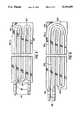
- FIG. 1is a diagrammatic representation of one embodiment of the sensor of the present invention
- FIG. 1Ais a partial diagrammatic representation of an alternative embodiment of the present invention.
- FIG. 2is a diagrammatic representation of another embodiment of the sensor of the present invention.
- FIG. 3is a diagrammatic representation of the embodiment of FIG. 2 in use
- FIG. 4is a diagrammatic representation of yet another embodiment of the sensor of the present invention.
- FIG. 5is a diagrammatic representation of another embodiment of the sensor of the present invention.
- FIG. 6is a diagrammatic representation of another embodiment of the sensor of the present invention.
- FIG. 1depicts a sensor 2 which includes a resilient means 4 through which fluid under pressure can flow from an inlet 6 for the resilient means 4 through an open outlet 8 for the resilient means 4.
- the resilient means 4can be in the form of a tube, cell or other form of fluid passage 10 adapted to allow fluid such as air to flow from the inlet 6 through the outlet 8 when the passage 10 is not collapsed by the weight of a patient as described herein.
- the passage 10is in the form of a tube attached to or made integral with a thin and flexible plastic base 12 by means of heat sealing, gluing and the like.
- the passage 10is formed by heat sealing or welding together two or more layers of plastic film. Heat sealing or welding together layers of plastic film is described in U.S. Pat. No. 4,483,030 to Flick et al. which is assigned to Medisearch PR, Inc., a wholly owned subsidiary of the same assignee as this invention, Gaymar Industries, Inc.
- the resilient means 4includes at least one fluid passage 10 which is oriented in a serpentine manner in the plane of base 12 as depicted in FIG. 1.
- the passage 10includes a serpentine pattern which includes five turns. More or less turns can be provided if desired.
- undesirable shear forces and hammocking between the patient and the resilient means 4can be reduced by providing slits 14 which extend through the base 12 and are located between the various serpentine loops of the fluid passage 10.
- a fluid supplying means 16is connected to the inlet 6 for continuously supplying fluid under pressure toward the resilient means 4 in the direction of arrow 18.
- the fluid supplying means 16includes a pump having a pump outlet 20 connected for pumping fluid such as air to inlet 6.
- the open outlet 8is vented directly to the atmosphere.
- the pumpcan also include a pump inlet 22, and the open outlet 8 of the resilient means 4 can be connected to such pump inlet at 24 rather than being vented directly to the atmosphere.
- the pump inlet 22includes a first end 26 connected to the pump and an opposite second end 28 vented to the atmosphere, the open outlet 8 being connected to the pump inlet 22 between ends 26 and 28.
- the pump inlet 22can be vented to the atmosphere through a restriction or orifice 30 which is positioned between end 28 and open outlet 8.
- An example of such an orificeis a flat plate or disc having an aperture therethrough the dimensions of which will depend upon the degree to which it is desired to restrict the loss of air from the system at the position of the orifice.
- Such an orificeis known in the art. In this manner, inlet air can be provided to the pump from the atmosphere at end 28 through orifice 30 and from the open outlet 8.
- the orifice 30permits maintaining a supply of make-up air as well as compensating for atmospheric pressure changes.
- the orifice 30allows the return air from the resilient means that is connected to the pump inlet to fall below atmospheric pressure if the resilient means is occluded or restricted. This results in a larger pressure drop across the resilient means than would exist if it were simply exhausted to atmosphere.
- the orifice restriction to atmospherealso allows air from atmosphere to enter the system if the otherwise closed system requires it such as when barometric pressure changes, temperature changes, air leaks from the pump or the sensor flow demand changes.
- orifice 30Use of the orifice 30 is optional. In the preferred embodiment, the exhaust air will vent directly to atmosphere as described above. If desired, an orifice 31 can be provided similar to orifice 30 but located in the conduit which forms the open outlet 8 as depicted in FIG. 1. In particular, orifice 31 will create back pressure in the sensor the degree of which will depend upon the weight of the patient.
- Switching means 32is connected between the resilient means 4 and the fluid supplying means 16 for controlling indicating means 34 in response to changes in pressure in the fluid supplied by the fluid supplying means, as described herein. Indicating means 34 indicates when there has been a change in such pressure.
- the switching means 32is connected to the inlet 6 through a conduit 36 such that the fluid supplying means or pump 16 can pump air under pressure to the resilient means 4 and to the switching means 32.
- Switching means 32includes normally closed contacts.
- the switching meansincludes a plurality of contact means 38, 40 each of which is electrically connected to a respective indicating means.
- contact means 38includes normally closed contacts 42, 44 which are electrically connected to indicating means 34.
- Indicating means 34can be in the form of, for example, an audio and/or visual alarm.
- contact means 40includes normally closed contacts 46, 48 which are electrically connected to an indicating means by connecting the signal line to the nurse's call at a nurse's station to its signal common 49. Although the nurse's call is not shown, arrow 50 is representative of line 52 extending to such an indicating means.
- the switching means 32can be in the form of, for example, a pressure switch or other pressure sensing device such as a transducer. In the embodiment of FIG. 1, the switching means is in the form of a pressure switch with normally closed contacts.
- the pump 16provides low pressure air to the resilient means through inlet 6 and air passage 10 and to the switching means 32 through conduit 36.
- the weight of a patient lying on the resilient means 4will cause the passage 10 of the resilient means 4 to collapse thereby preventing air flow to continue through passage 10.
- Thiscauses the pressure at the outlet 20 of the pump to increase.
- Such increase in pressureis sensed by the pressure switch of switching means 32 causing the normally closed contacts 42, 44 and 46, 48 to open thereby deactivating the indicating means. If the patient were to get up or otherwise leave the bed, the collapsed passage 10 of the resilient means 4 would rebound to its original open configuration allowing air to continue to flow therethrough and to exit at the open outlet 8.
- the resilient means 4is of the type which can be positioned directly beneath or on top of a bed mattress, or if desired between the mattress and a tissue pressure relieving bed pad or cushion such as a foam pad, or an air cushion as is described in U.S. Pat. No. 4,483,030, referred to above, or U.S. Pat. No. 4,454,615 to Whitney which is assigned to Medisearch PR, Inc. to provide signalling means to a caregiver when a patient is out of the bed.
- a similar resilient meanscan be positioned between the bed mattress and an overlay pressure relieving cushion to serve as a bottoming sensor to provide signalling means to the caregiver if the overlay becomes compressed between the patient and the mattress to the extent to cause the patient to feel the presence of the mattress.
- the overlayis an air cushion of the type described in U.S. Pat. Nos. 4,483,030 or 4,454,615 which might lose air by leakage or in some other manner, or a foam cushion which does not provide satisfactory patient support, then the patient will "bottom” causing the patient to feel the presence of the mattress and to lose the benefit of the overlay.
- a resilient means 4'can be provided to signal the caregiver in the event that such bottoming occurs.
- the sensor 2 with resilient means 4'functions in the same manner as with resilient means 4, and like reference numerals have been used with a prime designation to designate similar parts.
- Sensor 4'does not include slits 14 although such slits can be provided if desired.
- the switching means 32'includes normally open contacts.
- the switching meansincludes a plurality of contact means 38', 40' each of which is electrically connected to a respective indicating means (not shown).
- contact means 38'includes normally open contacts 42' 44' which can be electrically connected to an indicating means in the form of, for example, an audio and/or visual alarm (not shown) in the same manner in which contacts 42, 44 are connected to alarm 34.
- contact means 40'include normally open contacts 46', 48' which can be electrically connected to a nurse's call at a nurse's station.
- the switching means 32'can be in the form of, for example, a pressure switch or other pressure sensing device such as a transducer. In the embodiment of FIG. 1, the switching means 32' is in the form of a pressure switch with normally open contacts.
- the pump 16provides low pressure air to the resilient means 4' through inlet 6' and air passage 10' and to the switching means 32' through conduit 36'.
- a patient lying upon an overlay such as an air pad positioned on top of the resilient means 4'will not engage the resilient means 4' if there is sufficient air in the pad. Since the patient will not be engaging the resilient means 4', the air will be free to flow through the passage 10' as long as sufficient pressure is provided by pump 16 and to exit at the open outlet 8'. In such a mode, the air pressure at the outlet 20' of the pump will be low and will not overcome the normally open position of the contacts 42', 44' and 46', 48' and therefore the indicating means will not be activated.
- the sensor 2can include at least one switching means which includes normally open contacts and at least another switching means which includes normally closed contacts.
- the sensor 2includes the resilient means 4 for use in sensing when a patient leaves a bed and the resilient means 4' for use in sensing bottoming of the patient.
- resilient means 4functions in combination with normally closed contacts 42, 44 and 46, 48
- resilient means 4'functions in combination with normally open contacts 42', 44' and 46', 48'.
- the fluid supplying meansis in the form of pump 16 having two fluid supply outlets 20 and 20' which function independently of each other, fluid supply outlet 20 supplying fluid to control activation of the normally closed contacts and fluid supply outlet 20' supplying fluid to control activation of the normally open contacts.
- Outlets 20 and 20'can be caused to function independently by having each associated with a separate pump 16', 16" as depicted in FIG. 1.
- a single pumpcan be used with an orifice or pressure relief valve or the like being provided in the line 20 and another orifice or pressure relief valve or the like being provided in line 20'.
- a sensor 102which includes a resilient means 104 through which fluid under pressure can flow from an inlet 106 for the resilient means 104 through an open outlet 108 for the resilient means 104.
- the resilient means 104can be fabricated as described above regarding resilient means 4.
- resilient means 104includes a plurality of tubes, cells or other fluid passages 110, 110', 110" adapted to allow fluid such as air to flow from inlet 106 through the outlet 108 with respect to those fluid passages 110, 110', 110" which are not collapsed by the weight of a patient as described herein.
- fluid passages 110' and 110"be non-collapsible where they extend upon the resilient means 104 adjacent to fluid passage 110, and that fluid passage 110" also be non-collapsible where it extends upon the resilient means 104 adjacent fluid passage 110'.
- the outlet 108be non-collapsible at least where it extends upon the resilient means 104 from its connection to fluid passage 110 to its connection to fluid passage 110".
- a fluid supplying means 116such as a pump is connected at pump outlet 120 to the inlet 106 for continuously supplying fluid under pressure toward the resilient means 104 in the direction of arrows 118, 118', 118".
- inlet 106is connected to a manifold 122.
- Each fluid passage 110, 110', 110"includes a respective fluid passage inlet 124, 124', 124" which is connected to manifold 122.
- Inlets 124, 124', 124"can be connected directly to manifold 122 or, as depicted in FIG. 2, can be connected to the manifold through a pneumatic connector 126.
- An example of such a pneumatic connectoris described in U.S. Pat. No.
- a plurality of switching means 132, 132', 132" similar to switching means 32 of FIG. 1is provided, each switching means being connected between the fluid supplying means 116 and a respective fluid passage 110, 110', 110" as depicted in FIG. 2.
- a plurality of indicating means diagrammatically represented at 134, 134', 134"is provided, each indicating means being connected to a respective switching means.
- each switching means 132, 132', 132"can include normally open contacts (not shown), the contacts in each switching means being electrically connected to a respective indicating means 134, 134' , 134".
- Orifices 130, 130', 130" similar to orifice 30 of FIG. 1Aare connected between the fluid supplying means 116 and a respective switching means 132, 132', 132".
- the senor of FIG. 2includes a plurality of fluid passages 10, 110', 110" which operate independently as far as the patient load is concerned.
- FIG. 2depicts three fluid passages 110, 110', 110". However, more or less fluid passages can be used as desired. This feature allows the detection of movement of a patient as, for example, when the patient is getting close to an edge of the bed.
- FIG. 3depicts a bed B, resilient means 104 and patient P.
- air supplied at low pressure by fluid supplying means 116will be free to flow through inlet 106, manifold 122, inlets 124, 124', 124" and passages 110, 110', 110" and to exit at the common open outlet 108 to be vented directly to atmosphere at 108'.
- Such atmospheric exhaust airis preferably directed away from the patient by locating the end 108' off of the bed or near the pump. In such a mode, the air pressure sensed at each switching means will be low and will not overcome the normally open position of the contacts in each respective switching means 132, 132', 132".
- the indicating means 134, 134', 134"will be activated.
- the patientWhen a patient P is positioned in the bed B, the patient will typically be placed in the middle of the bed as depicted in FIG. 3 such that the weight of the patient will bear against the passage 110' causing passage 110' to collapse thereby preventing air flow to continue through passage 110'.
- Thiscauses an increase in pressure to be sensed by the switching means 132' thereby causing the normally open contacts in switching means 132' to close.
- Such an increase in pressureis facilitated by the presence of the orifice 130'. Closure of such contacts will activate the indicating means 134' which can include a lamp positioned in the middle of a control panel C designating that the patient is in the middle of the bed B.
- Airwill continue to flow through passages 110, 110" thereby maintaining at a relatively low level the air pressure sensed by switching means 132, 132", the normally open contacts in switching means 132, 132" continuing to be at their normally open position.
- the patientwill collapse passage 110 causing an increase in pressure to be sensed by the switching means 132 thereby causing the normally open contacts in switching means 132 to close.
- Such an increase in pressurewill be facilitated by the presence of the orifice 130. Closure of such contacts will activate the indicating means 134 which can include a lamp positioned in the left-hand side of control panel C designating that the patient has moved toward edge B1.
- the fluid supplying means of the present inventioncan be the same pump used to inflate an air cushion-type overlay such as is manufactured by Gaymar Industries under Model Numbers APP30, APP50, AFP255 and AFP355.
- FIG. 4depicts a modification of the switching means 32 of FIG. 1.
- the switching means 32is replaced by a switching means 200 which includes a pressure switch 202, coupled to the fluid supplying means 16 by conduit 36, and a time delay relay 204.
- Pressure switch 202includes contact means 206 which includes normally open contacts 208, 210.
- An example of a time delay 204 which can be used in the present inventionis, without limitation, type CWD-38-66000 sold by Potter Brumfield.
- the circuitry of time delay relay 204is not depicted except for the normally closed contact means 212 and 214 and the relay coil 216.
- contact means 212will connect the 120 VAC to the alarm at 34 and the other contact means 214 will connect the nurse's call signal line to its circuit common 217 to alert the attending clinicians.
- air pressurewill increase in the pressure switch 202 causing the contacts 208, 210 of the contact means 206 to close and the time delay relay coil 216 to be energized.
- the normally closed relay contact means 212 and 214will open thereby deactivating the indicating means 34 and the nurse's call. It should be noted that the time delay can be set at zero or the delay circuit can be bypassed or eliminated if no delay is desired
- inadvertent activation of the indicating meanscan also be minimized by providing non-collapsible conduits except in the region of the fluid passages such as at 10, 10' and 110, 110', 110" which are intended to be collapsed by the weight of the patient as described herein.
- the passages 110', 110" and the outlet 108are provided with lengths which are non-collapsible.
- FIGS. 5 and 6depict two different flow patterns of a sensor 300 of the present invention. Both versions are made of two layers of plastic film 302 heat sealed to create the sensor flow passages 304.
- the film materialcan be polyvinyl chloride, polyurethane, polyethylene, nylon or other suitable thin flexible material.
- Heat seals 306are created adjacent to the flow passages 304.
- Slits 308are optional but when used allow unrestricted movement of the sensor 300 in the plane of the sensor so that shear forces on the patient are reduced.
- Plastic hose or tubing 310made of material that is similar to that of the film 302 is heat sealed into the sensor air passage 304 in order to make pneumatic connection to the sensor 300.
- Pneumatic connectors 312are inserted or connected to the tubing 310 and the tubes 314 that connect to the pump. An example of such pneumatic connectors is described in U.S. Pat. No. 4,068,870.
Landscapes
- Business, Economics & Management (AREA)
- Emergency Management (AREA)
- Physics & Mathematics (AREA)
- General Physics & Mathematics (AREA)
- Invalid Beds And Related Equipment (AREA)
Abstract
Description
______________________________________ 4,228,426 Roberts 4,242,672 Gault 4,638,307 Swartout 4,700,180 Vance ______________________________________
Claims (33)
Priority Applications (1)
| Application Number | Priority Date | Filing Date | Title |
|---|---|---|---|
| US07/668,062US5140309A (en) | 1991-03-12 | 1991-03-12 | Bed signalling apparatus |
Applications Claiming Priority (1)
| Application Number | Priority Date | Filing Date | Title |
|---|---|---|---|
| US07/668,062US5140309A (en) | 1991-03-12 | 1991-03-12 | Bed signalling apparatus |
Publications (1)
| Publication Number | Publication Date |
|---|---|
| US5140309Atrue US5140309A (en) | 1992-08-18 |
Family
ID=24680852
Family Applications (1)
| Application Number | Title | Priority Date | Filing Date |
|---|---|---|---|
| US07/668,062Expired - LifetimeUS5140309A (en) | 1991-03-12 | 1991-03-12 | Bed signalling apparatus |
Country Status (1)
| Country | Link |
|---|---|
| US (1) | US5140309A (en) |
Cited By (48)
| Publication number | Priority date | Publication date | Assignee | Title |
|---|---|---|---|---|
| US5808552A (en)* | 1996-11-25 | 1998-09-15 | Hill-Rom, Inc. | Patient detection system for a patient-support device |
| WO1999044179A1 (en) | 1998-02-27 | 1999-09-02 | Hill-Rom, Inc. | Bed exit detection apparatus |
| US6133837A (en)* | 1999-03-05 | 2000-10-17 | Hill-Rom, Inc. | Patient position system and method for a support surface |
| WO2001033457A1 (en)* | 1999-10-29 | 2001-05-10 | Strategic Visualization, Inc. | Apparatus and method for providing medical services over a communication network |
| US6255956B1 (en)* | 1999-08-27 | 2001-07-03 | Gloria J. Tingley | Seat operated switch and warning system |
| US20020187332A1 (en)* | 1998-07-22 | 2002-12-12 | Flick Roland E. | Gelatinous composite article and construction |
| US20030010345A1 (en)* | 2002-08-02 | 2003-01-16 | Arthur Koblasz | Patient monitoring devices and methods |
| US20030028157A1 (en)* | 2001-07-13 | 2003-02-06 | Jusiak Joel T. | Support device with integrated pressure adjustment device and method of use |
| WO2003017221A1 (en)* | 2001-08-14 | 2003-02-27 | Becatech Ltd | Alarm |
| EP1271441A3 (en)* | 2001-06-25 | 2003-06-04 | Colin Corporation | Patient detecting apparatus |
| US20030216670A1 (en)* | 2002-05-17 | 2003-11-20 | Beggs George R. | Integral, flexible, electronic patient sensing and monitoring system |
| US6689079B2 (en) | 2001-07-13 | 2004-02-10 | Gaymar Industries, Inc. | Support device with pressure adjustment section and method of use |
| US6739001B2 (en) | 2001-04-27 | 2004-05-25 | Gaymar Industries, Inc. | Cushioning device including a restraint structure |
| US6791460B2 (en) | 1999-03-05 | 2004-09-14 | Hill-Rom Services, Inc. | Patient position detection apparatus for a bed |
| US6813790B2 (en) | 2002-02-28 | 2004-11-09 | Gaymar Industries, Inc. | Self-adjusting cushioning device |
| US6847301B1 (en) | 2003-03-06 | 2005-01-25 | Personal Safety Corporation | Patient position monitoring device |
| US20050273940A1 (en)* | 2004-04-30 | 2005-12-15 | Robert Petrosenko | Lack of patient movement monitor and method |
| US7253366B2 (en) | 2004-08-09 | 2007-08-07 | Hill-Rom Services, Inc. | Exit alarm for a hospital bed triggered by individual load cell weight readings exceeding a predetermined threshold |
| US20070285269A1 (en)* | 2006-06-07 | 2007-12-13 | Winncare International, Societe Par Actions Simplifiee | Device against bottoming-out of a flexible support |
| US20080117061A1 (en)* | 2006-11-16 | 2008-05-22 | Gaymar Industries, Inc. | Electroluminescent lighting for a managed-care setting |
| US20080271245A1 (en)* | 2007-05-04 | 2008-11-06 | Gaymar Industries, Inc. | Inflatable mattress with uniform restraint |
| ITBZ20080033A1 (en)* | 2008-09-10 | 2010-03-11 | Diego Albertini | EQUIPMENT FOR REPORTING THE PRESENCE OF PEOPLE, ANIMALS AND THINGS. |
| US7698765B2 (en) | 2004-04-30 | 2010-04-20 | Hill-Rom Services, Inc. | Patient support |
| US20100308846A1 (en)* | 2009-06-05 | 2010-12-09 | Gilles Camus | Pressure sensor comprising a capacitive cell and support device comprising said sensor |
| US7849545B2 (en) | 2006-11-14 | 2010-12-14 | Hill-Rom Industries Sa | Control system for hospital bed mattress |
| ITMI20091447A1 (en)* | 2009-08-07 | 2011-02-08 | Margaritis Giovanni Battista De | DEVICE TO FIND THE PRESENCE OF NON-SELF-SUFFICIENT PEOPLE OR CHILDREN IN BEDS, WHEELCHAIRS, ARMCHAIRS AND THE LIKE. |
| US7937791B2 (en) | 2004-04-30 | 2011-05-10 | Hill-Rom Services, Inc. | Pressure relief surface |
| US8046625B2 (en) | 2008-02-22 | 2011-10-25 | Hill-Rom Services, Inc. | Distributed fault tolerant architecture for a healthcare communication system |
| US8090478B2 (en) | 2005-06-10 | 2012-01-03 | Hill-Rom Services, Inc. | Control for pressurized bladder in a patient support apparatus |
| US8108957B2 (en) | 2007-05-31 | 2012-02-07 | Hill-Rom Services, Inc. | Pulmonary mattress |
| US20120182148A1 (en)* | 2011-01-18 | 2012-07-19 | Alan Paine | Bed pre-exit patient monitor |
| US8419660B1 (en) | 2005-06-03 | 2013-04-16 | Primus Medical, Inc. | Patient monitoring system |
| US8717181B2 (en) | 2010-07-29 | 2014-05-06 | Hill-Rom Services, Inc. | Bed exit alert silence with automatic re-enable |
| EP1912537A4 (en)* | 2005-07-26 | 2014-05-07 | Hill Rom Services Inc | System and method of controlling an air mattress |
| US8844079B2 (en) | 2005-07-08 | 2014-09-30 | Hill-Rom Services, Inc. | Pressure control for a hospital bed |
| US20140331408A1 (en)* | 2013-05-08 | 2014-11-13 | Siemens Aktiengesellscaft | Patient support apparatus |
| US20150025327A1 (en)* | 2013-07-18 | 2015-01-22 | Bam Labs, Inc. | Device and Method of Monitoring a Position and Predicting an Exit of a Subject on or from a Substrate |
| US8973186B2 (en) | 2011-12-08 | 2015-03-10 | Hill-Rom Services, Inc. | Optimization of the operation of a patient-support apparatus based on patient response |
| EP2995242A1 (en) | 2014-09-11 | 2016-03-16 | Hill-Rom S.A.S. | Patient support apparatus |
| CN106793980A (en)* | 2014-10-13 | 2017-05-31 | 皇家飞利浦有限公司 | Patient monitoring system and method |
| US9707141B2 (en) | 2005-07-08 | 2017-07-18 | Hill-Rom Services, Inc. | Patient support |
| US10136815B2 (en) | 2012-09-24 | 2018-11-27 | Physio-Control, Inc. | Patient monitoring device with remote alert |
| US10292605B2 (en) | 2012-11-15 | 2019-05-21 | Hill-Rom Services, Inc. | Bed load cell based physiological sensing systems and methods |
| US11357683B2 (en) | 2005-07-08 | 2022-06-14 | Hill-Rom Services, Inc. | Foot zone of a mattress |
| CN115154103A (en)* | 2022-09-01 | 2022-10-11 | 中国人民解放军总医院第五医学中心 | Direct turn-over bedspread |
| US11504061B2 (en) | 2017-03-21 | 2022-11-22 | Stryker Corporation | Systems and methods for ambient energy powered physiological parameter monitoring |
| US12023287B2 (en) | 2012-09-05 | 2024-07-02 | Stryker Corporation | Inflatable mattress and control methods |
| US12251243B2 (en) | 2008-02-22 | 2025-03-18 | Hill-Rom Services, Inc. | Distributed healthcare communication system |
Citations (20)
| Publication number | Priority date | Publication date | Assignee | Title |
|---|---|---|---|---|
| US3439358A (en)* | 1965-11-30 | 1969-04-15 | George Washington Ltd | Activity detectors |
| US3533095A (en)* | 1969-01-02 | 1970-10-06 | James Collins | Inflatable pad with alarm |
| US3781843A (en)* | 1971-04-15 | 1973-12-25 | Sanders Associates Inc | Bed guard system |
| US3822425A (en)* | 1971-07-09 | 1974-07-09 | J Scales | Inflatable support appliance |
| US4020482A (en)* | 1976-04-19 | 1977-04-26 | Feldl Erich J | Patient monitor |
| US4068870A (en)* | 1976-04-02 | 1978-01-17 | Gaymar Industries Incorporated | Flexible hose coupling |
| US4175263A (en)* | 1977-04-25 | 1979-11-20 | Triad & Associates, Inc. | Technique for monitoring whether an individual is moving from a particular area |
| US4216469A (en)* | 1976-06-23 | 1980-08-05 | Multisafe Ag | Alarm system for detecting changes in load on terrain |
| US4228426A (en)* | 1978-09-29 | 1980-10-14 | Roberts William A | Hospital bed monitor |
| US4242672A (en)* | 1977-11-09 | 1980-12-30 | Gault Robert L | Patient monitoring system and switch |
| US4337726A (en)* | 1980-07-07 | 1982-07-06 | Czekajewski Jan A | Animal activity monitor and behavior processor |
| US4391009A (en)* | 1980-10-17 | 1983-07-05 | Huntleigh Medical Ltd. | Ventilated body support |
| US4454615A (en)* | 1982-05-03 | 1984-06-19 | Medisearch Pr, Inc. | Air pad with integral securement straps |
| US4483030A (en)* | 1982-05-03 | 1984-11-20 | Medisearch Pr, Inc. | Air pad |
| US4633237A (en)* | 1984-07-11 | 1986-12-30 | Kenneth A. Tucknott | Patient bed alarm system |
| US4638307A (en)* | 1985-10-15 | 1987-01-20 | Swartout Willson C | Patient position monitoring system |
| US4700180A (en)* | 1983-05-04 | 1987-10-13 | Vance Dwight A | Apparatus to indicate when a patient has evacuated a bed |
| US4899133A (en)* | 1988-02-08 | 1990-02-06 | Detex Corporation | Programmable movement analyzer with a plurality of mercury switches |
| US4907845A (en)* | 1988-09-16 | 1990-03-13 | Salomon Sa | Bed patient monitoring system |
| US4935968A (en)* | 1985-05-10 | 1990-06-26 | Mediscus Products, Ltd. | Patient support appliances |
- 1991
- 1991-03-12USUS07/668,062patent/US5140309A/ennot_activeExpired - Lifetime
Patent Citations (20)
| Publication number | Priority date | Publication date | Assignee | Title |
|---|---|---|---|---|
| US3439358A (en)* | 1965-11-30 | 1969-04-15 | George Washington Ltd | Activity detectors |
| US3533095A (en)* | 1969-01-02 | 1970-10-06 | James Collins | Inflatable pad with alarm |
| US3781843A (en)* | 1971-04-15 | 1973-12-25 | Sanders Associates Inc | Bed guard system |
| US3822425A (en)* | 1971-07-09 | 1974-07-09 | J Scales | Inflatable support appliance |
| US4068870A (en)* | 1976-04-02 | 1978-01-17 | Gaymar Industries Incorporated | Flexible hose coupling |
| US4020482A (en)* | 1976-04-19 | 1977-04-26 | Feldl Erich J | Patient monitor |
| US4216469A (en)* | 1976-06-23 | 1980-08-05 | Multisafe Ag | Alarm system for detecting changes in load on terrain |
| US4175263A (en)* | 1977-04-25 | 1979-11-20 | Triad & Associates, Inc. | Technique for monitoring whether an individual is moving from a particular area |
| US4242672A (en)* | 1977-11-09 | 1980-12-30 | Gault Robert L | Patient monitoring system and switch |
| US4228426A (en)* | 1978-09-29 | 1980-10-14 | Roberts William A | Hospital bed monitor |
| US4337726A (en)* | 1980-07-07 | 1982-07-06 | Czekajewski Jan A | Animal activity monitor and behavior processor |
| US4391009A (en)* | 1980-10-17 | 1983-07-05 | Huntleigh Medical Ltd. | Ventilated body support |
| US4454615A (en)* | 1982-05-03 | 1984-06-19 | Medisearch Pr, Inc. | Air pad with integral securement straps |
| US4483030A (en)* | 1982-05-03 | 1984-11-20 | Medisearch Pr, Inc. | Air pad |
| US4700180A (en)* | 1983-05-04 | 1987-10-13 | Vance Dwight A | Apparatus to indicate when a patient has evacuated a bed |
| US4633237A (en)* | 1984-07-11 | 1986-12-30 | Kenneth A. Tucknott | Patient bed alarm system |
| US4935968A (en)* | 1985-05-10 | 1990-06-26 | Mediscus Products, Ltd. | Patient support appliances |
| US4638307A (en)* | 1985-10-15 | 1987-01-20 | Swartout Willson C | Patient position monitoring system |
| US4899133A (en)* | 1988-02-08 | 1990-02-06 | Detex Corporation | Programmable movement analyzer with a plurality of mercury switches |
| US4907845A (en)* | 1988-09-16 | 1990-03-13 | Salomon Sa | Bed patient monitoring system |
Cited By (101)
| Publication number | Priority date | Publication date | Assignee | Title |
|---|---|---|---|---|
| US5808552A (en)* | 1996-11-25 | 1998-09-15 | Hill-Rom, Inc. | Patient detection system for a patient-support device |
| US6067019A (en)* | 1996-11-25 | 2000-05-23 | Hill-Rom, Inc. | Bed exit detection apparatus |
| WO1999044179A1 (en) | 1998-02-27 | 1999-09-02 | Hill-Rom, Inc. | Bed exit detection apparatus |
| US20020187332A1 (en)* | 1998-07-22 | 2002-12-12 | Flick Roland E. | Gelatinous composite article and construction |
| US6843873B2 (en) | 1998-07-22 | 2005-01-18 | Gaymar Industries, Inc. | Method of making a gelatinous composite |
| US6767621B2 (en) | 1998-07-22 | 2004-07-27 | Gaymar Industries, Inc. | Gelatinous composite article and construction |
| US20080010747A1 (en)* | 1999-03-05 | 2008-01-17 | Dixon Stephen A | Electrical Connector Assembly Suitable for a Bed Footboard |
| US7986242B2 (en) | 1999-03-05 | 2011-07-26 | Hill-Rom Services, Inc. | Electrical connector assembly suitable for a bed footboard |
| US20050035871A1 (en)* | 1999-03-05 | 2005-02-17 | Hill-Rom Services, Inc. | Patient position detection apparatus for a bed |
| US6133837A (en)* | 1999-03-05 | 2000-10-17 | Hill-Rom, Inc. | Patient position system and method for a support surface |
| US6791460B2 (en) | 1999-03-05 | 2004-09-14 | Hill-Rom Services, Inc. | Patient position detection apparatus for a bed |
| US20050166324A1 (en)* | 1999-03-05 | 2005-08-04 | Dixon Stephen A. | Romovable footboard for a hospital bed |
| US6255956B1 (en)* | 1999-08-27 | 2001-07-03 | Gloria J. Tingley | Seat operated switch and warning system |
| WO2001033457A1 (en)* | 1999-10-29 | 2001-05-10 | Strategic Visualization, Inc. | Apparatus and method for providing medical services over a communication network |
| US20030190023A1 (en)* | 1999-10-29 | 2003-10-09 | Strategic Visualization, Inc. | Apparatus and method for providing medical services over a communication network |
| US6739001B2 (en) | 2001-04-27 | 2004-05-25 | Gaymar Industries, Inc. | Cushioning device including a restraint structure |
| EP1271441A3 (en)* | 2001-06-25 | 2003-06-04 | Colin Corporation | Patient detecting apparatus |
| US6689079B2 (en) | 2001-07-13 | 2004-02-10 | Gaymar Industries, Inc. | Support device with pressure adjustment section and method of use |
| US20030028157A1 (en)* | 2001-07-13 | 2003-02-06 | Jusiak Joel T. | Support device with integrated pressure adjustment device and method of use |
| GB2393834A (en)* | 2001-08-14 | 2004-04-07 | Becatech Ltd | Alarm |
| GB2393834B (en)* | 2001-08-14 | 2004-12-29 | Becatech Ltd | Alarm |
| US20040201487A1 (en)* | 2001-08-14 | 2004-10-14 | Benson Alan Howard | Alarm |
| WO2003017221A1 (en)* | 2001-08-14 | 2003-02-27 | Becatech Ltd | Alarm |
| US6813790B2 (en) | 2002-02-28 | 2004-11-09 | Gaymar Industries, Inc. | Self-adjusting cushioning device |
| US6917293B2 (en) | 2002-05-17 | 2005-07-12 | Tactilitics, Inc. | Integral, flexible, electronic patient sensing and monitoring system |
| US20030216670A1 (en)* | 2002-05-17 | 2003-11-20 | Beggs George R. | Integral, flexible, electronic patient sensing and monitoring system |
| US20030010345A1 (en)* | 2002-08-02 | 2003-01-16 | Arthur Koblasz | Patient monitoring devices and methods |
| US6847301B1 (en) | 2003-03-06 | 2005-01-25 | Personal Safety Corporation | Patient position monitoring device |
| US20050273940A1 (en)* | 2004-04-30 | 2005-12-15 | Robert Petrosenko | Lack of patient movement monitor and method |
| US7973666B2 (en) | 2004-04-30 | 2011-07-05 | Hill-Rom Services, Inc. | Graphical patient movement monitor |
| US7557718B2 (en) | 2004-04-30 | 2009-07-07 | Hill-Rom Services, Inc. | Lack of patient movement monitor and method |
| US20090270770A1 (en)* | 2004-04-30 | 2009-10-29 | Robert Petrosenko | Graphical patient movement monitor |
| US8196240B2 (en) | 2004-04-30 | 2012-06-12 | Hill-Rom Services, Inc. | Pressure relief surface |
| US7698765B2 (en) | 2004-04-30 | 2010-04-20 | Hill-Rom Services, Inc. | Patient support |
| US8146191B2 (en) | 2004-04-30 | 2012-04-03 | Hill-Rom Services, Inc. | Patient support |
| US7937791B2 (en) | 2004-04-30 | 2011-05-10 | Hill-Rom Services, Inc. | Pressure relief surface |
| US7253366B2 (en) | 2004-08-09 | 2007-08-07 | Hill-Rom Services, Inc. | Exit alarm for a hospital bed triggered by individual load cell weight readings exceeding a predetermined threshold |
| US7437787B2 (en) | 2004-08-09 | 2008-10-21 | Hill-Rom Services, Inc. | Load-cell based hospital bed control |
| US8419660B1 (en) | 2005-06-03 | 2013-04-16 | Primus Medical, Inc. | Patient monitoring system |
| US8620477B2 (en) | 2005-06-10 | 2013-12-31 | Hill-Rom Services, Inc. | Control for pressurized bladder in a patient support apparatus |
| US9107511B2 (en) | 2005-06-10 | 2015-08-18 | Hill-Rom Services, Inc. | Control for pressurized bladder in a patient support apparatus |
| US8090478B2 (en) | 2005-06-10 | 2012-01-03 | Hill-Rom Services, Inc. | Control for pressurized bladder in a patient support apparatus |
| US11357683B2 (en) | 2005-07-08 | 2022-06-14 | Hill-Rom Services, Inc. | Foot zone of a mattress |
| US8844079B2 (en) | 2005-07-08 | 2014-09-30 | Hill-Rom Services, Inc. | Pressure control for a hospital bed |
| US9707141B2 (en) | 2005-07-08 | 2017-07-18 | Hill-Rom Services, Inc. | Patient support |
| US10507147B2 (en) | 2005-07-08 | 2019-12-17 | Hill-Rom Services, Inc. | Patient support |
| US8745788B2 (en) | 2005-07-26 | 2014-06-10 | Hill-Rom Services. Inc. | System and method for controlling an air mattress |
| EP1912537A4 (en)* | 2005-07-26 | 2014-05-07 | Hill Rom Services Inc | System and method of controlling an air mattress |
| US20070285269A1 (en)* | 2006-06-07 | 2007-12-13 | Winncare International, Societe Par Actions Simplifiee | Device against bottoming-out of a flexible support |
| US7849545B2 (en) | 2006-11-14 | 2010-12-14 | Hill-Rom Industries Sa | Control system for hospital bed mattress |
| US20080117061A1 (en)* | 2006-11-16 | 2008-05-22 | Gaymar Industries, Inc. | Electroluminescent lighting for a managed-care setting |
| US7954186B2 (en) | 2007-05-04 | 2011-06-07 | Gaymar Industries, Inc. | Inflatable mattress with uniform restraint |
| US20080271245A1 (en)* | 2007-05-04 | 2008-11-06 | Gaymar Industries, Inc. | Inflatable mattress with uniform restraint |
| US8108957B2 (en) | 2007-05-31 | 2012-02-07 | Hill-Rom Services, Inc. | Pulmonary mattress |
| US8584279B2 (en) | 2007-05-31 | 2013-11-19 | Hill-Rom Services, Inc. | Pulmonary mattress |
| US8169304B2 (en) | 2008-02-22 | 2012-05-01 | Hill-Rom Services, Inc. | User station for healthcare communication system |
| US12251243B2 (en) | 2008-02-22 | 2025-03-18 | Hill-Rom Services, Inc. | Distributed healthcare communication system |
| US10638983B2 (en) | 2008-02-22 | 2020-05-05 | Hill-Rom Services, Inc. | Distributed healthcare communication system |
| US8598995B2 (en) | 2008-02-22 | 2013-12-03 | Hill-Rom Services, Inc. | Distributed healthcare communication system |
| US8392747B2 (en) | 2008-02-22 | 2013-03-05 | Hill-Rom Services, Inc. | Distributed fault tolerant architecture for a healthcare communication system |
| US10307113B2 (en) | 2008-02-22 | 2019-06-04 | Hill-Rom Services, Inc. | Distributed healthcare communication system |
| US8384526B2 (en) | 2008-02-22 | 2013-02-26 | Hill-Rom Services, Inc. | Indicator apparatus for healthcare communication system |
| US9955926B2 (en) | 2008-02-22 | 2018-05-01 | Hill-Rom Services, Inc. | Distributed healthcare communication system |
| US8762766B2 (en) | 2008-02-22 | 2014-06-24 | Hill-Rom Services, Inc. | Distributed fault tolerant architecture for a healthcare communication system |
| US8803669B2 (en) | 2008-02-22 | 2014-08-12 | Hill-Rom Services, Inc. | User station for healthcare communication system |
| US8046625B2 (en) | 2008-02-22 | 2011-10-25 | Hill-Rom Services, Inc. | Distributed fault tolerant architecture for a healthcare communication system |
| US11696731B2 (en) | 2008-02-22 | 2023-07-11 | Hill-Room Services, Inc. | Distributed healthcare communication method |
| US8456286B2 (en) | 2008-02-22 | 2013-06-04 | Hill-Rom Services, Inc. | User station for healthcare communication system |
| US11944467B2 (en) | 2008-02-22 | 2024-04-02 | Hill-Rom Services, Inc. | Distributed healthcare communication system |
| US9517035B2 (en) | 2008-02-22 | 2016-12-13 | Hill-Rom Services, Inc. | Distributed healthcare communication system |
| US9299242B2 (en) | 2008-02-22 | 2016-03-29 | Hill-Rom Services, Inc. | Distributed healthcare communication system |
| US9235979B2 (en) | 2008-02-22 | 2016-01-12 | Hill-Rom Services, Inc. | User station for healthcare communication system |
| US11058368B2 (en) | 2008-02-22 | 2021-07-13 | Hill-Rom Services, Inc. | Distributed healthcare communication system |
| ITBZ20080033A1 (en)* | 2008-09-10 | 2010-03-11 | Diego Albertini | EQUIPMENT FOR REPORTING THE PRESENCE OF PEOPLE, ANIMALS AND THINGS. |
| WO2010029423A3 (en)* | 2008-09-10 | 2010-04-29 | Diego Albertini | Device for determining and signaling the presence of a body mass and corresponding system comprising a plurality of such devices |
| US8598893B2 (en) | 2009-06-05 | 2013-12-03 | Hill-Rom Industries Sa | Pressure sensor comprising a capacitive cell and support device comprising said sensor |
| US20100308846A1 (en)* | 2009-06-05 | 2010-12-09 | Gilles Camus | Pressure sensor comprising a capacitive cell and support device comprising said sensor |
| ITMI20091447A1 (en)* | 2009-08-07 | 2011-02-08 | Margaritis Giovanni Battista De | DEVICE TO FIND THE PRESENCE OF NON-SELF-SUFFICIENT PEOPLE OR CHILDREN IN BEDS, WHEELCHAIRS, ARMCHAIRS AND THE LIKE. |
| US8717181B2 (en) | 2010-07-29 | 2014-05-06 | Hill-Rom Services, Inc. | Bed exit alert silence with automatic re-enable |
| US20120182148A1 (en)* | 2011-01-18 | 2012-07-19 | Alan Paine | Bed pre-exit patient monitor |
| US9013313B2 (en)* | 2011-01-18 | 2015-04-21 | Alan Paine | Bed pre-exit patient monitor |
| US8973186B2 (en) | 2011-12-08 | 2015-03-10 | Hill-Rom Services, Inc. | Optimization of the operation of a patient-support apparatus based on patient response |
| US10391009B2 (en) | 2011-12-08 | 2019-08-27 | Hill-Rom Services, Inc. | Optimization of the operation of a patient-support apparatus based on patient response |
| US12023287B2 (en) | 2012-09-05 | 2024-07-02 | Stryker Corporation | Inflatable mattress and control methods |
| US11457808B2 (en) | 2012-09-24 | 2022-10-04 | Physio-Control, Inc. | Patient monitoring device with remote alert |
| US10136815B2 (en) | 2012-09-24 | 2018-11-27 | Physio-Control, Inc. | Patient monitoring device with remote alert |
| US12064207B2 (en) | 2012-09-24 | 2024-08-20 | Physio-Control, Inc. | Patient monitoring device with remote alert |
| US10292605B2 (en) | 2012-11-15 | 2019-05-21 | Hill-Rom Services, Inc. | Bed load cell based physiological sensing systems and methods |
| US20140331408A1 (en)* | 2013-05-08 | 2014-11-13 | Siemens Aktiengesellscaft | Patient support apparatus |
| US20150025327A1 (en)* | 2013-07-18 | 2015-01-22 | Bam Labs, Inc. | Device and Method of Monitoring a Position and Predicting an Exit of a Subject on or from a Substrate |
| US9931085B2 (en) | 2013-07-18 | 2018-04-03 | Select Comfort Retail Corporation | Device and method of monitoring a position and predicting an exit of a subject on or from a substrate |
| US9445751B2 (en)* | 2013-07-18 | 2016-09-20 | Sleepiq Labs, Inc. | Device and method of monitoring a position and predicting an exit of a subject on or from a substrate |
| US10276021B2 (en) | 2014-09-11 | 2019-04-30 | Hill-Rom Sas | Patient support apparatus having articulated mattress support deck with load sensors |
| US9875633B2 (en) | 2014-09-11 | 2018-01-23 | Hill-Rom Sas | Patient support apparatus |
| EP2995242A1 (en) | 2014-09-11 | 2016-03-16 | Hill-Rom S.A.S. | Patient support apparatus |
| US11116423B2 (en)* | 2014-10-13 | 2021-09-14 | Koninklijke Philips N.V. | Patient monitoring system and method |
| US20170231531A1 (en)* | 2014-10-13 | 2017-08-17 | Koninklijke Philips N.V. | Patient monitoring system and method |
| CN106793980A (en)* | 2014-10-13 | 2017-05-31 | 皇家飞利浦有限公司 | Patient monitoring system and method |
| US11504061B2 (en) | 2017-03-21 | 2022-11-22 | Stryker Corporation | Systems and methods for ambient energy powered physiological parameter monitoring |
| CN115154103A (en)* | 2022-09-01 | 2022-10-11 | 中国人民解放军总医院第五医学中心 | Direct turn-over bedspread |
| CN115154103B (en)* | 2022-09-01 | 2024-05-14 | 中国人民解放军总医院第五医学中心 | Bed cover for supervising turn-over |
Similar Documents
| Publication | Publication Date | Title |
|---|---|---|
| US5140309A (en) | Bed signalling apparatus | |
| US5243721A (en) | Inflatable mattress and air supply with changeover valve | |
| US10507147B2 (en) | Patient support | |
| US10695247B2 (en) | Patient support with an air permeable layer and a support layer, with inflation and deflation of the support layer controlled in response to pressure sensed at a pressure sensing layer | |
| EP0292218B1 (en) | Inflatable bed | |
| US8146191B2 (en) | Patient support | |
| US4908895A (en) | Air mattress | |
| US5184112A (en) | Bed patient position monitor | |
| US7832039B2 (en) | Support surface with inflatable core zones | |
| US5963997A (en) | Low air loss patient support system providing active feedback pressure sensing and correction capabilities for use as a bed mattress and a wheelchair seating system | |
| US7845032B2 (en) | Hospital bed | |
| US5755000A (en) | Low air-loss mattresses | |
| EP1947987B1 (en) | Pneumatic valve assembly for a patient support | |
| CA2505101A1 (en) | Hospital bed | |
| CA1304837C (en) | Inflatable bed | |
| AU2012202878B2 (en) | Patient support | |
| JPH0754780A (en) | Supply air pressure variable type air pump device |
Legal Events
| Date | Code | Title | Description |
|---|---|---|---|
| AS | Assignment | Owner name:GAYMAR INDUSTRIES, INC., 10 CENTRE DRIVE, ORCHARD Free format text:ASSIGNMENT OF ASSIGNORS INTEREST.;ASSIGNOR:GUSAKOV, IGNATY;REEL/FRAME:005636/0941 Effective date:19910311 | |
| STCF | Information on status: patent grant | Free format text:PATENTED CASE | |
| FEPP | Fee payment procedure | Free format text:PAYOR NUMBER ASSIGNED (ORIGINAL EVENT CODE: ASPN); ENTITY STATUS OF PATENT OWNER: SMALL ENTITY | |
| REMI | Maintenance fee reminder mailed | ||
| FPAY | Fee payment | Year of fee payment:4 | |
| SULP | Surcharge for late payment | ||
| FPAY | Fee payment | Year of fee payment:8 | |
| AS | Assignment | Owner name:ANTARES CAPITAL CORPORATION, AS COLLATERAL AGENT, Free format text:SECURITY INTEREST;ASSIGNOR:GAYMAR INDUSTRIES, INC.;REEL/FRAME:011575/0778 Effective date:20010118 | |
| AS | Assignment | Owner name:ANTARES CAPITAL CORPORATION, AS COLLATERAL AGENT, Free format text:SECURITY AGREEMENT;ASSIGNOR:GAYMAR INDUSTRIES, INC.;REEL/FRAME:013791/0180 Effective date:20030214 | |
| AS | Assignment | Owner name:GAYMAR INDUSTRIES, INC., NEW YORK Free format text:RELEASE AND REASSIGNMENT;ASSIGNOR:ANTARES CAPITAL CORPORATION, AS COLLATERAL AGENT;REEL/FRAME:013835/0269 Effective date:20030214 | |
| FPAY | Fee payment | Year of fee payment:12 | |
| AS | Assignment | Owner name:GENERAL ELECTRIC CAPITAL CORPORATION, AS COLLATERA Free format text:NOTICE OF CHANGE OF COLLATERAL AGENT- PATENT SECURITY AGREEMENT;ASSIGNOR:ANTARES CAPITAL CORPORATION, AS COLLATERAL AGENT;REEL/FRAME:022473/0593 Effective date:20090330 | |
| AS | Assignment | Owner name:GAYMAR INDUSTRIES, INC., NEW YORK Free format text:RELEASE BY SECURED PARTY;ASSIGNORS:GENERAL ELECTRIC CAPITAL CORPORATION;ANTARES CAPITAL CORPORATION;REEL/FRAME:025114/0273 Effective date:20101001 |