US5140228A - Apparatus for regulating the intensity of light emitted by a lamp - Google Patents
Apparatus for regulating the intensity of light emitted by a lampDownload PDFInfo
- Publication number
- US5140228A US5140228AUS07/484,112US48411290AUS5140228AUS 5140228 AUS5140228 AUS 5140228AUS 48411290 AUS48411290 AUS 48411290AUS 5140228 AUS5140228 AUS 5140228A
- Authority
- US
- United States
- Prior art keywords
- lamp
- light emitted
- intensity
- lighting fixture
- inductor
- Prior art date
- Legal status (The legal status is an assumption and is not a legal conclusion. Google has not performed a legal analysis and makes no representation as to the accuracy of the status listed.)
- Expired - Fee Related
Links
Images


Classifications
- H—ELECTRICITY
- H05—ELECTRIC TECHNIQUES NOT OTHERWISE PROVIDED FOR
- H05B—ELECTRIC HEATING; ELECTRIC LIGHT SOURCES NOT OTHERWISE PROVIDED FOR; CIRCUIT ARRANGEMENTS FOR ELECTRIC LIGHT SOURCES, IN GENERAL
- H05B41/00—Circuit arrangements or apparatus for igniting or operating discharge lamps
- H05B41/14—Circuit arrangements
- H05B41/36—Controlling
- H05B41/38—Controlling the intensity of light
- H05B41/39—Controlling the intensity of light continuously
- H—ELECTRICITY
- H05—ELECTRIC TECHNIQUES NOT OTHERWISE PROVIDED FOR
- H05B—ELECTRIC HEATING; ELECTRIC LIGHT SOURCES NOT OTHERWISE PROVIDED FOR; CIRCUIT ARRANGEMENTS FOR ELECTRIC LIGHT SOURCES, IN GENERAL
- H05B41/00—Circuit arrangements or apparatus for igniting or operating discharge lamps
- H05B41/02—Details
- Y—GENERAL TAGGING OF NEW TECHNOLOGICAL DEVELOPMENTS; GENERAL TAGGING OF CROSS-SECTIONAL TECHNOLOGIES SPANNING OVER SEVERAL SECTIONS OF THE IPC; TECHNICAL SUBJECTS COVERED BY FORMER USPC CROSS-REFERENCE ART COLLECTIONS [XRACs] AND DIGESTS
- Y10—TECHNICAL SUBJECTS COVERED BY FORMER USPC
- Y10S—TECHNICAL SUBJECTS COVERED BY FORMER USPC CROSS-REFERENCE ART COLLECTIONS [XRACs] AND DIGESTS
- Y10S315/00—Electric lamp and discharge devices: systems
- Y10S315/04—Dimming circuit for fluorescent lamps
Definitions
- This inventionrelates generally to lamps and specifically to a device used to regulate the intensity of or dim a lamp, especially a fluorescent lamp.
- the inventiongenerally features a lighting fixture, especially one that uses a fluorescent lamp, that has a control circuit that regulates the intensity of the light emitted by the lamp, to enable the light intensity to be set at any desired level while maintaining the consistency and quality of the light.
- One embodiment of the inventiongenerally features a lighting fixture comprising a lamp, a power source connected to the lamp to enable the lamp to emit light, and a control circuit including a variable inductor connected to the lamp for varying the light emitted by the lamp.
- the inventionalso generally features a lighting fixture comprising a lamp, a power source connected to the lamp to enable the lamp to emit light, and a control circuit comprising an inductor connected to the lamp in parallel for varying the light emitted by the lamp.
- the inventionalso generally features an apparatus comprising a load, a power source connected to the load to enable the load to perform a predetermined function, and a control circuit comprising a variable inductor connected in parallel to the load, wherein the power supplied to the load can be regulated by varying the inductance of the variable inductor.
- the lampis a discharge lamp such as a fluorescent lamp.
- the control circuitincludes both a variable inductor and one or more fixed inductors having different fixed inductances.
- a switchallows an operator to select either a particular fixed inductor, or the variable inductor.
- the inductorsare selectively connected to the lamp in parallel.
- the variable inductorcan be varied either in step increments, or in continuous increments.
- a variable capacitorcan be substituted for the variable inductor, and fixed capacitors can be substituted for fixed inductors.
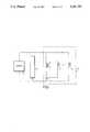
- FIG. 1is a schematic diagram of a preferred embodiment of the invention.
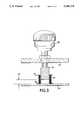
- FIG. 2is a detailed drawing of a variable inductor illustrated in FIG. 1.
- FIG. 3is a detailed drawing of an alternate embodiment of the variable inductor illustrated in FIGS. 1 and 2.
- FIG. 4is an alternative embodiment of the lighting fixture shown in FIG. 1.
- a fluorescent lamp 2power is supplied to a fluorescent lamp 2 from an appropriate power source (not shown) through a standard inverter 4 connected in parallel to lamp 2.
- the intensity of the light emitted from lamp 2is regulated by a control circuit 6 that includes a variable inductor L V and a plurality of standard fixed inductors L 1 -L N .
- a switch 8is adjustable to connect one of the inductors to lamp 2 in parallel.
- a complete lighting fixtureincludes other standard components (filters, etc.) well known to those skilled in the art and therefore not shown in FIG. 1.
- variable inductor L Vis shown in more detail.
- Inductor L Vis supported in a housing 9 and includes a coil 10 having leads 11, 12.
- a ferrite core 13which is secured to the lower part of housing 9 through a base 14 and a screw 15.
- the upper portion of coil 10is attached to a second, movable ferrite core 16 which is positioned above ferrite core 13 with a gap ⁇ Y therebetween.
- Movable ferrite core 16is attached at its upper end to a movable base 17.
- a screw 18is secured to movable base 17, with the head of the screw positioned within a recess 19 in the bottom of a thumbscrew 20.
- Thumbscrew 20is manually rotatable through a bore in housing 9.
- a spring 22surrounds bases 14 and 17 and exerts a force that pulls bases 14 and 17 away from each other. Therefore, when thumbscrew 20 is rotated to move it away from housing 9, the head of screw 18 remains within recess 19 due to the force of spring 26. Ferrite core 16 will therefore also be raised which will increase ⁇ Y, and decrease the inductance measured across leads 11, 12. Conversely, rotating thumbscrew 20 in the opposite direction will reduce ⁇ Y and result in an increase in inductance.
- variable inductor L Vthe intensity of the light emitted by lamp 2 can be varied by varying the inductance of inductor L V through rotation of thumbscrew 20.
- Fixed inductors L 1 -L Nhave different inductances, each of which corresponds to a different desired intensity of the light emitted by lamp 2. For example, L 1 can be chosen so that the light emitted by lamp 2 will be reduced by 20% when switch 8 is adjusted to connect L 1 to lamp 2. Similarly, L 2 can be chosen to reduce the light emitted by lamp 2 by 40%, etc.
- a usercan either choose L V and manually adjust the light intensity to a desired level, or can choose a fixed inductor which sets the light intensity at a predetermined level.
- Switch 8can also be left in an open position which will effectively remove all of the inductors from the circuit causing lamp 2 to emit light at its normal or maximum intensity.
- FIG. 3shows an alternate embodiment of variable inductor L V .
- a coil 30, having leads 31, 32is attached to housing 34.
- a ferrite core 36attached to a thumbscrew 38, can be raised and lowered into the center of coil 30.
- the amount of core 36 within coil 30is represented by ⁇ Y.
- ⁇ YAs ferrite core 36 is lowered into the center of coil 30, ⁇ Y decreases and the inductance measured across leads 31, 32 will increase. Conversely, the inductance can be reduced by raising ferrite core 36 and increasing ⁇ Y.
- FIG. 4shows an alternate embodiment of the lighting fixture shown in FIG. 1.
- a control circuit 40includes a variable capacitor C V and a plurality of fixed capacitors C 1 -C N .
- a switch 42selectively connects one of the capacitors to lamp 2 in parallel.
- the capacitors used in this embodimentare standard, widely available capacitors.
- This embodimentis identical to the embodiment shown in FIG. 1, except variable inductor L V has been replaced with variable capacitor C V , and fixed inductors L 1 -L N have been replaced by fixed capacitors C 1 -C N .
- the embodiments of FIGS. 1 and 4operate in a similar manner, and a detailed discussion of the operation of the embodiment of FIG. 4 is therefore not necessary.
- the use of capacitorswill achieve the same beneficial effects as inductors.
- the dimming control circuits described aboveaccomplish light level control without adversely affecting the stability of the light output.
- the control circuitsuse a minimal amount of power, and allow the lamp to be quickly brought to full power from a low intensity setting.
- any appropriate inductormay be substituted for the inductors described above.
- the manually adjustable inductor described abovecan be servo driven.
- a manually variable capacitorcan be used or one varied by an appropriate servo.
- a control circuitcould also be used that employs a combination of inductors and capacitors. While only one lamp is shown in the illustrative embodiment, the invention can clearly be used to control a plurality of lamps. Furthermore, the invention is not limited to dimming the output of a lamp. It may be used in other applications where it is desirable to control the power supplied to a load.
Landscapes
- Discharge-Lamp Control Circuits And Pulse- Feed Circuits (AREA)
- Coils Or Transformers For Communication (AREA)
Abstract
Description
Claims (62)
Priority Applications (5)
| Application Number | Priority Date | Filing Date | Title |
|---|---|---|---|
| US07/484,112US5140228A (en) | 1990-02-23 | 1990-02-23 | Apparatus for regulating the intensity of light emitted by a lamp |
| EP19910905982EP0516752A4 (en) | 1990-02-23 | 1991-02-25 | Apparatus for regulating the intensity of light emitted by a lamp |
| JP91506075AJPH05506955A (en) | 1990-02-23 | 1991-02-25 | A device that adjusts the density of light emitted by a lamp |
| PCT/US1991/001329WO1991013530A1 (en) | 1990-02-23 | 1991-02-25 | Apparatus for regulating the intensity of light emitted by a lamp |
| US07/891,421US5347257A (en) | 1990-02-23 | 1992-05-29 | Varying inductances |
Applications Claiming Priority (1)
| Application Number | Priority Date | Filing Date | Title |
|---|---|---|---|
| US07/484,112US5140228A (en) | 1990-02-23 | 1990-02-23 | Apparatus for regulating the intensity of light emitted by a lamp |
Related Child Applications (1)
| Application Number | Title | Priority Date | Filing Date |
|---|---|---|---|
| US07/891,421Continuation-In-PartUS5347257A (en) | 1990-02-23 | 1992-05-29 | Varying inductances |
Publications (1)
| Publication Number | Publication Date |
|---|---|
| US5140228Atrue US5140228A (en) | 1992-08-18 |
Family
ID=23922792
Family Applications (2)
| Application Number | Title | Priority Date | Filing Date |
|---|---|---|---|
| US07/484,112Expired - Fee RelatedUS5140228A (en) | 1990-02-23 | 1990-02-23 | Apparatus for regulating the intensity of light emitted by a lamp |
| US07/891,421Expired - Fee RelatedUS5347257A (en) | 1990-02-23 | 1992-05-29 | Varying inductances |
Family Applications After (1)
| Application Number | Title | Priority Date | Filing Date |
|---|---|---|---|
| US07/891,421Expired - Fee RelatedUS5347257A (en) | 1990-02-23 | 1992-05-29 | Varying inductances |
Country Status (4)
| Country | Link |
|---|---|
| US (2) | US5140228A (en) |
| EP (1) | EP0516752A4 (en) |
| JP (1) | JPH05506955A (en) |
| WO (1) | WO1991013530A1 (en) |
Cited By (14)
| Publication number | Priority date | Publication date | Assignee | Title |
|---|---|---|---|---|
| US5373215A (en)* | 1993-07-07 | 1994-12-13 | The United States Of America As Represented By The United States Department Of Energy | Ionization tube simmer current circuit |
| US5758644A (en)* | 1995-06-07 | 1998-06-02 | Masimo Corporation | Manual and automatic probe calibration |
| US6593705B1 (en) | 2000-01-07 | 2003-07-15 | Cyberoptics Corporation | Rapid-firing flashlamp discharge circuit |
| US7245953B1 (en) | 1999-04-12 | 2007-07-17 | Masimo Corporation | Reusable pulse oximeter probe and disposable bandage apparatii |
| US7272425B2 (en) | 1999-12-09 | 2007-09-18 | Masimo Corporation | Pulse oximetry sensor including stored sensor data |
| US20070282478A1 (en)* | 2006-06-05 | 2007-12-06 | Ammar Al-Ali | Parameter upgrade system |
| USRE41317E1 (en) | 1998-10-15 | 2010-05-04 | Masimo Corporation | Universal modular pulse oximeter probe for use with reusable and disposable patient attachment devices |
| USRE41912E1 (en) | 1998-10-15 | 2010-11-02 | Masimo Corporation | Reusable pulse oximeter probe and disposable bandage apparatus |
| US7990382B2 (en) | 2006-01-03 | 2011-08-02 | Masimo Corporation | Virtual display |
| DE102011111067A1 (en)* | 2011-08-24 | 2013-02-28 | Klaus Wammes | Low pressure plasma light source |
| US8989831B2 (en) | 2009-05-19 | 2015-03-24 | Masimo Corporation | Disposable components for reusable physiological sensor |
| US9560998B2 (en) | 2006-10-12 | 2017-02-07 | Masimo Corporation | System and method for monitoring the life of a physiological sensor |
| US9795739B2 (en) | 2009-05-20 | 2017-10-24 | Masimo Corporation | Hemoglobin display and patient treatment |
| US10058275B2 (en) | 2003-07-25 | 2018-08-28 | Masimo Corporation | Multipurpose sensor port |
Families Citing this family (8)
| Publication number | Priority date | Publication date | Assignee | Title |
|---|---|---|---|---|
| US5140228A (en)* | 1990-02-23 | 1992-08-18 | Stocker & Yale, Inc. | Apparatus for regulating the intensity of light emitted by a lamp |
| US5345150A (en)* | 1992-03-26 | 1994-09-06 | Stocker & Yale, Inc. | Regulating light intensity by means of magnetic core with multiple windings |
| GB9715992D0 (en) | 1997-07-29 | 1997-10-01 | Limpkin Alan | Variable high frequency controllers and systems |
| US6181082B1 (en)* | 1998-10-15 | 2001-01-30 | Electro-Mag International, Inc. | Ballast power control circuit |
| US5999077A (en)* | 1998-12-10 | 1999-12-07 | The United States Of America As Represented By The Secretary Of The Navy | Voltage controlled variable inductor |
| US20040032315A1 (en)* | 2002-08-19 | 2004-02-19 | Lewis Illingworth | Variable inductor responsive to AC current level |
| EP3282304B1 (en)* | 2016-08-08 | 2023-10-04 | Essilor International | Ophthalmic device; method for powering an ophthalmic device |
| CN107424724B (en)* | 2017-09-14 | 2019-03-15 | 湖北绍新特种电气股份有限公司 | A kind of full-shield high frequency controllable impedance |
Citations (17)
| Publication number | Priority date | Publication date | Assignee | Title |
|---|---|---|---|---|
| US380945A (en)* | 1888-04-10 | Adjustable inductive resistance | ||
| DE1224837B (en)* | 1965-02-23 | 1966-09-15 | Trilux Lenze Gmbh & Co Kg | Luminaire with several fluorescent lamps that can be operated in several brightness levels |
| US3551799A (en)* | 1968-03-23 | 1970-12-29 | Licentia Gmbh | Mains voltage stabilizing apparatus providing constant reactive current |
| US3919592A (en)* | 1973-11-19 | 1975-11-11 | Lutron Electronics Co | High intensity discharge mercury vapor lamp dimming system |
| US3936696A (en)* | 1973-08-27 | 1976-02-03 | Lutron Electronics Co., Inc. | Dimming circuit with saturated semiconductor device |
| US4127795A (en)* | 1977-08-19 | 1978-11-28 | Gte Sylvania Incorporated | Lamp ballast circuit |
| US4162428A (en)* | 1978-06-29 | 1979-07-24 | Westinghouse Electric Corp. | Variable inductance ballast apparatus for HID lamp |
| US4162429A (en)* | 1977-03-11 | 1979-07-24 | Westinghouse Electric Corp. | Ballast circuit for accurately regulating HID lamp wattage |
| US4350934A (en)* | 1980-07-23 | 1982-09-21 | Westinghouse Electric Corp. | Discharge device ballast component which provides both voltage transformation and variable inductive reactance |
| US4441054A (en)* | 1982-04-12 | 1984-04-03 | Gte Products Corporation | Stabilized dimming circuit for lamp ballasts |
| US4443740A (en)* | 1982-04-09 | 1984-04-17 | Goralnik Charles D | Dimmer switch for a fluorescent lamp |
| US4559479A (en)* | 1983-06-20 | 1985-12-17 | Emerson Electric Co. | Starting and dimming circuit for fluorescent lamps |
| US4562384A (en)* | 1983-04-19 | 1985-12-31 | General Electric Company | Variable reactance inductor with adjustable ranges |
| US4864482A (en)* | 1988-07-07 | 1989-09-05 | Etta Industries, Inc. | Conversion circuit for limiting inrush current |
| US4933605A (en)* | 1987-06-12 | 1990-06-12 | Etta Industries, Inc. | Fluorescent dimming ballast utilizing a resonant sine wave power converter |
| US4943886A (en)* | 1989-02-10 | 1990-07-24 | Etta Industries, Inc. | Circuitry for limiting current between power inverter output terminals and ground |
| WO1990009727A1 (en)* | 1989-02-14 | 1990-08-23 | Ulrich Behringer | Process and device for tonal processing |
Family Cites Families (26)
| Publication number | Priority date | Publication date | Assignee | Title |
|---|---|---|---|---|
| GB417378A (en)* | 1933-02-01 | 1934-10-01 | Gen Electric Co Ltd | Improvements in inductance coils |
| GB442849A (en)* | 1934-05-11 | 1936-02-17 | Ericsson Telefon Ab L M | Improvements in inductance coils |
| FR910271A (en)* | 1944-11-14 | 1946-06-03 | Le Materiel Ondia | Refinements to split iron core chokes |
| US2460656A (en)* | 1945-09-10 | 1949-02-01 | Jefferson Electric Co | Adjustable magnetic shunt for laminated core structures |
| US2448296A (en)* | 1946-01-29 | 1948-08-31 | Us Sec War | Tunable inductance |
| US2471222A (en)* | 1947-11-07 | 1949-05-24 | Lorant Lionel | Regulated transformer |
| US2617092A (en)* | 1949-09-08 | 1952-11-04 | Gen Electric | Differential screw adjustment for magnetic core air gaps |
| FR1081165A (en)* | 1953-04-23 | 1954-12-16 | Lignes Telegraph Telephon | Ferromagnetic Core Inductance Coils |
| FR1085135A (en)* | 1953-06-19 | 1955-01-27 | Lignes Telegraph Telephon | Adjustable Inductance Ferromagnetic Core Coil |
| US2823359A (en)* | 1954-06-01 | 1958-02-11 | Rca Corp | Miniature intermediate-frequency transformer |
| US2855571A (en)* | 1955-11-22 | 1958-10-07 | Hazeltine Research Inc | Inductance device |
| US3082388A (en)* | 1956-01-03 | 1963-03-19 | Sperry Rand Corp | Electromagnetic signal generator |
| FR1175256A (en)* | 1957-05-16 | 1959-03-23 | Csf | Self-inductance adjustable coils |
| US2935707A (en)* | 1958-05-12 | 1960-05-03 | Emerson Radio & Phonograph Cor | Inductive tuning device |
| GB966936A (en)* | 1962-07-11 | 1964-08-19 | Standard Telephones Cables Ltd | Adjustable inductor |
| US3289042A (en)* | 1963-01-24 | 1966-11-29 | Ite Circuit Breaker Ltd | Current limiting device |
| CH418418A (en)* | 1963-10-10 | 1966-08-15 | Matter Paul | Two-part pot core with an air gap that can be changed for the purpose of inductance adjustment |
| DE1514133A1 (en)* | 1965-04-08 | 1969-05-08 | Heinz Litz | Magnetic core with adjustable air gap |
| GB1106927A (en)* | 1965-04-20 | 1968-03-20 | Frederick Arthur Summerlin | Synchro |
| DE1564621C3 (en)* | 1966-06-03 | 1975-05-28 | Siemens Ag, 1000 Berlin Und 8000 Muenchen | Adjustable pot core for telecommunications coils |
| US3423702A (en)* | 1966-12-01 | 1969-01-21 | Alfred Electronics | Compressionally-loaded spring forming dc connection between the outer and inner conductor of a tem-mode transmission line |
| US3753178A (en)* | 1971-06-03 | 1973-08-14 | Nippon Denso Co | Relay for voltage regulator |
| DE2209071A1 (en)* | 1972-02-25 | 1973-08-30 | Siemens Ag | ADJUSTABLE ELECTRIC COIL, IN PARTICULAR FOR HYBRID AND PRINTED CIRCUITS |
| DE3224997A1 (en)* | 1982-07-03 | 1984-01-05 | Heinz-Dieter 6000 Frankfurt Schröder | Current regulation of fluorescent tubes |
| US4551699A (en)* | 1983-06-22 | 1985-11-05 | Sperry Corporation | Rotary variable differential transformer |
| US5140228A (en)* | 1990-02-23 | 1992-08-18 | Stocker & Yale, Inc. | Apparatus for regulating the intensity of light emitted by a lamp |
- 1990
- 1990-02-23USUS07/484,112patent/US5140228A/ennot_activeExpired - Fee Related
- 1991
- 1991-02-25JPJP91506075Apatent/JPH05506955A/enactivePending
- 1991-02-25WOPCT/US1991/001329patent/WO1991013530A1/ennot_activeApplication Discontinuation
- 1991-02-25EPEP19910905982patent/EP0516752A4/ennot_activeWithdrawn
- 1992
- 1992-05-29USUS07/891,421patent/US5347257A/ennot_activeExpired - Fee Related
Patent Citations (17)
| Publication number | Priority date | Publication date | Assignee | Title |
|---|---|---|---|---|
| US380945A (en)* | 1888-04-10 | Adjustable inductive resistance | ||
| DE1224837B (en)* | 1965-02-23 | 1966-09-15 | Trilux Lenze Gmbh & Co Kg | Luminaire with several fluorescent lamps that can be operated in several brightness levels |
| US3551799A (en)* | 1968-03-23 | 1970-12-29 | Licentia Gmbh | Mains voltage stabilizing apparatus providing constant reactive current |
| US3936696A (en)* | 1973-08-27 | 1976-02-03 | Lutron Electronics Co., Inc. | Dimming circuit with saturated semiconductor device |
| US3919592A (en)* | 1973-11-19 | 1975-11-11 | Lutron Electronics Co | High intensity discharge mercury vapor lamp dimming system |
| US4162429A (en)* | 1977-03-11 | 1979-07-24 | Westinghouse Electric Corp. | Ballast circuit for accurately regulating HID lamp wattage |
| US4127795A (en)* | 1977-08-19 | 1978-11-28 | Gte Sylvania Incorporated | Lamp ballast circuit |
| US4162428A (en)* | 1978-06-29 | 1979-07-24 | Westinghouse Electric Corp. | Variable inductance ballast apparatus for HID lamp |
| US4350934A (en)* | 1980-07-23 | 1982-09-21 | Westinghouse Electric Corp. | Discharge device ballast component which provides both voltage transformation and variable inductive reactance |
| US4443740A (en)* | 1982-04-09 | 1984-04-17 | Goralnik Charles D | Dimmer switch for a fluorescent lamp |
| US4441054A (en)* | 1982-04-12 | 1984-04-03 | Gte Products Corporation | Stabilized dimming circuit for lamp ballasts |
| US4562384A (en)* | 1983-04-19 | 1985-12-31 | General Electric Company | Variable reactance inductor with adjustable ranges |
| US4559479A (en)* | 1983-06-20 | 1985-12-17 | Emerson Electric Co. | Starting and dimming circuit for fluorescent lamps |
| US4933605A (en)* | 1987-06-12 | 1990-06-12 | Etta Industries, Inc. | Fluorescent dimming ballast utilizing a resonant sine wave power converter |
| US4864482A (en)* | 1988-07-07 | 1989-09-05 | Etta Industries, Inc. | Conversion circuit for limiting inrush current |
| US4943886A (en)* | 1989-02-10 | 1990-07-24 | Etta Industries, Inc. | Circuitry for limiting current between power inverter output terminals and ground |
| WO1990009727A1 (en)* | 1989-02-14 | 1990-08-23 | Ulrich Behringer | Process and device for tonal processing |
Cited By (45)
| Publication number | Priority date | Publication date | Assignee | Title |
|---|---|---|---|---|
| US5373215A (en)* | 1993-07-07 | 1994-12-13 | The United States Of America As Represented By The United States Department Of Energy | Ionization tube simmer current circuit |
| US7496391B2 (en) | 1995-06-07 | 2009-02-24 | Masimo Corporation | Manual and automatic probe calibration |
| US5758644A (en)* | 1995-06-07 | 1998-06-02 | Masimo Corporation | Manual and automatic probe calibration |
| US6011986A (en)* | 1995-06-07 | 2000-01-04 | Masimo Corporation | Manual and automatic probe calibration |
| US6397091B2 (en) | 1995-06-07 | 2002-05-28 | Masimo Corporation | Manual and automatic probe calibration |
| US8781543B2 (en) | 1995-06-07 | 2014-07-15 | Jpmorgan Chase Bank, National Association | Manual and automatic probe calibration |
| US6678543B2 (en) | 1995-06-07 | 2004-01-13 | Masimo Corporation | Optical probe and positioning wrap |
| US8145287B2 (en) | 1995-06-07 | 2012-03-27 | Masimo Corporation | Manual and automatic probe calibration |
| US7526328B2 (en) | 1995-06-07 | 2009-04-28 | Masimo Corporation | Manual and automatic probe calibration |
| USRE41317E1 (en) | 1998-10-15 | 2010-05-04 | Masimo Corporation | Universal modular pulse oximeter probe for use with reusable and disposable patient attachment devices |
| USRE44823E1 (en) | 1998-10-15 | 2014-04-01 | Masimo Corporation | Universal modular pulse oximeter probe for use with reusable and disposable patient attachment devices |
| USRE41912E1 (en) | 1998-10-15 | 2010-11-02 | Masimo Corporation | Reusable pulse oximeter probe and disposable bandage apparatus |
| US8706179B2 (en) | 1998-10-15 | 2014-04-22 | Masimo Corporation | Reusable pulse oximeter probe and disposable bandage apparatii |
| USRE43169E1 (en) | 1998-10-15 | 2012-02-07 | Masimo Corporation | Universal modular pulse oximeter probe for use with reusable and disposable patient attachment devices |
| USRE43860E1 (en) | 1998-10-15 | 2012-12-11 | Masimo Corporation | Reusable pulse oximeter probe and disposable bandage apparatus |
| US7245953B1 (en) | 1999-04-12 | 2007-07-17 | Masimo Corporation | Reusable pulse oximeter probe and disposable bandage apparatii |
| US8175672B2 (en) | 1999-04-12 | 2012-05-08 | Masimo Corporation | Reusable pulse oximeter probe and disposable bandage apparatii |
| US7272425B2 (en) | 1999-12-09 | 2007-09-18 | Masimo Corporation | Pulse oximetry sensor including stored sensor data |
| US6593705B1 (en) | 2000-01-07 | 2003-07-15 | Cyberoptics Corporation | Rapid-firing flashlamp discharge circuit |
| US11020029B2 (en) | 2003-07-25 | 2021-06-01 | Masimo Corporation | Multipurpose sensor port |
| US10058275B2 (en) | 2003-07-25 | 2018-08-28 | Masimo Corporation | Multipurpose sensor port |
| US7990382B2 (en) | 2006-01-03 | 2011-08-02 | Masimo Corporation | Virtual display |
| US11191485B2 (en) | 2006-06-05 | 2021-12-07 | Masimo Corporation | Parameter upgrade system |
| US20070282478A1 (en)* | 2006-06-05 | 2007-12-06 | Ammar Al-Ali | Parameter upgrade system |
| US10188348B2 (en) | 2006-06-05 | 2019-01-29 | Masimo Corporation | Parameter upgrade system |
| US12109048B2 (en) | 2006-06-05 | 2024-10-08 | Masimo Corporation | Parameter upgrade system |
| US9560998B2 (en) | 2006-10-12 | 2017-02-07 | Masimo Corporation | System and method for monitoring the life of a physiological sensor |
| US10039482B2 (en) | 2006-10-12 | 2018-08-07 | Masimo Corporation | System and method for monitoring the life of a physiological sensor |
| US10342470B2 (en) | 2006-10-12 | 2019-07-09 | Masimo Corporation | System and method for monitoring the life of a physiological sensor |
| US11857319B2 (en) | 2006-10-12 | 2024-01-02 | Masimo Corporation | System and method for monitoring the life of a physiological sensor |
| US10863938B2 (en) | 2006-10-12 | 2020-12-15 | Masimo Corporation | System and method for monitoring the life of a physiological sensor |
| US12127835B2 (en) | 2006-10-12 | 2024-10-29 | Masimo Corporation | System and method for monitoring the life of a physiological sensor |
| US11317837B2 (en) | 2006-10-12 | 2022-05-03 | Masimo Corporation | System and method for monitoring the life of a physiological sensor |
| US9895107B2 (en) | 2009-05-19 | 2018-02-20 | Masimo Corporation | Disposable components for reusable physiological sensor |
| US11331042B2 (en) | 2009-05-19 | 2022-05-17 | Masimo Corporation | Disposable components for reusable physiological sensor |
| US10342487B2 (en) | 2009-05-19 | 2019-07-09 | Masimo Corporation | Disposable components for reusable physiological sensor |
| US8989831B2 (en) | 2009-05-19 | 2015-03-24 | Masimo Corporation | Disposable components for reusable physiological sensor |
| US12408869B2 (en) | 2009-05-19 | 2025-09-09 | Masimo Corporation | Disposable components for reusable physiological sensor |
| US10953156B2 (en) | 2009-05-20 | 2021-03-23 | Masimo Corporation | Hemoglobin display and patient treatment |
| US11752262B2 (en) | 2009-05-20 | 2023-09-12 | Masimo Corporation | Hemoglobin display and patient treatment |
| US10413666B2 (en) | 2009-05-20 | 2019-09-17 | Masimo Corporation | Hemoglobin display and patient treatment |
| US9795739B2 (en) | 2009-05-20 | 2017-10-24 | Masimo Corporation | Hemoglobin display and patient treatment |
| US12318580B2 (en) | 2009-05-20 | 2025-06-03 | Masimo Corporation | Hemoglobin display and patient treatment |
| DE102011111067B4 (en)* | 2011-08-24 | 2013-04-04 | Klaus Wammes | Low pressure plasma light source |
| DE102011111067A1 (en)* | 2011-08-24 | 2013-02-28 | Klaus Wammes | Low pressure plasma light source |
Also Published As
| Publication number | Publication date |
|---|---|
| JPH05506955A (en) | 1993-10-07 |
| WO1991013530A1 (en) | 1991-09-05 |
| EP0516752A1 (en) | 1992-12-09 |
| US5347257A (en) | 1994-09-13 |
| EP0516752A4 (en) | 1993-11-18 |
Similar Documents
| Publication | Publication Date | Title |
|---|---|---|
| US5140228A (en) | Apparatus for regulating the intensity of light emitted by a lamp | |
| US5581158A (en) | Lamp brightness control circuit with ambient light compensation | |
| US9961735B2 (en) | LED constant-voltage dimming power supply and dimming system for LED lamp having same | |
| US4712045A (en) | Electric arrangement for regulating the luminous intensity of at least one discharge lamp | |
| US4988920A (en) | High-frequency power circuit for gas discharge lamps | |
| US10874008B2 (en) | Dim to warm controller for LEDs | |
| US4482844A (en) | Lamp dimmer | |
| US6628089B2 (en) | Extraction of accessory power from a signal supplied to a luminaire from a phase angle dimmer | |
| US4527099A (en) | Control circuit for gas discharge lamps | |
| KR20010085532A (en) | Dual control dimming ballast | |
| FI73114B (en) | KOPPLINGSANORDNING FOER ATT DRIVA LAOGTRYCKSURLADDNINGSLAMPOR, VILKEN ANORDNING HAR EN REGLERBAR LJUSSTROEM. | |
| US5262701A (en) | Circuit arrangement for operating a high pressure sodium lamp | |
| CA2029434A1 (en) | Integrated power level control and on/off function circuit | |
| US6577075B2 (en) | High intensity discharge lamp magnetic/electronic ballast | |
| JPH01137599A (en) | Apparatus and method of luminance control fluorescent ligting and fluorescent lamp dimming | |
| US5028862A (en) | Voltage follower circuit for use in power level control circuits | |
| US4937502A (en) | Electronic ballast | |
| WO1993009649A1 (en) | Lamp brightness control circuit with ambient light compensation | |
| US5757142A (en) | Fluorescent light dimmer | |
| CA1266879A (en) | Circuit arrangement for operating a high-pressure sodium discharge lamp | |
| EP1356714B1 (en) | Ballast and method of feeding a fluorescent lamp | |
| US11229097B2 (en) | Method and apparatus for adjusting the rate of change of the brightness of a light emitting diode (LED) light fixture | |
| JPH113787A (en) | Dimmer for illumination | |
| GB2121248A (en) | Capacitive voltage dropper | |
| JP2025067721A (en) | Led bulb, dimming control device, and dimming control method |
Legal Events
| Date | Code | Title | Description |
|---|---|---|---|
| AS | Assignment | Owner name:STOCKER & YALE, A CORP. OF MA., MASSACHUSETTS Free format text:ASSIGNMENT OF ASSIGNORS INTEREST.;ASSIGNOR:BIEGEL, GEORGE E.;REEL/FRAME:005305/0849 Effective date:19900406 | |
| AS | Assignment | Owner name:FIRST NATIONAL BANK OF BOSTON, THE, MASSACHUSETTS Free format text:SECURITY INTEREST;ASSIGNOR:STOCKER & YALE, INC.;REEL/FRAME:006522/0242 Effective date:19930305 | |
| CC | Certificate of correction | ||
| AS | Assignment | Owner name:STOCKER & YALE, INC., MASSACHUSETTS Free format text:RELEASE BY SECURED PARTY;ASSIGNOR:FIRST NATIONAL BANK OF BOSTON, THE;REEL/FRAME:007505/0029 Effective date:19950522 | |
| FPAY | Fee payment | Year of fee payment:4 | |
| AS | Assignment | Owner name:SHAWMUT BANK, N.A., MASSACHUSETTS Free format text:SECURITY AGREEMENT;ASSIGNOR:STOCKER & YALE INC.;REEL/FRAME:007969/0874 Effective date:19960306 | |
| AS | Assignment | Owner name:NORWEST BUSINESS CREDIT, INC., MASSACHUSETTS Free format text:SECURITY INTEREST;ASSIGNOR:STOCKER & YALE, INC.;REEL/FRAME:009817/0940 Effective date:19990211 Owner name:STOCKER & YALE, INC., A MASSACHUSETTS CORPORATION, Free format text:ASSIGNMENT OF ASSIGNORS INTEREST;ASSIGNOR:FLEET NATIONAL BANK;REEL/FRAME:009817/0935 Effective date:19990211 | |
| REMI | Maintenance fee reminder mailed | ||
| LAPS | Lapse for failure to pay maintenance fees | ||
| FP | Lapsed due to failure to pay maintenance fee | Effective date:20000818 | |
| STCH | Information on status: patent discontinuation | Free format text:PATENT EXPIRED DUE TO NONPAYMENT OF MAINTENANCE FEES UNDER 37 CFR 1.362 |