US5140198A - Image canceling mixer circuit on an integrated circuit chip - Google Patents
Image canceling mixer circuit on an integrated circuit chipDownload PDFInfo
- Publication number
- US5140198A US5140198AUS07/400,186US40018689AUS5140198AUS 5140198 AUS5140198 AUS 5140198AUS 40018689 AUS40018689 AUS 40018689AUS 5140198 AUS5140198 AUS 5140198A
- Authority
- US
- United States
- Prior art keywords
- phase
- circuit
- signal
- mixer
- emitter
- Prior art date
- Legal status (The legal status is an assumption and is not a legal conclusion. Google has not performed a legal analysis and makes no representation as to the accuracy of the status listed.)
- Expired - Lifetime
Links
Images


Classifications
- H—ELECTRICITY
- H04—ELECTRIC COMMUNICATION TECHNIQUE
- H04B—TRANSMISSION
- H04B1/00—Details of transmission systems, not covered by a single one of groups H04B3/00 - H04B13/00; Details of transmission systems not characterised by the medium used for transmission
- H04B1/06—Receivers
- H04B1/10—Means associated with receiver for limiting or suppressing noise or interference
- H04B1/12—Neutralising, balancing, or compensation arrangements
- H04B1/123—Neutralising, balancing, or compensation arrangements using adaptive balancing or compensation means
- H—ELECTRICITY
- H03—ELECTRONIC CIRCUITRY
- H03D—DEMODULATION OR TRANSFERENCE OF MODULATION FROM ONE CARRIER TO ANOTHER
- H03D7/00—Transference of modulation from one carrier to another, e.g. frequency-changing
- H03D7/16—Multiple-frequency-changing
- H03D7/165—Multiple-frequency-changing at least two frequency changers being located in different paths, e.g. in two paths with carriers in quadrature
- H03D7/166—Multiple-frequency-changing at least two frequency changers being located in different paths, e.g. in two paths with carriers in quadrature using two or more quadrature frequency translation stages
- H—ELECTRICITY
- H03—ELECTRONIC CIRCUITRY
- H03D—DEMODULATION OR TRANSFERENCE OF MODULATION FROM ONE CARRIER TO ANOTHER
- H03D7/00—Transference of modulation from one carrier to another, e.g. frequency-changing
- H03D7/18—Modifications of frequency-changers for eliminating image frequencies
Definitions
- This inventionrelates generally to telecommunications and particularly to an integrated circuit frequency conversion circuit.
- Copending patent application Ser. No. 07/213,719 filed June 30, 1988 by Lawrence H. Ragan and entitled Wristwatch Receiver Architecturedescribes an FM radio receiver suitable for paging applications, and constructed on a single integrated circuit chip having only a small number of off-chip components. It is desirable to minimize the number of discrete, off-chip components because it reduces the cost of the unit, provides additional space in the package formerly occupied by the discrete components, and makes the device less labor-intensive to assemble.
- a mixer circuit in a receivertranslates a signal received at one frequency to another frequency, termed an intermediate frequency (IF), at which the signal can be processed more conveniently and effectively.
- IFintermediate frequency
- the intermediate frequencyfacilitates processing, filtering and detecting a signal with greater ease and efficiency than would be possible were the signal kept at the radio frequency at which it was transmitted and propagated.
- a problem inherent in all mixer circuitsis generation of image frequency signals. When two signals are mixed, signal components are produced at the sum and difference of the two signal frequencies and at the harmonics of the frequencies. It is desirable to reduce or eliminate the image-frequency response of the mixer circuit, however it is often impractical to filter out the image frequency. Post-mixer filtering has been found to be inadequate because input signal images can be mixed to the same intermediate frequency as the desired signal.
- Image-rejection mixer circuits utilizing phase-shifting techniquesare known, however such circuits have heretofore used transmission lines, operational amplifiers or L-C networks, none of which are conducive to implementation in a singlechip integrated circuit receiver.
- a single-chip integrated circuit radio receiverwhich is designed for use in a radio paging system, includes an improved on-chip image-rejection mixer circuit.
- An amplified, wide-band RF input signalis split and applied to inputs of first and second doubly balanced mixers, while a local oscillator signal is injected into the first mixer in phase, and shifted in phase by 90° into the second mixer.
- the quadrature outputs of the second mixerare applied to a balanced phase shift element where the signals are shifted an additional 90°, and then combined with the outputs of the in-phase mixer, the summation of these signals canceling the image frequency while reinforcing the desired signal.
- the balanced 90° phase shift elementemploys transistors each having a diode-connected transistor in series with the collector load resistor, and a collector-to-base capacitor, which provide a constant-amplitude phase shift in a unity gain structure independent of current, with equal emitter and collector resistances.
- Emitter currentis adjustable to produce a precise 90° phase shift. The adjustment compensates for production variation in the absolute value of the fixed resistance by varying the current in the transistor and diode, whereby the dynamic resistance offsets the fixed resistance variation.
- the improved mixer circuithas a conversion gain at the desired signal frequency of approximately 7 dB.
- FIG. 1is a block diagram of an improved image-rejecting mixer circuit in accordance with the instant invention
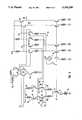
- FIGS. 2 and 3taken together, are a schematic diagram of the circuit of FIG. 1;
- FIG. 4is an idealized representation of the 90° phase shift circuit of FIG. 2.
- FIG. 1shows an image-rejecting mixer circuit 10 having an input buffer 12 receiving an amplified, broad-band radio frequency (RF) signal, suitably in the FM broadcast band, 88-108 megahertz, on an input node 14 from a receiver RF stage (not shown).
- RFradio frequency
- the buffered RF signalsplit in a conventional manner, is applied respectively by way of buses 16, 18 to the low-level signal inputs of doubly-balanced mixers 22, 24.
- a frequency synthesizer 26assuming high-side injection, tunes the 98.7 to 118.7 megahertz range in response to frequency control signal 28 to yield an IF of 10.7 megahertz.
- a local-oscillator (LO) 29 operating in the 240 megahertz rangegenerates an in-phase signal from a conventional divide-by-two frequency divider circuit (not shown), which is applied via bus 30 to the high-level signal input of the mixer 22.
- phase of the LO signalis shifted 90° in phase-shift circuit 32 and applied by way of bus 34 to the high-level input of the mixer 24.
- a precise 90° phase shiftis obtained by utilizing the quadrature output logically derived from an exclusive OR of the fundamental output of the local oscillator 29 and the divide-by-two frequency divider circuit.
- the output signals of the in-phase mixer 22are applied through a level shift and inverter circuit 36 to a summing circuit 40, while the output signals of the 90° mixer 24 are applied to a phase shift circuit 42, where they are inverted and shifted in phase an additional 90°, then applied to the summing circuit 40.
- Phase difference of the signalsis preserved in the frequency transformation of the mixers 22, 24, so that the IF components output have the same phase relationships as the original LO input terms, i.e., the signals output from the in-phase mixer 22 at node 44 undergo no phase shift and are downconverted in the conventional manner, while the signals output from the 90° mixer 24 at node 46 undergo a 90° delay relative to those at the node 44.
- the input buffer 1 and the in-phase mixer 22which is a conventional integrated circuit doubly balanced mixer, receives the low-level RF signals from the input buffers 12 into the bases of transistors 50, 51, the high-level, in-phase LO signals being injected into the bases of transistors 52-55.
- Mixer 22 output signals I 1 , I 2 and mixer 24 output signals D 1 , D 2are applied to level shifting circuits 58, which are emitter-follower transistors.
- Current regulating transistors 60provide impedance matching between the mixers 22, 24, and the respective circuits 36, 42.
- Phase shifter circuit 42comprises two balanced circuits receiving the balanced output signals D 1 , D 2 from the mixer 24 and input respectively to the bases of transistors 61, 62.
- the collectors of transistors 61, 62are connected through respective diode-connected transistors 63, 64 and 500 ohm emitter resistors 65, 66 to voltage supply V CC .
- Balanced MOS capacitors 67, 68are connected respectively between the emitter and base of transistors 61, 62, and 500 ohm resistors 69, 70 are connected respectively between the emitters of transistors 61, 62 and the collector of a current-source transistor 71.
- the circuit 42provides an all-pass filter transfer function for the differential voltage between base nodes 72, 73 to the output differential voltage at output nodes 74, 75.
- the circuit 42has a nominal unity gain transfer function with a phase shift equal to -2 arctan (R'C), where R' is R+(KT/I c q), and I c is quiescent collector current.
- R'C-2 arctan
- I cquiescent collector current
- V o(I cap -V E /R) ⁇ R
- V o :I cap R -V in
- V o(V in -Vo) ⁇ C ⁇ S ⁇ R-V in , where C ⁇ S is admittance;
- V oV in [(-1+R ⁇ C ⁇ S)/(1+R ⁇ C ⁇ S)]
- V o-[(1-R ⁇ C ⁇ S)/(1+R ⁇ C ⁇ S) ⁇ V.sub.in
- the aboveis a one-pole, all pass filter function.
- diode-connected transistors 63, 64The function of diode-connected transistors 63, 64 is to achieve a collector load resistance equal to the emitter resistance plus dynamic emitter resistance, thereby obtaining a unity gain characteristic.
- the emitter currentis variable by way of an external resistor 76 connected to a bonding pad 77 of the integrated circuit chip.
- the emitter current source transistor 71mirrors a circuit 78 which is a proportional-to-absolute-temperature (PTAT) bias current source; therefore, the incremental resistance of the diodes 63, 64 is maintained over a temperature range, providing a stable resistance and time constant as a function of temperature. Since the collector load tracks the emitter load as current is varied, unity gain is preserved and only the phase is varied.
- PTATproportional-to-absolute-temperature
- the level shift and inverter circuit 36provides a gain block for the in-phase signals I 1 , I 2 of mixer 22 input respectively by way of output nodes 79, 80 of the level shifting circuit 58.
- the circuit 36adjusts for losses in the signal path.
- the summing circuit 40sums the in-phase signals from nodes 81, 82 and the out-of-phase signals from nodes 74, 75, injected, respectively, into the bases of transistors 84-87, the summation occurring at nodes 90, 92 where the collector currents, respectively, of transistors 84, 86 and 85, 87 are added together.
- Output signals at the nodes 90, 92are driven into the bases, respectively, of balancing transistor 94 and output transistor 95 of output circuit 96, which provides an output signal at a node 98 to a single ended filter stage (not shown).
- the delay of the D 2 signal output from node 99 of the mixer 24is manifest by a negative 90° phase shift in the positive frequency components and a positive 90° phase shift in the negative frequency components.
- the IF components from the upper sideband termshave been shifted 180° and the lower sideband terms again remain unchanged.
- the D 2 and I 2 signalsare summed at node 92 in the summing circuit 40, the upper sideband components cancel and the unshifted lower sideband terms remain.
- the other output at the node 90contains the desired upper sideband terms of the IF signal.
- the mixer circuitthus, by virtue of its symmetry and internal balance, reinforces the desired signal and suppresses and substantially attenuates harmonic and image frequency products. Efficient phase cancellation is achieved through the ability to maintain extremely accurate phase angles.
- the initial 90° phase shiftis derived digitally in a frequency synthesizer circuit, while the phase shift circuit 42 provides a constant-amplitude phase shift in a unity gain structure independent of current, with equal emitter and collector resistances, the emitter current being adjustable to produce the second, precise 90° phase shift.
- the adjustmentcompensates for production variation in the absolute value of the fixed resistance by varying the current in the transistors 61, 62 and diodes 63, 64, whereby the dynamic resistance offsets production variation of the fixed resistance.
Landscapes
- Engineering & Computer Science (AREA)
- Computer Networks & Wireless Communication (AREA)
- Signal Processing (AREA)
- Power Engineering (AREA)
- Networks Using Active Elements (AREA)
- Superheterodyne Receivers (AREA)
- Solid State Image Pick-Up Elements (AREA)
- Semiconductor Integrated Circuits (AREA)
Abstract
Description
I.sub.R :=V.sub.E /R
and
Vo:=(I.sub.cap -I.sub.R)·R
Claims (5)
Priority Applications (8)
| Application Number | Priority Date | Filing Date | Title |
|---|---|---|---|
| US07/400,186US5140198A (en) | 1989-08-30 | 1989-08-30 | Image canceling mixer circuit on an integrated circuit chip |
| JP2511136AJP2994458B2 (en) | 1989-08-30 | 1990-07-30 | Image removal mixer circuit on integrated circuit chip |
| EP90911420AEP0489749B1 (en) | 1989-08-30 | 1990-07-30 | Image canceling mixer circuit on an integrated circuit chip |
| PCT/US1990/004262WO1991003882A1 (en) | 1989-08-30 | 1990-07-30 | Image canceling mixer circuit on an integrated circuit chip |
| DE69028541TDE69028541T2 (en) | 1989-08-30 | 1990-07-30 | MIRROR FREQUENCY CLEARING MIXER CIRCUIT ON A CHIP OF AN INTEGRATED CIRCUIT |
| ES90911420TES2094158T3 (en) | 1989-08-30 | 1990-07-30 | IMAGE SUPPRESSION MIXER CIRCUIT IN AN INTEGRATED CIRCUIT PHASE DISPLACEMENT ELEMENT. |
| AU61470/90AAU6147090A (en) | 1989-08-30 | 1990-07-30 | Image canceling mixer circuit on an integrated circuit chip |
| CA002065283ACA2065283C (en) | 1989-08-30 | 1990-07-30 | Image cancelling mixer circuit on an integrated circuit chip |
Applications Claiming Priority (1)
| Application Number | Priority Date | Filing Date | Title |
|---|---|---|---|
| US07/400,186US5140198A (en) | 1989-08-30 | 1989-08-30 | Image canceling mixer circuit on an integrated circuit chip |
Publications (1)
| Publication Number | Publication Date |
|---|---|
| US5140198Atrue US5140198A (en) | 1992-08-18 |
Family
ID=23582561
Family Applications (1)
| Application Number | Title | Priority Date | Filing Date |
|---|---|---|---|
| US07/400,186Expired - LifetimeUS5140198A (en) | 1989-08-30 | 1989-08-30 | Image canceling mixer circuit on an integrated circuit chip |
Country Status (8)
| Country | Link |
|---|---|
| US (1) | US5140198A (en) |
| EP (1) | EP0489749B1 (en) |
| JP (1) | JP2994458B2 (en) |
| AU (1) | AU6147090A (en) |
| CA (1) | CA2065283C (en) |
| DE (1) | DE69028541T2 (en) |
| ES (1) | ES2094158T3 (en) |
| WO (1) | WO1991003882A1 (en) |
Cited By (45)
| Publication number | Priority date | Publication date | Assignee | Title |
|---|---|---|---|---|
| ES2056740A2 (en)* | 1993-02-22 | 1994-10-01 | Alcatel Standard Electrica | Analogue circuit to effect vectorial modulations |
| US5394036A (en)* | 1994-01-03 | 1995-02-28 | Motorola, Inc. | Circuit and method of zero generation in a real-time filter |
| US5564097A (en)* | 1994-05-26 | 1996-10-08 | Rockwell International | Spread intermediate frequency radio receiver with adaptive spurious rejection |
| US5625307A (en)* | 1992-03-03 | 1997-04-29 | Anadigics, Inc. | Low cost monolithic gallium arsenide upconverter chip |
| US5661424A (en)* | 1993-01-27 | 1997-08-26 | Gte Laboratories Incorporated | Frequency hopping synthesizer using dual gate amplifiers |
| US5734295A (en)* | 1995-11-17 | 1998-03-31 | Nec Corporation | Quadrature demodulator having active filters formed with emitter follower output stages |
| EP0849873A1 (en)* | 1996-12-18 | 1998-06-24 | Plessey Semiconductors Limited | Image-reject mixer arrangements |
| US5870670A (en)* | 1996-09-23 | 1999-02-09 | Motorola, Inc. | Integrated image reject mixer |
| EP0915561A1 (en)* | 1997-11-07 | 1999-05-12 | Mitel Semiconductor Limited | Image reject mixer circuit arrangements |
| US6021323A (en)* | 1997-09-25 | 2000-02-01 | Rockwell Science Center, Inc. | Direct conversion receiver with reduced even order distortion |
| WO2000001062A3 (en)* | 1998-06-29 | 2000-04-13 | Koninkl Philips Electronics Nv | Frequency offset image rejection |
| US6137323A (en)* | 1997-12-04 | 2000-10-24 | Dassault Electronique | Low-consumption frequency translator |
| US6161004A (en)* | 1998-03-02 | 2000-12-12 | Mentor Graphics Corporation | Method and apparatus for rejecting image signals in a receiver |
| US6195539B1 (en)* | 1998-03-02 | 2001-02-27 | Mentor Graphics Corporation | Method and apparatus for rejecting image signals in a receiver |
| US6226509B1 (en)* | 1998-09-15 | 2001-05-01 | Nortel Networks Limited | Image reject mixer, circuit, and method for image rejection |
| US20010007151A1 (en)* | 1998-11-12 | 2001-07-05 | Pieter Vorenkamp | Fully integrated tuner architecture |
| US20010024450A1 (en)* | 2000-03-24 | 2001-09-27 | Tomi-Pekka Takalo | Method for forming an intermediate frequency signal in a mixer, and a mixer |
| US6370365B1 (en)* | 1998-12-04 | 2002-04-09 | Edgar Herbert Callaway, Jr. | Selective call radio having an integrated frequency conversion circuit |
| US6397051B1 (en)* | 1998-12-21 | 2002-05-28 | At&T Corporation | Dual image-reject mixer receiver for multiple channel reception and processing |
| US20020197972A1 (en)* | 2001-06-20 | 2002-12-26 | Motorola, Inc. | Image rejection mixer with switchable high or low side injection |
| US6535068B1 (en) | 2001-02-17 | 2003-03-18 | Microtune (Texas), L.P. | System and method for temperature compensated IF amplifier |
| US6573769B1 (en) | 2002-06-27 | 2003-06-03 | Pericom Semiconductor Corp. | Phase-locked loop (PLL) with mixer for subtracting outer-band phase noise |
| US20030153293A1 (en)* | 2001-12-11 | 2003-08-14 | Microtune (Texas), L.P. | Use of an image reject mixer in a forward data channel tuner |
| US20040002323A1 (en)* | 2002-06-28 | 2004-01-01 | Institute Of Microelectronics | Fully integrated self-tuned image rejection downconversion system |
| US6687494B1 (en) | 2000-06-30 | 2004-02-03 | International Business Machines Corporation | Low power radio telephone image reject mixer |
| US6714776B1 (en) | 1999-09-28 | 2004-03-30 | Microtune (Texas), L.P. | System and method for an image rejecting single conversion tuner with phase error correction |
| US20040125240A1 (en)* | 2001-05-11 | 2004-07-01 | Stikvoort Edward Ferdinand | Integrated tuner circuit |
| US20040132423A1 (en)* | 2003-01-03 | 2004-07-08 | Oh Seung Min | Mixer and frequency conversion apparatus for improving phase-mismatching |
| US20040130483A1 (en)* | 2001-05-11 | 2004-07-08 | Joachim Brilka | Down-converter |
| US6784945B2 (en) | 1999-10-01 | 2004-08-31 | Microtune (Texas), L.P. | System and method for providing fast acquire time tuning of multiple signals to present multiple simultaneous images |
| US6963624B1 (en)* | 2000-08-29 | 2005-11-08 | Guoyu He | Method and apparatus for receiving radio frequency signals |
| US6980787B1 (en)* | 2000-09-26 | 2005-12-27 | Ati International Srl | Image rejection mixing in wideband applications |
| US20060009180A1 (en)* | 2004-07-09 | 2006-01-12 | G-Plus, Inc. | RF receiver mismatch calibration system and method |
| US7002639B2 (en)* | 2001-03-30 | 2006-02-21 | Alps Electric Co., Ltd. | Dual digital television tuner |
| US20060128341A1 (en)* | 2002-08-30 | 2006-06-15 | Microtune (Texas), L.P. | Current driven polyphase filters and method of operation |
| US7079195B1 (en) | 1997-08-01 | 2006-07-18 | Microtune (Texas), L.P. | Broadband integrated tuner |
| US20070002968A1 (en)* | 2005-06-29 | 2007-01-04 | Broadcom Corporation | Independent LO IQ tuning for improved image rejection |
| US7184724B1 (en)* | 2000-04-18 | 2007-02-27 | Microtune (Texas), L.P. | System and method for frequency translation using an image reject mixer |
| US7444126B1 (en) | 1995-12-22 | 2008-10-28 | Microtune (Texas), L.P. | Signal-to-noise optimized fully monolithic video receiver IF channel |
| US20090023413A1 (en)* | 2007-07-20 | 2009-01-22 | Silicon Storage Technology, Inc. | Cross Coupled High Frequency Buffer |
| EP2136468A1 (en) | 2004-03-12 | 2009-12-23 | R.F. Magic Inc. | Harmonic suppression mixer and tuner |
| US20100001781A1 (en)* | 2008-07-04 | 2010-01-07 | Thales | Reconfigurable Heterodyne Mixer and Configuration Methods |
| US9374261B2 (en) | 2011-07-14 | 2016-06-21 | Mediatek Inc. | Signal modulator and signal modulating method |
| US20190146059A1 (en)* | 2017-11-10 | 2019-05-16 | Nxp B.V. | Built-in self-test radar unit and method for phase shift measurement therein |
| US10567063B1 (en)* | 2019-03-20 | 2020-02-18 | Analog Devices International Unlimited Company | Phase shift module with an enhanced frequency multiplier and temperature compensation in local oscillator path |
Families Citing this family (6)
| Publication number | Priority date | Publication date | Assignee | Title |
|---|---|---|---|---|
| FR2720880B1 (en)* | 1994-06-06 | 1996-08-02 | Fournier Jean Michel | Device for suppressing the image signal from a basic signal transposed to an intermediate frequency. |
| GB9424056D0 (en)* | 1994-11-29 | 1995-01-18 | Sgs Thomson Microelectronics | A satellite tuner stage |
| FR2735629A1 (en)* | 1995-06-14 | 1996-12-20 | Philips Electronics Nv | AMPLITUDE MODULATOR |
| GB2345230B (en)* | 1998-12-23 | 2003-10-29 | Nokia Mobile Phones Ltd | Radio receiver and a filter for the radio receiver |
| JP3586260B2 (en)* | 2002-04-10 | 2004-11-10 | 株式会社東芝 | Semiconductor integrated circuit device |
| US10094863B2 (en)* | 2016-03-02 | 2018-10-09 | Texas Instruments Incorporated | High-resolution power electronics measurements |
Citations (5)
| Publication number | Priority date | Publication date | Assignee | Title |
|---|---|---|---|---|
| US4349916A (en)* | 1980-08-06 | 1982-09-14 | The United States Of America As Represented By The Secretary Of The Air Force | Adaptive interference tracker for suppression of narrow band interference |
| US4414686A (en)* | 1981-04-01 | 1983-11-08 | Licentia Patent-Verwaltungs-Gmbh | Compensation of nonlinearities of transmission members in a radio relay system |
| US4584715A (en)* | 1983-10-14 | 1986-04-22 | U.S. Philips Corporation | Image rejection mixer circuit arrangement |
| US4696055A (en)* | 1984-12-19 | 1987-09-22 | U.S. Philips Corporation | RF tuning circuit which provides image frequency rejection |
| US4710975A (en)* | 1979-02-13 | 1987-12-01 | Nippon Telegraph & Telephone Public Corp. | Space diversity reception system having compensation means of multipath effect |
Family Cites Families (3)
| Publication number | Priority date | Publication date | Assignee | Title |
|---|---|---|---|---|
| DE2730153A1 (en)* | 1977-07-04 | 1979-01-25 | Siemens Ag | Radio signals reception by frequency changing method - involves input signal division between two signal paths, and mixing with oscillator signals whose phases differ by 180 degrees |
| JPH0638567B2 (en)* | 1985-02-08 | 1994-05-18 | 株式会社日立製作所 | Frequency converter |
| EP0213222B1 (en)* | 1985-08-27 | 1989-03-29 | Deutsche ITT Industries GmbH | Television sound receiving circuit for at least one audio channel contained in a hf signal |
- 1989
- 1989-08-30USUS07/400,186patent/US5140198A/ennot_activeExpired - Lifetime
- 1990
- 1990-07-30ESES90911420Tpatent/ES2094158T3/ennot_activeExpired - Lifetime
- 1990-07-30WOPCT/US1990/004262patent/WO1991003882A1/enactiveIP Right Grant
- 1990-07-30CACA002065283Apatent/CA2065283C/ennot_activeExpired - Lifetime
- 1990-07-30AUAU61470/90Apatent/AU6147090A/ennot_activeAbandoned
- 1990-07-30JPJP2511136Apatent/JP2994458B2/ennot_activeExpired - Lifetime
- 1990-07-30EPEP90911420Apatent/EP0489749B1/ennot_activeExpired - Lifetime
- 1990-07-30DEDE69028541Tpatent/DE69028541T2/ennot_activeExpired - Lifetime
Patent Citations (5)
| Publication number | Priority date | Publication date | Assignee | Title |
|---|---|---|---|---|
| US4710975A (en)* | 1979-02-13 | 1987-12-01 | Nippon Telegraph & Telephone Public Corp. | Space diversity reception system having compensation means of multipath effect |
| US4349916A (en)* | 1980-08-06 | 1982-09-14 | The United States Of America As Represented By The Secretary Of The Air Force | Adaptive interference tracker for suppression of narrow band interference |
| US4414686A (en)* | 1981-04-01 | 1983-11-08 | Licentia Patent-Verwaltungs-Gmbh | Compensation of nonlinearities of transmission members in a radio relay system |
| US4584715A (en)* | 1983-10-14 | 1986-04-22 | U.S. Philips Corporation | Image rejection mixer circuit arrangement |
| US4696055A (en)* | 1984-12-19 | 1987-09-22 | U.S. Philips Corporation | RF tuning circuit which provides image frequency rejection |
Non-Patent Citations (2)
| Title |
|---|
| Howell et al., "Image-Cancelling Mixers", Electronic Letters, Jul. 13, 1972, vol. 18, No. 14, pp. 352-354. |
| Howell et al., Image Cancelling Mixers , Electronic Letters, Jul. 13, 1972, vol. 18, No. 14, pp. 352 354.* |
Cited By (81)
| Publication number | Priority date | Publication date | Assignee | Title |
|---|---|---|---|---|
| US5625307A (en)* | 1992-03-03 | 1997-04-29 | Anadigics, Inc. | Low cost monolithic gallium arsenide upconverter chip |
| US5661424A (en)* | 1993-01-27 | 1997-08-26 | Gte Laboratories Incorporated | Frequency hopping synthesizer using dual gate amplifiers |
| ES2056740A2 (en)* | 1993-02-22 | 1994-10-01 | Alcatel Standard Electrica | Analogue circuit to effect vectorial modulations |
| US5394036A (en)* | 1994-01-03 | 1995-02-28 | Motorola, Inc. | Circuit and method of zero generation in a real-time filter |
| US5564097A (en)* | 1994-05-26 | 1996-10-08 | Rockwell International | Spread intermediate frequency radio receiver with adaptive spurious rejection |
| US20090219451A1 (en)* | 1995-04-21 | 2009-09-03 | Microtune (Texas), L.P. | Broadband Integrated Television Tuner |
| US20100265412A1 (en)* | 1995-04-21 | 2010-10-21 | Microtune (Texas), L.P. | Broadband Integrated Tuner |
| US7868704B2 (en) | 1995-04-21 | 2011-01-11 | Microtune (Texas), Inc. | Broadband integrated television tuner |
| US8139161B2 (en) | 1995-04-21 | 2012-03-20 | Csr Technology Inc. | Broadband integrated tuner |
| US5734295A (en)* | 1995-11-17 | 1998-03-31 | Nec Corporation | Quadrature demodulator having active filters formed with emitter follower output stages |
| US7444126B1 (en) | 1995-12-22 | 2008-10-28 | Microtune (Texas), L.P. | Signal-to-noise optimized fully monolithic video receiver IF channel |
| US5870670A (en)* | 1996-09-23 | 1999-02-09 | Motorola, Inc. | Integrated image reject mixer |
| EP0849873A1 (en)* | 1996-12-18 | 1998-06-24 | Plessey Semiconductors Limited | Image-reject mixer arrangements |
| US7538621B2 (en) | 1997-08-01 | 2009-05-26 | Microtune (Texas), L.P. | Broadband integrated tuner |
| US20060256242A1 (en)* | 1997-08-01 | 2006-11-16 | Vince Birleson | Broadband integrated tuner |
| US7079195B1 (en) | 1997-08-01 | 2006-07-18 | Microtune (Texas), L.P. | Broadband integrated tuner |
| US6021323A (en)* | 1997-09-25 | 2000-02-01 | Rockwell Science Center, Inc. | Direct conversion receiver with reduced even order distortion |
| EP0915561A1 (en)* | 1997-11-07 | 1999-05-12 | Mitel Semiconductor Limited | Image reject mixer circuit arrangements |
| US6597899B2 (en) | 1997-11-07 | 2003-07-22 | Mitel Semiconductor Limited | Image reject mixer circuit arrangements |
| US6137323A (en)* | 1997-12-04 | 2000-10-24 | Dassault Electronique | Low-consumption frequency translator |
| US6195539B1 (en)* | 1998-03-02 | 2001-02-27 | Mentor Graphics Corporation | Method and apparatus for rejecting image signals in a receiver |
| US6161004A (en)* | 1998-03-02 | 2000-12-12 | Mentor Graphics Corporation | Method and apparatus for rejecting image signals in a receiver |
| WO2000001062A3 (en)* | 1998-06-29 | 2000-04-13 | Koninkl Philips Electronics Nv | Frequency offset image rejection |
| US6314279B1 (en)* | 1998-06-29 | 2001-11-06 | Philips Electronics North America Corporation | Frequency offset image rejection |
| US6226509B1 (en)* | 1998-09-15 | 2001-05-01 | Nortel Networks Limited | Image reject mixer, circuit, and method for image rejection |
| US8195117B2 (en) | 1998-11-12 | 2012-06-05 | Broadcom Corporation | Integrated switchless programmable attenuator and low noise amplifier |
| US20050107055A1 (en)* | 1998-11-12 | 2005-05-19 | Broadcom Corporation | Integrated switchless programmable attenuator and low noise amplifier |
| US20100237884A1 (en)* | 1998-11-12 | 2010-09-23 | Broadcom Corporation | Integrated switchless programmable attenuator and low noise amplifier |
| US7729676B2 (en) | 1998-11-12 | 2010-06-01 | Broadcom Corporation | Integrated switchless programmable attenuator and low noise amplifier |
| US7092043B2 (en) | 1998-11-12 | 2006-08-15 | Broadcom Corporation | Fully integrated tuner architecture |
| US6377315B1 (en) | 1998-11-12 | 2002-04-23 | Broadcom Corporation | System and method for providing a low power receiver design |
| US8045066B2 (en) | 1998-11-12 | 2011-10-25 | Broadcom Corporation | Fully integrated tuner architecture |
| US7423699B2 (en) | 1998-11-12 | 2008-09-09 | Broadcom Corporation | Fully integrated tuner architecture |
| US6879816B2 (en) | 1998-11-12 | 2005-04-12 | Broadcom Corporation | Integrated switchless programmable attenuator and low noise amplifier |
| US7236212B2 (en) | 1998-11-12 | 2007-06-26 | Broadcom Corporation | System and method for providing a low power receiver design |
| US7821581B2 (en) | 1998-11-12 | 2010-10-26 | Broadcom Corporation | Fully integrated tuner architecture |
| US20070120605A1 (en)* | 1998-11-12 | 2007-05-31 | Broadcom Corporation | Integrated switchless programmable attenuator and low noise amplifier |
| US7199664B2 (en) | 1998-11-12 | 2007-04-03 | Broadcom Corporation | Integrated switchless programmable attenuator and low noise amplifier |
| US20010007151A1 (en)* | 1998-11-12 | 2001-07-05 | Pieter Vorenkamp | Fully integrated tuner architecture |
| US6370365B1 (en)* | 1998-12-04 | 2002-04-09 | Edgar Herbert Callaway, Jr. | Selective call radio having an integrated frequency conversion circuit |
| US6397051B1 (en)* | 1998-12-21 | 2002-05-28 | At&T Corporation | Dual image-reject mixer receiver for multiple channel reception and processing |
| US6714776B1 (en) | 1999-09-28 | 2004-03-30 | Microtune (Texas), L.P. | System and method for an image rejecting single conversion tuner with phase error correction |
| US6784945B2 (en) | 1999-10-01 | 2004-08-31 | Microtune (Texas), L.P. | System and method for providing fast acquire time tuning of multiple signals to present multiple simultaneous images |
| US20010024450A1 (en)* | 2000-03-24 | 2001-09-27 | Tomi-Pekka Takalo | Method for forming an intermediate frequency signal in a mixer, and a mixer |
| US7151919B2 (en)* | 2000-03-24 | 2006-12-19 | Nokia Corporation | Method for forming an intermediate frequency signal in a mixer, and a mixer |
| US7403761B2 (en) | 2000-04-18 | 2008-07-22 | Microtune (Texas), L.P. | System and method for frequency translation using an image reject mixer |
| US7711346B2 (en) | 2000-04-18 | 2010-05-04 | Microtune (Texas), L.P. | System and method for frequency translation using an image reject mixer |
| US20080246875A1 (en)* | 2000-04-18 | 2008-10-09 | Microtune (Texas), L.P. | System and method for frequency translation using an image reject mixer |
| US7184724B1 (en)* | 2000-04-18 | 2007-02-27 | Microtune (Texas), L.P. | System and method for frequency translation using an image reject mixer |
| US6687494B1 (en) | 2000-06-30 | 2004-02-03 | International Business Machines Corporation | Low power radio telephone image reject mixer |
| US6963624B1 (en)* | 2000-08-29 | 2005-11-08 | Guoyu He | Method and apparatus for receiving radio frequency signals |
| US6980787B1 (en)* | 2000-09-26 | 2005-12-27 | Ati International Srl | Image rejection mixing in wideband applications |
| US6535068B1 (en) | 2001-02-17 | 2003-03-18 | Microtune (Texas), L.P. | System and method for temperature compensated IF amplifier |
| US7002639B2 (en)* | 2001-03-30 | 2006-02-21 | Alps Electric Co., Ltd. | Dual digital television tuner |
| US20040130483A1 (en)* | 2001-05-11 | 2004-07-08 | Joachim Brilka | Down-converter |
| US7233368B2 (en)* | 2001-05-11 | 2007-06-19 | Nxp B.V. | Down-converter |
| US20040125240A1 (en)* | 2001-05-11 | 2004-07-01 | Stikvoort Edward Ferdinand | Integrated tuner circuit |
| US6952572B2 (en) | 2001-06-20 | 2005-10-04 | Freescale Semiconductor, Inc. | Image rejection mixer with switchable high or low side injection |
| US20020197972A1 (en)* | 2001-06-20 | 2002-12-26 | Motorola, Inc. | Image rejection mixer with switchable high or low side injection |
| US7333791B2 (en) | 2001-12-11 | 2008-02-19 | Microtune (Texas), L.P. | Use of an image reject mixer in a forward data channel tuner |
| US20030153293A1 (en)* | 2001-12-11 | 2003-08-14 | Microtune (Texas), L.P. | Use of an image reject mixer in a forward data channel tuner |
| US6573769B1 (en) | 2002-06-27 | 2003-06-03 | Pericom Semiconductor Corp. | Phase-locked loop (PLL) with mixer for subtracting outer-band phase noise |
| US6892060B2 (en) | 2002-06-28 | 2005-05-10 | Institute Of Microelectronics | Fully integrated self-tuned image rejection downconversion system |
| US20040002323A1 (en)* | 2002-06-28 | 2004-01-01 | Institute Of Microelectronics | Fully integrated self-tuned image rejection downconversion system |
| US7242918B2 (en)* | 2002-08-30 | 2007-07-10 | Microtune (Texas), L.P. | Current driven polyphase filters and method of operation |
| US20060128341A1 (en)* | 2002-08-30 | 2006-06-15 | Microtune (Texas), L.P. | Current driven polyphase filters and method of operation |
| US20040132423A1 (en)* | 2003-01-03 | 2004-07-08 | Oh Seung Min | Mixer and frequency conversion apparatus for improving phase-mismatching |
| US7181186B2 (en) | 2003-01-03 | 2007-02-20 | Samsung Electro-Mechanics Co., Ltd. | Mixer and frequency conversion apparatus for improving phase-mismatching |
| EP2136468A1 (en) | 2004-03-12 | 2009-12-23 | R.F. Magic Inc. | Harmonic suppression mixer and tuner |
| US7254379B2 (en)* | 2004-07-09 | 2007-08-07 | Silicon Storage Technology, Inc. | RF receiver mismatch calibration system and method |
| CN1728694B (en)* | 2004-07-09 | 2010-11-17 | Sst通信公司 | RF receiver mismatch calibration system and method |
| US20060009180A1 (en)* | 2004-07-09 | 2006-01-12 | G-Plus, Inc. | RF receiver mismatch calibration system and method |
| US7848453B2 (en)* | 2005-06-29 | 2010-12-07 | Broadcom Corporation | Independent LO IQ tuning for improved image rejection |
| US20070002968A1 (en)* | 2005-06-29 | 2007-01-04 | Broadcom Corporation | Independent LO IQ tuning for improved image rejection |
| US7860470B2 (en) | 2007-07-20 | 2010-12-28 | Silicon Storage Technology, Inc. | Cross coupled high frequency buffer |
| US20090023413A1 (en)* | 2007-07-20 | 2009-01-22 | Silicon Storage Technology, Inc. | Cross Coupled High Frequency Buffer |
| US20100001781A1 (en)* | 2008-07-04 | 2010-01-07 | Thales | Reconfigurable Heterodyne Mixer and Configuration Methods |
| US9374261B2 (en) | 2011-07-14 | 2016-06-21 | Mediatek Inc. | Signal modulator and signal modulating method |
| US20190146059A1 (en)* | 2017-11-10 | 2019-05-16 | Nxp B.V. | Built-in self-test radar unit and method for phase shift measurement therein |
| US10955528B2 (en)* | 2017-11-10 | 2021-03-23 | Nxp B.V. | Built-in self-test radar unit and method for phase shift measurement therein |
| US10567063B1 (en)* | 2019-03-20 | 2020-02-18 | Analog Devices International Unlimited Company | Phase shift module with an enhanced frequency multiplier and temperature compensation in local oscillator path |
Also Published As
| Publication number | Publication date |
|---|---|
| AU6147090A (en) | 1991-04-08 |
| CA2065283A1 (en) | 1991-03-01 |
| JP2994458B2 (en) | 1999-12-27 |
| JPH05505069A (en) | 1993-07-29 |
| DE69028541D1 (en) | 1996-10-17 |
| EP0489749B1 (en) | 1996-09-11 |
| CA2065283C (en) | 2001-07-10 |
| EP0489749A1 (en) | 1992-06-17 |
| EP0489749A4 (en) | 1992-10-21 |
| ES2094158T3 (en) | 1997-01-16 |
| DE69028541T2 (en) | 1997-02-06 |
| WO1991003882A1 (en) | 1991-03-21 |
Similar Documents
| Publication | Publication Date | Title |
|---|---|---|
| US5140198A (en) | Image canceling mixer circuit on an integrated circuit chip | |
| US5870670A (en) | Integrated image reject mixer | |
| US4696055A (en) | RF tuning circuit which provides image frequency rejection | |
| US6625436B1 (en) | Radio receivers | |
| US5584066A (en) | Correcting circuit for mixing circuit receiver using same and frequency spectrum inverting circuit using same | |
| US5678220A (en) | Device for rejection of the image signal of a signal converted to an intermediate frequency | |
| US6018270A (en) | Low voltage RF amplifier and mixed with single bias block and method | |
| US20060128341A1 (en) | Current driven polyphase filters and method of operation | |
| Okanobu et al. | Advanced low voltage single chip radio IC | |
| US5678222A (en) | Modulation and frequency conversion by time sharing | |
| EP1156581B1 (en) | Frequency multiplier circuit and semiconductor integrated circuit | |
| EP0323996B1 (en) | Oscillator network and quadrature network for radio receiver | |
| US5929716A (en) | High performance voltage controlled oscillator that is cost efficient | |
| EP0501827B1 (en) | Multiplying circuit | |
| JP2002300488A (en) | Dual-type digital television tuner | |
| WO1992001337A1 (en) | Radio receivers | |
| US5734299A (en) | Microwave VCO having reduced supply voltage | |
| JPS6345125B2 (en) | ||
| JPH07115376A (en) | Phase difference signal generation circuit | |
| IE904178A1 (en) | Phase splitter arrangement | |
| JPH0238522Y2 (en) | ||
| KR870004018Y1 (en) | Voice Interference Compensation Circuit of Satellite Receiver | |
| CA2244302A1 (en) | Tree mixer with interstage filter | |
| JPH0486108A (en) | mixer circuit | |
| JPH07336148A (en) | Receiver |
Legal Events
| Date | Code | Title | Description |
|---|---|---|---|
| AS | Assignment | Owner name:AT&E CORPORATION A CORP. OF DE, CALIFORNIA Free format text:ASSIGNMENT OF ASSIGNORS INTEREST.;ASSIGNORS:ATHERLY, DON H.;BATTJES, CARL R.;REEL/FRAME:005124/0872 Effective date:19890828 | |
| AS | Assignment | Owner name:SEIKO EPSON CORPORATION, JAPAN Free format text:ASSIGNMENT OF ASSIGNORS INTEREST.;ASSIGNOR:AT&E CORPORATION;REEL/FRAME:005996/0617 Effective date:19911231 Owner name:SEIKO CORPORATION, JAPAN Free format text:ASSIGNMENT OF ASSIGNORS INTEREST.;ASSIGNOR:AT&E CORPORATION;REEL/FRAME:005996/0617 Effective date:19911231 | |
| STCF | Information on status: patent grant | Free format text:PATENTED CASE | |
| FPAY | Fee payment | Year of fee payment:4 | |
| FPAY | Fee payment | Year of fee payment:8 | |
| FPAY | Fee payment | Year of fee payment:12 | |
| AS | Assignment | Owner name:SEIKO INSTRUMENTS INC., JAPAN Free format text:ASSIGNMENT OF ASSIGNORS INTEREST;ASSIGNORS:SEIKO CORPORATION;SEIKO EPSON CORPORATION;REEL/FRAME:018398/0844;SIGNING DATES FROM 20060621 TO 20060920 | |
| AS | Assignment | Owner name:SEIKO HOLDINGS CORPORATION, JAPAN Free format text:CHANGE OF NAME;ASSIGNOR:SEIKO CORPORATION;REEL/FRAME:021029/0634 Effective date:20070701 Owner name:SEIKO INSTRUMENTS INC., JAPAN Free format text:ASSIGNMENT OF ASSIGNORS INTEREST;ASSIGNORS:SEIKO HOLDINGS CORPORATION;SEIKO EPSON CORPORATION;REEL/FRAME:021029/0649;SIGNING DATES FROM 20080423 TO 20080505 | |
| FEPP | Fee payment procedure | Free format text:PAYER NUMBER DE-ASSIGNED (ORIGINAL EVENT CODE: RMPN); ENTITY STATUS OF PATENT OWNER: LARGE ENTITY Free format text:PAYOR NUMBER ASSIGNED (ORIGINAL EVENT CODE: ASPN); ENTITY STATUS OF PATENT OWNER: LARGE ENTITY | |
| AS | Assignment | Owner name:PROTOCOL-IP.COM, L.L.C., DELAWARE Free format text:ASSIGNMENT OF ASSIGNORS INTEREST;ASSIGNOR:SEIKO INSTRUMENTS INC.;REEL/FRAME:022024/0063 Effective date:20080201 |