US5139499A - Screw and driver - Google Patents
Screw and driverDownload PDFInfo
- Publication number
- US5139499A US5139499AUS07/579,188US57918890AUS5139499AUS 5139499 AUS5139499 AUS 5139499AUS 57918890 AUS57918890 AUS 57918890AUS 5139499 AUS5139499 AUS 5139499A
- Authority
- US
- United States
- Prior art keywords
- screw
- front portion
- driver
- counterbore
- axial bore
- Prior art date
- Legal status (The legal status is an assumption and is not a legal conclusion. Google has not performed a legal analysis and makes no representation as to the accuracy of the status listed.)
- Expired - Fee Related
Links
- 238000003780insertionMethods0.000claimsabstractdescription15
- 230000037431insertionEffects0.000claimsabstractdescription15
- 210000000988bone and boneAnatomy0.000claimsdescription32
- 239000000463materialSubstances0.000claimsdescription21
- 230000006835compressionEffects0.000claimsdescription14
- 238000007906compressionMethods0.000claimsdescription14
- 230000008878couplingEffects0.000claimsdescription9
- 238000010168coupling processMethods0.000claimsdescription9
- 238000005859coupling reactionMethods0.000claimsdescription9
- 238000000034methodMethods0.000claimsdescription6
- 239000011248coating agentSubstances0.000claims1
- 238000000576coating methodMethods0.000claims1
- 238000002513implantationMethods0.000description7
- 238000001356surgical procedureMethods0.000description7
- 210000001519tissueAnatomy0.000description7
- 238000005553drillingMethods0.000description4
- 230000000712assemblyEffects0.000description3
- 238000000429assemblyMethods0.000description3
- 230000006870functionEffects0.000description2
- 230000035515penetrationEffects0.000description2
- 210000002435tendonAnatomy0.000description2
- 208000013201Stress fractureDiseases0.000description1
- RTAQQCXQSZGOHL-UHFFFAOYSA-NTitaniumChemical compound[Ti]RTAQQCXQSZGOHL-UHFFFAOYSA-N0.000description1
- 230000009286beneficial effectEffects0.000description1
- 230000015572biosynthetic processEffects0.000description1
- 239000000835fiberSubstances0.000description1
- 210000003041ligamentAnatomy0.000description1
- 238000004513sizingMethods0.000description1
- 229910001220stainless steelInorganic materials0.000description1
- 239000010935stainless steelSubstances0.000description1
- 229910052719titaniumInorganic materials0.000description1
- 239000010936titaniumSubstances0.000description1
Images


Classifications
- H—ELECTRICITY
- H04—ELECTRIC COMMUNICATION TECHNIQUE
- H04L—TRANSMISSION OF DIGITAL INFORMATION, e.g. TELEGRAPHIC COMMUNICATION
- H04L25/00—Baseband systems
- H04L25/02—Details ; arrangements for supplying electrical power along data transmission lines
- H04L25/06—DC level restoring means; Bias distortion correction ; Decision circuits providing symbol by symbol detection
- H04L25/061—DC level restoring means; Bias distortion correction ; Decision circuits providing symbol by symbol detection providing hard decisions only; arrangements for tracking or suppressing unwanted low frequency components, e.g. removal of DC offset
- H04L25/065—Binary decisions
- A—HUMAN NECESSITIES
- A61—MEDICAL OR VETERINARY SCIENCE; HYGIENE
- A61B—DIAGNOSIS; SURGERY; IDENTIFICATION
- A61B17/00—Surgical instruments, devices or methods
- A61B17/56—Surgical instruments or methods for treatment of bones or joints; Devices specially adapted therefor
- A61B17/58—Surgical instruments or methods for treatment of bones or joints; Devices specially adapted therefor for osteosynthesis, e.g. bone plates, screws or setting implements
- A61B17/68—Internal fixation devices, including fasteners and spinal fixators, even if a part thereof projects from the skin
- A61B17/84—Fasteners therefor or fasteners being internal fixation devices
- A61B17/86—Pins or screws or threaded wires; nuts therefor
- A61B17/864—Pins or screws or threaded wires; nuts therefor hollow, e.g. with socket or cannulated
- A—HUMAN NECESSITIES
- A61—MEDICAL OR VETERINARY SCIENCE; HYGIENE
- A61B—DIAGNOSIS; SURGERY; IDENTIFICATION
- A61B17/00—Surgical instruments, devices or methods
- A61B17/56—Surgical instruments or methods for treatment of bones or joints; Devices specially adapted therefor
- A61B17/58—Surgical instruments or methods for treatment of bones or joints; Devices specially adapted therefor for osteosynthesis, e.g. bone plates, screws or setting implements
- A61B17/88—Osteosynthesis instruments; Methods or means for implanting or extracting internal or external fixation devices
- A61B17/8875—Screwdrivers, spanners or wrenches
- A61B17/8886—Screwdrivers, spanners or wrenches holding the screw head
- A61B17/8888—Screwdrivers, spanners or wrenches holding the screw head at its central region
- B—PERFORMING OPERATIONS; TRANSPORTING
- B25—HAND TOOLS; PORTABLE POWER-DRIVEN TOOLS; MANIPULATORS
- B25B—TOOLS OR BENCH DEVICES NOT OTHERWISE PROVIDED FOR, FOR FASTENING, CONNECTING, DISENGAGING OR HOLDING
- B25B23/00—Details of, or accessories for, spanners, wrenches, screwdrivers
- B25B23/02—Arrangements for handling screws or nuts
- B25B23/08—Arrangements for handling screws or nuts for holding or positioning screw or nut prior to or during its rotation
- B25B23/10—Arrangements for handling screws or nuts for holding or positioning screw or nut prior to or during its rotation using mechanical gripping means
- B25B23/105—Arrangements for handling screws or nuts for holding or positioning screw or nut prior to or during its rotation using mechanical gripping means the gripping device being an integral part of the driving bit
- B25B23/108—Arrangements for handling screws or nuts for holding or positioning screw or nut prior to or during its rotation using mechanical gripping means the gripping device being an integral part of the driving bit the driving bit being a Philips type bit, an Allen type bit or a socket
- H—ELECTRICITY
- H04—ELECTRIC COMMUNICATION TECHNIQUE
- H04L—TRANSMISSION OF DIGITAL INFORMATION, e.g. TELEGRAPHIC COMMUNICATION
- H04L25/00—Baseband systems
- H04L25/02—Details ; arrangements for supplying electrical power along data transmission lines
- H04L25/06—DC level restoring means; Bias distortion correction ; Decision circuits providing symbol by symbol detection
- H04L25/061—DC level restoring means; Bias distortion correction ; Decision circuits providing symbol by symbol detection providing hard decisions only; arrangements for tracking or suppressing unwanted low frequency components, e.g. removal of DC offset
- H04L25/066—Multilevel decisions, not including self-organising maps
- A—HUMAN NECESSITIES
- A61—MEDICAL OR VETERINARY SCIENCE; HYGIENE
- A61B—DIAGNOSIS; SURGERY; IDENTIFICATION
- A61B17/00—Surgical instruments, devices or methods
- A61B17/56—Surgical instruments or methods for treatment of bones or joints; Devices specially adapted therefor
- A61B17/58—Surgical instruments or methods for treatment of bones or joints; Devices specially adapted therefor for osteosynthesis, e.g. bone plates, screws or setting implements
- A61B17/68—Internal fixation devices, including fasteners and spinal fixators, even if a part thereof projects from the skin
- A61B17/84—Fasteners therefor or fasteners being internal fixation devices
- A61B17/86—Pins or screws or threaded wires; nuts therefor
- A61B17/8605—Heads, i.e. proximal ends projecting from bone
- A61B17/861—Heads, i.e. proximal ends projecting from bone specially shaped for gripping driver
Definitions
- the present inventionrelates to screw and driver assemblies, and more particularly to surgical screw and driver assemblies designed so that the driver is releasably couplable to the screw.
- a screwbe both rotationally as well as axially releasably couplable with a driver.
- a driverfor instance, in limited-access work applications, e.g., in arthroscopic or other "closed" surgeries, where a screw is to be inserted into a hole which is not readily accessible, it is advantageous to axially couple the screw with the driver before inserting the screw into the surgical site.
- Such axial couplingis also beneficial where the screw implantation site is accessible, e.g. where the screw is inserted in a downwardly facing hole.
- the screwis first attached to the driver and then the driver is manipulated until the screw contacts the implantation site, whereupon the driver is rotated until the screw is fully implanted. Then, the driver is disengaged from the screw by pulling it axially away from the screw.
- screw and driver combinationsare known in the art, as illustrated by U.S. Pat. Nos. 2,329,398, 2,511,051, 2,775,913, 3,463,209, 3,695,321, and 3,888,144.
- Known screw and driver combinationstypically suffer from one or more problems which limit their utility and acceptance in certain situations. For instance, known screw and driver assemblies when designed to provide sufficient axially locking engagement can be difficult to operate, inasmuch as the driver must be inserted with an unacceptably large axial force to overcome the frictional interference between screw and driver. With some screw and driver combinations, the rotational engagement between the screw and driver is not sufficiently positive, i.e., there often is an unacceptably large amount of play between the screw and driver.
- screw and driver combinations(1) tend to be relatively expensive to produce due to the relatively complex shapes of the screw and driver and (2) can permit some axial wobble between screw and driver, i.e., the combination is not designed to ensure the driver is always perfectly co-axially aligned with the screw.
- An object of the present inventionis to provide a screw and driver combination designed (a) to provide positive rotational engagement between screw and driver, (b) to permit the driver to be securely attachable to the screw so that the driver is restrained from moving axially relative to the screw while at the same time permitting the driver to be relatively easily attachable to and detachable from the screw, and (c) to ensure the screw and driver when engaged remain co-axially aligned with one another.
- Another object of the present inventionis to provide a screw and driver combination achieving the foregoing objects which is adapted for use with a "K-wire" or other guide wire insertion system.
- a screw and driver combinationcomprising a screw and a driver designed to rotatably drive the screw.
- the latteris preferably, although not necessarily, threaded along its entire length, comprises an axial bore of circular cross section which is open to the top end of the screw and a counterbore of polygonal, preferably hexagonal, cross-section which is also open to the top end of the screw.
- the drivercomprises an elongate shaft terminating in a radially-compressible cylindrical front portion.
- the latteris sized and configured so that when the front portion is inserted through the counterbore into the axial bore of the screw, the front portion will compress radially. When the front portion is fully inserted, it snugly engages the wall of the axial bore with a minor spring-biased interference, whereby the driver is releasably coupled in an axial sense, to the screw.
- the driveralso comprises an elongate intermediate portion having a polygonal, preferably hexagonal, cross-section with the cross-sectional configuration and dimension of the intermediate portion being substantially equal to the cross-sectional configuration and dimension of the counterbore of the screw.
- the intermediate portionis attached to the rear end of the front portion and the front end of the shaft.
- FIG. 1is a side elevation view, partially broken away, of the screw of the present invention
- FIG. 2is an end view of the screw taken along line 2--2 in FIG. 1;
- FIG. 3is a side elevation of the driver of the present invention.
- FIG. 4is an enlarged view of the front portion of the driver illustrated in FIG. 3;
- FIG. 5is an enlarged cross-sectional view taken along line 5--5 in FIG. 4;
- FIG. 6is a cross-sectional view of the driver taken along line 6--6 in FIG. 5;
- FIG. 7is an enlarged side elevation view of an alternative version of the front portion of the driver.
- FIG. 8is an enlarged cross-sectional view of the front portion illustrated in FIG. 7 taken along line 8--8 in FIG. 7;
- FIG. 9is a cross-sectional view of the front portion illustrated in FIG. 8 taken along line 9--9 in FIG. 8;
- FIG. 10is a plan view showing the screw of the present invention inserted into a gap between a bone plug and the wall of the hole in the bone in which the bone plug is inserted;
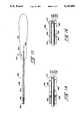
- FIG. 11is a side elevation, partially broken away, of the screw of the first alternative embodiment of the present invention.
- FIG. 12is a side elevation of the driver of the first alternative embodiment of the present invention.
- FIG. 13is a schematic side elevation view showing the screw and driver of the first alternative embodiment, the material in which the screw of the first alternative embodiment is to be implanted, and the guide wire used with the screw and driver of the first alternative embodiment;
- FIG. 14is a side elevation, taken in cross section, of the front portion of one version of the driver of the second alternative embodiment
- FIG. 15is a side elevation of the driver of the second alternative embodiment.
- FIG. 16is a side elevation, taken in cross section, of the front portion of another version of the driver of the second alternative embodiment.
- the present inventionis a screw and driver combination consisting of screw 20 and driver 50.
- Screw 20comprises an elongate shaft having a flat back end 22 and a pointed front end 24.
- Screw 20is preferably cylindrical along the majority of its length, with the front portion of the screw tapering down to pointed front end 24.
- screw 20preferably does not comprise a distinct head having a diameter which is greater than the diameter of the shaft of the screw.
- a headmay be attached to back end 22.
- Screw 20is threaded along the entire length of its outside surface.
- the specific thread pitchwill, of course, vary with application and screw size, although for a screw designed for use in arthroscopic or other closed surgeries and having a length of about one inch (1") a thread pitch of about 0.110 inches/thread is satisfactory.
- Screw 20comprises a blind axial bore 26 which is open to back end 22.
- Axial bore 26has a circular cross-section, with the diameter of the axial bore preferably being equal to roughly one-third the outside diameter of screw 20.
- the length of axial bore 26is preferably equal to about two-thirds the overall length of screw 20.
- Screw 20also comprises a blind counterbore 28 which is co-axial with axial bore 26 and is open to back end 22.
- Counterbore 28has a polygonal, preferably hexagonal, cross-section with the result that the counterbore comprises a plurality of flat elongate adjoining faces 28'.
- Counterbore 28is dimensioned so that the diameter of a circle contacting simultaneously all of the flat faces 28' of the counterbore is at least as large as the diameter of axial bore 26, and in most cases is larger than the diameter of axial bore 26.
- a seat 30is formed at the base of counterbore 28.
- the length of counterbore 28 relative to the portion of axial bore 26 having a circular cross sectionmay vary based on known design parameters, although in an exemplary screw 20 the portion of bore 26 having a circular cross section is approximately one-and-a-half times as long as counterbore 28.
- a tapered recesses 29is preferably provided at the mouth of counterbore 28.
- bore 26shall refer to the portion of bore 26 having a circular cross section, i.e. the portion of bore 26 between seat 30 and the blind end of the bore, unless specifically mentioned otherwise.
- driver 50comprises a handle 52 and an elongate shaft 54 attached to the front end of the handle.
- shaft 54must be selected so that the latter can be freely inserted into and removed from a conventional cannula.
- the length of shaft 54will, of course, vary with application.
- the front end of shaft 54tapers to a reduced diameter intermediate portion 56.
- the latterhas a polygonal cross-section, the specific polygonal shape of which corresponds to the polygonal configuration of the cross-section of counterbore 28 in the screw 20 with which the driver 50 is adapted for use.
- intermediate portion 56also has a hexagonal cross-section.
- intermediate portion 56is dimensioned to be freely slidably insertable into and removable from counterbore 28.
- intermediate portion 56is dimensioned so that when it is inserted in counterbore 28 it positively engages the sidewall of the counterbore so that rotational drive can be transmitted from intermediate portion 56 to screw 20 with minimal lost motion.
- intermediate portion 56has a reduced outside diameter relative to shaft 54.
- Intermediate portion 56joins shaft 54 with a smoothly tapering radius portion 58.
- the polygonal cross-section of intermediate portion 56is carried through tapering radius portion 58 and terminates at the junction of the radius portion with shaft 54.
- the length of intermediate portion 56, as measured between the front end 60 of the intermediate portion and front end of radius portion 58,is roughly equal to the length of counterbore 28.
- Driver 50further comprises an elongate, radially-compressible front portion 66 having a central portion 68 and a radially-projecting tip portion 70.
- Central portion 68is cylindrical in exterior configuration when not in the compressed state, and is attached at its rear end 72 to front end 60 of intermediate portion 56 so that the axes of elongation of front portion 66 and intermediate portion 56 are co-axial.
- the diameter of the central portion 68is less than the diameter of a circle circumscribing intermediate portion 56, with the result that a shoulder 69 (FIG. 4) is formed at the junction of the central portion and the intermediate portion.
- front portion 66is slightly, e.g. 0.05", shorter than bore 26.
- Tip portion 70is co-axial and integral with central portion 68, and is positioned adjacent front end 74 of front portion 66.
- Tip portion 70has a generally cylindrical exterior configuration, with the outside diameter of the tip portion being slightly greater than (i.e. 0.0005-0.0015 inches) the diameter of axial bore 26 in screw 20 when the tip portion is not in the compressed state.
- Tip portion 70tapers radially inwardly (a) at its front end to intersect front end 74 and (b) at its rear end to intersect central portion 68.
- Front portion 66further comprises an axial bore 80 which extends along the entire length of the front portion.
- the inside diameter of axial bore 80is roughly half the outside diameter of central portion 68.
- Front portion 66also includes three slots 82 extending along the length of the front portion and coupling axial bore 80 with the outside surface of the front portion. Each slot 82 is angularly spaced about the circumference of front end 74 so as to be spaced 120° from the two adjacent slots, whereby front portion 66 is divided into three equally-sized elongate segments 84a, 84b and 84c.
- each slot 82is about equal to the length of axial bore 80, while the length of the radially-innermost portion of each slot 82 is about equal to two-thirds the length of axial bore 80.
- the wall of front portion 66 in which slots 82 are providedtapers along a gradual radius between the radially-innermost and radially-outermost portions of the slots, as illustrated at 85 in FIG. 6.
- the radially-innermost and radially-outermost portions of each slot 82may be the same length or may be related in length by a relationship of other than two-thirds to one.
- the width of slots 82is approximately equal to one quarter the diameter of axial bore 80.
- axial bore 80 and slots 82are provided to allow front portion 66 to be compressed radially inwardly.
- segments 84a, 84b and 84cwill move toward one another.
- the diameter of axial bore 80, the outside diameter of tip portion 70 when in the uncompressed state, and the width and number of slots 82are selected so that tip portion 70 will snugly engage the wall of axial bore 26 with a minor spring interference fit when inserted in bore 26.
- the front ends of segments 84a, 84b and 84care driven toward one another so that the width of the front ends of slots 82 is reduced somewhat.
- Front portion 66is made from a material which can readily accommodate, without fatigue or shear, repeated compression and release of segments 84a, 84b and 84c. This material is also sufficiently resilient and has sufficient spring memory so that when segments 84a, 84b and 84c are radially compressed, the segments attain a radially-outwardly acting spring bias. Suitable materials having these properties include stainless steel and titanium.
- each of the slots 82is spaced 90° from adjacent slots, as measured around the circumference of front end 74.
- front portion 66is divided into four equally-sized, elongate segments 84a, 84b, 84c and 84d, and each slot 82 is diametrically opposite a twin slot 82.
- the radially innermost as well as the radially outermost portions of slots 82 of the alternative embodiment of front portion 66extend substantially the entire length of front portion 66, unlike the slots of the embodiment illustrated in FIGS. 4-6 (where the radially-outermost portion of the slot is preferably longer than the radially-innermost portion of the slot, as indicated at 85 in FIG. 6).
- Front portion 66comprises a pair of transverse bores 90 and 92 extending entirely through the thickness of central portion 68.
- Bore 90 and 92extend normally to the long axis of front portion 66, intersect the axial bore 80 at the inner end thereof and are perpendicularly aligned with respect to one another.
- Bore 90is positioned so that its long axis extends through one of the pairs of diametrically opposed slots 82
- bore 92is positioned so that its long axis extends through the other of the pairs of diametrically opposed slots 82.
- the diameters of bore 90 and 92are identical and are somewhat greater than the width of slots 82. Bores 90 and 92 are provided to prevent the formation of stress fractures at the base of slots 82 which might reduce the resiliency and spring memory of elongate portions 84a, 84b, 84c, and 84d.
- the outside diameter of tip portion 70 of the four-slot version of front portion 66is about 0.0020-0.004 inches, preferably 0.003 inches, greater than the inside diameter of bore 26 of screw 20.
- the outside diameter of tip portion 70 of the four-slot version of front portion 66is slightly greater than the outside diameter of the tip portion 70 of the three-slot version of front portion 66.
- Tip portion 70 of the four-slot version of front portion 66has this slightly larger diameter because the provision of four slots 82, as opposed to three slots 82, permits the four slot version of front portion 66 to be more easily radially compressed.
- the outside diameter of tip portion 70 of the four slot version of front portion 66is slightly enlarged.
- An exemplary screw and driver combination of the present inventiondesigned for use in arthroscopic or other closed surgeries, possesses the following specific dimensions:
- angle of pointed front portion30° with respect to longitudinal axis (included angle of 60°) diameter of axial bore 26: "0.0945",
- intermediate portion 56hexagonal, with diametric distance between any two parallel opposing faces equal to: 0.0928,
- central portion 680.140
- the screw and driver combination of the present inventionmay be satisfactorily used, for example, in a surgical context to secure a bone plug 100 (FIG. 10) in a hole 102 drilled in a bone 104.
- the diameter of hole 102is selected so that the corners of bone plug 100 will contact the wall of hole 102.
- a tendon (not shown) or other tissueis attached to bone plug 100 before it is inserted in hole 102.
- tip portion 70is provided with an inwardly tapering front end which coacts in cam-like fashion with either (a) tapering recess 29 at the mouth of counterbore 28 when bore 26 and counterbore 28 have similar inside diameters of (b) the mouth of bore 26 (adjacent seat 30) when the inside diameter of bore 26 is greater than the inside diameter of bore 26.
- intermediate portion 56are slightly less than the cross-sectional dimensions of screw counterbore 28 so the intermediate portion can be inserted into the counterbore with an easy sliding fit.
- the dimensions of intermediate portion 56 relative to the dimensions of counterbore 28are also selected so that rotational drive can be transmitted from driver 50 to screw 20 with minimal loss of energy.
- the pointed front end of screw 20is then inserted into one of the gaps 106 (FIG. 10) between bone plug 100 and the wall of hole 102. Because screw 20 is coupled with driver 50 as a result of the minor spring interference fit between tip 70 and axial bore 26, the screw may be directed to the opening of the gap 106 solely by appropriate manipulation of driver 50. Where screw 20 is being used in a closed surgery, the screw and driver shaft 54 may be inserted as a unit into an appropriately-positioned cannula, with the driver being manipulated based on information provided by the fiber optic or other viewing system used in conjunction with the closed surgery until the pointed front end of the screw is received in the opening of the gap 106.
- driver handle 52is rotated, causing shaft 54 and intermediate portion 56 to rotate.
- the latterhas the same polygonal configuration as and is approximately the same size as counterbore 28 so that when intermediate portion 56 is rotated it transmits rotational drive to the wall of the counterbore and hence to screw 20.
- screw 20As screw 20 is rotated, its outer threaded surface engages bone plug 100 and the adjacent portion of bone 104 and thereby pulls the screw into the bone and bone plug.
- screw 20When screw 20 is fully implanted it acts as a wedge forcing bone plug 100 into tight frictional engagement with the wall of hole 102.
- driver 50is separated from the screw by pulling the driver axially away from the screw.
- Tip portion 70resists this axial pulling to some extend so as to ensure the screw and driver do not inadvertently become separated prior to completion of the implantation of the screw.
- the minor spring interference between tip portion 70 and axial bore 26is overcome and the driver can be detached from the screw.
- K wire or other guide wire systemsare used to deliver a surgical fastener to an implantation site.
- these systemscomprise a long wire, typically having a pointed end, which is inserted into selected tissue in the surgical site.
- Surgical tools, fasteners and other devices adapted for use with guide wire systemsare delivered to the site in the tissue where the wire has been inserted by placing the device on the wire so the latter extends through the axial bore of the device. The device is then moved down the wire until it reaches the tissue.
- screw 120 and driver 150 of the alternative embodiment of the present inventionare virtually identical to screw 20 and driver 50 of the first embodiment of the present invention, except that axial bores are provided extending through the entire length of both the screw 120 and driver 150. By providing these axial bores, screw 120 and driver 150 are adapted for use with a guide wire system of the type described above.
- Describing screw 120in greater detail, the latter has a cylindrical configuration, with the pointed front end of the screw terminating in a blunt tip 123.
- the exterior surfaceis threaded, as described above with reference to screw 20.
- Screw 120comprises an axial bore 125 which extends through the entire length of the screw.
- the pointed front end of screw 120is blunted as a result of the passage of bore 125 therethrough, with the area of blunt tip 123 being equal to the area of the cross-section of bore 125.
- Screw 120includes a counterbore 126 which is co-axial with axial bore 125 and is open to rear end 122 of the screw. Screw 120 further includes a counterbore 128 which is also co-axial with axial bore 125 and is open to rear end 122 of the screw. A tapered recess 129 is provided in rear end 122 at the mouth of counterbore 128.
- the length, diameter and cross-sectional configuration of counterbores 126 and 128are equal to the length and diameter of bore 26 and counterbore 28, respectively, of screw 20.
- the diameter of axial bore 125is somewhat greater than the diameter of the guide wire with which screw 120 and driver 150 are to be used, so that the screw can slide freely along the wire.
- axial bore 125should have a diameter of about 0.045".
- the diameter of axial bore 125is always less than or equal to the diameter of counterbore 126.
- screw 120is identical to screw 20.
- driver 150comprises a handle 152, an elongate shaft 154 attached to the handle, an intermediate portion 156 attached to the front end of the elongate shaft, and a front portion 166 attached to the front end of the intermediate portion.
- An axial bore 180extends through the entire length of front portion 166.
- Elements 152-156, 166 and 180are identical in length, diameter and cross-sectional configuration to corresponding elements 52-56, 66 and 80 of driver 50.
- Driver 150differs from driver 50 only in that the former comprises a central axial bore 185 extending through the entire length of driver 150.
- central bore 185extends through handle 152, shaft 154, intermediate portion 156 and front portion 166.
- axial bore 180can be regarded as a counterbore with respect to axial bore 185, in most cases central bore 185 and axial bore 180 will be coextensive inasmuch as the diameter of central bore 185 is preferably identical to the diameter of axial bore 180.
- the diameters of axial bore 180 and central bore 185are, of course, somewhat greater than the diameter of the guide wire with which screw 120 and driver 150 are to be used.
- driver 150is identical to driver 180.
- screw 120 and driver 150are used in substantially the same manner as screw 20 and driver 50 of the first embodiment, the only difference being screw 120 and driver 150 are delivered to the implantation site using a guide wire system.
- a long thin guide wire 200is inserted into the material 300, e.g., tissue such as bone, ligament, or tendon, into which screw 120 is to be implanted.
- guide wire 200is inserted into the bone at the bottom of gap 106.
- guide wire 200is inserted into pilot hole 400 so that it penetrates into the material at the base of the pilot hole and is substantially coaxial with respect to the pilot hole.
- Guide wire 200has a diameter of approximately 0.035 inches and its leading tip 202 preferably penetrates tissue 300 to a depth of at least 0.75 inches. It is to be appreciated that the guide wire's leading tip 202 is substantially pointed so that it can more easily penetrate through into material 300. Guide wire 200 may be implanted simply by pushing it into the tissue, or it may be mounted in a drilling device (not shown) to facilitate entry.
- a supporting cannula of the sort well known in the artmay be concentrically mounted around at least a portion of the guide wire during insertion so as to help maintain the linear shape of the guide wire during penetration. If such a supporting cannula is used, it is removed from around the guide wire as soon as the guide wire has been properly positioned as shown in FIG. 13.
- the guide wire's leading tip 202may also include a helical drilling thread (not shown) to facilitate penetration. If a drilling device is used to deploy guide wire 200, the drilling device is detached from the guide wire as soon as the guide wire has been properly positioned in the manner shown in FIG. 13.
- driver 150is urged toward screw 120 so that driver front portion 166 enters counterbore 128 of screw 120.
- Driver 150is urged toward screw 120 until the driver's intermediate portion 156 reaches the mouth of counterbore 128.
- driver 150is rotated so that the flat faces of intermediate portion 156 line up with the corresponding respective flat faces of counterbore 128 of screw 120.
- driver 150is urged toward screw 120 causing intermediate portion 156 of driver 150 to enter screw counterbore 128 and driver front portion 166 to enter screw counterbore 126.
- front portion 166is radially compressed slightly so that the front portion 166 engages the wall of the counterbore 126 with a minor spring interference fit.
- driver 150When front portion 166 of driver 150 is inserted in screw 120 in this manner, by rotating driver 150, typically via handle 152, rotational drive is transmitted from driver 150 to the screw as a result of the positive rotational engagement between intermediate portion 156 of driver 150 and the wall of counterbore 128 of screw 120. Additionally, screw 120 and driver 150 are releasably coupled in an axial sense as a result of the minor spring interference between driver front portion 166 and the wall of counterbore 126 of screw 120.
- screw 120 and driver 150are loaded concentrically onto guide wire 200, with the screw's front tip 123 leading, so that the guide wire passes through the screw's axial bore 125 and the driver's central bore 185.
- Screw 120is then delivered to pilot hole 400 by moving the coupled screw and driver combination down guide wire 200 until tip 123 of screw 120 contacts the portions of material 300 surrounding the opening of the pilot hole, as illustrated in FIG. 13.
- Driver 150is then rotated, which in turn causes screw 120 to rotate, whereby the screw thread on the exterior of screw 120 engages material 300 and pulls the screw into the material.
- Driver 150is rotated until the screw is either partially or fully implanted in material 300, as desired.
- Driver 150is then separated from screw 120 by pulling the driver away from the screw with a force sufficient to overcome the minor spring interference between driver front portion 166 and screw counterbore 126. After removing driver 150 from guide wire 200, the latter is withdrawn from pilot hole 400 leaving screw 120 firmly implanted in material 300. This completes the screw implantation procedure using the screw and driver combination of the alternative embodiment.
- driver 250comprises a handle 252, an elongate shaft 254, an intermediate portion 256, and a front portion 266.
- the lattercomprises a central portion 268, a tip portion 270, and terminates at front end 274.
- Three or four slots 282are provided extending along the length of front portion 266 and coupling the exterior surface of front portion 266 with axial bore 280 which runs the entire length of front portion 266.
- Elements 252, 254, 256, 266, 268, 270, 274, 280, and 282are identical in size, configuration and number, as the case may be, respectively, to elements 52, 54, 56, 66, 68, 70, 74, 80, and 82 of driver 50 illustrated in FIGS. 3-9 and described above.
- axial bore 280is extended rearwardly through intermediate portion 266, shaft 254 and into at least the front portion of handle 252.
- an elongate shaft 293is disposed in axial bore 280.
- the outside diameter of shaft 293is selected so that the latter slides freely inside axial bore 280.
- Shaft 293terminates in a blunt end 294.
- the front end of axial bore 280tapers radially inwardly adjacent front end 274 as indicated at 295.
- a transverse slot 296is provided in handle 252 coupling axial bore 280 with the outside surface of the handle.
- a lever 297is pivotally mounted in slot 296 so as be to rotatable about an axis extending perpendicular to the long axis of shaft 254.
- One end of lever 297is flexibly attached to the rear end of shaft 293 and the other end of the lever projects out of slot 296 away from the exterior surface of handle 252.
- Lever 297is mounted and attached in this fashion so that by moving the protruding portion of lever 297 toward front portion 266, shaft 293 is caused to move rearwardly in axial bore 280 away from front end 274 of front portion 266.
- shaft 293is caused to move forwardly in axial bore 280 toward front end 274.
- Shaft 293is sized so that when the protruding portion of lever 297 is moved rearward of the vertical position, as seen in FIG. 15, blunt end 294 of shaft 293 will contact the radially-inwardly tapering portion 295 of axial bore 280. Further rearward movement of lever 297 causes blunt end 294 to move forward relative to tapering portion 295, whereby the blunt end coacts with the tapering portion in cam-like fashion causing front portion 266 to expand radially.
- Shaft 293is also sized so that when lever 297 is moved forward of the vertical position, as seen in FIG. 15, blunt end 294 of shaft 293 will not contact tapering portion 295.
- driver 250 and driver 50are differences between driver 250 and driver 50 exist for both the four slot version (FIG. 14) and the three slot version (FIG. 16) of front portion 266.
- axial bore 280may be extended to the rear end of handle 252 and a bore may be provided in shaft 293 so that driver 250 can be used with a guide wire 200 of the type described above and illustrated in FIG. 13.
- Driver 250is adapted for use with screw 20 described above, and functions in a similar manner to driver 50.
- the only difference in operation between driver 250 and driver 50is that the former, after being rotationally and axially coupled to screw 20, is actuated to cause front portion 266 to expand radially and thereby securely axially couple the front portion with the wall of bore 26 of screw 20.
- This actuationis effected by moving the protruding portion of lever 297 rearwardly so as to cause blunt end 294 of shaft 293 to move forwardly and coact in cam-like fashion with tapering portion 295. This coaction causes front portion 266 to expand radially.
- front portion 66(166, 266)is designed to engage bore 26(126) of screw 20(120) with both an interference as well as a spring fit.
- This mode of engagementis advantageous in that it provides a secure axial coupling between screw and driver and yet permits the driver to be withdrawn from the screw without the need to apply an unacceptably large axial force to the driver.
- front portion 66(166, 266) and bore 26(126)so that they engage one another with an interference fit, the limitations associated with a solely spring-biased engagement, e.g., loss of resiliency with use, are avoided.
- the first alternative embodiment of the present inventionwhich is designed for use with a guide wire system is advantageous in that it facilitates quick and easy axial alignment of the screw with the pilot hole. This ease of alignment is especially important where the screw is to be inserted in a pilot hole which is relatively inaccessible, e.g. a pilot hole located deep in a arthroscopy site.
- the second alternative embodiment of the present inventionis advantageous in that axially coupling between screw and driver is achieved by interference fit, spring bias and positive mechanical locking.
- driver 250By designing the driver 250 to include these three means for axially coupling the screw thereto, the material characteristics for driver 250 become less critical inasmuch as the spring memory characteristics of the material are less important.
Landscapes
- Health & Medical Sciences (AREA)
- Engineering & Computer Science (AREA)
- Orthopedic Medicine & Surgery (AREA)
- Surgery (AREA)
- Life Sciences & Earth Sciences (AREA)
- Animal Behavior & Ethology (AREA)
- Public Health (AREA)
- Heart & Thoracic Surgery (AREA)
- Medical Informatics (AREA)
- Molecular Biology (AREA)
- Nuclear Medicine, Radiotherapy & Molecular Imaging (AREA)
- General Health & Medical Sciences (AREA)
- Biomedical Technology (AREA)
- Veterinary Medicine (AREA)
- Signal Processing (AREA)
- Power Engineering (AREA)
- Computer Networks & Wireless Communication (AREA)
- Neurology (AREA)
- Mechanical Engineering (AREA)
- Surgical Instruments (AREA)
Abstract
Description
Claims (26)
Priority Applications (2)
| Application Number | Priority Date | Filing Date | Title |
|---|---|---|---|
| US07/579,188US5139499A (en) | 1989-02-06 | 1990-09-05 | Screw and driver |
| US07/931,167US5423819A (en) | 1989-02-06 | 1992-08-17 | Screw and driver for securing a bone block |
Applications Claiming Priority (2)
| Application Number | Priority Date | Filing Date | Title |
|---|---|---|---|
| US30734389A | 1989-02-06 | 1989-02-06 | |
| US07/579,188US5139499A (en) | 1989-02-06 | 1990-09-05 | Screw and driver |
Related Parent Applications (1)
| Application Number | Title | Priority Date | Filing Date |
|---|---|---|---|
| US30734389AContinuation | 1989-02-06 | 1989-02-06 |
Related Child Applications (1)
| Application Number | Title | Priority Date | Filing Date |
|---|---|---|---|
| US07/931,167ContinuationUS5423819A (en) | 1989-02-06 | 1992-08-17 | Screw and driver for securing a bone block |
Publications (1)
| Publication Number | Publication Date |
|---|---|
| US5139499Atrue US5139499A (en) | 1992-08-18 |
Family
ID=26975686
Family Applications (2)
| Application Number | Title | Priority Date | Filing Date |
|---|---|---|---|
| US07/579,188Expired - Fee RelatedUS5139499A (en) | 1989-02-06 | 1990-09-05 | Screw and driver |
| US07/931,167Expired - Fee RelatedUS5423819A (en) | 1989-02-06 | 1992-08-17 | Screw and driver for securing a bone block |
Family Applications After (1)
| Application Number | Title | Priority Date | Filing Date |
|---|---|---|---|
| US07/931,167Expired - Fee RelatedUS5423819A (en) | 1989-02-06 | 1992-08-17 | Screw and driver for securing a bone block |
Country Status (1)
| Country | Link |
|---|---|
| US (2) | US5139499A (en) |
Cited By (192)
| Publication number | Priority date | Publication date | Assignee | Title |
|---|---|---|---|---|
| US5354299A (en)* | 1992-12-07 | 1994-10-11 | Linvatec Corporation | Method of revising a screw in a tunnel |
| US5364400A (en)* | 1992-02-14 | 1994-11-15 | American Cyanamid Co. | Interference implant |
| US5391171A (en)* | 1992-02-19 | 1995-02-21 | Arthrex, Inc. | Pin-locked cannulated screwdriver |
| USRE34871E (en)* | 1989-05-15 | 1995-03-07 | Mcguire; David A. | Process of endosteal fixation of a ligament |
| US5407420A (en)* | 1992-11-12 | 1995-04-18 | Smith & Nephew Donjoy, Inc. | Fully adjustable shoulder brace |
| US5423819A (en)* | 1989-02-06 | 1995-06-13 | American Cyanamid Company | Screw and driver for securing a bone block |
| US5431660A (en)* | 1993-11-30 | 1995-07-11 | Burke; Dennis W. | Spring loaded screw and driver/extractor therefor |
| US5437675A (en)* | 1993-06-11 | 1995-08-01 | Wilson; Franklin D. | Polygonal bone punch |
| US5443509A (en)* | 1992-12-10 | 1995-08-22 | Linvatec Corporation | Interference bone-fixation screw with multiple interleaved threads |
| US5484440A (en)* | 1992-11-03 | 1996-01-16 | Zimmer, Inc. | Bone screw and screwdriver |
| US5562669A (en)* | 1994-01-13 | 1996-10-08 | Mcguire; David A. | Cruciate ligament reconstruction with tibial drill guide |
| US5628751A (en)* | 1993-06-21 | 1997-05-13 | United States Surgical Corporation | Orthopedic fastener applicator with rotational or longitudinal driver |
| US5649931A (en)* | 1996-01-16 | 1997-07-22 | Zimmer, Inc. | Orthopaedic apparatus for driving and/or removing a bone screw |
| US5667513A (en)* | 1995-06-07 | 1997-09-16 | Smith & Nephew Dyonics Inc. | Soft tissue anchor delivery apparatus |
| US5688276A (en)* | 1993-06-23 | 1997-11-18 | Shaffer; Benjamin | Adjustable implant holder instrument |
| US5695497A (en)* | 1994-03-29 | 1997-12-09 | Stahelin; Andreas C. | Screw made of biodegradable material for bone surgery purposes, and screwdriver suitable therefor |
| US5782832A (en)* | 1996-10-01 | 1998-07-21 | Surgical Dynamics, Inc. | Spinal fusion implant and method of insertion thereof |
| US5865834A (en)* | 1991-12-13 | 1999-02-02 | Mcguire; David A. | Coring reamer |
| US5885299A (en)* | 1994-09-15 | 1999-03-23 | Surgical Dynamics, Inc. | Apparatus and method for implant insertion |
| US5895425A (en)* | 1997-02-12 | 1999-04-20 | Arthrex, Inc. | Bone implant |
| AU708384B2 (en)* | 1994-12-12 | 1999-08-05 | Howmedica Osteonics Corp. | Conically-shaped fusion cage and method of implantation |
| US6063088A (en)* | 1997-03-24 | 2000-05-16 | United States Surgical Corporation | Method and instrumentation for implant insertion |
| US6110174A (en)* | 1992-06-12 | 2000-08-29 | Larry S. Nichter | Method of fixating bone by driving a wire through oscillation |
| US6190414B1 (en) | 1996-10-31 | 2001-02-20 | Surgical Dynamics Inc. | Apparatus for fusion of adjacent bone structures |
| US6231606B1 (en) | 1996-02-16 | 2001-05-15 | Smith & Nephew, Inc. | Graft anchor |
| ES2162765A1 (en)* | 2000-06-08 | 2002-01-01 | Socinser 21 S A | System for joining ligaments to tendons |
| WO2002000126A1 (en)* | 2000-06-23 | 2002-01-03 | University Of Southern California | Percutaneous vertebral fusion system |
| US20020151903A1 (en)* | 2001-04-12 | 2002-10-17 | Asahi Kogaku Kogyo Kabushiki Kaisha | Surgical instrument |
| US6511499B2 (en) | 1996-08-05 | 2003-01-28 | Arthrex, Inc. | Corkscrew suture anchor |
| WO2002054935A3 (en)* | 2000-12-29 | 2003-03-13 | James C Thomas Jr | Vertebral alignment system |
| US20030074002A1 (en)* | 2001-10-12 | 2003-04-17 | West Hugh S. | Interference screws having increased proximal diameter |
| US6565573B1 (en) | 2001-04-16 | 2003-05-20 | Smith & Nephew, Inc. | Orthopedic screw and method of use |
| US20030114854A1 (en)* | 1994-09-15 | 2003-06-19 | Howmedica Osteonics Corp. | Conically shaped anterior fusion cage and method of implantation |
| US6585740B2 (en) | 1998-11-26 | 2003-07-01 | Synthes (U.S.A.) | Bone screw |
| US20030125750A1 (en)* | 2001-11-05 | 2003-07-03 | Zwirnmann Ralph Fritz | Spring loaded fixation element insertion device |
| US20030125749A1 (en)* | 2001-12-27 | 2003-07-03 | Ethicon, Inc. | Cannulated screw and associated driver system |
| US20030195550A1 (en)* | 1998-08-20 | 2003-10-16 | Davison Thomas W. | Cannula for receiving surgical instruments |
| US20030236529A1 (en)* | 2002-06-24 | 2003-12-25 | Endius Incorporated | Surgical instrument for moving vertebrae |
| US20040006341A1 (en)* | 2000-06-23 | 2004-01-08 | Shaolian Samuel M. | Curable media for implantable medical device |
| US20040078051A1 (en)* | 1998-08-20 | 2004-04-22 | Davison Thomas W. | Cannula for receiving surgical instruments |
| US20040102780A1 (en)* | 2002-11-26 | 2004-05-27 | West Hugh S. | Protective devices for use with angled interference screws |
| US6743233B1 (en) | 2000-08-02 | 2004-06-01 | Orthopaedic Biosystems, Ltd., Inc. | Medical screw and method of installation |
| US6749614B2 (en) | 2000-06-23 | 2004-06-15 | Vertelink Corporation | Formable orthopedic fixation system with cross linking |
| US20040133201A1 (en)* | 2000-08-01 | 2004-07-08 | Alan Shluzas | Methods and apparatuses for treating the spine through an access device |
| US20040181232A1 (en)* | 2001-10-01 | 2004-09-16 | Paul Re | Apparatus and method for the repair of articular cartilage defects |
| US20040215193A1 (en)* | 2000-06-23 | 2004-10-28 | Shaolian Samuel M. | Formable orthopedic fixation system |
| US20040230100A1 (en)* | 2003-05-16 | 2004-11-18 | Shluzas Alan E. | Access device for minimally invasive surgery |
| US20040254575A1 (en)* | 2003-06-13 | 2004-12-16 | Obenchain Theodore G. | Method and apparatus for stabilization of facet joint |
| US20050033297A1 (en)* | 2000-08-01 | 2005-02-10 | Davison Thomas W. | Method of securing vertebrae |
| US20050075644A1 (en)* | 2003-10-02 | 2005-04-07 | Dipoto Gene | Methods and apparatuses for minimally invasive replacement of intervertebral discs |
| US20050090899A1 (en)* | 2003-10-24 | 2005-04-28 | Dipoto Gene | Methods and apparatuses for treating the spine through an access device |
| US20050090822A1 (en)* | 2003-10-24 | 2005-04-28 | Dipoto Gene | Methods and apparatus for stabilizing the spine through an access device |
| US20050090833A1 (en)* | 2003-10-24 | 2005-04-28 | Dipoto Gene | Methods and apparatuses for fixation of the spine through an access device |
| US20050149031A1 (en)* | 2003-11-26 | 2005-07-07 | Paul Ciccone | Cannulated fastener system |
| US20050188469A1 (en)* | 2004-02-27 | 2005-09-01 | Custom Spine, Inc. | Screwdriver |
| US20050228400A1 (en)* | 2004-03-31 | 2005-10-13 | Chao Nam T | Instrument for inserting, adjusting and removing pedicle screws and other orthopedic implants |
| US20050251264A1 (en)* | 2004-05-04 | 2005-11-10 | Biopro. Inc. | Subtalar implant |
| US6964667B2 (en) | 2000-06-23 | 2005-11-15 | Sdgi Holdings, Inc. | Formed in place fixation system with thermal acceleration |
| US20060041315A1 (en)* | 2004-05-04 | 2006-02-23 | Biopro, Inc. | Subtalar implant |
| US20060052812A1 (en)* | 2004-09-07 | 2006-03-09 | Michael Winer | Tool for preparing a surgical site for an access device |
| US20060106390A1 (en)* | 2004-11-18 | 2006-05-18 | Jensen David G | Composite bone fasteners |
| US20060116686A1 (en)* | 2004-11-30 | 2006-06-01 | Stryker Trauma Sa | Self-guiding threaded fastener |
| US20060129164A1 (en)* | 2004-11-03 | 2006-06-15 | Sascha Berberich | Medical instrument for manipulating objects that have a hollow channel |
| US20060149291A1 (en)* | 2004-12-15 | 2006-07-06 | Depuy Spine, Inc. | Self retaining set screw inserter |
| US7147641B2 (en) | 2001-05-30 | 2006-12-12 | Chen Michael C | Fixation element insertion device |
| US20060293750A1 (en)* | 2005-06-03 | 2006-12-28 | Sherman Michael C | Formed in place corpectomy device |
| US20070005070A1 (en)* | 2005-06-16 | 2007-01-04 | Kay David B | Self-centering screw and retaining screw driver for use in surgery |
| US20070016223A1 (en)* | 2002-10-25 | 2007-01-18 | Pagliuca James J | Apparatus and methods for shielding body structures during surgery |
| US20070027452A1 (en)* | 2005-05-18 | 2007-02-01 | Varner Signe E | Insertion instrument for non-linear medical devices |
| WO2007021850A1 (en)* | 2005-08-12 | 2007-02-22 | Smith & Nephew, Inc. | Fastener retainer and driver |
| US20070073299A1 (en)* | 1999-02-02 | 2007-03-29 | Arthrex, Inc. | Suture anchor with insert-molded eyelet shield |
| US20070078461A1 (en)* | 2005-09-27 | 2007-04-05 | Shluzas Alan E | Methods and apparatuses for stabilizing the spine through an access device |
| US20070167951A1 (en)* | 2003-10-23 | 2007-07-19 | Trans1 Inc. | Methods and tools for delivery of spinal motion preservation assemblies |
| US20070233089A1 (en)* | 2006-02-17 | 2007-10-04 | Endius, Inc. | Systems and methods for reducing adjacent level disc disease |
| US20080025788A1 (en)* | 2006-07-31 | 2008-01-31 | Dace Mark C | Helical lead for a drive shaft collet |
| US20080033448A1 (en)* | 2006-08-04 | 2008-02-07 | Robinson James C | Bone screw removal system |
| EP1929975A1 (en)* | 2006-12-07 | 2008-06-11 | Bien-Air Holding SA | Screwdriver for dental or surgical use and method for manufacturing such a screwdriver |
| US20080234717A1 (en)* | 2007-03-20 | 2008-09-25 | Medtronic Vascular, Inc. | Helical Screw Puncture Tip |
| WO2008122446A1 (en)* | 2007-04-10 | 2008-10-16 | Stryker Trauma Gmbh | Bone screw holding device |
| US20090082809A1 (en)* | 2003-04-25 | 2009-03-26 | Warsaw Orthopedic, Inc. | System and Method for Minimally Invasive Posterior Fixation |
| US7572264B2 (en) | 2005-06-28 | 2009-08-11 | Warsaw Orthopedic, Inc. | Driver instrument for use in a surgical application |
| US7601165B2 (en) | 2006-09-29 | 2009-10-13 | Biomet Sports Medicine, Llc | Method and apparatus for forming a self-locking adjustable suture loop |
| US7608092B1 (en) | 2004-02-20 | 2009-10-27 | Biomet Sports Medicince, LLC | Method and apparatus for performing meniscus repair |
| US7608098B1 (en) | 2004-11-09 | 2009-10-27 | Biomet Sports Medicine, Llc | Bone fixation device |
| US7618444B2 (en) | 2002-09-06 | 2009-11-17 | Zimmer Spine, Inc. | Surgical instrument for moving a vertebra |
| US20090287225A1 (en)* | 2008-05-15 | 2009-11-19 | Olsen Russell G | Apparatus, system, and method for orthopedic fastener insertion and extraction |
| US20100004692A1 (en)* | 2008-07-01 | 2010-01-07 | Lutz Biedermann | Bone anchor with plug member and tool for inserting the plug member into the bone anchor |
| US20100087880A1 (en)* | 2004-02-17 | 2010-04-08 | Facet Solutions, Inc. | Facet Joint Replacement Instruments and Methods |
| US7749250B2 (en) | 2006-02-03 | 2010-07-06 | Biomet Sports Medicine, Llc | Soft tissue repair assembly and associated method |
| US20100198262A1 (en)* | 2009-01-30 | 2010-08-05 | Mckinley Laurence M | Axial offset bone fastener system |
| US7771476B2 (en) | 2006-12-21 | 2010-08-10 | Warsaw Orthopedic Inc. | Curable orthopedic implant devices configured to harden after placement in vivo by application of a cure-initiating energy before insertion |
| US7799036B2 (en) | 1998-08-20 | 2010-09-21 | Zimmer Spine, Inc. | Method and apparatus for securing vertebrae |
| US20100298942A1 (en)* | 2005-04-21 | 2010-11-25 | Noah Hansell | Expandable Vertebral Prosthesis |
| US7857830B2 (en) | 2006-02-03 | 2010-12-28 | Biomet Sports Medicine, Llc | Soft tissue repair and conduit device |
| US7905903B2 (en) | 2006-02-03 | 2011-03-15 | Biomet Sports Medicine, Llc | Method for tissue fixation |
| US7905904B2 (en) | 2006-02-03 | 2011-03-15 | Biomet Sports Medicine, Llc | Soft tissue repair device and associated methods |
| US7909851B2 (en) | 2006-02-03 | 2011-03-22 | Biomet Sports Medicine, Llc | Soft tissue repair device and associated methods |
| US7914539B2 (en) | 2004-11-09 | 2011-03-29 | Biomet Sports Medicine, Llc | Tissue fixation device |
| US7959650B2 (en) | 2006-09-29 | 2011-06-14 | Biomet Sports Medicine, Llc | Adjustable knotless loops |
| US20110203422A1 (en)* | 2007-08-07 | 2011-08-25 | Ensign Michael D | Locking Screw Driver Handle |
| US8034090B2 (en) | 2004-11-09 | 2011-10-11 | Biomet Sports Medicine, Llc | Tissue fixation device |
| US8088130B2 (en) | 2006-02-03 | 2012-01-03 | Biomet Sports Medicine, Llc | Method and apparatus for coupling soft tissue to a bone |
| US8118836B2 (en) | 2004-11-05 | 2012-02-21 | Biomet Sports Medicine, Llc | Method and apparatus for coupling soft tissue to a bone |
| US8128658B2 (en) | 2004-11-05 | 2012-03-06 | Biomet Sports Medicine, Llc | Method and apparatus for coupling soft tissue to bone |
| US8137382B2 (en) | 2004-11-05 | 2012-03-20 | Biomet Sports Medicine, Llc | Method and apparatus for coupling anatomical features |
| US8162967B1 (en) | 2003-10-16 | 2012-04-24 | Biomet Sports Medicine Llc | Method and apparatus for coring and reaming of bone |
| US8251998B2 (en) | 2006-08-16 | 2012-08-28 | Biomet Sports Medicine, Llc | Chondral defect repair |
| US20120240733A1 (en)* | 2011-03-23 | 2012-09-27 | Eric Draizin | Automatically-configurable screwdriver assembly |
| US8298262B2 (en) | 2006-02-03 | 2012-10-30 | Biomet Sports Medicine, Llc | Method for tissue fixation |
| US8303604B2 (en) | 2004-11-05 | 2012-11-06 | Biomet Sports Medicine, Llc | Soft tissue repair device and method |
| US8317825B2 (en) | 2004-11-09 | 2012-11-27 | Biomet Sports Medicine, Llc | Soft tissue conduit device and method |
| US8343227B2 (en) | 2009-05-28 | 2013-01-01 | Biomet Manufacturing Corp. | Knee prosthesis assembly with ligament link |
| US8361113B2 (en) | 2006-02-03 | 2013-01-29 | Biomet Sports Medicine, Llc | Method and apparatus for coupling soft tissue to a bone |
| US8394108B2 (en) | 2010-06-18 | 2013-03-12 | Spine Wave, Inc. | Screw driver for a multiaxial bone screw |
| US20130131685A1 (en)* | 2007-07-03 | 2013-05-23 | Pioneer Surgical Technology, Inc. | Bone Plate Systems |
| US20130150864A1 (en)* | 2011-12-12 | 2013-06-13 | Warsaw Orthopedic, Inc. | Surgical instrument and method |
| US8480718B2 (en) | 2006-12-21 | 2013-07-09 | Warsaw Orthopedic, Inc. | Curable orthopedic implant devices configured to be hardened after placement in vivo |
| US8500818B2 (en) | 2006-09-29 | 2013-08-06 | Biomet Manufacturing, Llc | Knee prosthesis assembly with ligament link |
| US8506597B2 (en) | 2011-10-25 | 2013-08-13 | Biomet Sports Medicine, Llc | Method and apparatus for interosseous membrane reconstruction |
| US8512383B2 (en) | 2010-06-18 | 2013-08-20 | Spine Wave, Inc. | Method of percutaneously fixing a connecting rod to a spine |
| US8540756B2 (en) | 2010-05-03 | 2013-09-24 | Ortho Vation Medical Llc | Surgical fastener and associated systems and methods |
| US8562647B2 (en) | 2006-09-29 | 2013-10-22 | Biomet Sports Medicine, Llc | Method and apparatus for securing soft tissue to bone |
| US8562645B2 (en) | 2006-09-29 | 2013-10-22 | Biomet Sports Medicine, Llc | Method and apparatus for forming a self-locking adjustable loop |
| US8562683B2 (en) | 2004-09-14 | 2013-10-22 | Aeolin Llc | System and method for spinal fusion |
| US8574235B2 (en) | 2006-02-03 | 2013-11-05 | Biomet Sports Medicine, Llc | Method for trochanteric reattachment |
| US8597327B2 (en) | 2006-02-03 | 2013-12-03 | Biomet Manufacturing, Llc | Method and apparatus for sternal closure |
| US8623052B2 (en) | 2004-04-06 | 2014-01-07 | Arthrex, Inc. | Suture anchor |
| US8641718B2 (en) | 2010-10-19 | 2014-02-04 | Biomet Manufacturing, Llc | Method and apparatus for harvesting cartilage for treatment of a cartilage defect |
| US8652171B2 (en) | 2006-02-03 | 2014-02-18 | Biomet Sports Medicine, Llc | Method and apparatus for soft tissue fixation |
| US8652172B2 (en) | 2006-02-03 | 2014-02-18 | Biomet Sports Medicine, Llc | Flexible anchors for tissue fixation |
| US8663328B2 (en) | 2006-12-21 | 2014-03-04 | Warsaw Orthopedic, Inc. | Methods for positioning a load-bearing component of an orthopedic implant device by inserting a malleable device that hardens in vivo |
| US8672969B2 (en) | 2006-09-29 | 2014-03-18 | Biomet Sports Medicine, Llc | Fracture fixation device |
| US8721723B2 (en) | 2009-01-12 | 2014-05-13 | Globus Medical, Inc. | Expandable vertebral prosthesis |
| US8758407B2 (en) | 2006-12-21 | 2014-06-24 | Warsaw Orthopedic, Inc. | Methods for positioning a load-bearing orthopedic implant device in vivo |
| US8771352B2 (en) | 2011-05-17 | 2014-07-08 | Biomet Sports Medicine, Llc | Method and apparatus for tibial fixation of an ACL graft |
| JP2014517718A (en)* | 2011-03-28 | 2014-07-24 | シンセス・ゲーエムベーハー | Interconnected drive |
| US8801783B2 (en) | 2006-09-29 | 2014-08-12 | Biomet Sports Medicine, Llc | Prosthetic ligament system for knee joint |
| US8840645B2 (en) | 2004-11-05 | 2014-09-23 | Biomet Sports Medicine, Llc | Method and apparatus for coupling soft tissue to a bone |
| US8936621B2 (en) | 2006-02-03 | 2015-01-20 | Biomet Sports Medicine, Llc | Method and apparatus for forming a self-locking adjustable loop |
| US8968364B2 (en) | 2006-02-03 | 2015-03-03 | Biomet Sports Medicine, Llc | Method and apparatus for fixation of an ACL graft |
| US8998949B2 (en) | 2004-11-09 | 2015-04-07 | Biomet Sports Medicine, Llc | Soft tissue conduit device |
| US9017381B2 (en) | 2007-04-10 | 2015-04-28 | Biomet Sports Medicine, Llc | Adjustable knotless loops |
| US20150148853A1 (en)* | 2013-11-26 | 2015-05-28 | Nexus Spine, L.L.C. | Surgical constructs and related methods of installation |
| US9078644B2 (en) | 2006-09-29 | 2015-07-14 | Biomet Sports Medicine, Llc | Fracture fixation device |
| US9084595B2 (en) | 2011-10-19 | 2015-07-21 | Smith & Nephew Inc. | Blended shaft drive |
| US9138219B2 (en) | 2010-12-29 | 2015-09-22 | Tarsus Medical Inc. | Methods and devices for treating a syndesmosis injury |
| US9149267B2 (en) | 2006-02-03 | 2015-10-06 | Biomet Sports Medicine, Llc | Method and apparatus for coupling soft tissue to a bone |
| US20150297208A1 (en)* | 2014-04-22 | 2015-10-22 | University Hospitals Case Medical Center | Spine retractor |
| US9259217B2 (en) | 2012-01-03 | 2016-02-16 | Biomet Manufacturing, Llc | Suture Button |
| US9271713B2 (en) | 2006-02-03 | 2016-03-01 | Biomet Sports Medicine, Llc | Method and apparatus for tensioning a suture |
| US9295500B2 (en) | 2013-06-12 | 2016-03-29 | Spine Wave, Inc. | Screw driver with release for a multiaxial bone screw |
| US9314241B2 (en) | 2011-11-10 | 2016-04-19 | Biomet Sports Medicine, Llc | Apparatus for coupling soft tissue to a bone |
| US20160143671A1 (en)* | 2014-11-26 | 2016-05-26 | Ex Technology, Llc | Method and apparatus for joint fusion |
| US9357991B2 (en) | 2011-11-03 | 2016-06-07 | Biomet Sports Medicine, Llc | Method and apparatus for stitching tendons |
| US9370350B2 (en) | 2011-11-10 | 2016-06-21 | Biomet Sports Medicine, Llc | Apparatus for coupling soft tissue to a bone |
| US9381013B2 (en) | 2011-11-10 | 2016-07-05 | Biomet Sports Medicine, Llc | Method for coupling soft tissue to a bone |
| US9480518B2 (en) | 2009-07-01 | 2016-11-01 | Biedermann Technologies Gmbh & Co. Kg | Instruments for use with a bone anchor with plug member |
| US20160331481A1 (en)* | 2002-03-20 | 2016-11-17 | P Tech, Llc | Methods of using a robotic spine system |
| US9521999B2 (en) | 2005-09-13 | 2016-12-20 | Arthrex, Inc. | Fully-threaded bioabsorbable suture anchor |
| US9538998B2 (en) | 2006-02-03 | 2017-01-10 | Biomet Sports Medicine, Llc | Method and apparatus for fracture fixation |
| DE202017101447U1 (en) | 2017-03-13 | 2017-03-23 | bredent medical GmbH & Co.KG | Dental screwdriver |
| US9615822B2 (en) | 2014-05-30 | 2017-04-11 | Biomet Sports Medicine, Llc | Insertion tools and method for soft anchor |
| US20170135735A1 (en)* | 2007-12-07 | 2017-05-18 | Nexus Spine, LLC | Instruments, tools, and methods for presson pedicle screws |
| US20170156726A1 (en)* | 2012-01-24 | 2017-06-08 | DePuy Synthes Products, Inc. | Compression screw system |
| US9700291B2 (en) | 2014-06-03 | 2017-07-11 | Biomet Sports Medicine, Llc | Capsule retractor |
| US9706986B2 (en) | 2000-06-22 | 2017-07-18 | Arthrex, Inc. | Knotless suture and tissue securing method |
| US9757119B2 (en) | 2013-03-08 | 2017-09-12 | Biomet Sports Medicine, Llc | Visual aid for identifying suture limbs arthroscopically |
| US9801708B2 (en) | 2004-11-05 | 2017-10-31 | Biomet Sports Medicine, Llc | Method and apparatus for coupling soft tissue to a bone |
| US9918826B2 (en) | 2006-09-29 | 2018-03-20 | Biomet Sports Medicine, Llc | Scaffold for spring ligament repair |
| US9918827B2 (en) | 2013-03-14 | 2018-03-20 | Biomet Sports Medicine, Llc | Scaffold for spring ligament repair |
| US9936940B2 (en) | 2013-06-07 | 2018-04-10 | Biomet Sports Medicine, Llc | Method and apparatus for coupling soft tissue to bone |
| US9955980B2 (en) | 2015-02-24 | 2018-05-01 | Biomet Sports Medicine, Llc | Anatomic soft tissue repair |
| US10039543B2 (en) | 2014-08-22 | 2018-08-07 | Biomet Sports Medicine, Llc | Non-sliding soft anchor |
| US20180235684A1 (en)* | 2016-10-26 | 2018-08-23 | Nexus Spine, LLC | Self-Retaining Screwdriver |
| US10136886B2 (en) | 2013-12-20 | 2018-11-27 | Biomet Sports Medicine, Llc | Knotless soft tissue devices and techniques |
| US10226291B2 (en) | 2007-07-03 | 2019-03-12 | Pioneer Surgical Technology, Inc. | Bone plate system |
| US10413331B2 (en) | 2016-12-21 | 2019-09-17 | Spine Wave, Inc. | Spinal stabilization system with head to head cross connector |
| US10517587B2 (en) | 2006-02-03 | 2019-12-31 | Biomet Sports Medicine, Llc | Method and apparatus for forming a self-locking adjustable loop |
| USD899238S1 (en)* | 2018-05-08 | 2020-10-20 | Ryan Scott | Self tapping anchor |
| US10912551B2 (en) | 2015-03-31 | 2021-02-09 | Biomet Sports Medicine, Llc | Suture anchor with soft anchor of electrospun fibers |
| US20220054168A1 (en)* | 2020-08-19 | 2022-02-24 | Conmed Corporation | Driver for arthroscopic implant |
| US11259792B2 (en) | 2006-02-03 | 2022-03-01 | Biomet Sports Medicine, Llc | Method and apparatus for coupling anatomical features |
| US11259794B2 (en) | 2006-09-29 | 2022-03-01 | Biomet Sports Medicine, Llc | Method for implanting soft tissue |
| US11311287B2 (en) | 2006-02-03 | 2022-04-26 | Biomet Sports Medicine, Llc | Method for tissue fixation |
| US20220395357A1 (en)* | 2019-11-17 | 2022-12-15 | Solinplan Ug | Arrangement with a tool and with a fastening means, and method for fastening a fastening means |
| US11672581B2 (en) | 2020-05-29 | 2023-06-13 | DePuy Synthes Products, Inc. | Powered retaining screwdriver |
| US11877779B2 (en) | 2020-03-26 | 2024-01-23 | Xtant Medical Holdings, Inc. | Bone plate system |
| US12096928B2 (en) | 2009-05-29 | 2024-09-24 | Biomet Sports Medicine, Llc | Method and apparatus for coupling soft tissue to a bone |
| US12121268B2 (en) | 2021-07-07 | 2024-10-22 | Globus Medical, Inc. | Modular orthopedic implants, instruments, and navigation methods |
| US12245759B2 (en) | 2008-08-22 | 2025-03-11 | Biomet Sports Medicine, Llc | Method and apparatus for coupling soft tissue to bone |
| US12329373B2 (en) | 2011-05-02 | 2025-06-17 | Biomet Sports Medicine, Llc | Method and apparatus for soft tissue fixation |
| US12419632B2 (en) | 2008-08-22 | 2025-09-23 | Biomet Sports Medicine, Llc | Method and apparatus for coupling anatomical features |
Families Citing this family (61)
| Publication number | Priority date | Publication date | Assignee | Title |
|---|---|---|---|---|
| US5688285A (en)* | 1995-08-29 | 1997-11-18 | Yamada; Ikufumi | Graft bone fixation tool |
| AU713879B2 (en)* | 1995-05-08 | 1999-12-09 | Ikufumi Yamada | Graft bone fixation tool |
| US5718717A (en) | 1996-08-19 | 1998-02-17 | Bonutti; Peter M. | Suture anchor |
| US5871504A (en)* | 1997-10-21 | 1999-02-16 | Eaton; Katulle Koco | Anchor assembly and method for securing ligaments to bone |
| US6045551A (en) | 1998-02-06 | 2000-04-04 | Bonutti; Peter M. | Bone suture |
| US6146406A (en) | 1998-02-12 | 2000-11-14 | Smith & Nephew, Inc. | Bone anchor |
| US6387129B2 (en) | 1998-03-18 | 2002-05-14 | Arthrex, Inc. | Bicortical tibial fixation of ACL grafts |
| US6221107B1 (en) | 1998-08-03 | 2001-04-24 | Mark E. Steiner | Ligament fixation device and method |
| US6981974B2 (en)* | 1998-08-07 | 2006-01-03 | Berger J Lee | Cannulated internally threaded bone screw with aperatured insert |
| US6436100B1 (en) | 1998-08-07 | 2002-08-20 | J. Lee Berger | Cannulated internally threaded bone screw and reduction driver device |
| US6482210B1 (en) | 1998-11-12 | 2002-11-19 | Orthopaedic Biosystems, Ltd., Inc. | Soft tissue/ligament to bone fixation device with inserter |
| US6689153B1 (en) | 1999-04-16 | 2004-02-10 | Orthopaedic Biosystems Ltd, Inc. | Methods and apparatus for a coated anchoring device and/or suture |
| US6096060A (en)* | 1999-05-20 | 2000-08-01 | Linvatec Corporation | Bioabsorbable threaded soft tissue anchor system |
| US6368343B1 (en) | 2000-03-13 | 2002-04-09 | Peter M. Bonutti | Method of using ultrasonic vibration to secure body tissue |
| US6447516B1 (en) | 1999-08-09 | 2002-09-10 | Peter M. Bonutti | Method of securing tissue |
| US6635073B2 (en) | 2000-05-03 | 2003-10-21 | Peter M. Bonutti | Method of securing body tissue |
| US6599289B1 (en) | 2000-03-10 | 2003-07-29 | Smith & Nephew, Inc. | Graft anchor |
| US6440136B1 (en) | 2000-05-24 | 2002-08-27 | Medtronic Ps Medical, Inc. | Apparatus for attaching to bone |
| FR2812185B1 (en) | 2000-07-25 | 2003-02-28 | Spine Next Sa | SEMI-RIGID CONNECTION PIECE FOR RACHIS STABILIZATION |
| FR2812186B1 (en)* | 2000-07-25 | 2003-02-28 | Spine Next Sa | FLEXIBLE CONNECTION PIECE FOR SPINAL STABILIZATION |
| US7195642B2 (en)* | 2001-03-13 | 2007-03-27 | Mckernan Daniel J | Method and apparatus for fixing a graft in a bone tunnel |
| US6719765B2 (en) | 2001-12-03 | 2004-04-13 | Bonutti 2003 Trust-A | Magnetic suturing system and method |
| US6827722B1 (en)* | 2001-12-11 | 2004-12-07 | Biomet, Inc. | Method and apparatus for use of a guide wire capturing surgical instrument |
| US20040073219A1 (en)* | 2002-10-15 | 2004-04-15 | Skiba Jeffry B. | Insertion instrument |
| US20050049595A1 (en) | 2003-09-03 | 2005-03-03 | Suh Sean S. | Track-plate carriage system |
| US7909860B2 (en) | 2003-09-03 | 2011-03-22 | Synthes Usa, Llc | Bone plate with captive clips |
| US7678137B2 (en) | 2004-01-13 | 2010-03-16 | Life Spine, Inc. | Pedicle screw constructs for spine fixation systems |
| US7207995B1 (en) | 2004-01-29 | 2007-04-24 | Biomer Manufacturing Corp. | Method and apparatus for retaining a guide wire |
| DE202004004844U1 (en)* | 2004-03-27 | 2004-05-27 | Richard Martin Medizintechnik Gmbh | Screwdriver for bone screws |
| US7744635B2 (en)* | 2004-06-09 | 2010-06-29 | Spinal Generations, Llc | Spinal fixation system |
| US8021398B2 (en)* | 2004-06-09 | 2011-09-20 | Life Spine, Inc. | Spinal fixation system |
| US7938848B2 (en)* | 2004-06-09 | 2011-05-10 | Life Spine, Inc. | Spinal fixation system |
| WO2006058221A2 (en) | 2004-11-24 | 2006-06-01 | Abdou Samy M | Devices and methods for inter-vertebral orthopedic device placement |
| EP1971282A2 (en)* | 2006-01-10 | 2008-09-24 | Life Spine, Inc. | Pedicle screw constructs and spinal rod attachment assemblies |
| US8388660B1 (en) | 2006-08-01 | 2013-03-05 | Samy Abdou | Devices and methods for superior fixation of orthopedic devices onto the vertebral column |
| US20080177316A1 (en)* | 2006-11-30 | 2008-07-24 | Bergeron Brian J | Apparatus and methods for spinal implant |
| US20080171984A1 (en)* | 2007-01-11 | 2008-07-17 | Miller Peter C | Cannula driver and system |
| US8231635B2 (en) | 2007-01-18 | 2012-07-31 | Stryker Spine | Polyaxial screwdriver for a pedicle screw system |
| US8715348B2 (en)* | 2007-04-25 | 2014-05-06 | Alaska Hand Research LLC | Method and device for stabilizing joints with limited axial movement |
| US8679168B2 (en)* | 2008-03-03 | 2014-03-25 | Alaska Hand Research, Llc | Cannulated anchor and system |
| US20100160968A1 (en)* | 2008-12-19 | 2010-06-24 | Abbott Spine Inc. | Systems and methods for pedicle screw-based spine stabilization using flexible bands |
| CN102481187B (en)* | 2009-03-31 | 2016-06-08 | 医学嵌入公司暨Imds共同创新公司 | Double bundle acl is repaired |
| US8764806B2 (en) | 2009-12-07 | 2014-07-01 | Samy Abdou | Devices and methods for minimally invasive spinal stabilization and instrumentation |
| US8641717B2 (en) | 2010-07-01 | 2014-02-04 | DePuy Synthes Products, LLC | Guidewire insertion methods and devices |
| US9241751B2 (en)* | 2010-07-28 | 2016-01-26 | Eca Medical Instruments | Cannulated torque device and tip engagement |
| US9005249B2 (en) | 2011-07-11 | 2015-04-14 | Life Spine, Inc. | Spinal rod connector assembly |
| US8845728B1 (en) | 2011-09-23 | 2014-09-30 | Samy Abdou | Spinal fixation devices and methods of use |
| US8968402B2 (en) | 2011-10-18 | 2015-03-03 | Arthrocare Corporation | ACL implants, instruments, and methods |
| US20130226240A1 (en) | 2012-02-22 | 2013-08-29 | Samy Abdou | Spinous process fixation devices and methods of use |
| US9198767B2 (en) | 2012-08-28 | 2015-12-01 | Samy Abdou | Devices and methods for spinal stabilization and instrumentation |
| US9320617B2 (en) | 2012-10-22 | 2016-04-26 | Cogent Spine, LLC | Devices and methods for spinal stabilization and instrumentation |
| US9526553B2 (en) | 2014-04-04 | 2016-12-27 | K2M, Inc. | Screw insertion instrument |
| US10857003B1 (en) | 2015-10-14 | 2020-12-08 | Samy Abdou | Devices and methods for vertebral stabilization |
| US10973648B1 (en) | 2016-10-25 | 2021-04-13 | Samy Abdou | Devices and methods for vertebral bone realignment |
| US10744000B1 (en) | 2016-10-25 | 2020-08-18 | Samy Abdou | Devices and methods for vertebral bone realignment |
| US10973558B2 (en) | 2017-06-12 | 2021-04-13 | K2M, Inc. | Screw insertion instrument and methods of use |
| US11179248B2 (en) | 2018-10-02 | 2021-11-23 | Samy Abdou | Devices and methods for spinal implantation |
| EP3705069B1 (en) | 2019-03-05 | 2023-02-22 | K2M, Inc. | Automatic ratcheting screwdriver |
| US11020154B2 (en) | 2019-04-26 | 2021-06-01 | Warsaw Orthopedic, Inc. | Surgical instrument and methods of use |
| US11382675B2 (en) | 2020-04-01 | 2022-07-12 | EKTA-Sofia Ltd. | Surgical method for biplane screw fixation of femoral neck fractures (calcar buttressed screw fixation) |
| US12262927B2 (en) | 2020-12-10 | 2025-04-01 | K2M, Inc. | Screw insertion instrument and methods of use |
Citations (11)
| Publication number | Priority date | Publication date | Assignee | Title |
|---|---|---|---|---|
| US1410088A (en)* | 1921-03-25 | 1922-03-21 | American Telephone & Telegraph | Screw driver |
| US2593622A (en)* | 1949-02-04 | 1952-04-22 | Albert L Stanelle | Screw holding screw driver |
| US2686447A (en)* | 1953-05-11 | 1954-08-17 | Vernon L Vock | Stud extractor structure |
| US2775913A (en)* | 1955-07-20 | 1957-01-01 | Deliso John | Self-gripping tool with resilient wires for turning socket head fasteners |
| US3289290A (en)* | 1963-03-14 | 1966-12-06 | Raymond P Sandor | Method and apparatus for installing fasteners |
| US4171662A (en)* | 1976-12-20 | 1979-10-23 | Wright Line Inc. | Security screw |
| US4325153A (en)* | 1979-10-22 | 1982-04-20 | Charles Finnegan | Combined screwdriver and boring apparatus |
| SU1097307A1 (en)* | 1983-02-24 | 1984-06-15 | Центральный научно-исследовательский институт травматологии и ортопедии им.Н.Н.Приорова | Screw driver and holder for osteosynthesis |
| SU940376A1 (en)* | 1980-06-05 | 1985-02-07 | Научно-Исследовательская Лаборатория Металлоостеосинтеза С Клиникой Им.Арнольда Сеппо | Screw driver for osteosynthesis |
| SU940375A1 (en)* | 1980-06-17 | 1985-02-07 | Таллинский Политехнический Институт | Screw driver for osteosynthesis |
| US4950270A (en)* | 1989-02-03 | 1990-08-21 | Boehringer Mannheim Corporation | Cannulated self-tapping bone screw |
Family Cites Families (19)
| Publication number | Priority date | Publication date | Assignee | Title |
|---|---|---|---|---|
| US2242003A (en)* | 1940-06-13 | 1941-05-13 | Frank A Lorenzo | Method and apparatus for reduction of fracture of femur |
| US2329398A (en)* | 1941-01-23 | 1943-09-14 | Bernard A Duffy | Screw driver |
| US2570465A (en)* | 1949-08-01 | 1951-10-09 | Joseph S Lundholm | Means for fixation of hip fractures |
| GB940375A (en)* | 1959-04-02 | 1963-10-30 | Steel & Co Ltd W | Improvements in or relating to seats convertible into beds |
| GB940376A (en)* | 1959-10-14 | 1963-10-30 | Claus Holmer Gerdes | Device for electrically heating liquids |
| US3273442A (en)* | 1961-03-31 | 1966-09-20 | Launay Pierre | Screws |
| DE1291858B (en)* | 1963-12-21 | 1969-04-03 | Fritz Dr | Pistonless syringe with needle for injecting fluids, especially medicaments, and / or for puncturing |
| FR1499117A (en)* | 1965-05-17 | 1967-10-27 | Wood and machine screws, with head of any shape, or without head, with hole against the head | |
| US3405595A (en)* | 1966-10-27 | 1968-10-15 | Hardinge Brothers Inc | Devices for closing wrench sockets |
| US3888144A (en)* | 1974-02-08 | 1975-06-10 | Joseph D Parsons | Screw and driver |
| GB1565178A (en)* | 1977-02-24 | 1980-04-16 | Interfix Ltd | Bone screw |
| US4463753A (en)* | 1980-01-04 | 1984-08-07 | Gustilo Ramon B | Compression bone screw |
| US4537185A (en)* | 1983-06-10 | 1985-08-27 | Denis P. Stednitz | Cannulated fixation screw |
| US4605414A (en)* | 1984-06-06 | 1986-08-12 | John Czajka | Reconstruction of a cruciate ligament |
| FR2584151B1 (en)* | 1985-06-28 | 1988-04-29 | Saint Chamond Granat Ets | END SCREW |
| US4744793A (en)* | 1985-09-06 | 1988-05-17 | Zimmer, Inc. | Prosthetic ligament connection assembly |
| DE3811345C1 (en)* | 1988-04-02 | 1989-09-07 | Aesculap Ag, 7200 Tuttlingen, De | |
| US4950271A (en)* | 1989-02-06 | 1990-08-21 | Regents Of The University Of Minnesota | Ligament graft apparatus and method |
| US5139499A (en)* | 1989-02-06 | 1992-08-18 | American Cyanamid Company | Screw and driver |
- 1990
- 1990-09-05USUS07/579,188patent/US5139499A/ennot_activeExpired - Fee Related
- 1992
- 1992-08-17USUS07/931,167patent/US5423819A/ennot_activeExpired - Fee Related
Patent Citations (11)
| Publication number | Priority date | Publication date | Assignee | Title |
|---|---|---|---|---|
| US1410088A (en)* | 1921-03-25 | 1922-03-21 | American Telephone & Telegraph | Screw driver |
| US2593622A (en)* | 1949-02-04 | 1952-04-22 | Albert L Stanelle | Screw holding screw driver |
| US2686447A (en)* | 1953-05-11 | 1954-08-17 | Vernon L Vock | Stud extractor structure |
| US2775913A (en)* | 1955-07-20 | 1957-01-01 | Deliso John | Self-gripping tool with resilient wires for turning socket head fasteners |
| US3289290A (en)* | 1963-03-14 | 1966-12-06 | Raymond P Sandor | Method and apparatus for installing fasteners |
| US4171662A (en)* | 1976-12-20 | 1979-10-23 | Wright Line Inc. | Security screw |
| US4325153A (en)* | 1979-10-22 | 1982-04-20 | Charles Finnegan | Combined screwdriver and boring apparatus |
| SU940376A1 (en)* | 1980-06-05 | 1985-02-07 | Научно-Исследовательская Лаборатория Металлоостеосинтеза С Клиникой Им.Арнольда Сеппо | Screw driver for osteosynthesis |
| SU940375A1 (en)* | 1980-06-17 | 1985-02-07 | Таллинский Политехнический Институт | Screw driver for osteosynthesis |
| SU1097307A1 (en)* | 1983-02-24 | 1984-06-15 | Центральный научно-исследовательский институт травматологии и ортопедии им.Н.Н.Приорова | Screw driver and holder for osteosynthesis |
| US4950270A (en)* | 1989-02-03 | 1990-08-21 | Boehringer Mannheim Corporation | Cannulated self-tapping bone screw |
Non-Patent Citations (2)
| Title |
|---|
| Mueller & Co. Bone Surg. Instr. Nov. 1937.* |
| Zimmer Advertisement Jul. 1956.* |
Cited By (450)
| Publication number | Priority date | Publication date | Assignee | Title |
|---|---|---|---|---|
| US5423819A (en)* | 1989-02-06 | 1995-06-13 | American Cyanamid Company | Screw and driver for securing a bone block |
| USRE34871E (en)* | 1989-05-15 | 1995-03-07 | Mcguire; David A. | Process of endosteal fixation of a ligament |
| US5865834A (en)* | 1991-12-13 | 1999-02-02 | Mcguire; David A. | Coring reamer |
| US5364400A (en)* | 1992-02-14 | 1994-11-15 | American Cyanamid Co. | Interference implant |
| US5391171A (en)* | 1992-02-19 | 1995-02-21 | Arthrex, Inc. | Pin-locked cannulated screwdriver |
| US6110174A (en)* | 1992-06-12 | 2000-08-29 | Larry S. Nichter | Method of fixating bone by driving a wire through oscillation |
| US5484440A (en)* | 1992-11-03 | 1996-01-16 | Zimmer, Inc. | Bone screw and screwdriver |
| US5407420A (en)* | 1992-11-12 | 1995-04-18 | Smith & Nephew Donjoy, Inc. | Fully adjustable shoulder brace |
| US5354299A (en)* | 1992-12-07 | 1994-10-11 | Linvatec Corporation | Method of revising a screw in a tunnel |
| US5645547A (en)* | 1992-12-07 | 1997-07-08 | Linvatec Corporation | Revisable interference screw |
| US5443509A (en)* | 1992-12-10 | 1995-08-22 | Linvatec Corporation | Interference bone-fixation screw with multiple interleaved threads |
| US5437675A (en)* | 1993-06-11 | 1995-08-01 | Wilson; Franklin D. | Polygonal bone punch |
| US5628751A (en)* | 1993-06-21 | 1997-05-13 | United States Surgical Corporation | Orthopedic fastener applicator with rotational or longitudinal driver |
| US5643274A (en)* | 1993-06-21 | 1997-07-01 | United States Surgical Corporation | Orthopedic fastener applicator kit |
| US5688276A (en)* | 1993-06-23 | 1997-11-18 | Shaffer; Benjamin | Adjustable implant holder instrument |
| US5431660A (en)* | 1993-11-30 | 1995-07-11 | Burke; Dennis W. | Spring loaded screw and driver/extractor therefor |
| US5562669A (en)* | 1994-01-13 | 1996-10-08 | Mcguire; David A. | Cruciate ligament reconstruction with tibial drill guide |
| US5695497A (en)* | 1994-03-29 | 1997-12-09 | Stahelin; Andreas C. | Screw made of biodegradable material for bone surgery purposes, and screwdriver suitable therefor |
| US7608105B2 (en) | 1994-09-15 | 2009-10-27 | Howmedica Osteonics Corp. | Methods of inserting conically-shaped fusion cages |
| US5885299A (en)* | 1994-09-15 | 1999-03-23 | Surgical Dynamics, Inc. | Apparatus and method for implant insertion |
| US20030114854A1 (en)* | 1994-09-15 | 2003-06-19 | Howmedica Osteonics Corp. | Conically shaped anterior fusion cage and method of implantation |
| AU708384B2 (en)* | 1994-12-12 | 1999-08-05 | Howmedica Osteonics Corp. | Conically-shaped fusion cage and method of implantation |
| US5667513A (en)* | 1995-06-07 | 1997-09-16 | Smith & Nephew Dyonics Inc. | Soft tissue anchor delivery apparatus |
| US5649931A (en)* | 1996-01-16 | 1997-07-22 | Zimmer, Inc. | Orthopaedic apparatus for driving and/or removing a bone screw |
| US6231606B1 (en) | 1996-02-16 | 2001-05-15 | Smith & Nephew, Inc. | Graft anchor |
| US6336940B1 (en) | 1996-02-16 | 2002-01-08 | Smith & Nephew, Inc. | Graft anchor |
| US20030069604A1 (en)* | 1996-08-05 | 2003-04-10 | Reinhold Schmieding | Corkscrew suture anchor |
| US6916333B2 (en) | 1996-08-05 | 2005-07-12 | Arthrex, Inc. | Corkscrew suture anchor |
| US6511499B2 (en) | 1996-08-05 | 2003-01-28 | Arthrex, Inc. | Corkscrew suture anchor |
| US20060004365A1 (en)* | 1996-08-05 | 2006-01-05 | Arthrex, Inc. | Corkscrew suture anchor |
| US20070142836A1 (en)* | 1996-08-05 | 2007-06-21 | Reinhold Schmieding | Corkscrew suture anchor |
| US7195634B2 (en) | 1996-08-05 | 2007-03-27 | Arthrex, Inc. | Corkscrew suture anchor |
| US5782832A (en)* | 1996-10-01 | 1998-07-21 | Surgical Dynamics, Inc. | Spinal fusion implant and method of insertion thereof |
| US6190414B1 (en) | 1996-10-31 | 2001-02-20 | Surgical Dynamics Inc. | Apparatus for fusion of adjacent bone structures |
| US5895425A (en)* | 1997-02-12 | 1999-04-20 | Arthrex, Inc. | Bone implant |
| US6063088A (en)* | 1997-03-24 | 2000-05-16 | United States Surgical Corporation | Method and instrumentation for implant insertion |
| US20040078051A1 (en)* | 1998-08-20 | 2004-04-22 | Davison Thomas W. | Cannula for receiving surgical instruments |
| US20060276822A1 (en)* | 1998-08-20 | 2006-12-07 | Davison Thomas W | Cannula for receiving surgical instruments |
| US7892249B2 (en) | 1998-08-20 | 2011-02-22 | Zimmer Spine, Inc. | Cannula for receiving surgical instruments |
| US7799036B2 (en) | 1998-08-20 | 2010-09-21 | Zimmer Spine, Inc. | Method and apparatus for securing vertebrae |
| US7223278B2 (en) | 1998-08-20 | 2007-05-29 | Endius, Inc. | Cannula for receiving surgical instruments |
| US20030195550A1 (en)* | 1998-08-20 | 2003-10-16 | Davison Thomas W. | Cannula for receiving surgical instruments |
| US20030195551A1 (en)* | 1998-08-20 | 2003-10-16 | Davison Thomas W. | Cannula for receiving surgical instruments |
| US20030199884A1 (en)* | 1998-08-20 | 2003-10-23 | Endius Incorporated | Method for performing a surgical procedure and a cannula for use in performing the surgical procedure |
| US20030199885A1 (en)* | 1998-08-20 | 2003-10-23 | Davison Thomas W. | Cannula for receiving surgical instruments |
| US7674273B2 (en) | 1998-08-20 | 2010-03-09 | Zimmer Spine, Inc. | Method for performing a surgical procedure and a cannula for use in performing the surgical procedure |
| US8968351B2 (en) | 1998-08-20 | 2015-03-03 | Zimmer Spine, Inc. | Cannula for receiving surgical instruments |
| US7670354B2 (en) | 1998-08-20 | 2010-03-02 | Zimmer Spine, Inc. | Cannula for receiving surgical instruments |
| US20060276821A1 (en)* | 1998-08-20 | 2006-12-07 | Davison Thomas W | Cannula for receiving surgical instruments |
| US20040093002A1 (en)* | 1998-08-20 | 2004-05-13 | Davison Thomas W. | Cannula for receiving surgical instruments |
| US20040098012A1 (en)* | 1998-08-20 | 2004-05-20 | Davison Thomas W. | Cannula for receiving surgical instruments |
| US20050043754A1 (en)* | 1998-08-20 | 2005-02-24 | Davison Thomas W. | Method for performing a surgical procedure and a cannula for use in performing the surgical procedure |
| US20060264999A1 (en)* | 1998-08-20 | 2006-11-23 | Davison Thomas W | Cannula for receiving surgical instruments |
| US7108705B2 (en) | 1998-08-20 | 2006-09-19 | Endius, Inc. | Cannula for receiving surgical instruments |
| US7892171B2 (en) | 1998-08-20 | 2011-02-22 | Zimmer Spine, Inc. | Cannula for receiving surgical instruments |
| US7641670B2 (en) | 1998-08-20 | 2010-01-05 | Zimmer Spine, Inc. | Cannula for receiving surgical instruments |
| US7001397B2 (en) | 1998-08-20 | 2006-02-21 | Endius Incorporated | Cannula for receiving surgical instruments |
| US8540746B2 (en) | 1998-08-20 | 2013-09-24 | Zimmer Spine, Inc. | Cannula for receiving surgical instruments |
| US6811558B2 (en) | 1998-08-20 | 2004-11-02 | Endius Incorporated | Method for performing a surgical procedure and a cannula for use in performing the surgical procedure |
| US8317817B2 (en) | 1998-08-20 | 2012-11-27 | Zimmer Spine, Inc. | Cannula for receiving surgical instruments |
| US7985237B2 (en) | 1998-08-20 | 2011-07-26 | Zimmer Spine, Inc. | Cannula for receiving surgical instruments |
| US6585740B2 (en) | 1998-11-26 | 2003-07-01 | Synthes (U.S.A.) | Bone screw |
| US9526493B2 (en) | 1999-02-02 | 2016-12-27 | Arthrex, Inc. | Suture anchor with insert-molded rigid member |
| US9549726B2 (en) | 1999-02-02 | 2017-01-24 | Arthrex, Inc. | Suture anchor with insert-molded rigid member |
| US8821541B2 (en) | 1999-02-02 | 2014-09-02 | Arthrex, Inc. | Suture anchor with insert-molded rigid member |
| US20070073299A1 (en)* | 1999-02-02 | 2007-03-29 | Arthrex, Inc. | Suture anchor with insert-molded eyelet shield |
| ES2162765A1 (en)* | 2000-06-08 | 2002-01-01 | Socinser 21 S A | System for joining ligaments to tendons |
| US9706986B2 (en) | 2000-06-22 | 2017-07-18 | Arthrex, Inc. | Knotless suture and tissue securing method |
| US10716556B2 (en) | 2000-06-22 | 2020-07-21 | Arthtrex, Inc. | Knotless tissue fixation assembly |
| US9775599B2 (en) | 2000-06-22 | 2017-10-03 | Arthrex, Inc. | Knotless tissue fixation assembly |
| US10709436B2 (en) | 2000-06-22 | 2020-07-14 | Arthrex, Inc. | Graft fixation using a plug against suture |
| US20040006341A1 (en)* | 2000-06-23 | 2004-01-08 | Shaolian Samuel M. | Curable media for implantable medical device |
| US6964667B2 (en) | 2000-06-23 | 2005-11-15 | Sdgi Holdings, Inc. | Formed in place fixation system with thermal acceleration |
| US6899713B2 (en) | 2000-06-23 | 2005-05-31 | Vertelink Corporation | Formable orthopedic fixation system |
| US6821277B2 (en) | 2000-06-23 | 2004-11-23 | University Of Southern California Patent And Copyright Administration | Percutaneous vertebral fusion system |
| US7780705B2 (en) | 2000-06-23 | 2010-08-24 | Warsaw Orthopedic, Inc. | Formed in place fixation system with thermal acceleration |
| US7833249B2 (en) | 2000-06-23 | 2010-11-16 | Warsaw Orthopedic, Inc. | Formable orthopedic fixation system |
| US7582106B2 (en) | 2000-06-23 | 2009-09-01 | Warsaw Orthopedic, Inc. | Formable orthopedic fixation system with cross linking |
| US6875212B2 (en) | 2000-06-23 | 2005-04-05 | Vertelink Corporation | Curable media for implantable medical device |
| US20040087950A1 (en)* | 2000-06-23 | 2004-05-06 | Teitelbaum George P. | Percutaneous vertebral fusion system |
| US20050149022A1 (en)* | 2000-06-23 | 2005-07-07 | Shaolian Samuel M. | Curable media for implantable medical device |
| US20040215193A1 (en)* | 2000-06-23 | 2004-10-28 | Shaolian Samuel M. | Formable orthopedic fixation system |
| US7727262B2 (en) | 2000-06-23 | 2010-06-01 | Warsaw Orthopedic, Inc. | Formed in place fixation system with thermal acceleration |
| US8337556B2 (en) | 2000-06-23 | 2012-12-25 | Sdgi Holdings, Inc. | Curable media for implantable medical device |
| US6749614B2 (en) | 2000-06-23 | 2004-06-15 | Vertelink Corporation | Formable orthopedic fixation system with cross linking |
| US7008424B2 (en) | 2000-06-23 | 2006-03-07 | University Of Southern California | Percutaneous vertebral fusion system |
| WO2002000126A1 (en)* | 2000-06-23 | 2002-01-03 | University Of Southern California | Percutaneous vertebral fusion system |
| US8083774B2 (en) | 2000-06-23 | 2011-12-27 | Warsaw Orthopedic, Inc. | Percutaneous vertebral fusion system |
| US7056321B2 (en) | 2000-08-01 | 2006-06-06 | Endius, Incorporated | Method of securing vertebrae |
| US20050033297A1 (en)* | 2000-08-01 | 2005-02-10 | Davison Thomas W. | Method of securing vertebrae |
| US20040133201A1 (en)* | 2000-08-01 | 2004-07-08 | Alan Shluzas | Methods and apparatuses for treating the spine through an access device |
| US9101353B2 (en) | 2000-08-01 | 2015-08-11 | Zimmer Spine, Inc. | Method of securing vertebrae |
| US8277486B2 (en) | 2000-08-01 | 2012-10-02 | Zimmer Spine, Inc. | System for performing a procedure at a spinal location |
| US7850695B2 (en) | 2000-08-01 | 2010-12-14 | Zimmer Spine, Inc. | Method of securing vertebrae |
| US9622735B2 (en) | 2000-08-01 | 2017-04-18 | Zimmer Spine, Inc. | Method for securing vertebrae |
| US7722530B2 (en) | 2000-08-01 | 2010-05-25 | Zimmer Spine, Inc. | Method of securing vertebrae |
| US8777997B2 (en) | 2000-08-01 | 2014-07-15 | Zimmer Spine, Inc. | Method for securing vertebrae |
| US7699877B2 (en) | 2000-08-01 | 2010-04-20 | Zimmer Spine, Inc. | Method of securing vertebrae |
| US7985247B2 (en) | 2000-08-01 | 2011-07-26 | Zimmer Spine, Inc. | Methods and apparatuses for treating the spine through an access device |
| US8864785B2 (en) | 2000-08-01 | 2014-10-21 | Zimmer Spine, Inc. | Method for securing vertebrae |
| US6743233B1 (en) | 2000-08-02 | 2004-06-01 | Orthopaedic Biosystems, Ltd., Inc. | Medical screw and method of installation |
| WO2002054935A3 (en)* | 2000-12-29 | 2003-03-13 | James C Thomas Jr | Vertebral alignment system |
| US6964665B2 (en) | 2000-12-29 | 2005-11-15 | Thomas James C | Vertebral alignment system |
| US20020151903A1 (en)* | 2001-04-12 | 2002-10-17 | Asahi Kogaku Kogyo Kabushiki Kaisha | Surgical instrument |
| US7022124B2 (en)* | 2001-04-12 | 2006-04-04 | Pentax Corporation | Surgical instrument |
| US6565573B1 (en) | 2001-04-16 | 2003-05-20 | Smith & Nephew, Inc. | Orthopedic screw and method of use |
| US20030187447A1 (en)* | 2001-04-16 | 2003-10-02 | Joseph Ferrante | Orthopedic screw and method of use |
| US7147641B2 (en) | 2001-05-30 | 2006-12-12 | Chen Michael C | Fixation element insertion device |
| US8052691B2 (en) | 2001-05-30 | 2011-11-08 | Synthes Usa, Llc | Spring loaded fixation element insertion device |
| US20050070918A1 (en)* | 2001-05-30 | 2005-03-31 | Zwirnmann Ralph Fritz | Spring loaded fixation element insertion device |
| US8157805B2 (en)* | 2001-10-01 | 2012-04-17 | Tyco Healthcare Group Lp | Apparatus and method for the repair of articular cartilage defects |
| US20040181232A1 (en)* | 2001-10-01 | 2004-09-16 | Paul Re | Apparatus and method for the repair of articular cartilage defects |
| US20030074002A1 (en)* | 2001-10-12 | 2003-04-17 | West Hugh S. | Interference screws having increased proximal diameter |
| US6953463B2 (en) | 2001-10-12 | 2005-10-11 | Hs West Investments, Llc | Interference screws having increased proximal diameter |
| US20030125750A1 (en)* | 2001-11-05 | 2003-07-03 | Zwirnmann Ralph Fritz | Spring loaded fixation element insertion device |
| US20030125749A1 (en)* | 2001-12-27 | 2003-07-03 | Ethicon, Inc. | Cannulated screw and associated driver system |
| US10959791B2 (en) | 2002-03-20 | 2021-03-30 | P Tech, Llc | Robotic surgery |
| US10201391B2 (en)* | 2002-03-20 | 2019-02-12 | P Tech, Llc | Methods of using a robotic spine system |
| US10932869B2 (en) | 2002-03-20 | 2021-03-02 | P Tech, Llc | Robotic surgery |
| US10265128B2 (en)* | 2002-03-20 | 2019-04-23 | P Tech, Llc | Methods of using a robotic spine system |
| US10869728B2 (en) | 2002-03-20 | 2020-12-22 | P Tech, Llc | Robotic surgery |
| US10368953B2 (en) | 2002-03-20 | 2019-08-06 | P Tech, Llc | Robotic system for fastening layers of body tissue together and method thereof |
| US20160331481A1 (en)* | 2002-03-20 | 2016-11-17 | P Tech, Llc | Methods of using a robotic spine system |
| US20080221627A1 (en)* | 2002-06-24 | 2008-09-11 | Shluzas Alan E | Surgical instrument for moving vertebrae |
| US20040199170A1 (en)* | 2002-06-24 | 2004-10-07 | Endius Incorporated | Surgical instrument for moving vertebrae |
| US20030236529A1 (en)* | 2002-06-24 | 2003-12-25 | Endius Incorporated | Surgical instrument for moving vertebrae |
| US7815650B2 (en) | 2002-06-24 | 2010-10-19 | Zimmer Spine, Inc. | Surgical instrument for moving vertebrae |
| US7988700B2 (en) | 2002-06-24 | 2011-08-02 | Zimmer Spine, Inc. | Surgical instrument for moving vertebrae |
| US7341594B2 (en) | 2002-06-24 | 2008-03-11 | Endius Incorporated | Surgical instrument for moving vertebrae |
| US7713274B2 (en) | 2002-06-24 | 2010-05-11 | Zimmer Spine, Inc. | Surgical instrument for moving vertebrae |
| US20050159757A1 (en)* | 2002-06-24 | 2005-07-21 | Endius Incorporated | Surgical instrument for moving vertebrae |
| US7004947B2 (en) | 2002-06-24 | 2006-02-28 | Endius Incorporated | Surgical instrument for moving vertebrae |
| US7618444B2 (en) | 2002-09-06 | 2009-11-17 | Zimmer Spine, Inc. | Surgical instrument for moving a vertebra |
| US7988623B2 (en) | 2002-10-25 | 2011-08-02 | Zimmer Spine, Inc. | Apparatus and methods for shielding body structures during surgery |
| US20070016223A1 (en)* | 2002-10-25 | 2007-01-18 | Pagliuca James J | Apparatus and methods for shielding body structures during surgery |
| US7235078B2 (en) | 2002-11-26 | 2007-06-26 | Hs West Investments Llc | Protective devices for use with angled interference screws |
| US20040102780A1 (en)* | 2002-11-26 | 2004-05-27 | West Hugh S. | Protective devices for use with angled interference screws |
| US8317838B2 (en)* | 2003-04-25 | 2012-11-27 | Warsaw Orthopedic | System and method for minimally invasive posterior fixation |
| US20090082809A1 (en)* | 2003-04-25 | 2009-03-26 | Warsaw Orthopedic, Inc. | System and Method for Minimally Invasive Posterior Fixation |
| US7645232B2 (en) | 2003-05-16 | 2010-01-12 | Zimmer Spine, Inc. | Access device for minimally invasive surgery |
| US20040230100A1 (en)* | 2003-05-16 | 2004-11-18 | Shluzas Alan E. | Access device for minimally invasive surgery |
| US20040254575A1 (en)* | 2003-06-13 | 2004-12-16 | Obenchain Theodore G. | Method and apparatus for stabilization of facet joint |
| US7749251B2 (en)* | 2003-06-13 | 2010-07-06 | Aeolin, Llc | Method and apparatus for stabilization of facet joint |
| US20050075644A1 (en)* | 2003-10-02 | 2005-04-07 | Dipoto Gene | Methods and apparatuses for minimally invasive replacement of intervertebral discs |
| US7655012B2 (en) | 2003-10-02 | 2010-02-02 | Zimmer Spine, Inc. | Methods and apparatuses for minimally invasive replacement of intervertebral discs |
| US8162967B1 (en) | 2003-10-16 | 2012-04-24 | Biomet Sports Medicine Llc | Method and apparatus for coring and reaming of bone |
| US20070167951A1 (en)* | 2003-10-23 | 2007-07-19 | Trans1 Inc. | Methods and tools for delivery of spinal motion preservation assemblies |
| US8038680B2 (en)* | 2003-10-23 | 2011-10-18 | Trans1 Inc. | Drivers for inserts to bone anchors |
| US7938836B2 (en) | 2003-10-23 | 2011-05-10 | Trans1, Inc. | Driver assembly for simultaneous axial delivery of spinal implants |
| US20050090822A1 (en)* | 2003-10-24 | 2005-04-28 | Dipoto Gene | Methods and apparatus for stabilizing the spine through an access device |
| US7731737B2 (en) | 2003-10-24 | 2010-06-08 | Zimmer Spine, Inc. | Methods and apparatuses for fixation of the spine through an access device |
| US20050090899A1 (en)* | 2003-10-24 | 2005-04-28 | Dipoto Gene | Methods and apparatuses for treating the spine through an access device |
| US20050090833A1 (en)* | 2003-10-24 | 2005-04-28 | Dipoto Gene | Methods and apparatuses for fixation of the spine through an access device |
| US7766920B2 (en)* | 2003-11-26 | 2010-08-03 | Synthes Usa, Llc | Cannulated fastener system |
| US20050149031A1 (en)* | 2003-11-26 | 2005-07-07 | Paul Ciccone | Cannulated fastener system |
| US20100268242A1 (en)* | 2003-11-26 | 2010-10-21 | Paul Ciccone | Cannulated fastener system |
| US8282651B2 (en) | 2003-11-26 | 2012-10-09 | Synthes Usa, Llc | Cannulated fastener system |
| US9492203B2 (en)* | 2004-02-17 | 2016-11-15 | Globus Medical, Inc. | Facet joint replacement instruments and methods |
| US20120016372A1 (en)* | 2004-02-17 | 2012-01-19 | Facet Solutions, Inc. | Facet Joint Replacement Instruments and Methods |
| US9451990B2 (en)* | 2004-02-17 | 2016-09-27 | Globus Medical, Inc. | Facet joint replacement instruments and methods |
| US20100087880A1 (en)* | 2004-02-17 | 2010-04-08 | Facet Solutions, Inc. | Facet Joint Replacement Instruments and Methods |
| US7608092B1 (en) | 2004-02-20 | 2009-10-27 | Biomet Sports Medicince, LLC | Method and apparatus for performing meniscus repair |
| US8221454B2 (en) | 2004-02-20 | 2012-07-17 | Biomet Sports Medicine, Llc | Apparatus for performing meniscus repair |
| US20050188469A1 (en)* | 2004-02-27 | 2005-09-01 | Custom Spine, Inc. | Screwdriver |
| US7367979B2 (en) | 2004-02-27 | 2008-05-06 | Custom Spine, Inc. | Screwdriver |
| US20050228400A1 (en)* | 2004-03-31 | 2005-10-13 | Chao Nam T | Instrument for inserting, adjusting and removing pedicle screws and other orthopedic implants |
| US7226453B2 (en) | 2004-03-31 | 2007-06-05 | Depuy Spine, Inc. | Instrument for inserting, adjusting and removing pedicle screws and other orthopedic implants |
| US8623052B2 (en) | 2004-04-06 | 2014-01-07 | Arthrex, Inc. | Suture anchor |
| US10537319B2 (en) | 2004-04-06 | 2020-01-21 | Arthrex, Inc. | Suture anchor |
| US8801755B2 (en) | 2004-04-06 | 2014-08-12 | Arthrex, Inc. | Suture anchor |
| US9622739B2 (en) | 2004-04-06 | 2017-04-18 | Arthrex, Inc. | Suture anchor |
| US7678153B2 (en)* | 2004-05-04 | 2010-03-16 | Biopro, Inc. | Subtalar implant |
| US20050251264A1 (en)* | 2004-05-04 | 2005-11-10 | Biopro. Inc. | Subtalar implant |
| US20060041315A1 (en)* | 2004-05-04 | 2006-02-23 | Biopro, Inc. | Subtalar implant |
| US20060052812A1 (en)* | 2004-09-07 | 2006-03-09 | Michael Winer | Tool for preparing a surgical site for an access device |
| US8562683B2 (en) | 2004-09-14 | 2013-10-22 | Aeolin Llc | System and method for spinal fusion |
| US20060129164A1 (en)* | 2004-11-03 | 2006-06-15 | Sascha Berberich | Medical instrument for manipulating objects that have a hollow channel |
| US8303604B2 (en) | 2004-11-05 | 2012-11-06 | Biomet Sports Medicine, Llc | Soft tissue repair device and method |
| US10265064B2 (en) | 2004-11-05 | 2019-04-23 | Biomet Sports Medicine, Llc | Soft tissue repair device and method |
| US8551140B2 (en) | 2004-11-05 | 2013-10-08 | Biomet Sports Medicine, Llc | Method and apparatus for coupling soft tissue to bone |
| US9572655B2 (en) | 2004-11-05 | 2017-02-21 | Biomet Sports Medicine, Llc | Method and apparatus for coupling soft tissue to a bone |
| US9801708B2 (en) | 2004-11-05 | 2017-10-31 | Biomet Sports Medicine, Llc | Method and apparatus for coupling soft tissue to a bone |
| US9504460B2 (en) | 2004-11-05 | 2016-11-29 | Biomet Sports Medicine, LLC. | Soft tissue repair device and method |
| US8840645B2 (en) | 2004-11-05 | 2014-09-23 | Biomet Sports Medicine, Llc | Method and apparatus for coupling soft tissue to a bone |
| US11109857B2 (en) | 2004-11-05 | 2021-09-07 | Biomet Sports Medicine, Llc | Soft tissue repair device and method |
| US8118836B2 (en) | 2004-11-05 | 2012-02-21 | Biomet Sports Medicine, Llc | Method and apparatus for coupling soft tissue to a bone |
| US8128658B2 (en) | 2004-11-05 | 2012-03-06 | Biomet Sports Medicine, Llc | Method and apparatus for coupling soft tissue to bone |
| US8137382B2 (en) | 2004-11-05 | 2012-03-20 | Biomet Sports Medicine, Llc | Method and apparatus for coupling anatomical features |
| US7914539B2 (en) | 2004-11-09 | 2011-03-29 | Biomet Sports Medicine, Llc | Tissue fixation device |
| US7608098B1 (en) | 2004-11-09 | 2009-10-27 | Biomet Sports Medicine, Llc | Bone fixation device |
| US8034090B2 (en) | 2004-11-09 | 2011-10-11 | Biomet Sports Medicine, Llc | Tissue fixation device |
| US8317825B2 (en) | 2004-11-09 | 2012-11-27 | Biomet Sports Medicine, Llc | Soft tissue conduit device and method |
| US8998949B2 (en) | 2004-11-09 | 2015-04-07 | Biomet Sports Medicine, Llc | Soft tissue conduit device |
| US7235079B2 (en) | 2004-11-18 | 2007-06-26 | Acumed Llc | Composite bone fasteners |
| US20060106390A1 (en)* | 2004-11-18 | 2006-05-18 | Jensen David G | Composite bone fasteners |
| US20060116686A1 (en)* | 2004-11-30 | 2006-06-01 | Stryker Trauma Sa | Self-guiding threaded fastener |
| US7799062B2 (en) | 2004-11-30 | 2010-09-21 | Stryker Trauma S.A. | Self-guiding threaded fastener |
| US20060149291A1 (en)* | 2004-12-15 | 2006-07-06 | Depuy Spine, Inc. | Self retaining set screw inserter |
| US7909834B2 (en) | 2004-12-15 | 2011-03-22 | Depuy Spine, Inc. | Self retaining set screw inserter |
| US20100298942A1 (en)* | 2005-04-21 | 2010-11-25 | Noah Hansell | Expandable Vertebral Prosthesis |
| US8337559B2 (en) | 2005-04-21 | 2012-12-25 | Globus Medical, Inc. | Expandable vertebral prosthesis |
| US20070027452A1 (en)* | 2005-05-18 | 2007-02-01 | Varner Signe E | Insertion instrument for non-linear medical devices |
| US7628800B2 (en) | 2005-06-03 | 2009-12-08 | Warsaw Orthopedic, Inc. | Formed in place corpectomy device |
| US20060293750A1 (en)* | 2005-06-03 | 2006-12-28 | Sherman Michael C | Formed in place corpectomy device |
| US20070005070A1 (en)* | 2005-06-16 | 2007-01-04 | Kay David B | Self-centering screw and retaining screw driver for use in surgery |
| US7325470B2 (en)* | 2005-06-16 | 2008-02-05 | Orthohelix Surgical Designs, Inc. | Self-centering screw and retaining screw driver for use in surgery |
| US7572264B2 (en) | 2005-06-28 | 2009-08-11 | Warsaw Orthopedic, Inc. | Driver instrument for use in a surgical application |
| WO2007021850A1 (en)* | 2005-08-12 | 2007-02-22 | Smith & Nephew, Inc. | Fastener retainer and driver |
| US12064104B2 (en) | 2005-09-13 | 2024-08-20 | Arthrex, Inc. | Fully-threaded bioabsorbable suture anchor |
| US9521999B2 (en) | 2005-09-13 | 2016-12-20 | Arthrex, Inc. | Fully-threaded bioabsorbable suture anchor |
| US10595847B2 (en) | 2005-09-13 | 2020-03-24 | Arthrex, Inc. | Fully-threaded bioabsorbable suture anchor |
| US11324493B2 (en) | 2005-09-13 | 2022-05-10 | Arthrex, Inc. | Fully-threaded bioabsorbable suture anchor |
| US20070078461A1 (en)* | 2005-09-27 | 2007-04-05 | Shluzas Alan E | Methods and apparatuses for stabilizing the spine through an access device |
| US8016828B2 (en) | 2005-09-27 | 2011-09-13 | Zimmer Spine, Inc. | Methods and apparatuses for stabilizing the spine through an access device |
| US7658739B2 (en) | 2005-09-27 | 2010-02-09 | Zimmer Spine, Inc. | Methods and apparatuses for stabilizing the spine through an access device |
| US8608777B2 (en) | 2006-02-03 | 2013-12-17 | Biomet Sports Medicine | Method and apparatus for coupling soft tissue to a bone |
| US10321906B2 (en) | 2006-02-03 | 2019-06-18 | Biomet Sports Medicine, Llc | Method for tissue fixation |
| US10932770B2 (en) | 2006-02-03 | 2021-03-02 | Biomet Sports Medicine, Llc | Soft tissue repair device and associated methods |
| US10729430B2 (en) | 2006-02-03 | 2020-08-04 | Biomet Sports Medicine, Llc | Method and apparatus for coupling soft tissue to a bone |
| US12064101B2 (en) | 2006-02-03 | 2024-08-20 | Biomet Sports Medicine, Llc | Method and apparatus for forming a self-locking adjustable loop |
| US10729421B2 (en) | 2006-02-03 | 2020-08-04 | Biomet Sports Medicine, Llc | Method and apparatus for soft tissue fixation |
| US10973507B2 (en) | 2006-02-03 | 2021-04-13 | Biomet Sports Medicine, Llc | Method and apparatus for coupling soft tissue to a bone |
| US10987099B2 (en) | 2006-02-03 | 2021-04-27 | Biomet Sports Medicine, Llc | Method for tissue fixation |
| US8574235B2 (en) | 2006-02-03 | 2013-11-05 | Biomet Sports Medicine, Llc | Method for trochanteric reattachment |
| US8597327B2 (en) | 2006-02-03 | 2013-12-03 | Biomet Manufacturing, Llc | Method and apparatus for sternal closure |
| US11446019B2 (en) | 2006-02-03 | 2022-09-20 | Biomet Sports Medicine, Llc | Method and apparatus for coupling soft tissue to a bone |
| US8409253B2 (en) | 2006-02-03 | 2013-04-02 | Biomet Sports Medicine, Llc | Soft tissue repair assembly and associated method |
| US8632569B2 (en) | 2006-02-03 | 2014-01-21 | Biomet Sports Medicine, Llc | Soft tissue repair device and associated methods |
| US10716557B2 (en) | 2006-02-03 | 2020-07-21 | Biomet Sports Medicine, Llc | Method and apparatus for coupling anatomical features |
| US8652171B2 (en) | 2006-02-03 | 2014-02-18 | Biomet Sports Medicine, Llc | Method and apparatus for soft tissue fixation |
| US8652172B2 (en) | 2006-02-03 | 2014-02-18 | Biomet Sports Medicine, Llc | Flexible anchors for tissue fixation |
| US11039826B2 (en) | 2006-02-03 | 2021-06-22 | Biomet Sports Medicine, Llc | Method and apparatus for forming a self-locking adjustable loop |
| US10702259B2 (en) | 2006-02-03 | 2020-07-07 | Biomet Sports Medicine, Llc | Soft tissue repair assembly and associated method |
| US10695052B2 (en) | 2006-02-03 | 2020-06-30 | Biomet Sports Medicine, Llc | Method and apparatus for coupling soft tissue to a bone |
| US10687803B2 (en) | 2006-02-03 | 2020-06-23 | Biomet Sports Medicine, Llc | Method and apparatus for coupling soft tissue to a bone |
| US10675073B2 (en) | 2006-02-03 | 2020-06-09 | Biomet Sports Medicine, Llc | Method and apparatus for sternal closure |
| US8721684B2 (en) | 2006-02-03 | 2014-05-13 | Biomet Sports Medicine, Llc | Method and apparatus for coupling anatomical features |
| US10603029B2 (en) | 2006-02-03 | 2020-03-31 | Biomet Sports Medicine, Llc | Method and apparatus for coupling soft tissue to bone |
| US8771316B2 (en) | 2006-02-03 | 2014-07-08 | Biomet Sports Medicine, Llc | Method and apparatus for coupling anatomical features |
| US8361113B2 (en) | 2006-02-03 | 2013-01-29 | Biomet Sports Medicine, Llc | Method and apparatus for coupling soft tissue to a bone |
| US10595851B2 (en) | 2006-02-03 | 2020-03-24 | Biomet Sports Medicine, Llc | Method and apparatus for coupling soft tissue to a bone |
| US11065103B2 (en) | 2006-02-03 | 2021-07-20 | Biomet Sports Medicine, Llc | Method and apparatus for fixation of an ACL graft |
| US10542967B2 (en) | 2006-02-03 | 2020-01-28 | Biomet Sports Medicine, Llc | Method and apparatus for coupling soft tissue to a bone |
| US8337525B2 (en) | 2006-02-03 | 2012-12-25 | Biomet Sports Medicine, Llc | Soft tissue repair device and associated methods |
| US10517587B2 (en) | 2006-02-03 | 2019-12-31 | Biomet Sports Medicine, Llc | Method and apparatus for forming a self-locking adjustable loop |
| US11998185B2 (en) | 2006-02-03 | 2024-06-04 | Biomet Sports Medicine, Llc | Method and apparatus for coupling soft tissue to a bone |
| US8298262B2 (en) | 2006-02-03 | 2012-10-30 | Biomet Sports Medicine, Llc | Method for tissue fixation |
| US8292921B2 (en) | 2006-02-03 | 2012-10-23 | Biomet Sports Medicine, Llc | Soft tissue repair device and associated methods |
| US11896210B2 (en) | 2006-02-03 | 2024-02-13 | Biomet Sports Medicine, Llc | Method and apparatus for coupling soft tissue to a bone |
| US10441264B2 (en) | 2006-02-03 | 2019-10-15 | Biomet Sports Medicine, Llc | Soft tissue repair assembly and associated method |
| US8932331B2 (en) | 2006-02-03 | 2015-01-13 | Biomet Sports Medicine, Llc | Method and apparatus for coupling soft tissue to bone |
| US8936621B2 (en) | 2006-02-03 | 2015-01-20 | Biomet Sports Medicine, Llc | Method and apparatus for forming a self-locking adjustable loop |
| US8968364B2 (en) | 2006-02-03 | 2015-03-03 | Biomet Sports Medicine, Llc | Method and apparatus for fixation of an ACL graft |
| US11116495B2 (en) | 2006-02-03 | 2021-09-14 | Biomet Sports Medicine, Llc | Soft tissue repair assembly and associated method |
| US8273106B2 (en) | 2006-02-03 | 2012-09-25 | Biomet Sports Medicine, Llc | Soft tissue repair and conduit device |
| US9005287B2 (en) | 2006-02-03 | 2015-04-14 | Biomet Sports Medicine, Llc | Method for bone reattachment |
| US10398428B2 (en) | 2006-02-03 | 2019-09-03 | Biomet Sports Medicine, Llc | Method and apparatus for coupling anatomical features |
| US11259792B2 (en) | 2006-02-03 | 2022-03-01 | Biomet Sports Medicine, Llc | Method and apparatus for coupling anatomical features |
| US12096931B2 (en) | 2006-02-03 | 2024-09-24 | Biomet Sports Medicine, Llc | Method and apparatus for coupling soft tissue to a bone |
| US11284884B2 (en) | 2006-02-03 | 2022-03-29 | Biomet Sports Medicine, Llc | Method and apparatus for coupling soft tissue to a bone |
| US11819205B2 (en) | 2006-02-03 | 2023-11-21 | Biomet Sports Medicine, Llc | Soft tissue repair device and associated methods |
| US8088130B2 (en) | 2006-02-03 | 2012-01-03 | Biomet Sports Medicine, Llc | Method and apparatus for coupling soft tissue to a bone |
| US9149267B2 (en) | 2006-02-03 | 2015-10-06 | Biomet Sports Medicine, Llc | Method and apparatus for coupling soft tissue to a bone |
| US10251637B2 (en) | 2006-02-03 | 2019-04-09 | Biomet Sports Medicine, Llc | Soft tissue repair device and associated methods |
| US9173651B2 (en) | 2006-02-03 | 2015-11-03 | Biomet Sports Medicine, Llc | Soft tissue repair device and associated methods |
| US11786236B2 (en) | 2006-02-03 | 2023-10-17 | Biomet Sports Medicine, Llc | Method and apparatus for coupling anatomical features |
| US10154837B2 (en) | 2006-02-03 | 2018-12-18 | Biomet Sports Medicine, Llc | Method and apparatus for coupling soft tissue to a bone |
| US10098629B2 (en) | 2006-02-03 | 2018-10-16 | Biomet Sports Medicine, Llc | Method and apparatus for coupling soft tissue to a bone |
| US9271713B2 (en) | 2006-02-03 | 2016-03-01 | Biomet Sports Medicine, Llc | Method and apparatus for tensioning a suture |
| US10092288B2 (en) | 2006-02-03 | 2018-10-09 | Biomet Sports Medicine, Llc | Method and apparatus for coupling soft tissue to a bone |
| US10022118B2 (en) | 2006-02-03 | 2018-07-17 | Biomet Sports Medicine, Llc | Method and apparatus for coupling soft tissue to a bone |
| US10004588B2 (en) | 2006-02-03 | 2018-06-26 | Biomet Sports Medicine, Llc | Method and apparatus for fixation of an ACL graft |
| US10004489B2 (en) | 2006-02-03 | 2018-06-26 | Biomet Sports Medicine, Llc | Method and apparatus for coupling soft tissue to a bone |
| US9993241B2 (en) | 2006-02-03 | 2018-06-12 | Biomet Sports Medicine, Llc | Method and apparatus for forming a self-locking adjustable loop |
| US11311287B2 (en) | 2006-02-03 | 2022-04-26 | Biomet Sports Medicine, Llc | Method for tissue fixation |
| US9801620B2 (en) | 2006-02-03 | 2017-10-31 | Biomet Sports Medicine, Llc | Method and apparatus for coupling soft tissue to bone |
| US9402621B2 (en) | 2006-02-03 | 2016-08-02 | Biomet Sports Medicine, LLC. | Method for tissue fixation |
| US11317907B2 (en) | 2006-02-03 | 2022-05-03 | Biomet Sports Medicine, Llc | Method and apparatus for forming a self-locking adjustable loop |
| US9414833B2 (en) | 2006-02-03 | 2016-08-16 | Biomet Sports Medicine, Llc | Soft tissue repair assembly and associated method |
| US9763656B2 (en) | 2006-02-03 | 2017-09-19 | Biomet Sports Medicine, Llc | Method and apparatus for soft tissue fixation |
| US11730464B2 (en) | 2006-02-03 | 2023-08-22 | Biomet Sports Medicine, Llc | Soft tissue repair assembly and associated method |
| US11723648B2 (en) | 2006-02-03 | 2023-08-15 | Biomet Sports Medicine, Llc | Method and apparatus for soft tissue fixation |
| US9642661B2 (en) | 2006-02-03 | 2017-05-09 | Biomet Sports Medicine, Llc | Method and Apparatus for Sternal Closure |
| US9468433B2 (en) | 2006-02-03 | 2016-10-18 | Biomet Sports Medicine, Llc | Method and apparatus for forming a self-locking adjustable loop |
| US11617572B2 (en) | 2006-02-03 | 2023-04-04 | Biomet Sports Medicine, Llc | Soft tissue repair device and associated methods |
| US9622736B2 (en) | 2006-02-03 | 2017-04-18 | Biomet Sports Medicine, Llc | Soft tissue repair device and associated methods |
| US9492158B2 (en) | 2006-02-03 | 2016-11-15 | Biomet Sports Medicine, Llc | Method and apparatus for coupling soft tissue to a bone |
| US7909851B2 (en) | 2006-02-03 | 2011-03-22 | Biomet Sports Medicine, Llc | Soft tissue repair device and associated methods |
| US7905904B2 (en) | 2006-02-03 | 2011-03-15 | Biomet Sports Medicine, Llc | Soft tissue repair device and associated methods |
| US9498204B2 (en) | 2006-02-03 | 2016-11-22 | Biomet Sports Medicine, Llc | Method and apparatus for coupling anatomical features |
| US7905903B2 (en) | 2006-02-03 | 2011-03-15 | Biomet Sports Medicine, Llc | Method for tissue fixation |
| US9510821B2 (en) | 2006-02-03 | 2016-12-06 | Biomet Sports Medicine, Llc | Method and apparatus for coupling anatomical features |
| US9510819B2 (en) | 2006-02-03 | 2016-12-06 | Biomet Sports Medicine, Llc | Soft tissue repair device and associated methods |
| US11589859B2 (en) | 2006-02-03 | 2023-02-28 | Biomet Sports Medicine, Llc | Method and apparatus for coupling soft tissue to bone |
| US7857830B2 (en) | 2006-02-03 | 2010-12-28 | Biomet Sports Medicine, Llc | Soft tissue repair and conduit device |
| US9532777B2 (en) | 2006-02-03 | 2017-01-03 | Biomet Sports Medicine, Llc | Method and apparatus for coupling soft tissue to a bone |
| US9538998B2 (en) | 2006-02-03 | 2017-01-10 | Biomet Sports Medicine, Llc | Method and apparatus for fracture fixation |
| US7749250B2 (en) | 2006-02-03 | 2010-07-06 | Biomet Sports Medicine, Llc | Soft tissue repair assembly and associated method |
| US9603591B2 (en) | 2006-02-03 | 2017-03-28 | Biomet Sports Medicine, Llc | Flexible anchors for tissue fixation |
| US9561025B2 (en) | 2006-02-03 | 2017-02-07 | Biomet Sports Medicine, Llc | Soft tissue repair device and associated methods |
| US11471147B2 (en) | 2006-02-03 | 2022-10-18 | Biomet Sports Medicine, Llc | Method and apparatus for coupling soft tissue to a bone |
| US20070233089A1 (en)* | 2006-02-17 | 2007-10-04 | Endius, Inc. | Systems and methods for reducing adjacent level disc disease |
| US20100069961A1 (en)* | 2006-02-17 | 2010-03-18 | Zimmer Spine, Inc. | Systems and methods for reducing adjacent level disc disease |
| US20080025788A1 (en)* | 2006-07-31 | 2008-01-31 | Dace Mark C | Helical lead for a drive shaft collet |
| US7992878B2 (en) | 2006-07-31 | 2011-08-09 | Warsaw Orthopedic, Inc | Helical lead for a drive shaft collet |
| US20080033448A1 (en)* | 2006-08-04 | 2008-02-07 | Robinson James C | Bone screw removal system |
| US8777956B2 (en) | 2006-08-16 | 2014-07-15 | Biomet Sports Medicine, Llc | Chondral defect repair |
| US8251998B2 (en) | 2006-08-16 | 2012-08-28 | Biomet Sports Medicine, Llc | Chondral defect repair |
| US11259794B2 (en) | 2006-09-29 | 2022-03-01 | Biomet Sports Medicine, Llc | Method for implanting soft tissue |
| US8672968B2 (en) | 2006-09-29 | 2014-03-18 | Biomet Sports Medicine, Llc | Method for implanting soft tissue |
| US7658751B2 (en) | 2006-09-29 | 2010-02-09 | Biomet Sports Medicine, Llc | Method for implanting soft tissue |
| US9681940B2 (en) | 2006-09-29 | 2017-06-20 | Biomet Sports Medicine, Llc | Ligament system for knee joint |
| US7601165B2 (en) | 2006-09-29 | 2009-10-13 | Biomet Sports Medicine, Llc | Method and apparatus for forming a self-locking adjustable suture loop |
| US11376115B2 (en) | 2006-09-29 | 2022-07-05 | Biomet Sports Medicine, Llc | Prosthetic ligament system for knee joint |
| US9724090B2 (en) | 2006-09-29 | 2017-08-08 | Biomet Manufacturing, Llc | Method and apparatus for attaching soft tissue to bone |
| US7959650B2 (en) | 2006-09-29 | 2011-06-14 | Biomet Sports Medicine, Llc | Adjustable knotless loops |
| US10349931B2 (en) | 2006-09-29 | 2019-07-16 | Biomet Sports Medicine, Llc | Fracture fixation device |
| US8231654B2 (en) | 2006-09-29 | 2012-07-31 | Biomet Sports Medicine, Llc | Adjustable knotless loops |
| US9414925B2 (en) | 2006-09-29 | 2016-08-16 | Biomet Manufacturing, Llc | Method of implanting a knee prosthesis assembly with a ligament link |
| US9788876B2 (en) | 2006-09-29 | 2017-10-17 | Biomet Sports Medicine, Llc | Fracture fixation device |
| US9078644B2 (en) | 2006-09-29 | 2015-07-14 | Biomet Sports Medicine, Llc | Fracture fixation device |
| US9486211B2 (en) | 2006-09-29 | 2016-11-08 | Biomet Sports Medicine, Llc | Method for implanting soft tissue |
| US11096684B2 (en) | 2006-09-29 | 2021-08-24 | Biomet Sports Medicine, Llc | Method and apparatus for forming a self-locking adjustable loop |
| US9833230B2 (en) | 2006-09-29 | 2017-12-05 | Biomet Sports Medicine, Llc | Fracture fixation device |
| US8500818B2 (en) | 2006-09-29 | 2013-08-06 | Biomet Manufacturing, Llc | Knee prosthesis assembly with ligament link |
| US9918826B2 (en) | 2006-09-29 | 2018-03-20 | Biomet Sports Medicine, Llc | Scaffold for spring ligament repair |
| US10835232B2 (en) | 2006-09-29 | 2020-11-17 | Biomet Sports Medicine, Llc | Fracture fixation device |
| US10743925B2 (en) | 2006-09-29 | 2020-08-18 | Biomet Sports Medicine, Llc | Fracture fixation device |
| US8562647B2 (en) | 2006-09-29 | 2013-10-22 | Biomet Sports Medicine, Llc | Method and apparatus for securing soft tissue to bone |
| US8562645B2 (en) | 2006-09-29 | 2013-10-22 | Biomet Sports Medicine, Llc | Method and apparatus for forming a self-locking adjustable loop |
| US11672527B2 (en) | 2006-09-29 | 2023-06-13 | Biomet Sports Medicine, Llc | Method for implanting soft tissue |
| US10695045B2 (en) | 2006-09-29 | 2020-06-30 | Biomet Sports Medicine, Llc | Method and apparatus for attaching soft tissue to bone |
| US10004493B2 (en) | 2006-09-29 | 2018-06-26 | Biomet Sports Medicine, Llc | Method for implanting soft tissue |
| US8672969B2 (en) | 2006-09-29 | 2014-03-18 | Biomet Sports Medicine, Llc | Fracture fixation device |
| US10610217B2 (en) | 2006-09-29 | 2020-04-07 | Biomet Sports Medicine, Llc | Method and apparatus for forming a self-locking adjustable loop |
| US9539003B2 (en) | 2006-09-29 | 2017-01-10 | Biomet Sports Medicine, LLC. | Method and apparatus for forming a self-locking adjustable loop |
| US10517714B2 (en) | 2006-09-29 | 2019-12-31 | Biomet Sports Medicine, Llc | Ligament system for knee joint |
| US8801783B2 (en) | 2006-09-29 | 2014-08-12 | Biomet Sports Medicine, Llc | Prosthetic ligament system for knee joint |
| US10398430B2 (en) | 2006-09-29 | 2019-09-03 | Biomet Sports Medicine, Llc | Method for implanting soft tissue |
| EP1929975A1 (en)* | 2006-12-07 | 2008-06-11 | Bien-Air Holding SA | Screwdriver for dental or surgical use and method for manufacturing such a screwdriver |
| US8663328B2 (en) | 2006-12-21 | 2014-03-04 | Warsaw Orthopedic, Inc. | Methods for positioning a load-bearing component of an orthopedic implant device by inserting a malleable device that hardens in vivo |
| US8480718B2 (en) | 2006-12-21 | 2013-07-09 | Warsaw Orthopedic, Inc. | Curable orthopedic implant devices configured to be hardened after placement in vivo |
| US8758407B2 (en) | 2006-12-21 | 2014-06-24 | Warsaw Orthopedic, Inc. | Methods for positioning a load-bearing orthopedic implant device in vivo |
| US7771476B2 (en) | 2006-12-21 | 2010-08-10 | Warsaw Orthopedic Inc. | Curable orthopedic implant devices configured to harden after placement in vivo by application of a cure-initiating energy before insertion |
| US11612391B2 (en) | 2007-01-16 | 2023-03-28 | Biomet Sports Medicine, Llc | Soft tissue repair device and associated methods |
| US20080234717A1 (en)* | 2007-03-20 | 2008-09-25 | Medtronic Vascular, Inc. | Helical Screw Puncture Tip |
| US9861351B2 (en) | 2007-04-10 | 2018-01-09 | Biomet Sports Medicine, Llc | Adjustable knotless loops |
| US10729423B2 (en) | 2007-04-10 | 2020-08-04 | Biomet Sports Medicine, Llc | Adjustable knotless loops |
| US12303122B2 (en) | 2007-04-10 | 2025-05-20 | Biomet Sports Medicine, Llc | Adjustable knotless loops |
| US11185320B2 (en) | 2007-04-10 | 2021-11-30 | Biomet Sports Medicine, Llc | Adjustable knotless loops |
| US9017381B2 (en) | 2007-04-10 | 2015-04-28 | Biomet Sports Medicine, Llc | Adjustable knotless loops |
| US20080269768A1 (en)* | 2007-04-10 | 2008-10-30 | Stryker Trauma Sa | Bone screw holding device |
| WO2008122446A1 (en)* | 2007-04-10 | 2008-10-16 | Stryker Trauma Gmbh | Bone screw holding device |
| US9655665B2 (en)* | 2007-07-03 | 2017-05-23 | Pioneer Surgical Technology, Inc. | Bone plate systems |
| US10226291B2 (en) | 2007-07-03 | 2019-03-12 | Pioneer Surgical Technology, Inc. | Bone plate system |
| US10898247B2 (en) | 2007-07-03 | 2021-01-26 | Pioneer Surgical Technology, Inc. | Bone plate system |
| US20130131685A1 (en)* | 2007-07-03 | 2013-05-23 | Pioneer Surgical Technology, Inc. | Bone Plate Systems |
| US20110203422A1 (en)* | 2007-08-07 | 2011-08-25 | Ensign Michael D | Locking Screw Driver Handle |
| US9801667B2 (en)* | 2007-12-07 | 2017-10-31 | Nexus Spine, L.L.C. | Instruments, tools, and methods for presson pedicle screws |
| US20170135735A1 (en)* | 2007-12-07 | 2017-05-18 | Nexus Spine, LLC | Instruments, tools, and methods for presson pedicle screws |
| US8292899B2 (en) | 2008-05-15 | 2012-10-23 | Olsen Russell G | Apparatus and system for orthopedic fastener insertion and extraction |
| US20090287225A1 (en)* | 2008-05-15 | 2009-11-19 | Olsen Russell G | Apparatus, system, and method for orthopedic fastener insertion and extraction |
| US9730745B2 (en) | 2008-07-01 | 2017-08-15 | Biedermann Technologies Gmbh & Co. Kg | Bone anchor with plug member and tool for inserting the plug member into the bone anchor |
| US9265539B2 (en) | 2008-07-01 | 2016-02-23 | Biedermann Technologies Gmbh & Co. Kg | Bone anchor with plug member and tool for inserting the plug member into the bone anchor |
| US20100004692A1 (en)* | 2008-07-01 | 2010-01-07 | Lutz Biedermann | Bone anchor with plug member and tool for inserting the plug member into the bone anchor |
| US8690930B2 (en)* | 2008-07-01 | 2014-04-08 | Biedermann Technologies Gmbh & Co. Kg | Bone anchor with plug member and tool for inserting the plug member into the bone anchor |
| US12245759B2 (en) | 2008-08-22 | 2025-03-11 | Biomet Sports Medicine, Llc | Method and apparatus for coupling soft tissue to bone |
| US11534159B2 (en) | 2008-08-22 | 2022-12-27 | Biomet Sports Medicine, Llc | Method and apparatus for coupling soft tissue to a bone |
| US12419632B2 (en) | 2008-08-22 | 2025-09-23 | Biomet Sports Medicine, Llc | Method and apparatus for coupling anatomical features |
| US9962268B2 (en) | 2009-01-12 | 2018-05-08 | Globus Medical, Inc. | Expandable vertebral prosthesis |
| US8721723B2 (en) | 2009-01-12 | 2014-05-13 | Globus Medical, Inc. | Expandable vertebral prosthesis |
| US11399951B2 (en) | 2009-01-12 | 2022-08-02 | Globus Medical, Inc. | Expandable vertebral prosthesis |
| US10314717B2 (en) | 2009-01-12 | 2019-06-11 | Globus Medical, Inc. | Expandable vertebral prosthesis |
| US12220324B2 (en) | 2009-01-12 | 2025-02-11 | Globus Medical, Inc. | Expandable vertebral prosthesis |
| US20100198262A1 (en)* | 2009-01-30 | 2010-08-05 | Mckinley Laurence M | Axial offset bone fastener system |
| US8343227B2 (en) | 2009-05-28 | 2013-01-01 | Biomet Manufacturing Corp. | Knee prosthesis assembly with ligament link |
| US8900314B2 (en) | 2009-05-28 | 2014-12-02 | Biomet Manufacturing, Llc | Method of implanting a prosthetic knee joint assembly |
| US10149767B2 (en) | 2009-05-28 | 2018-12-11 | Biomet Manufacturing, Llc | Method of implanting knee prosthesis assembly with ligament link |
| US12096928B2 (en) | 2009-05-29 | 2024-09-24 | Biomet Sports Medicine, Llc | Method and apparatus for coupling soft tissue to a bone |
| US12251093B2 (en) | 2009-05-29 | 2025-03-18 | Biomet Sports Medicine, Llc | Method and apparatus for coupling soft tissue to a bone |
| US9480518B2 (en) | 2009-07-01 | 2016-11-01 | Biedermann Technologies Gmbh & Co. Kg | Instruments for use with a bone anchor with plug member |
| US8540756B2 (en) | 2010-05-03 | 2013-09-24 | Ortho Vation Medical Llc | Surgical fastener and associated systems and methods |
| US8394108B2 (en) | 2010-06-18 | 2013-03-12 | Spine Wave, Inc. | Screw driver for a multiaxial bone screw |
| US8512383B2 (en) | 2010-06-18 | 2013-08-20 | Spine Wave, Inc. | Method of percutaneously fixing a connecting rod to a spine |
| US9456900B2 (en) | 2010-10-19 | 2016-10-04 | Biomet Manufacturing, Llc | Method and apparatus for harvesting cartilage for treatment of a cartilage defect |
| US8641718B2 (en) | 2010-10-19 | 2014-02-04 | Biomet Manufacturing, Llc | Method and apparatus for harvesting cartilage for treatment of a cartilage defect |
| US9138219B2 (en) | 2010-12-29 | 2015-09-22 | Tarsus Medical Inc. | Methods and devices for treating a syndesmosis injury |
| US8770069B2 (en)* | 2011-03-23 | 2014-07-08 | Eric Draizin | Automatically-configurable screwdriver assembly |
| US20120240733A1 (en)* | 2011-03-23 | 2012-09-27 | Eric Draizin | Automatically-configurable screwdriver assembly |
| JP2014517718A (en)* | 2011-03-28 | 2014-07-24 | シンセス・ゲーエムベーハー | Interconnected drive |
| US12336701B2 (en) | 2011-05-02 | 2025-06-24 | Biomet Sports Medicine, Llc | Method and apparatus for soft tissue fixation |
| US12329373B2 (en) | 2011-05-02 | 2025-06-17 | Biomet Sports Medicine, Llc | Method and apparatus for soft tissue fixation |
| US8771352B2 (en) | 2011-05-17 | 2014-07-08 | Biomet Sports Medicine, Llc | Method and apparatus for tibial fixation of an ACL graft |
| US9216078B2 (en) | 2011-05-17 | 2015-12-22 | Biomet Sports Medicine, Llc | Method and apparatus for tibial fixation of an ACL graft |
| US9084595B2 (en) | 2011-10-19 | 2015-07-21 | Smith & Nephew Inc. | Blended shaft drive |
| US10052093B2 (en) | 2011-10-19 | 2018-08-21 | Smith & Nephew, Inc. | Blended shaft drive |
| US8506597B2 (en) | 2011-10-25 | 2013-08-13 | Biomet Sports Medicine, Llc | Method and apparatus for interosseous membrane reconstruction |
| US9445827B2 (en) | 2011-10-25 | 2016-09-20 | Biomet Sports Medicine, Llc | Method and apparatus for intraosseous membrane reconstruction |
| US10265159B2 (en) | 2011-11-03 | 2019-04-23 | Biomet Sports Medicine, Llc | Method and apparatus for stitching tendons |
| US11241305B2 (en) | 2011-11-03 | 2022-02-08 | Biomet Sports Medicine, Llc | Method and apparatus for stitching tendons |
| US9357991B2 (en) | 2011-11-03 | 2016-06-07 | Biomet Sports Medicine, Llc | Method and apparatus for stitching tendons |
| US9314241B2 (en) | 2011-11-10 | 2016-04-19 | Biomet Sports Medicine, Llc | Apparatus for coupling soft tissue to a bone |
| US10363028B2 (en) | 2011-11-10 | 2019-07-30 | Biomet Sports Medicine, Llc | Method for coupling soft tissue to a bone |
| US11534157B2 (en) | 2011-11-10 | 2022-12-27 | Biomet Sports Medicine, Llc | Method for coupling soft tissue to a bone |
| US9370350B2 (en) | 2011-11-10 | 2016-06-21 | Biomet Sports Medicine, Llc | Apparatus for coupling soft tissue to a bone |
| US9381013B2 (en) | 2011-11-10 | 2016-07-05 | Biomet Sports Medicine, Llc | Method for coupling soft tissue to a bone |
| US10368856B2 (en) | 2011-11-10 | 2019-08-06 | Biomet Sports Medicine, Llc | Apparatus for coupling soft tissue to a bone |
| US9357992B2 (en) | 2011-11-10 | 2016-06-07 | Biomet Sports Medicine, Llc | Method for coupling soft tissue to a bone |
| US20130150864A1 (en)* | 2011-12-12 | 2013-06-13 | Warsaw Orthopedic, Inc. | Surgical instrument and method |
| US9259217B2 (en) | 2012-01-03 | 2016-02-16 | Biomet Manufacturing, Llc | Suture Button |
| US9433407B2 (en) | 2012-01-03 | 2016-09-06 | Biomet Manufacturing, Llc | Method of implanting a bone fixation assembly |
| US11197667B2 (en)* | 2012-01-24 | 2021-12-14 | DePuy Synthes Products, Inc. | Compression screw system |
| US20170156726A1 (en)* | 2012-01-24 | 2017-06-08 | DePuy Synthes Products, Inc. | Compression screw system |
| US9757119B2 (en) | 2013-03-08 | 2017-09-12 | Biomet Sports Medicine, Llc | Visual aid for identifying suture limbs arthroscopically |
| US10758221B2 (en) | 2013-03-14 | 2020-09-01 | Biomet Sports Medicine, Llc | Scaffold for spring ligament repair |
| US9918827B2 (en) | 2013-03-14 | 2018-03-20 | Biomet Sports Medicine, Llc | Scaffold for spring ligament repair |
| US20180256152A1 (en)* | 2013-06-07 | 2018-09-13 | Biomet Sports Medicine, Llc | Method and apparatus for coupling soft tissue to bone |
| US10842481B2 (en)* | 2013-06-07 | 2020-11-24 | Biomet Sports Medicine, Llc | Method and apparatus for coupling soft tissue to bone |
| US9936940B2 (en) | 2013-06-07 | 2018-04-10 | Biomet Sports Medicine, Llc | Method and apparatus for coupling soft tissue to bone |
| US9295500B2 (en) | 2013-06-12 | 2016-03-29 | Spine Wave, Inc. | Screw driver with release for a multiaxial bone screw |
| US20150148853A1 (en)* | 2013-11-26 | 2015-05-28 | Nexus Spine, L.L.C. | Surgical constructs and related methods of installation |
| US11266447B2 (en)* | 2013-11-26 | 2022-03-08 | Nexus Spine, L.L.C. | Surgical constructs and related methods of installation |
| US10806443B2 (en) | 2013-12-20 | 2020-10-20 | Biomet Sports Medicine, Llc | Knotless soft tissue devices and techniques |
| US12251100B2 (en) | 2013-12-20 | 2025-03-18 | Biomet Sports Medicine, Llc | Knotless soft tissue devices and techniques |
| US11648004B2 (en) | 2013-12-20 | 2023-05-16 | Biomet Sports Medicine, Llc | Knotless soft tissue devices and techniques |
| US10136886B2 (en) | 2013-12-20 | 2018-11-27 | Biomet Sports Medicine, Llc | Knotless soft tissue devices and techniques |
| US20150297208A1 (en)* | 2014-04-22 | 2015-10-22 | University Hospitals Case Medical Center | Spine retractor |
| US10172601B2 (en)* | 2014-04-22 | 2019-01-08 | University Hospitals Cleveland Medical Center | Spine retractor |
| US9615822B2 (en) | 2014-05-30 | 2017-04-11 | Biomet Sports Medicine, Llc | Insertion tools and method for soft anchor |
| US9700291B2 (en) | 2014-06-03 | 2017-07-11 | Biomet Sports Medicine, Llc | Capsule retractor |
| US11219443B2 (en) | 2014-08-22 | 2022-01-11 | Biomet Sports Medicine, Llc | Non-sliding soft anchor |
| US10743856B2 (en) | 2014-08-22 | 2020-08-18 | Biomet Sports Medicine, Llc | Non-sliding soft anchor |
| US12193656B2 (en) | 2014-08-22 | 2025-01-14 | Biomet Sports Medicine, Llc | Non-sliding soft anchor |
| US10039543B2 (en) | 2014-08-22 | 2018-08-07 | Biomet Sports Medicine, Llc | Non-sliding soft anchor |
| US20180235670A1 (en)* | 2014-11-26 | 2018-08-23 | Ex Technology, Llc | Method and apparatus for joint fusion |
| US11000316B2 (en)* | 2014-11-26 | 2021-05-11 | Ex Technology, Llc | Method and apparatus for joint fusion |
| US20160143671A1 (en)* | 2014-11-26 | 2016-05-26 | Ex Technology, Llc | Method and apparatus for joint fusion |
| US9931141B2 (en)* | 2014-11-26 | 2018-04-03 | Ex Technology, Llc | Method and apparatus for joint fusion |
| US9955980B2 (en) | 2015-02-24 | 2018-05-01 | Biomet Sports Medicine, Llc | Anatomic soft tissue repair |
| US10912551B2 (en) | 2015-03-31 | 2021-02-09 | Biomet Sports Medicine, Llc | Suture anchor with soft anchor of electrospun fibers |
| US20180235684A1 (en)* | 2016-10-26 | 2018-08-23 | Nexus Spine, LLC | Self-Retaining Screwdriver |
| US11395684B2 (en) | 2016-12-21 | 2022-07-26 | Spine Wave, Inc. | Head to head cross connector |
| US10413331B2 (en) | 2016-12-21 | 2019-09-17 | Spine Wave, Inc. | Spinal stabilization system with head to head cross connector |
| DE202017101447U1 (en) | 2017-03-13 | 2017-03-23 | bredent medical GmbH & Co.KG | Dental screwdriver |
| USD899238S1 (en)* | 2018-05-08 | 2020-10-20 | Ryan Scott | Self tapping anchor |
| US20220395357A1 (en)* | 2019-11-17 | 2022-12-15 | Solinplan Ug | Arrangement with a tool and with a fastening means, and method for fastening a fastening means |
| US11877779B2 (en) | 2020-03-26 | 2024-01-23 | Xtant Medical Holdings, Inc. | Bone plate system |
| US11672581B2 (en) | 2020-05-29 | 2023-06-13 | DePuy Synthes Products, Inc. | Powered retaining screwdriver |
| US20220054168A1 (en)* | 2020-08-19 | 2022-02-24 | Conmed Corporation | Driver for arthroscopic implant |
| US12121268B2 (en) | 2021-07-07 | 2024-10-22 | Globus Medical, Inc. | Modular orthopedic implants, instruments, and navigation methods |
Also Published As
| Publication number | Publication date |
|---|---|
| US5423819A (en) | 1995-06-13 |
Similar Documents
| Publication | Publication Date | Title |
|---|---|---|
| US5139499A (en) | Screw and driver | |
| WO1990008510A1 (en) | Screw and driver | |
| US6250865B1 (en) | Screw tipped anchor assembly | |
| US10842481B2 (en) | Method and apparatus for coupling soft tissue to bone | |
| US9920873B1 (en) | Bursting head device | |
| US20020049447A1 (en) | Expandable surgical fastener and method | |
| EP3551894B1 (en) | Anchor assembly for fastener | |
| US20080161814A1 (en) | Device and method for mounting an object on a bone | |
| EP3160687B1 (en) | Screwdriver | |
| CA3066416C (en) | Orthopedic drill bit with swiveling head | |
| US12004792B2 (en) | Headless compression screw driver system | |
| KR20080027250A (en) | Bone Connector with Swivel Joint | |
| CA2502044A1 (en) | Anchor assembly for fastener | |
| CN113069198B (en) | Novel nail puller | |
| CN108697444A (en) | Instrument for being directed to bar in implantation material retainer | |
| US20070093791A1 (en) | Device for removal of fastening means from human tissue | |
| KR20150138424A (en) | Osteosynthesis device for proximal femur fracture and master screw type screw device for osteosynthesis device for proximal femur fracture | |
| AU749876B2 (en) | Screw tipped anchor assembly | |
| CN117693636A (en) | Wall anchor with deformable extension | |
| CN208942242U (en) | Ligament fixing screws the reconstruction tool | |
| US20140194936A1 (en) | Undercut screw feature and driver | |
| US20220192796A1 (en) | Laterally expanding dental implant | |
| CN112135569B (en) | Anchor delivery system | |
| WO2012026915A1 (en) | Driver-screw retention mechanism | |
| AU2019232840A1 (en) | Anchor assembly for fastener |
Legal Events
| Date | Code | Title | Description |
|---|---|---|---|
| FEPP | Fee payment procedure | Free format text:PAYOR NUMBER ASSIGNED (ORIGINAL EVENT CODE: ASPN); ENTITY STATUS OF PATENT OWNER: LARGE ENTITY | |
| AS | Assignment | Owner name:AMERICAN CYANAMID COMPANY, CONNECTICUT Free format text:ASSIGNMENT OF ASSIGNORS INTEREST.;ASSIGNOR:ACUFEX MICROSURGICAL INC.;REEL/FRAME:006115/0837 Effective date:19920507 | |
| FPAY | Fee payment | Year of fee payment:4 | |
| AS | Assignment | Owner name:ACUFEX MICROSURGICAL, INC., MASSACHUSETTS Free format text:ASSIGNMENT OF ASSIGNORS INTEREST;ASSIGNOR:AMERICAN CYANAMID COMPANY;REEL/FRAME:008133/0690 Effective date:19960517 | |
| AS | Assignment | Owner name:SMITH & NEPHEW, INC., MASSACHUSETTS Free format text:MERGER;ASSIGNOR:ACUFEX MICROSURGICAL, INC.;REEL/FRAME:008693/0261 Effective date:19961126 | |
| CC | Certificate of correction | ||
| FPAY | Fee payment | Year of fee payment:8 | |
| REMI | Maintenance fee reminder mailed | ||
| LAPS | Lapse for failure to pay maintenance fees | ||
| FP | Lapsed due to failure to pay maintenance fee | Effective date:20040818 | |
| STCH | Information on status: patent discontinuation | Free format text:PATENT EXPIRED DUE TO NONPAYMENT OF MAINTENANCE FEES UNDER 37 CFR 1.362 |