US5139473A - Apparatus and method for the remote handling of highly radioactive sources in the treatment of cancer - Google Patents
Apparatus and method for the remote handling of highly radioactive sources in the treatment of cancerDownload PDFInfo
- Publication number
- US5139473A US5139473AUS07/753,192US75319291AUS5139473AUS 5139473 AUS5139473 AUS 5139473AUS 75319291 AUS75319291 AUS 75319291AUS 5139473 AUS5139473 AUS 5139473A
- Authority
- US
- United States
- Prior art keywords
- wire
- treatment
- active
- guide tube
- patient
- Prior art date
- Legal status (The legal status is an assumption and is not a legal conclusion. Google has not performed a legal analysis and makes no representation as to the accuracy of the status listed.)
- Expired - Lifetime
Links
- 230000002285radioactive effectEffects0.000titleclaimsabstractdescription32
- 238000000034methodMethods0.000titleabstractdescription10
- 206010028980NeoplasmDiseases0.000titledescription3
- 201000011510cancerDiseases0.000titledescription2
- 230000000737periodic effectEffects0.000claimsdescription3
- 230000002401inhibitory effectEffects0.000claims4
- 230000000694effectsEffects0.000abstractdescription22
- 238000003860storageMethods0.000abstractdescription11
- 230000004044responseEffects0.000abstractdescription8
- 230000007257malfunctionEffects0.000abstractdescription5
- 230000033001locomotionEffects0.000description20
- 230000003287optical effectEffects0.000description14
- 238000012360testing methodMethods0.000description10
- 239000004020conductorSubstances0.000description8
- 229910052741iridiumInorganic materials0.000description8
- GKOZUEZYRPOHIO-UHFFFAOYSA-Niridium atomChemical compound[Ir]GKOZUEZYRPOHIO-UHFFFAOYSA-N0.000description8
- 230000005855radiationEffects0.000description6
- 238000001514detection methodMethods0.000description5
- 239000000872bufferSubstances0.000description4
- 230000001276controlling effectEffects0.000description4
- 238000010586diagramMethods0.000description4
- 238000004891communicationMethods0.000description3
- 230000000875corresponding effectEffects0.000description3
- 238000002513implantationMethods0.000description3
- 208000014674injuryDiseases0.000description3
- 230000008733traumaEffects0.000description3
- 230000009471actionEffects0.000description2
- 230000008901benefitEffects0.000description2
- 238000010276constructionMethods0.000description2
- 238000002405diagnostic procedureMethods0.000description2
- 238000003780insertionMethods0.000description2
- 230000037431insertionEffects0.000description2
- 238000011076safety testMethods0.000description2
- 206010063562Radiation skin injuryDiseases0.000description1
- 230000005856abnormalityEffects0.000description1
- 230000004913activationEffects0.000description1
- 230000003466anti-cipated effectEffects0.000description1
- 230000000712assemblyEffects0.000description1
- 238000000429assemblyMethods0.000description1
- 238000005452bendingMethods0.000description1
- 230000000903blocking effectEffects0.000description1
- 210000004556brainAnatomy0.000description1
- 230000000295complement effectEffects0.000description1
- 230000002079cooperative effectEffects0.000description1
- 230000001351cycling effectEffects0.000description1
- 230000009849deactivationEffects0.000description1
- 238000013461designMethods0.000description1
- 238000011161developmentMethods0.000description1
- 230000018109developmental processEffects0.000description1
- 231100001261hazardousToxicity0.000description1
- 239000007943implantSubstances0.000description1
- 230000000977initiatory effectEffects0.000description1
- 230000002452interceptive effectEffects0.000description1
- 150000002503iridiumChemical class0.000description1
- 230000002427irreversible effectEffects0.000description1
- 230000007774longtermEffects0.000description1
- 238000012423maintenanceMethods0.000description1
- 238000004519manufacturing processMethods0.000description1
- 238000005259measurementMethods0.000description1
- 238000012544monitoring processMethods0.000description1
- 238000003825pressingMethods0.000description1
- 230000008569processEffects0.000description1
- 239000012857radioactive materialSubstances0.000description1
- 238000001959radiotherapyMethods0.000description1
- 230000000717retained effectEffects0.000description1
- 230000002441reversible effectEffects0.000description1
- 230000011664signalingEffects0.000description1
- 238000001228spectrumMethods0.000description1
- 229910001220stainless steelInorganic materials0.000description1
- 239000010935stainless steelSubstances0.000description1
- 230000001360synchronised effectEffects0.000description1
Images


Classifications
- A—HUMAN NECESSITIES
- A61—MEDICAL OR VETERINARY SCIENCE; HYGIENE
- A61N—ELECTROTHERAPY; MAGNETOTHERAPY; RADIATION THERAPY; ULTRASOUND THERAPY
- A61N5/00—Radiation therapy
- A61N5/10—X-ray therapy; Gamma-ray therapy; Particle-irradiation therapy
- A61N5/1001—X-ray therapy; Gamma-ray therapy; Particle-irradiation therapy using radiation sources introduced into or applied onto the body; brachytherapy
- A61N5/1007—Arrangements or means for the introduction of sources into the body
- A61N2005/1008—Apparatus for temporary insertion of sources, e.g. afterloaders
Definitions
- the present inventionrelates generally to methods and apparatus for the handling of high activity radioactive sources in the treatment of cancerous tissue.
- radioactive materialin the treatment of cancer is well known in the medical field. Treatment techniques, however, vary dramatically depending upon the location of the cancerous tissue and the activity level of the radioactive source used in treatment.
- One common treatment procedureinvolves the use of relatively low activity radioactive seeds. Due to their low activity levels, typically about 1 millicurie/centimeter, these seeds remain resident in, or adjacent to, the tissue undergoing treatment for extended periods of time, for example, several days. As a consequence, the seeds are surgically implanted, thereby allowing the patient to continue normal activities during the resident treatment period.
- a ten curie sourcecannot be openly handled or exposed to treatment facility doctors and personnel. Even relatively short exposures may result in radiation burns. As a consequence, high activity radiation therapy must be conducted remotely, with the radioactive source being removed from a shielded container or "safe" to the point of treatment, and thereafter returned, all by mechanical means.
- apparatus for positioning high activity sourcesmust be of uncommon integrity, accuracy, and reliability. It must have safeties, backups, and means for assuring that, in no event, can a source be lost, left behind, misplaced or, simply fail to retract into the safe, even for relatively short durations of time. The possibility for irreversible damage to normal tissue, in the time required for manual intervention upon system failure, is simply too great.
- the present inventiondescribes a remote source afterloader having a high degree of reliability and emergency backup protection against system failure or loss of control.
- high activity sourcesrequire precise and accurate positioning both to assure proper dosage levels to cancerous tissue as well as to minimize damage to adjacent normal tissue.
- the sourceis inserted through a tube, a needle, or catheter previously surgically positioned in the patient.
- cathetersalthough less invasive than the open surgical implantation of seeds, nevertheless traumatizes tissue along its path of insertion. In delicate tissue regions, for example, in the brain, such trauma must be kept to an absolute minimum.
- Known prior art high activity sourcesare affixed to the end of delivery wire of substantial diameter, typically in excess of 1 millimeter. As a consequence, the delivery wire and source must be inserted through correspondingly large tubes, needles or catheters.
- the present inventionis directed to a remote afterloader having the capability of properly advancing and positioning ultra-thin wire of 0.5 to 75 mm diameter with the utmost reliability and safety. It will be appreciated that these new ultra-thin source wires do not exhibit the same strength characteristics, particularly in buckling, as the more massive prior art wires. Thus, existing remote afterloader apparatus, which were developed for these heavier gauge wires, have proved unsuitable.
- One such prior art deviceuses a drum onto which the delivery wire is wound, thereby retracting the wire from the catheter and patient.
- Extension of the wirerequires a smooth cylindrical shroud oriented around the outside of the drum against which the wire coil expands as the drum is rotated in the uncoiling direction.
- the wireUpon contacting the shroud the wire is urged through a narrow opening or slit therein, then, into the catheter for delivery to a tumor site.
- This arrangementis wholly unsatisfactory for ultra-thin delivery wires. These wires simply do not have sufficient buckling integrity to permit the relatively unguided movement central to drum/shroud operation.
- the present afterloaderincorporates a dual-capstan drive arrangement in which one capstan positively feeds the delivery wire while the second capstan precisely meters wire movement.
- the path of the delivery wire within the afterloader itselfis tightly constrained, in both directions from the capstan drive assembly, thereby precluding buckling of the wire.
- a low friction channel or tubehaving sufficient length to store all but the active tip region of the delivery wire is provided below the capstan drive. This channel is of minimum cross-section thereby precluding wire bending or deformation.
- the delivery wireincluding the iridium source, feeds into a narrow tubular structure defining the interior of a radioactive safe, then through a narrow outlet channel to a multiple catheter turret assembly. In this manner, there are no open regions within the remote driver apparatus which might permit wire buckling during either extension or retraction.
- the above wire containment structureserves another extremely important safety function. It is imperative to establish that the highly radioactive iridium source portion of the delivery wire is, in fact, safely retracted and stored within the safe. Failure to properly identify a non-stored condition could result in a severe overdose to the patient and to personnel who enter the treatment environment under the mistaken belief that the source has been properly retracted.
- the present afterloaderemploys redundant systems to verify proper source storage.
- One of these systemsimportantly, provides unfailing and absolute protection against wire over-retraction. Specifically, the end of the narrow wire channel is obstructed to preclude further wire travel thereby defining a maximum wire retraction limit. This position corresponds to proper stowage of the active region within the lead safe.
- Abutting engagement between the delivery wire and channel enddoes not, however, insure that the active region of the wire has been safely stored. For example, were the delivery wire to sever, the inactive end could properly seat against the channel end while the active region remains outside the safe, possibly still within the patient.
- the present afterloaderincludes a console computer at which an operator can enter a treatment plan for a patient.
- the planis checked by the console and high level commands specifying source position within a patient and dosage duration are sent to a remote afterloader computer.
- the afterloader computerreceives and implements the commands by controlling wire movement apparatus. The specific actions of the afterloader as well as its safety and integrity are the responsibility of the afterloader computer.
- the wire guide and storage channelsadditionally serve to facilitate highly accurate wire length measurement.
- a "home" optical wire sensoris precisely placed near the channel outlet to detect the presence or absence of the wire.
- the wire length countmaintained in the afterloader computerized controller.
- the wire length countis compared with the wire length count at the home sensor when the wire was first extended. If the retraction count is different from the extension count by more than a threshold value, fault signals are generated to notify operating personnel.
- the remote afterloader control circuitry of the present inventionprovides a high degree of operational cross-checking with automatic wire retraction upon cross-check failure.
- Wire delivery and position determinationis predicated upon the previously noted dual-capstan arrangement in which a stepper motor which is controlled by the afterloader computer drives the first capstan and a position encoder, also connected to the afterloader computer, is driven by the second capstan.
- a stepper motorwhich is controlled by the afterloader computer drives the first capstan and a position encoder, also connected to the afterloader computer, is driven by the second capstan.
- Each computer controlled step of the drive motorproduces a precisely known axial movement of the delivery wire and, in turn, a corresponding and known response from the encoder.
- the output from the encoderis compared against the stepper motor commands, both on an incremental per step basis and on an overall basis. At the incremental level, the absence of proper encoder signals following one or more steps signifies a wire jam, and further wire delivery is terminated.
- the afterloader computerfurther cross-checks the overall number of encoder output pulses actually received against the number of expected pulses based on the number of stepper motor steps commanded.
- a predetermined, but small, discrepancyis permitted between the computed and actual number of drive motor steps to account for capstan slippage.
- the delivery of high activity radioactive sourcesrequires afterloader apparatus comprising two distinct and separately located subsystems.
- the operator consoleis provided. This console is located in a room separate from the radioactive source thereby avoiding exposure of treatment personnel to radioactivity while the source is extended from its safe.
- the second subsystem, the remote afterloaderis the mechanical source storage and delivery apparatus which receives high level commands from the console and physically feeds the active source from the safe to precise locations within the patient, and for precise time intervals.
- the described apparatusprovides the requisite accuracy as long as the afterloader computer control is properly functioning.
- the present afterloaderprovides for monitoring of proper computer function and, in the event of computer or other malfunction, for the automatic emergency retraction of the radioactive source.
- the emergency retraction systemfunctions at the most basic circuit level, thereby virtually eliminating the possibility of emergency backup system failure.
- the emergency systemoperates from a constantly recharging backup battery source.
- This backup sourceis constantly monitored by the computer which, in turn, signals a backup power failure, simultaneously blocking extension of the active source wire until proper backup system operation has been restored.
- the emergency retraction systemrequires no computer control. It does not utilize the normal capstan drive stepper motors, instead, a separate DC motor driven capstan is provided. Upon primary system failure, power is switched to this motor, thereby forcing full wire retraction. Emergency retraction is timed by a retraction timer. When a retraction has taken longer than a preset time, an audible alarm is sounded to notify operating personnel. This emergency motor continues to operate until the inactive end of the delivery wire engages a switch positioned at the end of the wire storage channel.
- Watchdog timersare provided within the remote wire driver subsystem to monitor the afterloader computer. In the event that valid reset signals from the afterloader computer control are not received within a preset interval, computer failure is assumed, and the automatic emergency retraction sequence is engaged. In an embodiment a redundant pair of watchdog timers is used for greater safety. Further, the timers are reset by a multi-bit binary word which follows a predetermined sequence from word to word. A received multi-bit word is compared at the timer with a predicted value and if the received word and the predicted value are not the same, the reset signal is considered invalid. A maximum treatment timer is also used which starts the emergency retraction system when the active source has been extended for more than an expected maximum treatment time.
- Additional operational and apparatus subsystemsare included to further assure proper overall system operation.
- One such subsystemis a wire delivery pretest subsystem. This subsystem assures proper active wire extension by first checking the path integrity of each catheter. This test is performed by extending a dummy wire through each catheter tracing the treatment profile intended for the active wire.
- the dummy wire drive apparatusis substantially identical to that previously described for the active wire, although no emergency retraction system is incorporated.
- undue slippage or jamming of the dummy wire, or a failure to retract fullysignals a fault condition which precludes active wire extension.
- this fault conditionis registered, not merely by the computer afterloader, but in hardware interlocks of the remote wire driver apparatus itself, whereby extension of the active wire will be precluded even though the computer may have failed to register the fault condition.
- a similar fault detection/protection arrangementis provided in connection with the optional multiple catheter turret.
- the present inventionmay advantageously incorporate a turret arrangement permitting connection of up to ten separate catheters.
- multiple cathetersmay be positioned within a patient to facilitate the more complete treatment of the cancerous tissue area in one radiation application session.
- each catheteris accessed, in turn, and the appropriate pre-programmed treatment regime implemented. This regime includes the above described catheter pretesting by first extending the dummy wire.
- the present inventionprovides for the control of remotely located radioactive source wire driver equipment. More particularly, apparatus for precisely positioning ultra-thin sources and delivery wires is provided such that the wire may be extended from, and returned to, a safe without likelihood of wire buckling. The proper storage of the active source within the safe is determined with high reliability and the active source is absolutely precluded from over-retraction. A low friction delivery wire channel serves to guide the wire, prevent buckling, preclude over-retraction, and aid in the detection of wire breaks. Emergency backup active wire retraction is provided in the event of computer or other malfunction. Dummy wire testing of all catheters is performed. A multiple catheter selection turret may be provided.
- Cross-fault detectionis employed to preclude active and dummy wire extensions unless the other wire is properly retracted and parked and unless the turret is properly indexed to a valid catheter position.
- FIG. 1is a block representation of the present wire afterloader illustrating the placement of the remote safe and wire driver in a treatment room separate from the control console;
- FIG. 2is a functional block diagram of the control console of FIG. 1;
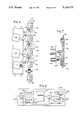
- FIG. 3is a left side elevational view of the remote wire driver of FIG. 1 with a portion broken away illustrating the placement of the active and dummy wire storage and guide channels and of wire drive assemblies and wire position detectors;
- FIG. 4is an expanded view of the wire movement apparatus of FIG. 3;
- FIG. 5is a block diagram of the wire driver control circuitry
- FIG. 6is a block diagram of a sanity timer of FIG. 5;
- FIG. 7is a sectional view taken along line 7--7 of FIG. 13 of the catheter select turret assembly
- FIG. 8is a sectional view taken along line 8--8 of FIG. 13 of the catheter select turret assembly
- FIG. 9is a rear elevational view of the rotating turret of the turret assembly.
- FIG. 10is a sectional view taken along line 10--10 of FIG. 9 of the rotating turret further illustrating the placement of a catheter connector therein;
- FIG. 11is a side elevational view of a catheter connector
- FIG. 12is a front elevational view of the catheter select turret assembly showing the catheter locking plate
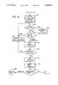
- FIG. 13is a flowchart depicting console computer operation
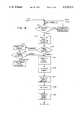
- FIGS. 14 and 15are flowcharts depicting wire driver control operation.
- FIG. 16is an alternative embodiment for a pinch roller control assembly of FIG. 4.
- the remote afterloader of the present inventionincludes a computerized control console 10 located in a control room 12 and a remote safe and delivery wire driver 14 located in a treatment room 16.
- Federal regulationsrequire, in view of the high radiation levels associated with high activity sources, that patients undergoing treatment be placed in shielded treatment rooms isolated from the attending physicians and other personnel.
- the treatment room 16complies with appropriate federal regulations for shielding and, further, is provided with an entrance door interlock 18 to automatically retract, as discussed in more detail below, the active source upon entrance of non-patient personnel into the treatment room.
- a data and control bus 20interconnects the console 10 with the remote driver 14.
- the data and control bus 20 of the present embodimentis an RS 422 link which connects console 10 to a microprocessor controlled controller 13 of wire driver 14.
- FIG. 2is a block illustration of the control console 10 which includes a computer 22 of conventional availability incorporating a color monitor 24, a keyboard 26, a printer 28 and a floppy disk drive 30. More specifically, the computer is of the well-known 80386 processor variety and includes an additional 40 M-byte hard drive.
- An uninterruptible power supply 32is provided to protect against losses of power during on-going treatment sequences. Uninterruptible power supply 32 also provides power to the wire driver 14.
- annunciators and specific control function input buttonsare also included with the console 10 of FIG. 2 .
- a similar panel of annunciators and switchesis provided at the treatment room door and at the remote wire driver. The later panels are both controlled from the wire driver controller 13.
- FIG. 3illustrates various structural features of the remote driver 14 used to extend treatment wires into a catheter 55 for patient treatment.
- the active delivery wirehas an overall length of 2.1 meters and contains a 10 millimeter long seed of activated iridium spaced 1 millimeter from the forward end thereof.
- the dummy wireis 1.8 meters in length and does not contain an iridium seed.
- the iridium seed of the active wireis typically irradiated to an activity level of 10 curies and, therefore, represents a potentially dangerous source of radiation that must be properly stored when not in use.
- a lead safe 58is provided for this purpose.
- safe 58comprises a lead sphere having a radius of approximately 106 mm.
- the safe 58is provided with a 90 degree radius cylindrical channel 60 of sufficient diameter to pass the active wire source.
- the channel 60defines a lower inlet 62 through which the active wire feeds from its guide and storage channel 66, discussed in more detail hereinafter, and an outlet 64 from which the active wire source is extended, thereafter, through a turret 56 and into the active catheter 55.
- the active and dummy wire guide channels 66 and 67are made of stainless steel tubes which are connected by connectors 80 to a backing plate 76.
- the overall length of the active channel 66is selected such that the 10 mm active portion of the active wire 90, i.e., the iridium seed, will be substantially centered in the safe 58 at its midpoint 68 when the opposed rearward wire end abuts a park switch 72 positioned at end 70 of the active channel.
- the overall length of dummy guide channel 67is selected such that the forward end of the dummy wire will be retracted to a non-interfering position 69 when the opposed rearward end thereof abuts a dummy park switch 73 at channel end 71.
- the channels 66 and 67are broadly radiused, preferably to about 80 mm, to minimize wire friction therewith.
- the respective active and dummy wire channelsmerge in a "Y" or wishbone channel connector 82, thereafter forming a single output channel 83 operatively interconnected with the turret 56.
- the wishbone connector 82is milled to the ultimate channel working dimension through which the respective active and dummy wires pass directly.
- the active wire drive and emergency retraction system 84is shown in FIG. 3 and in enlarged form in FIG. 4.
- the dummy wire drive system 86is identical, except that the emergency retract motor 113 and its drive assembly 108 is omitted.
- the uppermost capstan 94 and pinch roller 96define the stepper motor 88 wire drive assembly.
- Stepper motor 88is beneath backing plate 76 and is shown in dotted lines.
- stepper motor 88moves the active wire 90 along the previously identified path 66 in both the extension (upward) and retraction directions.
- the active wireis extended to the maximum treatment position then, as required by the prescribed treatment profile, retracted in precisely timed intervals of predetermined distance until the entire treatment cycle for the given catheter has been completed.
- the stepper motor 88 drive assemblyincludes a rubber surfaced capstan 94 which is rotated by the stepper drive motor 88.
- a rubber pinch roller 96is pivotally mounted at a pivot 98 and urges active wire 90 against the capstan 94 when pull-type solenoid 100 is energized.
- sections of the guide channel 66have been removed so that the pinch roller 96 and capstan 94 can physically contact the drive wire 90.
- the remaining sections of channel 66guide the wire 90 so that it remains substantially straight and runs parallel to the plane of capstan 94 rotation.
- the encoder drive assembly 102below the drive capstan 94 is the encoder drive assembly 102. It is substantially identical to the above described wire drive assembly except that an encoder 238 which is connected through plate 76 to an encoder shaft or capstan 104 is substituted for the stepper drive motor 88. When active pull-type solenoid 106 is energized and moves a pinch roller to engage the wire 90 with capstan 104, movement of the wire 90 rotates capstan 104. Encoder 238 responds to the rotation of capstan 104 by sending wire movement indicating pulses to controller 13 which uses the pulses to track the position of the active source in wire 90.
- This assemblydiffers from the stepper motor drive assembly in two important aspects.
- the capstan 112is driven from a conventional, non-stepper type DC motor 113.
- the pinch roller controlling solenoid 114is of the push-type and includes a spring 116 which biases a pinch roller 118 against the capstan 112. Solenoid 114 power is required to retract the pinch roller 118 thereby disengaging the wire 90 from the emergency retract capstan 112.
- emergency retraction solenoid 114In the event of a computer failure, power failure, or other system loss of control, power is dropped to emergency retraction solenoid 114, thereby automatically engaging the wire 90 with emergency retraction capstan 112, while emergency battery power is simultaneously applied to emergency retraction motor 113.
- emergency retraction solenoid 114As this is a conventional DC motor, no special control or stepping instructions are required. Emergency retraction may be effected even through other portions of the afterloader system, including the computer 22 and controller 13 are inoperative.
- emergency retraction assembly 108could be constructed using a pull-type solenoid 114' and a jointed pinch roller control arm as shown in FIG. 16.
- FIG. 16components performing the same function as in FIG. 4 are given the same reference number.
- Two over-travel optical sensorsprovide an additional level of protection and redundancy to the system
- These sensors 194 and 195are mounted along respective active and dummy wire channels 66, 67 immediately below the wire drive systems 84 and 86.
- the computer control systemis pre-programmed to accept a maximum treatment profile well below the 2100 mm length of the active wire, e.g., 1500 mm, thereby assuring that some portion of the wire will always remain adjacent the respective over-travel sensor. Therefore, the detection of a "no wire" condition by either over-travel sensor 194, 195 necessarily signifies system malfunction terminating treatment and mandating emergency active wire retraction.
- An additional optical sensor 190is placed in channel 83 to detect the presence and absence of a delivery wire.
- the home sensor 190is the index point against which source positioning is measured.
- the home sensoris used to detect when a drive wire tip passes the home sensor point both on extension and retraction.
- Sensor 190transmits signals indicating the presence or absence of a wire at the home position to control 13.
- the catheter turret 56which is shown in FIGS. 7 through 12, comprises a turret 128 (FIG. 8) retained for rotating movement between inner and outer race members 130 and 132, respectively.
- Race members 130, 132are rigidly affixed to the housing of the remote wire driver 14 and define an annular channel 134 therebetween.
- a pair of radius grooves or races 136 and 138are formed in opposed channel surfaces of the race members.
- An annular flange 140integrally formed on the perimeter of turret 128, is received within the channel 134.
- a plurality of ball-type bearings 142are seated within holes 144, which holes are evenly spaced around the turret flange. Bearings 142 travel within races 136, 138 thereby permitting the smooth rotation of the turret 128 under the computer driven control of a stepper motor 146 attached thereto.
- FIGS. 8-12Placement and locking of catheters 54 into the turret assembly 56 is best illustrated in FIGS. 8-12.
- the end of each catheteris provided with a connector 148 defined, in part, by a cylindrical extension member 150, an annular locking flange 152 and a recess 154.
- a plurality of complementary catheter receptacle holes 156are evenly spaced (FIG. 9) around a diameter of turret 128.
- Each holeincludes a region of widened diameter 158 (FIG. 10) adapted to receive a catheter locking flange 152 therein.
- a circular catheter locking plate 160is mounted adjacent the outside of the turret 128 for limited rotation with respect thereto. As shown in FIG. 12, the locking plate 160 is provided with a plurality of holes 162, with narrowed annular extensions 164, the holes having spacings corresponding to those of the catheter holes 156 in the turret. Thus, the locking plate may be rotated to admit passage and positioning of one or more catheters in the turret. Following catheter insertions, the locking plate 160 is rotated until the narrower annular extensions 164 are received within catheter connector recesses 154 thereby locking all catheters against inadvertent removal.
- the active catheter positionis defined by the uppermost hole 156 of the turret 128, so long as that hole is properly aligned immediately above the turret/stepper motor axis. In this position, a wire extended from the output channel 83 (FIG. 3) directly enters the active catheter 55 mounted adjacent thereto.
- FIG. 10illustrates the orientation of a catheter 54 in the active catheter position 55
- An optical catheter-in-place sensor 168is mounted to the fixed inner race 130, immediately above the active catheter position.
- Optical sensor 168includes an optical source, pointed downward and an optical receiver for receiving reflected light from beneath the sensor.
- the cylindrical tip member 150 of a catheter connectorextends inwardly from the turret, light from the source of optical sensor 168 will be reflected and returned to the receiver.
- a signal indicating the receipt of reflected lightis sent to control 13.
- the inside face of turret 128includes a plurality of cylindrical locking apertures 165 (FIG. 9), which are angularly spaced the same as catheter receiving holes 156, but rotated from the catheter holes by approximately 90°.
- the turret assemblyincludes a locking solenoid 351 which is structurally connected to the turret drive assembly. Solenoid 351 has a shaft 354 which is of suitable diameter to engage the holes 165. When a catheter is placed in the active position 55, solenoid 351 is energized to thrust shaft 354 into a hole 165.
- the outward end of shaft 354may be tapered to promote engagement with a hole 165 and to slightly correct the position of the active catheter.
- the assembly of FIG. 7also includes an optical sensor 352 which, by means of an aperture (not shown) in shaft 354, senses the seating of shaft 354 into turret 128. A signal representing such seating is sent from optical sensor 352 to control 13.
- Turret 56is rotationally positioned by the cooperative action of a stepper motor 146 and a rotation sensing optical encoder 353 (FIG. 3) rotationally coupled at 355 to the stepper motor.
- Encoder 353transmits to wire drive control 13 a series of signals indicative of its rotation and sends an index position signal once per 360° rotation.
- the index position signalwhich is common to rotational encoders, is used to align the components of turret 56 during assembly and to identify a "home" catheter aperture 156 at the beginning of each treatment.
- the turret shaftis rotated until the index signal is generated by encoder 353.
- the turret 128is then mounted to the shaft with a first (home) catheter hole aligned with the output of guide tube 83. Thereafter, the index signal from rotational encoder 353 is used to identify the home turret position.
- control 13sends stepper pulses to stepper motor 146 until the index signal is generated by encoder 353.
- the number of stepper control pulses between the home catheter position and the destination catheter positioncan then be sent to stepper motor 146 to achieve the proper rotation to place the destination catheter at the active location.
- the output signals from encoder 353are used by control 13 during such rotation to check the actual turret rotation accuracy.
- Treatmentbegins when an operator enters, at console computer 22, a treatment plan for a particular patient and the catheters connected to that patient are attached to the connectors 156 of turret 56.
- the treatment planspecifies which turret connectors, i.e., which catheters, are to receive treatment, the location of treatment in distance from the home sensor 190, and the length of time for each treatment.
- console computer 22runs diagnostic tests, checks the treatment plan for accuracy and safety.
- FIG. 5is a block diagram of the control circuitry included in wire driver 14.
- the message on link 20is received by controller 13 of the remote wire driver 14 which in response, performs a number diagnostic and safety tests within remote wire driver 14.
- a response messageis then returned to computer 22, indicating the success of the tests.
- Console computer 22then responds by identifying the first turret connector (catheter) which is to receive treatment.
- Wire driver 14responds to this message by checking to see that both the dummy and the active wires are in their fully withdrawn positions as indicated to control 13 by the signals from active park switch 72 and the dummy park switch 73.
- Wire driver control 13then transmits stepper motor control signals on a multi-conductor bus 411 to stepper motor 146 to first "home" the turret then place the first treatment catheter, e.g., 55 in the active position to receive the active or dummy wire from wire driver 14.
- stepper motor 146rotates the turret, the turret motion is sensed by encoder 353 and reported via bus 411 to wire driver control 13 which tracks the rotation.
- wire driver control 13transmits an activation signal to solenoid 351 which drives the locking pin 354 into place.
- Wire driver control 13then checks locking pin detector 352 and catheter present detector 168 to determine if the turret is properly locked in place and if a catheter, e.g., 55 is in the active turret position.
- the console computer 22next sends a command specifying that the non-radioactive dummy wire is to be moved to the maximum treatment distance and withdrawn.
- Wire driver control 13responds to the command by grounding dummy wire drive solenoid 403 and dummy wire encoder solenoid 407 over conductors 410 and 412, respectively, of multi-conductor bus 411.
- the other terminals of solenoids 403 and 407are permanently connected to a positive voltage supply 409 via a conductor 413. Accordingly, both solenoids 403 and 407 are energized to engage the dummy wire between their respective pinch rollers and capstans.
- Wire driver control 13also begins to transmit stepper motor control signals over communication path 415 of bus 411 to advance the dummy wire by rotating dummy wire stepper motor 230.
- stepper motor 230is commanded by wire driver control 13 to reverse and thereby retract the dummy wire.
- home sensor 190is an optical sensing means which detects when the tip of a wire, either the active wire or the dummy wire passes therethrough.
- wire driver control 13records a count called the home count which represents the wire position value when the tip of the wire passed the home sensor. As the wire continues to move into and out of the catheter, the wire position value is incremented and decremented in response to signals from encoder 405.
- Console computer 22specifies treatment positions in terms of distance from the input of the catheter (output of the wire driver).
- a known guide tube distancecalled the offset, exists between the home sensor the wire driver outlet. Due to the offset, a treatment distance specified in a command is reached when the wire movement value, minus both the home count and the offset, equals that specified treatment distance.
- the dummy wirecontinues to advance through the turret into the treatment catheter 55 until the maximum treatment distance has been reached by the tip of the dummy wire.
- Wire driver control 13then reverses the direction of rotation of stepper motor 230 to begin withdrawing the dummy wire back into wire driver unit 14.
- wire driver control 13is notified.
- the amount stored in the wire position valueshould be substantially equal to the home count which was recorded when the dummy wire interrupted sensor 190 during the wire extension operation. If these numbers are within a predetermined threshold of one another, the process is assumed to be accurate and the dummy wire continues to be withdrawn until it parks against park switch 73.
- Wire driver control 13is notified when the dummy wire changes the position of park switch 73 and ground is removed from the solenoids 403 and 407. Also, no new control signals are transmitted to stepper motor 230. After the proper operation of the treatment apparatus is determined by the extension and withdrawal of the dummy wire, wire driver control 13 is ready to perform the requested treatment using the active source wire 90. Active wire 90 movement is performed substantially as described above except that the drive apparatus 84 of the active wire is used.
- a safety relay 401is the heart of the emergency shutdown and active wire retraction system. Upon the automatic detection of any system abnormality or difficulty, or upon the manual intervention by a system operator through the actuation of a stop button, the relay 401 is immediately de-energized and remains de-energized until the cause of the problem has been corrected and the operator resets the system. When relay 401 is de-energized power is removed from the stepper motor control portion of active drive assembly 84 and retraction motor 113 is energized to withdraw the active wire 90.
- the relay 401is directly interconnected with both the emergency retraction DC motor 113 and to the emergency retraction capstan solenoid 114 thereby instantly commencing the emergency retraction cycle.
- deactivation poweris removed from the retraction solenoid 114 and power from the emergency backup battery 418 is applied to the emergency retraction motor 113.
- the emergency retraction cyclecontinues until the active wire 90 is fully retracted, as determined by wire engagement with the park switch 72.
- Relay 401includes a plurality of stationary contacts 422 and 423, a pair of movable contacts 419 and 420 and a coil 421.
- Coil 421is energized for normal operation by connection to the power supply 409 and to ground via a fault interrupter circuit 425.
- Fault interrupter 425comprises a pair of transistors with their emitter-collector paths serially connected. Both transistors, in normal operation, receive from fault control logic 429 high level signals at their bases so that low resistance path is presented from coil 421 to ground.
- relay 401When coil 421 is energized, armatures 419 and 420 of relay 401 are pulled down so that armature 419 connects power from power supply 409 to stationary contact 422 which is connected to active drive stepper motor 88, active drive enable solenoid 100, encoder 238, encoder solenoid 106 and emergency retract solenoid 114. While relay 401 remains energized, the active wire drive is capable of moving the active wire 90 as directed by wire driver control 13 and retraction solenoid 114 is energized to release any engagement with active wire 90.
- fault control logic 429removes the high level signal from the bases of one or both of the transistors 426 and 427, de-energizing relay 401.
- the armature of relay 401moves up and contact 420 touches contact 423 which is connected to the minus or ground terminal of DC retraction motor 113.
- the positive terminal of retraction motor 113is directly connected to battery 418.
- Contact 420 of relay 401is connected to ground via the normally closed contact of active wire park switch 72. Should relay 401 be de-energized while active wire 90 is extended, power is removed from the active wire stepper drive 84 including the retraction solenoid 114 and ground is applied to retraction motor 113 via relay 401 and active park switch 72.
- a timer 440is activated during each emergency retraction to time the retraction and cause an audible alarm when the retraction is not completed within approximately 30 seconds.
- Retraction timer 440is normally kept idle by the low level signal at the collector of transistor 426. When this collector goes high, as will be the case when relay 401 is de-energized, timer 440 begins to time a 30 second interval.
- the return of active wire 90 into contact with park switch 72generates a reset signal which is connected via conductor 442 to timer 440.
- the reset signal on conductor 442will clear timer 440, if it is received within the 30 second time out interval. If it is not received within the 30 second interval, a signal is sent from retract timer 440 to an alarm 441 which notifies operating personnel by means of an audible alarm signal.
- Fault control logic 429responds individually to a plurality of fault signalling conditions by removing the high level signals from the bases of transistors 426 and 427.
- the signals which result in de-energizing relay 401are signals from door open switch 18, a reset switch on the control panel of wire driver 14 (not shown) overrun detector 194, and signals requesting retraction received from control 13 on a conductor 431.
- Fault control logic 429also de-energizes relay 401 in response to signals from a pair of activity timers 124 and 126.
- timer 124monitors the ability of wire driver control 13 to function.
- Control 13transmits a periodic signal on a bus 604 approximately once every 100 milliseconds, but only when the computer hardware and software are functioning properly. If this signal is lost for more than about 100 milliseconds, the timer 124 sends a fault signal to fault control logic 429 which, in turn, releases the relay 401.
- the activity timer 124actually comprises a pair of redundant 100 millisecond timers 610 and 611 (FIG. 6). Unless reset every 100 milliseconds by signals from control 13, each timer 610 and 611 will generate a time-out signal on a respective one of conductors 612 and 613. Such time-out signals are connected to fault control logic 429 and cause de-energization of relay 401.
- the reset signals from control 13comprise 8 binary digits and a strobe signal. To constitute proper reset signals, a given reset signal must be exactly one greater than the immediately preceding reset signal.
- the 8 bit reset signal portionis received on path 609 of bus 604 and stored in a buffer 601, the outputs of which are applied to an 8 bit comparator 603.
- Timer 124also includes an 8 bit counter 602 which counts modulo 256, the incoming strobe signals which are connected to counter 602 via path 605.
- the outputs of counter 602are also applied as inputs to comparator 603 where the counter bits are compared with the contents of buffer 601.
- a logic 1 reset signalis transmitted by comparator 603 to a flip-flop 607 which buffers the reset signal and conveys it to timers 610 and 611 before they time out.
- a logic 0 signalis generated by comparator 603 and timers will transmit fault signals to fault control logic 429 when they time out.
- the counteris initially synchronized with the reset signals from control 13 by a clear signal transmitted to counter 602 on bus 604. The requirement that the 10 millisecond reset signals follow a prescribed sequence provides great assurance that control 13 is functioning properly.
- the second activity timer 126commences timing whenever the active wire 90 is extended. That is, whenever the active wire is not pressing the active park switch 72. A maximum time of about 20 minutes is allotted for active wire extension which time limit exceeds the duration of the longest treatment profile anticipated. Failure of the active wire to return to the parked position at least once every 20 minutes indicates a problem necessitating emergency active wire retraction.
- the park switch 72signals the full retraction or parking of the active wire. In the absence of the required park signal within the predetermined time limit, the timer 126 signals fault control logic 429 which releases relay 401.
- run safety relay 401provides a highly reliable means for forcing the immediate retraction of the active wire 40 in the event of computer or other failure.
- this systemis self-contained on the remote driver 14 chassis; and is of simple design thereby minimizing likelihood of failure; and incorporates backup power to further eliminate the possibility of emergency retraction failure.
- FIGS. 13 through 15illustrate overall computer controlled operation of the present remote wire afterloader system.
- a main menu 304permits optional courses of action including exiting the program 306 thereby permitting use of computer 22 for other tasks.
- Patient treatment informationincluding the proposed treatment profile, must be entered 308.
- Such profilestypically include a listing of each treatment position, by distance measured from the catheter outlet of wire driver 14, as well as the treatment dwell time at each such position.
- profile parametersmust not include treatment positions exceeding 1500 millimeters or position dwell times exceeding 60 seconds. Further, the dwell positions must be arranged in descending order and not be closer together than a predetermined distance as specified during system initialization, i.e., at 312.
- the requirement for descending order dwell positionsis important to proper operation of the present afterloader particularly in view of the extremely fine diameter wire for which the present system is intended to operate. Notwithstanding the dummy wire pretesting of each catheter to verify that an ultra-thin wire can be moved to the requisite dwell positions, there always remains some possibility than an ultra-thin wire will become jammed precluding further inward movement.
- a maintenance capability 312is accessible to qualified personnel for the purpose of source loading, unloading, calibration, and the setting of treatment profile parameter limits such as maximum dwell time and minimum dwell step sizes.
- a patient treatment record, including proposed treatment profile,is printed 314 prior to each treatment session. Actual initiation of a treatment session requires actuation of a key switch 316 by the doctor or other personnel having appropriate authority.
- the computer 22then transmits an enable treatment command to control 13.
- the control 13then performs a number of safety tests 318 (FIG. 14) in response to the enable command. Specifically, the control 13 verifies at 318 that the treatment room door is closed; that the console-to remote driver communications bus 20 is functioning; that both active and dummy wires are parked; that the wire position sensors are functioning; and, that the emergency backup battery voltage is proper.
- wire driver control 13After satisfactorily passing the tests of 318, wire driver control 13 returns a command completed or OK message to computer 22 at block 319 and awaits the next command which will be a catheter select command, specifying a catheter location.
- the turret positionis set and checked at 320 by "homing" the turret, controlling stepper motor 146 to rotate to the specified position and locking the turret 128 by the solenoid 351.
- the turretis repositioned at 322 and rechecked at 324 if the initial position is not correct.
- the turretis also checked for the presence of a catheter in the selected position.
- step 325another command complete message is sent to computer 22 and wire driver control 13 awaits a dummy position command specifying a dummy wire position in block 325.
- wire driver 14tests the first catheter position by cycling the dummy wire at 326.
- the wire driver control 13selects the dummy wire by grounding drive solenoid 403 and outputting a series of stepper motor commands sufficient to move the dummy wire approximately 5 millimeters beyond the dwell location specified for the catheter under test.
- the driver control 13first calculates the number of steps required to extend the wire to the desired maximum position (including the 5 millimeter overextension) and the corresponding number of pulses expected from the dummy wire encoder 405. These calculations are based on a reference point defined by the home optical sensor 190, located adjacent the turret. Stepping of the dummy stepper 230 motor now commences and continues until the specified dummy wire position is achieved.
- the control 13is performing cross-checks to verify that no obstructions or jams have been encountered.
- wire jamsare determined by comparing the number of encoder 405 pulses received per stepper motor step.
- this testmay be performed only after a predetermined number of steps have been taken to save computer resources. In the present embodiment, such a comparison is performed after each block of 33 stepper motor steps. If pulses stop, or fall below the expected rate, the wire is retracted and a jam condition is annunciated.
- wire driver control 13After achieving the specified dummy wire position, wire driver control 13 sends an OK signal, and awaits a retraction signal at 327. The dummy wire is fully retracted in block 328 to terminate the dummy wire test cycle. Upon retraction, the length of the dummy wire is again checked to confirm that the wire has not broken. This check is performed by comparing the stored home count with the wire movement value which should be substantially equal. The wire driver control 13 signals the successful completion of retraction to computer 22 and awaits an active wire command in block 330.
- the active wire command from computer 22specifies the maximum treatment position for the active wire.
- the active wireis then extended to the furthest treatment position at 332 (FIG. 14). Extension of the active wire is substantially identical to that of the previously described dummy wire.
- the wireis then precisely positioned at the first treatment location by, as before, first over-extending the wire by approximately 5 millimeters. Wire jamming and obstruction tests are performed again, as outlined with reference to extension of the dummy wire.
- the control 13continues to monitor system safety indices at 334, including the long term watchdog timer 126. Since the active wire is fully retracted and parked between each catheter treatment profile, this timer reflects active wire extension beyond the maximum treatment profile allowed by the computer In short, this timer flags a potentially hazardous condition necessitating emergency retraction at 336.
- Control 13Upon completion of the pre-programmed dwell time for each active wire position at 338, an OK message is sent and a new treatment position is awaited in 339. Control 13 checks to see whether there are further treatment positions for that catheter at 340, if so, the active wire is withdrawn to the specified next adjacent dwell position at 342.
- the active wireis fully retracted in 341, checking the overall wire length to confirm that the entire wire length, including the active iridium tip portion, has been properly retrieved.
- the control 13thereafter determines by communication 342 with computer 22 whether there are additional catheter treatment profiles to be run at 344. If not, a normal stop at 346 and return to the main menu of computer 22 at 304 occur.
- the flowproceeds to block 318 (FIG. 14) and the turret is repositioned and checked at 320. Prior to running each active wire treatment profile, the new catheter position is checked by the dummy wire at 326 as previously described.
Landscapes
- Health & Medical Sciences (AREA)
- Engineering & Computer Science (AREA)
- Biomedical Technology (AREA)
- Pathology (AREA)
- Nuclear Medicine, Radiotherapy & Molecular Imaging (AREA)
- Radiology & Medical Imaging (AREA)
- Life Sciences & Earth Sciences (AREA)
- Animal Behavior & Ethology (AREA)
- General Health & Medical Sciences (AREA)
- Public Health (AREA)
- Veterinary Medicine (AREA)
- Infusion, Injection, And Reservoir Apparatuses (AREA)
- Radiation-Therapy Devices (AREA)
Abstract
Description
Claims (7)
Priority Applications (1)
| Application Number | Priority Date | Filing Date | Title |
|---|---|---|---|
| US07/753,192US5139473A (en) | 1990-10-12 | 1991-08-30 | Apparatus and method for the remote handling of highly radioactive sources in the treatment of cancer |
Applications Claiming Priority (2)
| Application Number | Priority Date | Filing Date | Title |
|---|---|---|---|
| US07/596,928US5092834A (en) | 1990-10-12 | 1990-10-12 | Apparatus and method for the remote handling of highly radioactive sources in the treatment of cancer |
| US07/753,192US5139473A (en) | 1990-10-12 | 1991-08-30 | Apparatus and method for the remote handling of highly radioactive sources in the treatment of cancer |
Related Parent Applications (1)
| Application Number | Title | Priority Date | Filing Date |
|---|---|---|---|
| US07/596,928DivisionUS5092834A (en) | 1990-10-12 | 1990-10-12 | Apparatus and method for the remote handling of highly radioactive sources in the treatment of cancer |
Publications (1)
| Publication Number | Publication Date |
|---|---|
| US5139473Atrue US5139473A (en) | 1992-08-18 |
Family
ID=24389313
Family Applications (2)
| Application Number | Title | Priority Date | Filing Date |
|---|---|---|---|
| US07/596,928Expired - LifetimeUS5092834A (en) | 1990-10-12 | 1990-10-12 | Apparatus and method for the remote handling of highly radioactive sources in the treatment of cancer |
| US07/753,192Expired - LifetimeUS5139473A (en) | 1990-10-12 | 1991-08-30 | Apparatus and method for the remote handling of highly radioactive sources in the treatment of cancer |
Family Applications Before (1)
| Application Number | Title | Priority Date | Filing Date |
|---|---|---|---|
| US07/596,928Expired - LifetimeUS5092834A (en) | 1990-10-12 | 1990-10-12 | Apparatus and method for the remote handling of highly radioactive sources in the treatment of cancer |
Country Status (1)
| Country | Link |
|---|---|
| US (2) | US5092834A (en) |
Cited By (62)
| Publication number | Priority date | Publication date | Assignee | Title |
|---|---|---|---|---|
| US5600785A (en)* | 1994-09-09 | 1997-02-04 | Compaq Computer Corporation | Computer system with error handling before reset |
| US5800333A (en)* | 1996-02-20 | 1998-09-01 | United States Surgical Corporation | Afterloader provided with remote control unit |
| WO1999001174A1 (en)* | 1997-07-03 | 1999-01-14 | Guidant Corporation | Compact cartridge for afterloader and method |
| US5882290A (en)* | 1996-02-29 | 1999-03-16 | Scimed Life Systems, Inc. | Intravascular radiation delivery system |
| US5957829A (en)* | 1997-12-17 | 1999-09-28 | Advanced Cardiovascular Systems, Inc. | Apparatus and method for radiotherapy using a radioactive source wire having a magnetic insert |
| US5997462A (en)* | 1998-01-08 | 1999-12-07 | Delft Instruments Intellectual Property B.V. | Method and apparatus for treating a blood vessel lesion |
| US6019718A (en)* | 1997-05-30 | 2000-02-01 | Scimed Life Systems, Inc. | Apparatus for intravascular radioactive treatment |
| US6036631A (en)* | 1998-03-09 | 2000-03-14 | Urologix, Inc. | Device and method for intracavitary cancer treatment |
| US6059812A (en)* | 1997-03-21 | 2000-05-09 | Schneider (Usa) Inc. | Self-expanding medical device for centering radioactive treatment sources in body vessels |
| US6059713A (en)* | 1997-03-06 | 2000-05-09 | Scimed Life Systems, Inc. | Catheter system having tubular radiation source with movable guide wire |
| US6074338A (en)* | 1993-07-01 | 2000-06-13 | Schneider (Europe) A.G. | Medical appliances for the treatment of blood vessels by means of ionizing radiation |
| US6099454A (en)* | 1996-02-29 | 2000-08-08 | Scimed Life Systems, Inc. | Perfusion balloon and radioactive wire delivery system |
| WO2000048661A1 (en)* | 1999-02-16 | 2000-08-24 | Cordis Corporation | Manual ribbon delivery system for intravascular radiation therapy |
| US6110097A (en)* | 1997-03-06 | 2000-08-29 | Scimed Life Systems, Inc. | Perfusion balloon catheter with radioactive source |
| US6137114A (en)* | 1995-07-15 | 2000-10-24 | Isotopen-Technik | Irradiation apparatus |
| US6146322A (en)* | 1995-12-05 | 2000-11-14 | Schneider (Europe) Ag | Irradiating filament and method of making same |
| JP2001046531A (en)* | 1999-07-23 | 2001-02-20 | Nucletron Bv | Device and method to embed radioactive seed |
| US6203485B1 (en) | 1999-10-07 | 2001-03-20 | Scimed Life Systems, Inc. | Low attenuation guide wire for intravascular radiation delivery |
| US6231494B1 (en) | 1994-06-10 | 2001-05-15 | Schneider (Europe) A.G. | Medical device with radiation source |
| US6234951B1 (en) | 1996-02-29 | 2001-05-22 | Scimed Life Systems, Inc. | Intravascular radiation delivery system |
| US6258019B1 (en) | 1997-09-26 | 2001-07-10 | Scimed Life Systems, Inc. | Catheter for intraluminal treatment of a vessel segment with ionizing radiation |
| US6264596B1 (en) | 1997-11-03 | 2001-07-24 | Meadox Medicals, Inc. | In-situ radioactive medical device |
| US6302865B1 (en) | 2000-03-13 | 2001-10-16 | Scimed Life Systems, Inc. | Intravascular guidewire with perfusion lumen |
| US6350227B1 (en) | 1997-09-23 | 2002-02-26 | Interventional Therapies, Llc | Afterloader apparatus |
| US6352501B1 (en) | 1999-09-23 | 2002-03-05 | Scimed Life Systems, Inc. | Adjustable radiation source |
| US6352500B1 (en) | 1999-09-13 | 2002-03-05 | Isotron, Inc. | Neutron brachytherapy device and method |
| US6398708B1 (en) | 1996-02-29 | 2002-06-04 | Scimed Life Systems, Inc. | Perfusion balloon and radioactive wire delivery system |
| US6398709B1 (en) | 1999-10-19 | 2002-06-04 | Scimed Life Systems, Inc. | Elongated member for intravascular delivery of radiation |
| WO2001093945A3 (en)* | 2000-06-05 | 2002-06-20 | Mentor Corp | Automated radioisotope seed cartridge |
| US6413203B1 (en) | 1998-09-16 | 2002-07-02 | Scimed Life Systems, Inc. | Method and apparatus for positioning radioactive fluids within a body lumen |
| US6416457B1 (en) | 2000-03-09 | 2002-07-09 | Scimed Life Systems, Inc. | System and method for intravascular ionizing tandem radiation therapy |
| US6419625B1 (en) | 1997-01-03 | 2002-07-16 | Robin G. Smith | Methods and devices for ex vivo irradiation of autologous coronary bypass conduit |
| US20020099255A1 (en)* | 1997-09-23 | 2002-07-25 | Liprie Sam F. | Afterloader apparatus |
| US6497645B1 (en) | 2000-08-28 | 2002-12-24 | Isotron, Inc. | Remote afterloader |
| US20030018232A1 (en)* | 2000-06-05 | 2003-01-23 | Mentor Corporation | Automated implantation system for radioisotope seeds |
| US6561966B1 (en)* | 1999-06-04 | 2003-05-13 | Radi Medical Technologies Ab | Device for X-ray dosage control |
| US6616629B1 (en) | 1994-06-24 | 2003-09-09 | Schneider (Europe) A.G. | Medical appliance with centering balloon |
| US6635008B1 (en) | 1997-03-11 | 2003-10-21 | Interventional Therapies Llc | System and method for delivering a medical treatment to a treatment site |
| US6641519B1 (en)* | 1999-07-23 | 2003-11-04 | Nucletron B.V. | Wire drive in a medical device |
| US6676590B1 (en) | 1997-03-06 | 2004-01-13 | Scimed Life Systems, Inc. | Catheter system having tubular radiation source |
| US20040010301A1 (en)* | 2002-07-11 | 2004-01-15 | Johann Kindlein | Urethral probe device |
| US6685619B2 (en) | 1999-09-13 | 2004-02-03 | Isotron, Inc. | Methods for treating solid tumors using neutron therapy |
| US6817995B1 (en) | 2000-04-20 | 2004-11-16 | Isotron ,Inc. | Reinforced catheter connector and system |
| EP1593408A1 (en)* | 2004-05-06 | 2005-11-09 | Isodose Control B.V. | Apparatus for transporting and positioning a capsule, in which a radioactive source is present |
| WO2006027254A1 (en)* | 2004-09-10 | 2006-03-16 | Anwer Puthawala | Recharge device for brachytherapy of tumours |
| WO2006027253A1 (en)* | 2004-09-10 | 2006-03-16 | Anwer Puthawala | Device for brachytherapy with at least one radiation source for introduction into the body |
| US20060135843A1 (en)* | 2004-12-20 | 2006-06-22 | Christopher Heath | Method and apparatus for automatic tracking and identification of device components |
| US20070276216A1 (en)* | 2004-08-16 | 2007-11-29 | Refael Beyar | Image-Guided Navigation for Catheter-Based Interventions |
| JP2008200531A (en)* | 2000-11-14 | 2008-09-04 | Medi-Physics Inc | Device for loading radioactive seed |
| US20090131955A1 (en)* | 2005-09-29 | 2009-05-21 | Corindus Ltd. | Methods and apparatuses for treatment of hollow organs |
| US20090221958A1 (en)* | 2005-05-10 | 2009-09-03 | Rafael Beyar | User interface for remote control catheterization |
| WO2009137410A1 (en)* | 2008-05-06 | 2009-11-12 | Corindus Ltd. | Catheter system |
| US20110144658A1 (en)* | 2008-08-29 | 2011-06-16 | Corindus Inc. | Catheter simulation and assistance system |
| US20110152882A1 (en)* | 2008-08-29 | 2011-06-23 | Corindus Inc. | Catheter control system and graphical user interface |
| US20110238082A1 (en)* | 2008-12-12 | 2011-09-29 | Corindus Inc. | Remote catheter procedure system |
| US8790297B2 (en) | 2009-03-18 | 2014-07-29 | Corindus, Inc. | Remote catheter system with steerable catheter |
| US9220568B2 (en) | 2009-10-12 | 2015-12-29 | Corindus Inc. | Catheter system with percutaneous device movement algorithm |
| US9833293B2 (en) | 2010-09-17 | 2017-12-05 | Corindus, Inc. | Robotic catheter system |
| US9962229B2 (en) | 2009-10-12 | 2018-05-08 | Corindus, Inc. | System and method for navigating a guide wire |
| US10589066B2 (en) | 2012-12-31 | 2020-03-17 | Clearstream Technologies Limited | Counting apparatus for use in interventional procedures |
| US11918314B2 (en) | 2009-10-12 | 2024-03-05 | Corindus, Inc. | System and method for navigating a guide wire |
| RU2817310C1 (en)* | 2023-05-29 | 2024-04-15 | Общество с ограниченной ответственностью "РАДИАЦИОННАЯ ТЕХНИКА" | Element position counter |
Families Citing this family (19)
| Publication number | Priority date | Publication date | Assignee | Title |
|---|---|---|---|---|
| BE1009309A6 (en)* | 1995-05-02 | 1997-02-04 | Nomet Management Serv Bv | Spotlight resources loading different interstitial for brachytherapy. |
| US5851172A (en)* | 1995-05-08 | 1998-12-22 | Omnitron International, Inc. | Afterloader with active force feedback |
| US5713828A (en)* | 1995-11-27 | 1998-02-03 | International Brachytherapy S.A | Hollow-tube brachytherapy device |
| US5951458A (en)* | 1996-02-29 | 1999-09-14 | Scimed Life Systems, Inc. | Local application of oxidizing agents to prevent restenosis |
| EP0927060B1 (en)* | 1996-09-23 | 2009-04-01 | Best Vascular, Inc. | Intraluminal radiation treatment system |
| US5873811A (en)* | 1997-01-10 | 1999-02-23 | Sci-Med Life Systems | Composition containing a radioactive component for treatment of vessel wall |
| US6179766B1 (en) | 1999-01-28 | 2001-01-30 | Gregg A. Dickerson | Methods of breast cancer treatment |
| US6733500B2 (en)* | 2000-03-31 | 2004-05-11 | Medtronic, Inc. | Method and system for delivering a medical electrical lead within a venous system |
| US7497844B2 (en)* | 2000-03-31 | 2009-03-03 | Medtronic, Inc. | System and method for positioning implantable medical devices within coronary veins |
| US6537192B1 (en) | 2000-06-05 | 2003-03-25 | Mentor Corporation | Automated radioisotope seed loader system for implant needles |
| ES2256407T3 (en)* | 2002-10-07 | 2006-07-16 | Nucletron B.V. | DEVICE FOR IMPLEMENTING A SERIES OF RADIOACTIVE SEEDS AND NON-RADIOACTIVE SPACERS. |
| US20070270627A1 (en)* | 2005-12-16 | 2007-11-22 | North American Scientific | Brachytherapy apparatus for asymmetrical body cavities |
| NL1031751C2 (en)* | 2006-05-04 | 2007-11-06 | Isodose Control Intellectual P | Method for locating a source in a body. |
| US8317674B2 (en) | 2008-06-11 | 2012-11-27 | Bracco Diagnostics Inc. | Shielding assemblies for infusion systems |
| SG183085A1 (en) | 2008-06-11 | 2012-08-30 | Bracco Diagnostics Inc | Shielding assemblies for infusion systems |
| CN103458965A (en)* | 2011-03-24 | 2013-12-18 | 皇家飞利浦有限公司 | Apparatus and method for electronic brachytherapy |
| AU2017332260B2 (en) | 2016-09-20 | 2022-10-20 | Bracco Diagnostics Inc. | Radioisotope delivery system with multiple detectors to detect gamma and beta emissions |
| KR102733368B1 (en) | 2018-03-28 | 2024-11-21 | 브라코 다이어그노스틱스 아이엔씨. | Early detection of end-of-life of radioisotope generators |
| DK3776598T3 (en) | 2018-03-28 | 2022-08-01 | Bracco Diagnostics Inc | SYSTEMS AND TECHNIQUES FOR CALIBRATION OF RADIOISOTOPE DELIVERY SYSTEMS USING A GAMMA DETECTOR |
Citations (2)
| Publication number | Priority date | Publication date | Assignee | Title |
|---|---|---|---|---|
| US4969863A (en)* | 1988-10-28 | 1990-11-13 | Eric van't Hooft | Adaptor for remote after-loading apparatus for radiotherapy |
| US5030194A (en)* | 1986-07-10 | 1991-07-09 | Eric van't Hooft | Method and apparatus for effecting radioactive therapy in an animal body |
Family Cites Families (30)
| Publication number | Priority date | Publication date | Assignee | Title |
|---|---|---|---|---|
| US1753287A (en)* | 1925-05-15 | 1930-04-08 | Failla Gioacchino | Method and means for applying radium emanation |
| US1954868A (en)* | 1929-12-18 | 1934-04-17 | Failla Gioacchino | Method and means for treatment by radiations |
| US1953915A (en)* | 1931-10-22 | 1934-04-03 | Una Welding & Bonding Company | Welding rod conduit |
| US2322902A (en)* | 1940-06-01 | 1943-06-29 | Wappler Frederick Charles | Apparatus for making tubular bodies |
| US2546761A (en)* | 1950-01-13 | 1951-03-27 | Radium Chemical Company Inc | Radium nasopharyngeal applicator |
| US2798164A (en)* | 1954-04-20 | 1957-07-02 | Untermyer Samuel | Portable X-ray or gamma source |
| US2904272A (en)* | 1955-02-18 | 1959-09-15 | John P Henebry | Reel assembly |
| GB857992A (en)* | 1959-07-25 | 1961-01-04 | Willy Buesch | Apparatus for the radio-active radiation treatment of the inner cavities of a body |
| US3060924A (en)* | 1960-06-01 | 1962-10-30 | Joseph C Rush | Apparatus for application of radioactive substance to pelvic cancer |
| US3438365A (en)* | 1965-03-01 | 1969-04-15 | United Aircraft Corp | Radioactive seed containing xenon gas for medical treatment |
| US3485234A (en)* | 1966-04-13 | 1969-12-23 | Cordis Corp | Tubular products and method of making same |
| US3612058A (en)* | 1968-04-17 | 1971-10-12 | Electro Catheter Corp | Catheter stylets |
| SE318971B (en)* | 1968-05-02 | 1969-12-22 | Atomenergi Ab | |
| FR2033653A5 (en)* | 1969-02-28 | 1970-12-04 | Commissariat Energie Atomique | |
| DE1945015A1 (en)* | 1969-09-05 | 1971-03-11 | Kurt Dr Sauerwein | Device for medical treatment with radiation from radioactive substances |
| US3749086A (en)* | 1972-07-24 | 1973-07-31 | Medical Evaluation Devices & I | Spring guide with flexible distal tip |
| US3924632A (en)* | 1972-12-07 | 1975-12-09 | William A Cook | Fiber glass reinforced catheter |
| FR2348714A1 (en)* | 1976-04-20 | 1977-11-18 | Cgr Mev | CURIETHERAPY DEVICE |
| US4096862A (en)* | 1976-05-17 | 1978-06-27 | Deluca Salvatore A | Locating of tubes in the human body |
| US4190461A (en)* | 1978-03-20 | 1980-02-26 | Alpha-Omega Services, Inc. | Method for removing metallic seeds from nylon tubing used in interstitial brachytherapy |
| US4425919A (en)* | 1981-07-27 | 1984-01-17 | Raychem Corporation | Torque transmitting catheter apparatus |
| CA1197631A (en)* | 1982-07-21 | 1985-12-03 | Henry P.J. Webb | Radiotherapy apparatus |
| DE3313857A1 (en)* | 1983-04-16 | 1984-10-25 | Sauerwein, Kurt, Dr., 5657 Haan | PIPE DIVERTER |
| US4554929A (en)* | 1983-07-13 | 1985-11-26 | Advanced Cardiovascular Systems, Inc. | Catheter guide wire with short spring tip and method of using the same |
| DE3335438C2 (en)* | 1983-09-30 | 1985-09-05 | Sauerwein, Kurt, Dr., 5657 Haan | Radiation treatment device |
| US4538622A (en)* | 1983-11-10 | 1985-09-03 | Advanced Cardiovascular Systems, Inc. | Guide wire for catheters |
| US4584991A (en)* | 1983-12-15 | 1986-04-29 | Tokita Kenneth M | Medical device for applying therapeutic radiation |
| NL8400108A (en)* | 1984-01-12 | 1985-08-01 | Hooft Eric T | METHOD AND APPARATUS FOR TREATING A BODY PART WITH RADIOACTIVE MATERIAL |
| US4819618A (en)* | 1986-08-18 | 1989-04-11 | Liprie Sam F | Iridium/platinum implant, method of encapsulation, and method of implantation |
| US4861520A (en)* | 1988-10-28 | 1989-08-29 | Eric van't Hooft | Capsule for radioactive source |
- 1990
- 1990-10-12USUS07/596,928patent/US5092834A/ennot_activeExpired - Lifetime
- 1991
- 1991-08-30USUS07/753,192patent/US5139473A/ennot_activeExpired - Lifetime
Patent Citations (2)
| Publication number | Priority date | Publication date | Assignee | Title |
|---|---|---|---|---|
| US5030194A (en)* | 1986-07-10 | 1991-07-09 | Eric van't Hooft | Method and apparatus for effecting radioactive therapy in an animal body |
| US4969863A (en)* | 1988-10-28 | 1990-11-13 | Eric van't Hooft | Adaptor for remote after-loading apparatus for radiotherapy |
Cited By (110)
| Publication number | Priority date | Publication date | Assignee | Title |
|---|---|---|---|---|
| US6074338A (en)* | 1993-07-01 | 2000-06-13 | Schneider (Europe) A.G. | Medical appliances for the treatment of blood vessels by means of ionizing radiation |
| US6514191B1 (en) | 1993-07-01 | 2003-02-04 | Schneider (Europe) A.G. | Medical appliances for the treatment of blood vessels by means of ionizing radiation |
| US6582352B2 (en) | 1994-06-10 | 2003-06-24 | Schneider (Europe) A.G. | Medical appliance for treatment by ionizing radiation |
| US6231494B1 (en) | 1994-06-10 | 2001-05-15 | Schneider (Europe) A.G. | Medical device with radiation source |
| US6616629B1 (en) | 1994-06-24 | 2003-09-09 | Schneider (Europe) A.G. | Medical appliance with centering balloon |
| US6061810A (en)* | 1994-09-09 | 2000-05-09 | Compaq Computer Corporation | Computer system with error handling before reset |
| US5600785A (en)* | 1994-09-09 | 1997-02-04 | Compaq Computer Corporation | Computer system with error handling before reset |
| US6137114A (en)* | 1995-07-15 | 2000-10-24 | Isotopen-Technik | Irradiation apparatus |
| US6146322A (en)* | 1995-12-05 | 2000-11-14 | Schneider (Europe) Ag | Irradiating filament and method of making same |
| US5800333A (en)* | 1996-02-20 | 1998-09-01 | United States Surgical Corporation | Afterloader provided with remote control unit |
| US6599230B2 (en) | 1996-02-29 | 2003-07-29 | Scimed Life Systems, Inc. | Intravascular radiation delivery system |
| US5882290A (en)* | 1996-02-29 | 1999-03-16 | Scimed Life Systems, Inc. | Intravascular radiation delivery system |
| US6099454A (en)* | 1996-02-29 | 2000-08-08 | Scimed Life Systems, Inc. | Perfusion balloon and radioactive wire delivery system |
| US6398708B1 (en) | 1996-02-29 | 2002-06-04 | Scimed Life Systems, Inc. | Perfusion balloon and radioactive wire delivery system |
| US6234951B1 (en) | 1996-02-29 | 2001-05-22 | Scimed Life Systems, Inc. | Intravascular radiation delivery system |
| US6419625B1 (en) | 1997-01-03 | 2002-07-16 | Robin G. Smith | Methods and devices for ex vivo irradiation of autologous coronary bypass conduit |
| US6575898B2 (en) | 1997-01-03 | 2003-06-10 | Emory University | Methods and devices for ex vivo irradiation of autologous coronary bypass conduit |
| US6117065A (en)* | 1997-03-06 | 2000-09-12 | Scimed Life Systems, Inc. | Perfusion balloon catheter with radioactive source |
| US6110097A (en)* | 1997-03-06 | 2000-08-29 | Scimed Life Systems, Inc. | Perfusion balloon catheter with radioactive source |
| US6059713A (en)* | 1997-03-06 | 2000-05-09 | Scimed Life Systems, Inc. | Catheter system having tubular radiation source with movable guide wire |
| US6676590B1 (en) | 1997-03-06 | 2004-01-13 | Scimed Life Systems, Inc. | Catheter system having tubular radiation source |
| US6635008B1 (en) | 1997-03-11 | 2003-10-21 | Interventional Therapies Llc | System and method for delivering a medical treatment to a treatment site |
| US6059812A (en)* | 1997-03-21 | 2000-05-09 | Schneider (Usa) Inc. | Self-expanding medical device for centering radioactive treatment sources in body vessels |
| US6267775B1 (en) | 1997-03-21 | 2001-07-31 | Schneider (Usa) Inc. | Self-expanding medical device for centering radioactive treatment sources in body vessels |
| US6019718A (en)* | 1997-05-30 | 2000-02-01 | Scimed Life Systems, Inc. | Apparatus for intravascular radioactive treatment |
| US6422989B1 (en) | 1997-05-30 | 2002-07-23 | Scimed Life Systems, Inc. | Method for intravascular radioactive treatment |
| WO1999001174A1 (en)* | 1997-07-03 | 1999-01-14 | Guidant Corporation | Compact cartridge for afterloader and method |
| US20020099255A1 (en)* | 1997-09-23 | 2002-07-25 | Liprie Sam F. | Afterloader apparatus |
| EP1331971A4 (en)* | 1997-09-23 | 2006-03-08 | Interventional Therapies Llc | Afterloader apparatus |
| US6350227B1 (en) | 1997-09-23 | 2002-02-26 | Interventional Therapies, Llc | Afterloader apparatus |
| US6258019B1 (en) | 1997-09-26 | 2001-07-10 | Scimed Life Systems, Inc. | Catheter for intraluminal treatment of a vessel segment with ionizing radiation |
| US6264596B1 (en) | 1997-11-03 | 2001-07-24 | Meadox Medicals, Inc. | In-situ radioactive medical device |
| US5957829A (en)* | 1997-12-17 | 1999-09-28 | Advanced Cardiovascular Systems, Inc. | Apparatus and method for radiotherapy using a radioactive source wire having a magnetic insert |
| US5997462A (en)* | 1998-01-08 | 1999-12-07 | Delft Instruments Intellectual Property B.V. | Method and apparatus for treating a blood vessel lesion |
| US6036631A (en)* | 1998-03-09 | 2000-03-14 | Urologix, Inc. | Device and method for intracavitary cancer treatment |
| US6413203B1 (en) | 1998-09-16 | 2002-07-02 | Scimed Life Systems, Inc. | Method and apparatus for positioning radioactive fluids within a body lumen |
| WO2000048661A1 (en)* | 1999-02-16 | 2000-08-24 | Cordis Corporation | Manual ribbon delivery system for intravascular radiation therapy |
| US6575891B1 (en) | 1999-02-16 | 2003-06-10 | Cordis Corporation | Manual ribbon delivery system for intravascular radiation therapy |
| US6561966B1 (en)* | 1999-06-04 | 2003-05-13 | Radi Medical Technologies Ab | Device for X-ray dosage control |
| EP1070519B1 (en)* | 1999-07-23 | 2005-08-10 | Nucletron B.V. | Device and method for loading radioactive seeds in needles |
| US6454696B1 (en)* | 1999-07-23 | 2002-09-24 | Nucletron B. V. | Device and method for implanting radioactive seeds |
| JP2001046531A (en)* | 1999-07-23 | 2001-02-20 | Nucletron Bv | Device and method to embed radioactive seed |
| US6641519B1 (en)* | 1999-07-23 | 2003-11-04 | Nucletron B.V. | Wire drive in a medical device |
| US6770021B2 (en) | 1999-09-13 | 2004-08-03 | Isotron, Inc. | Neutron brachytherapy device and method |
| US6685619B2 (en) | 1999-09-13 | 2004-02-03 | Isotron, Inc. | Methods for treating solid tumors using neutron therapy |
| US6352500B1 (en) | 1999-09-13 | 2002-03-05 | Isotron, Inc. | Neutron brachytherapy device and method |
| US6352501B1 (en) | 1999-09-23 | 2002-03-05 | Scimed Life Systems, Inc. | Adjustable radiation source |
| US6203485B1 (en) | 1999-10-07 | 2001-03-20 | Scimed Life Systems, Inc. | Low attenuation guide wire for intravascular radiation delivery |
| US6398709B1 (en) | 1999-10-19 | 2002-06-04 | Scimed Life Systems, Inc. | Elongated member for intravascular delivery of radiation |
| US6416457B1 (en) | 2000-03-09 | 2002-07-09 | Scimed Life Systems, Inc. | System and method for intravascular ionizing tandem radiation therapy |
| US6302865B1 (en) | 2000-03-13 | 2001-10-16 | Scimed Life Systems, Inc. | Intravascular guidewire with perfusion lumen |
| US6817995B1 (en) | 2000-04-20 | 2004-11-16 | Isotron ,Inc. | Reinforced catheter connector and system |
| US6869390B2 (en) | 2000-06-05 | 2005-03-22 | Mentor Corporation | Automated implantation system for radioisotope seeds |
| US6599231B1 (en) | 2000-06-05 | 2003-07-29 | Mentor Corporation | Loading clip for radioisotope seeds |
| WO2001093945A3 (en)* | 2000-06-05 | 2002-06-20 | Mentor Corp | Automated radioisotope seed cartridge |
| US6616593B1 (en) | 2000-06-05 | 2003-09-09 | Mentor Corporation | Automated radioisotope seed cartridge |
| US20030018232A1 (en)* | 2000-06-05 | 2003-01-23 | Mentor Corporation | Automated implantation system for radioisotope seeds |
| US20050209499A1 (en)* | 2000-06-05 | 2005-09-22 | Mentor Corporation | Automated implantation system for radioisotope seeds |
| US7959548B2 (en) | 2000-06-05 | 2011-06-14 | Core Oncology, Inc. | Automated implantation system for radioisotope seeds |
| US6497645B1 (en) | 2000-08-28 | 2002-12-24 | Isotron, Inc. | Remote afterloader |
| JP2008200531A (en)* | 2000-11-14 | 2008-09-04 | Medi-Physics Inc | Device for loading radioactive seed |
| US20040010301A1 (en)* | 2002-07-11 | 2004-01-15 | Johann Kindlein | Urethral probe device |
| US7507197B2 (en)* | 2002-07-11 | 2009-03-24 | Nucletron B.V. | Urethral prove device for effecting radiation treatment |
| US8273007B2 (en) | 2004-05-06 | 2012-09-25 | Nucletron Operations B.V. | Apparatus for transporting and positioning a capsule in which a radioactive source is present |
| EP1593408A1 (en)* | 2004-05-06 | 2005-11-09 | Isodose Control B.V. | Apparatus for transporting and positioning a capsule, in which a radioactive source is present |
| US20100305388A1 (en)* | 2004-05-06 | 2010-12-02 | Isodose Control B.V. | Apparatus for Transporting and Positioning a Capsule in which a Radioactive Source is Present |
| US8600477B2 (en) | 2004-08-16 | 2013-12-03 | Corinduc, Inc. | Image-guided navigation for catheter-based interventions |
| US20070276216A1 (en)* | 2004-08-16 | 2007-11-29 | Refael Beyar | Image-Guided Navigation for Catheter-Based Interventions |
| WO2006027254A1 (en)* | 2004-09-10 | 2006-03-16 | Anwer Puthawala | Recharge device for brachytherapy of tumours |
| WO2006027253A1 (en)* | 2004-09-10 | 2006-03-16 | Anwer Puthawala | Device for brachytherapy with at least one radiation source for introduction into the body |
| US20080221381A1 (en)* | 2004-09-10 | 2008-09-11 | Anwer Puthawala | Recharge Device for Brachytherapy of Tumors |
| US7722521B2 (en)* | 2004-12-20 | 2010-05-25 | Varian Medical Systems Uk Limited | Method and apparatus for automatic tracking and identification of device components |
| US20060135843A1 (en)* | 2004-12-20 | 2006-06-22 | Christopher Heath | Method and apparatus for automatic tracking and identification of device components |
| US8449440B2 (en) | 2004-12-20 | 2013-05-28 | Varian Medical Systems Uk Limited | Apparatus for automatic tracking and identification of device components |
| US20090221958A1 (en)* | 2005-05-10 | 2009-09-03 | Rafael Beyar | User interface for remote control catheterization |
| US8257302B2 (en) | 2005-05-10 | 2012-09-04 | Corindus, Inc. | User interface for remote control catheterization |
| US20090131955A1 (en)* | 2005-09-29 | 2009-05-21 | Corindus Ltd. | Methods and apparatuses for treatment of hollow organs |
| US9168356B2 (en) | 2008-05-06 | 2015-10-27 | Corindus Inc. | Robotic catheter system |
| US20100076308A1 (en)* | 2008-05-06 | 2010-03-25 | Corindus Ltd. | Catheter system |
| US10342953B2 (en) | 2008-05-06 | 2019-07-09 | Corindus, Inc. | Robotic catheter system |
| US10987491B2 (en) | 2008-05-06 | 2021-04-27 | Corindus, Inc. | Robotic catheter system |
| JP2011519678A (en)* | 2008-05-06 | 2011-07-14 | コリンダス インコーポレイテッド | Catheter system |
| US11717645B2 (en) | 2008-05-06 | 2023-08-08 | Corindus, Inc. | Robotic catheter system |
| WO2009137410A1 (en)* | 2008-05-06 | 2009-11-12 | Corindus Ltd. | Catheter system |
| US20100069833A1 (en)* | 2008-05-06 | 2010-03-18 | Corindus Ltd. | Catheter system |
| USD680645S1 (en) | 2008-05-06 | 2013-04-23 | Corindus Inc. | Catheter system cassette |
| US20100076310A1 (en)* | 2008-05-06 | 2010-03-25 | Corindus Ltd. | Catheter system |
| US8480618B2 (en) | 2008-05-06 | 2013-07-09 | Corindus Inc. | Catheter system |
| US7887549B2 (en) | 2008-05-06 | 2011-02-15 | Corindus Inc. | Catheter system |
| US9623209B2 (en) | 2008-05-06 | 2017-04-18 | Corindus, Inc. | Robotic catheter system |
| US20100076309A1 (en)* | 2008-05-06 | 2010-03-25 | Corindus Ltd. | Catheter system |
| US8828021B2 (en) | 2008-05-06 | 2014-09-09 | Corindus, Inc. | Catheter system |
| US9095681B2 (en) | 2008-05-06 | 2015-08-04 | Corindus Inc. | Catheter system |
| US9402977B2 (en) | 2008-05-06 | 2016-08-02 | Corindus Inc. | Catheter system |
| US8694157B2 (en) | 2008-08-29 | 2014-04-08 | Corindus, Inc. | Catheter control system and graphical user interface |
| US20110152882A1 (en)* | 2008-08-29 | 2011-06-23 | Corindus Inc. | Catheter control system and graphical user interface |
| US20110144658A1 (en)* | 2008-08-29 | 2011-06-16 | Corindus Inc. | Catheter simulation and assistance system |
| US12171955B2 (en) | 2008-12-12 | 2024-12-24 | Siemens Healthineers Endovascular Robotics Inc | Remote catheter procedure system |
| US10561821B2 (en) | 2008-12-12 | 2020-02-18 | Corindus, Inc. | Remote catheter procedure system |
| US9545497B2 (en) | 2008-12-12 | 2017-01-17 | Corindus, Inc. | Remote catheter procedure system |
| US20110238082A1 (en)* | 2008-12-12 | 2011-09-29 | Corindus Inc. | Remote catheter procedure system |
| US8790297B2 (en) | 2009-03-18 | 2014-07-29 | Corindus, Inc. | Remote catheter system with steerable catheter |
| US10881474B2 (en) | 2009-10-12 | 2021-01-05 | Corindus, Inc. | System and method for navigating a guide wire |
| US9962229B2 (en) | 2009-10-12 | 2018-05-08 | Corindus, Inc. | System and method for navigating a guide wire |
| US11696808B2 (en) | 2009-10-12 | 2023-07-11 | Corindus, Inc. | System and method for navigating a guide wire |
| US11918314B2 (en) | 2009-10-12 | 2024-03-05 | Corindus, Inc. | System and method for navigating a guide wire |
| US9220568B2 (en) | 2009-10-12 | 2015-12-29 | Corindus Inc. | Catheter system with percutaneous device movement algorithm |
| US9833293B2 (en) | 2010-09-17 | 2017-12-05 | Corindus, Inc. | Robotic catheter system |
| US10589066B2 (en) | 2012-12-31 | 2020-03-17 | Clearstream Technologies Limited | Counting apparatus for use in interventional procedures |
| RU2817310C1 (en)* | 2023-05-29 | 2024-04-15 | Общество с ограниченной ответственностью "РАДИАЦИОННАЯ ТЕХНИКА" | Element position counter |
Also Published As
| Publication number | Publication date |
|---|---|
| US5092834A (en) | 1992-03-03 |
Similar Documents
| Publication | Publication Date | Title |
|---|---|---|
| US5139473A (en) | Apparatus and method for the remote handling of highly radioactive sources in the treatment of cancer | |
| US5103395A (en) | System for remote positioning of a radioactive source into a patient including means for protection against improper patient exposure to radiation | |
| US6048300A (en) | Compact cartridge for afterloader | |
| EP0774994B1 (en) | After loader with active force feedback | |
| US4851694A (en) | Device for driving and positioning a source holder in an applicator used in radiotherapy | |
| US5030194A (en) | Method and apparatus for effecting radioactive therapy in an animal body | |
| JP4540853B2 (en) | Beam guided inspection method in ion beam therapy system | |
| CA2187094C (en) | Rapid response occlusion detector for a medication infusion pump | |
| US11826582B2 (en) | Revolving radiation collimator | |
| EP0791374B1 (en) | Afterloader provided with remote control unit | |
| US6685638B1 (en) | Acoustic monitoring system | |
| US9387343B2 (en) | Apparatus and method for effecting radiation treatment on a pre-selected anatomical portion of an animal body | |
| US6497645B1 (en) | Remote afterloader | |
| US7097609B2 (en) | After loader apparatus as well as a device for exchanging an after loader cartridge | |
| US7510520B2 (en) | Device for sensing distal end of source wire in an afterloader | |
| JPH03218775A (en) | radiation therapy equipment | |
| CN117298468A (en) | Safety interlock system for radiation therapy apparatus and control method thereof | |
| JPH0351063A (en) | radiation therapy equipment |
Legal Events
| Date | Code | Title | Description |
|---|---|---|---|
| STCF | Information on status: patent grant | Free format text:PATENTED CASE | |
| CC | Certificate of correction | ||
| FPAY | Fee payment | Year of fee payment:4 | |
| FEPP | Fee payment procedure | Free format text:PAYOR NUMBER ASSIGNED (ORIGINAL EVENT CODE: ASPN); ENTITY STATUS OF PATENT OWNER: LARGE ENTITY | |
| FEPP | Fee payment procedure | Free format text:PAYER NUMBER DE-ASSIGNED (ORIGINAL EVENT CODE: RMPN); ENTITY STATUS OF PATENT OWNER: LARGE ENTITY Free format text:PAT HLDR NO LONGER CLAIMS SMALL ENT STAT AS SMALL BUSINESS (ORIGINAL EVENT CODE: LSM2); ENTITY STATUS OF PATENT OWNER: LARGE ENTITY Free format text:PAYOR NUMBER ASSIGNED (ORIGINAL EVENT CODE: ASPN); ENTITY STATUS OF PATENT OWNER: LARGE ENTITY | |
| FPAY | Fee payment | Year of fee payment:8 | |
| AS | Assignment | Owner name:ADVANCED CARDIOVASCULAR SYSTEMS, INC., CALIFORNIA Free format text:MERGER;ASSIGNOR:ACS DELAWARE CORPORATION;REEL/FRAME:011077/0913 Effective date:19980922 Owner name:ACS DELAWARE CORPORATION, CALIFORNIA Free format text:ASSET PURCHASE AGREEMENT;ASSIGNOR:OMNITRON INTERNATIONAL, INC.;REEL/FRAME:011097/0361 Effective date:19970321 | |
| AS | Assignment | Owner name:ADVANCED CARDIOVASCULAR SYSTEMS, INC., CALIFORNIA Free format text:ASSIGNMENT OF ASSIGNORS INTEREST;ASSIGNOR:OMNITRON INTERNATIONAL, INC.;REEL/FRAME:012906/0016 Effective date:20010524 | |
| FEPP | Fee payment procedure | Free format text:PAYER NUMBER DE-ASSIGNED (ORIGINAL EVENT CODE: RMPN); ENTITY STATUS OF PATENT OWNER: LARGE ENTITY Free format text:PAYOR NUMBER ASSIGNED (ORIGINAL EVENT CODE: ASPN); ENTITY STATUS OF PATENT OWNER: LARGE ENTITY | |
| FPAY | Fee payment | Year of fee payment:12 |