US5138688A - Optical connector holder assembly - Google Patents
Optical connector holder assemblyDownload PDFInfo
- Publication number
- US5138688A US5138688AUS07/611,228US61122890AUS5138688AUS 5138688 AUS5138688 AUS 5138688AUS 61122890 AUS61122890 AUS 61122890AUS 5138688 AUS5138688 AUS 5138688A
- Authority
- US
- United States
- Prior art keywords
- holders
- stack
- holder
- connector
- rigid members
- Prior art date
- Legal status (The legal status is an assumption and is not a legal conclusion. Google has not performed a legal analysis and makes no representation as to the accuracy of the status listed.)
- Expired - Lifetime
Links
- 230000003287optical effectEffects0.000titleclaimsabstractdescription27
- 239000013307optical fiberSubstances0.000claimsabstractdescription30
- 239000000835fiberSubstances0.000claimsdescription33
- 230000000712assemblyEffects0.000description9
- 238000000429assemblyMethods0.000description9
- 238000010276constructionMethods0.000description3
- 230000004308accommodationEffects0.000description1
- 230000001419dependent effectEffects0.000description1
- 238000010348incorporationMethods0.000description1
- 238000003780insertionMethods0.000description1
- 230000037431insertionEffects0.000description1
- 238000009434installationMethods0.000description1
- 230000002452interceptive effectEffects0.000description1
- 238000012423maintenanceMethods0.000description1
- 238000000034methodMethods0.000description1
- 239000004033plasticSubstances0.000description1
- 229920003023plasticPolymers0.000description1
- 230000000717retained effectEffects0.000description1
Images


Classifications
- G—PHYSICS
- G02—OPTICS
- G02B—OPTICAL ELEMENTS, SYSTEMS OR APPARATUS
- G02B6/00—Light guides; Structural details of arrangements comprising light guides and other optical elements, e.g. couplings
- G02B6/44—Mechanical structures for providing tensile strength and external protection for fibres, e.g. optical transmission cables
- G02B6/4439—Auxiliary devices
- G02B6/444—Systems or boxes with surplus lengths
- G02B6/4453—Cassettes
- G02B6/4454—Cassettes with splices
- G—PHYSICS
- G02—OPTICS
- G02B—OPTICAL ELEMENTS, SYSTEMS OR APPARATUS
- G02B6/00—Light guides; Structural details of arrangements comprising light guides and other optical elements, e.g. couplings
- G02B6/44—Mechanical structures for providing tensile strength and external protection for fibres, e.g. optical transmission cables
- G02B6/4439—Auxiliary devices
- G02B6/444—Systems or boxes with surplus lengths
- G02B6/4452—Distribution frames
- G02B6/44526—Panels or rackmounts covering a whole width of the frame or rack
- G—PHYSICS
- G02—OPTICS
- G02B—OPTICAL ELEMENTS, SYSTEMS OR APPARATUS
- G02B6/00—Light guides; Structural details of arrangements comprising light guides and other optical elements, e.g. couplings
- G02B6/44—Mechanical structures for providing tensile strength and external protection for fibres, e.g. optical transmission cables
- G02B6/4439—Auxiliary devices
- G02B6/444—Systems or boxes with surplus lengths
- G02B6/44528—Patch-cords; Connector arrangements in the system or in the box
- G—PHYSICS
- G02—OPTICS
- G02B—OPTICAL ELEMENTS, SYSTEMS OR APPARATUS
- G02B6/00—Light guides; Structural details of arrangements comprising light guides and other optical elements, e.g. couplings
- G02B6/44—Mechanical structures for providing tensile strength and external protection for fibres, e.g. optical transmission cables
- G02B6/4439—Auxiliary devices
- G02B6/444—Systems or boxes with surplus lengths
- G02B6/4453—Cassettes
- G02B6/4455—Cassettes characterised by the way of extraction or insertion of the cassette in the distribution frame, e.g. pivoting, sliding, rotating or gliding
Definitions
- This inventionrelates to optical connector holder assemblies for optical fibers.
- Connector holders for optical fibersare known primarily through publications in patent specifications, but also in a few commercially available designs.
- U.S. Pat. No. 4,792,203for example, a holder structure is described in which a storage space is provided for optical fibers entering the structure from an incoming cable and optical connectors are mounted on an arm located at the one side of the holder. The optical fibers are connected each to one end of each connector. Other optical fibers exit from the other ends of the connectors and also pass through the storage space of the holder before proceeding as distribution fibers to telecommunications equipment in a customer's premises.
- a plurality of such holdersare mounted in a housing and are pivotally attached so as to be movable into a withdrawn or use position within the housing or into an access position pivoted at the front of the housing for maintenance purposes.
- a housingcarries a tray which is pivotally mounted for movement in and out of the housing.
- Incoming optical fibersare stored within the tray and are connected to pigtail fibers also stored within the tray.
- the pigtail fibersextend from the tray to pigtail connectors mounted at the rear of the housing.
- the connectorsare mounted at a front end region of the holders so as to be located at the front of a distribution frame in use with one end of each connector faces forwardly for ease of connection of additional fibers.
- the connector holders described in the aforementioned pending applicationhave connector guards which extend across the front end region of the connectors so that with the holders in use, the guards deflect any light beam exiting from a connector to which a fiber is not connected at the front of the connector.
- connector holders as described in the aforementioned patent applicationare commercially acceptable for the advantages of connector and fiber access and also for the relatively high density of connectors, it is believed that an inordinate amount of time is spent on-site by an assembler in assembling connectors and fibers into each holder, mounting each holder into a distribution frame, and then optically connecting incoming fibers to outgoing fibers through the connectors. This large amount of time is also influenced by the large number of holders incorporated into a distribution frame.
- an optical connector holder assemblyfor holding optical connectors for optical fibers comprising: a plurality of planar connector holders, each holder comprising a front end region, a rear end region, a storage facility for the storage of a plurality of coiled lengths of fiber with the coils in planes of the holder, and a mounting region disposed at the front end region of the holder and comprising a plurality of connector mounting positions disposed in a series which extends from mounting position to mounting position along the front end region of the holder; a plurality of optical connectors located in the mounting positions in each holder with an end of each connector facing forwardly from the front end region of the holder; a plurality of optical fibers each having a length extending outwardly from each holder and a length stored in coils in the storage facility and optically connected to a rearward facing end of an individual optical connector; and a means for positioning and retaining the holders in a stack with a fixed vertical relationship with the front end regions of the holders over
- the inventive assemblymay be built in a factory environment and dispatched to the site of a distribution frame for assembly of the holders into the frame.
- an assemblyis provided with connector holders which have previously been provided with fibers in their storage compartments and optical connectors connected by their rear ends to these fibers. It is a relatively simple matter for the assembler then to position the holders in receiving stations in the distribution frame. To provide an optical connection through the connectors, the assembler then connects the outwardly extending lengths of fibers in series with other fibers on one side of the holders, preferably by splicing, and the forwardly facing ends of the optical connectors are connected to further fibers.
- the fixed vertical relationship of the holders in the stackpreferably substantially corresponds to their vertical position in the distribution frame.
- rear end regions of the holdersproject outwardly beyond the positioning and retaining means whereby the rear end regions may be located within the respective receiving stations of the holders, the positioning and retaining means may then be removed from the stack and the holders may then be inserted fully into the receiving stations.
- the positioning and retaining meansIn order to prevent relative movement of the holders after insertion of their rear end regions into the respective receiving stations, it is preferable to dispose the positioning and retaining means at or adjacent front end regions only of the holders in the stack so that most of the length of each holder may be inserted into its receiving station before removal of the positioning and retaining means.
- the positioning and retaining meanspreferably comprises two rigid members disposed one on each side of the stack of holders, the rigid members urged against the sides of the stack by an urging means extending across the stack from one rigid member to the other.
- the urging meanscomprises a flexible separable tie member extending around the rigid members to urge them towards the stack.
- the tie memberis quickly severable to allow for removal of the rigid members.
- the urging meansmay be of more complex form, for instance, a screw-threaded or over-center lever device to hold ends of the rigid members against sides of the stack.
- the holders and the rigid membersare preferably provided with ribs and rib receiving grooves which register with one another to locate the holders in vertical alignment.
- Other ribs and rib receiving groovesare provided to hold the holders in relative positions vertically.
- the ribsare provided upon the holders and the grooves are provided upon the rigid members.
- a method of assembling optical connector holders into a distribution framecomprising:- providing an optical fiber assembly for holding terminal connectors for optical fibers the assembly comprising:- a plurality of planar connector holders, each holder comprising a front end region a rear end region, a storage facility for the storage of a plurality of coiled lengths of fiber with the coils in planes of the holder; and a mounting region disposed at the front end region of the holder and comprising a plurality of connector mounting positions disposed in a series which extends from mounting position to mounting position along the front end region of the holder; a plurality of optical connectors located in the mounting positions in each holder with an end of each connector facing forwardly from the front end region of the holder; a plurality of optical fibers each having a length extending outwardly from each holder and a length stored in coils in the storage facility and optically connected to a rearward facing end of an individual optical connector; and a means for positioning and retaining the holders
- the distribution frame and the holderscoact to receive the holders by sliding reception into the receiving stations.
- FIG. 1is an isometric view from one side of a part of a distribution frame and optical connector holder assembly
- FIG. 2is a cross-sectional view through the assembly of FIG. 1 taken along line II--II in FIG. 1;
- FIG. 3is an isometric view from one side of a connector holder/which is incorporated into the frame of FIG. 1;
- FIG. 4is an isometric view of the underside of the connector holder
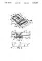
- FIG. 5is a cross-sectional view taken through the connector holder along line V--V in FIG. 3 and showing a part of the holder on a larger scale;
- FIG. 6is a rear end view of the holder taken in the direction of arrow VI--VI in FIG. 3;
- FIG. 7is an isometric view of a connector holder assembly incorporating connector holders as shown in FIGS. 2 to 6;
- FIGS. 8 and 9are isometric views from opposite sides of a rigid member forming part of the assembly of FIG. 7;
- FIG. 10is a cross-sectional view taken through the assembly along line X--X in FIG. 7 and showing a detail of the assembly;
- FIG. 11is an isometric view of the assembly of FIG. 7 and showing the connector holders of the assembly being assembled into the distribution frame shown in FIG. 1;
- FIG. 12is a diagrammatic view of the distribution frame together with its connector holders showing optical connections from the frame and within a building.
- an optical fiber distribution frame 10holds two vertical banks 12 of planar connector holders 14 for connecting a plurality of incoming optical fibers to outgoing optical fibers.
- the distribution framecomprises a rear wall 16 and remote side walls 18 which extend from the rear to an open front of the frame. Between the side walls 18 are two other walls 20 which extend forwardly from the rear wall 16 and lie in parallel relationship to the side walls 18.
- a side wall 18 and its corresponding wall 20define between them receiving stations for the connector holders 14.
- the two walls 20are spaced apart as shown in FIG. 2 to provide a storage channel 22 for optical fibers leading from front end regions of the connectors as will be described.
- Each of the connector holders 14is insertable into a respective receiving station from the front of the distribution frame and is locatable in two positions in the respective station, i.e. in a rearward operative position as shown in FIG. 2 and in full outline in FIG. 1, and a forward connector access position as shown in chain-dotted outline in FIG. 1.
- the arrangement of the holders 14 in the distribution frame and the construction of the distribution frameis basically similar to that described in copending U.S. patent application Ser. No. 423,281 filed Oct. 18, 1989 now U.S. Pat. No. 5,071,211 (Canadian Application Serial No. 615,192 filed Sep. 29, 1989), entitled "Connector Holders and Distribution Frame and Connector Holder Assemblies for Optical Cable" in the name of G. Debortoli, et al.
- Each of the connector holders 14is basically of the structure described in the above-mentioned copending application. Holders in the right-hand bank 12 in FIG. 1 are of opposite hand to those in the left-hand bank 12. In the following description, a holder for accommodation in the right-hand bank will be described with the understanding that the holders in the left-hand bank are of opposite hand.
- Each holder 14 of the right-hand bankis of planar configuration as shown in FIG. 3 and has a planar base 24 (FIGS. 3, 4 and 5) in the plane of the holder, the base 24 being bordered by side walls 26 which extend to both sides of the base in the depth direction of the holder.
- a mounting region 28 for optical connectors 30At a front end region of the holder is provided a mounting region 28 for optical connectors 30 to be positioned laterally spaced from one another across the width of the holder frame from one side wall 26 to the other.
- a storage compartment 31On one side of the base and between the side walls 26 there is provided a storage compartment 31 (FIGS.
- the storage compartment 31extends between the mounting region 28 and a rear end wall 34 at a rear end region of the holder, the rear end wall extending between the side walls 26.
- the compartment 31is provided with a cover 36 which covers substantially the whole of the compartment 31 except the surrounding edges.
- the cover 36is movable at right angles to its plane between an inner operative position as shown in FIG.
- the coveris mounted upon a central structure shown at 38 in FIG. 4 and is locatable in its operative and retracted positions by latches 40.
- Localized flanges 42extend inwardly into recesses in the cover 36 so as to distort the gap around the cover to render it impossible for a tube to be removed with the cover in its operative position.
- a second compartment 44is provided on the other side of the holder as shown in FIG. 3 . This compartment also extends from the mounting region to the rear end 34 of the holder.
- each connector 30is held by a connector mount 49 which is provided with a forwardly facing foot 50 (FIG. 5) which is to be disposed under an overhanging element 52 at a front side of the recess.
- the other end of each connector mounthas a flexible latch 54 which is received through a hole 56 in the base of the recess, the latch then engaging beneath the inclined side 46 to hold the connector mounts in position.
- a plurality of ribs 57which are laterally spaced apart across the width of the holder and extend in a direction from the front end region towards the rear end region.
- the two compartmentsare connected at the rear wall 34 of the connector by interconnecting passage 62 (see FIG. 6) to enable the tube 32 to pass from one compartment to the other.
- a splice block 64(FIG. 3) is provided for connecting incoming optical fibers to pigtail fibers, the other ends of the pigtail fibers being provided by the connectors 30.
- Each holder 14also comprises a connector guard 66 mounted at its front end.
- the guardis as described in the copending application referred to above in that the guard 66 has two sides 68 and 70 and a front 72 which extends across the width of the holder.
- the two sides 68 and 70are hinged so as to be movable between an upper connector guarding position in the plane of the holder as shown in FIG. 3 and a downward position (not shown) removed from the guarding position.
- the guard 66 and the mounting for the guarddiffer however from the previous application in the following ways.
- the guardis pivoted in front of the mounting region 28 upon two forward extensions 74 of the side walls 26 at positions 76 and is normally retained in the guarding position by domed protrusions 78 on free ends of the arms 74, the domed protrusions extending into holes in the side walls 68 and 70.
- a space defined between the mounting region 28 and the front 72 of the guardhas an inlet provided between the front 72 and an arcuate extension 80 of the side wall 70.
- the arcuate extension 80extends laterally sideways from the side 70 and the holder and provides a means for limiting the minimum bend radius of fibers extending from the space while allowing them to pass rearwardly of the holder.
- the arcuate extension 80is spaced slightly rearwardly of the front 72 of the guard to provide the inlet.
- Means for limiting the minimum bend radius of optical fibers in the spaceis provided for ends of fibers as they extend from forward facing ends of the connectors 30 when they change direction to pass through the inlet.
- the means for limiting the minimum bend radius at this positioncomprises a plurality of arcuate vanes 82 (FIG. 3) which are disposed in spaced positions across the width of the holder and are supported each by one end upon a flange 84 extending rearwardly from the front 72.
- the vanes 82extend upwardly from flange 84 and are suitably positioned relative to respective mounting positions for the connectors 30 so that ends of optical fibers in the space and extending to the connectors 30 engage against a convex surface of a respective vane as it changes direction towards the inlet.
- a connector holder assembly 86for simplifying the assembly of connector holders into the distribution frame will now be described.
- This assemblyprovides connector holders 14 for the right-hand bank 12 of holders.
- the assembly 86comprises a plurality, namely four, holders 14 disposed in a vertical stack. It should be understood that while four holders are described in the assembly 86, any number of stacked holders may be incorporated dependent upon their handleability.
- Each of the holders 86has been previously fitted, before incorporation into the stack, with a plurality of connectors 30 (FIGS. 3 and 5) in their side-by-side positions in the mounting region 28. Also, each holder has been previously provided with its own optical fiber storage tube 32 with its outwardly extending length 37, the tube extending through the inlet 35 (FIG. 4) and extending in coiled form around the compartment 31. The tube passes from the storage compartment 31 through the interconnecting passage 62 (FIG. 6) and into the storage compartment 44, the tube having an end which is held to the holder at position 87 by a strain relief.
- a plurality of fibers 88(FIG. 2), one for each connector, extend from the tube end and coil around the compartment 44 before being spliced at the splice block 64 to pigtail fibers 90 which form pigtails with the connectors 30 to which they are optically connected.
- each of the tubes 32forms part of an optical cable 94 (FIG. 7) with all of the cable terminating except for the tubes 32 so that the projecting outwardly extending lengths 37 and the parts of tubes 32 within the holders are provided for connection to the connectors 30.
- the holders 14 of the assembly 86are held in their stacked positions by a positioning and retaining means detachably connected to the stack.
- This position and retaining meanscomprises two rigid members 96 disposed one on each side of the stack.
- Each member as shown in FIGS. 8, 9 and 10comprises an elongate stack engaging portion 98 which is disposed vertically of the stack with the members 96 disposed directly outwardly of the mounting region 28.
- Each holder 14 in the stackhas, on its underside, two recesses 100, one recess for each holder only being shown in FIG. 10.
- the recesses for each holderare disposed one at each end of the mounting region 28 and are spaced from the side surface 102 of the holder.
- the lowermost holder 14 of the stackhas its recesses 100 facing outwardly, i.e. downwardly from the stack.
- Each rigid member 96has a lower end which turns around and upwardly as a lipped flange 104 (FIGS. 8 and 10). With each rigid member in a stack supporting position (FIG. 7) i.e. one on each side of the stack, the lower end of the rigid member, i.e. the lipped flange 104, extends around a respective side of the stack and the lipped flange engages and registers within the respective recess as shown by FIG. 10.
- the rigid membersare assembled onto the stack with each member initially inclined slightly outwards from the stack and with the lipped flange engaging within the respective recess 100.
- the rigid membersare then pivoted upwardly into engagement with the sides of the stack (FIGS. 7 and 10) and are held in this position by an urging means which pulls the upper ends of the rigid members towards each other and against the sides of the stack.
- This urging meanscomprises a flexible severable tie member 106 (FIG. 7) of known plastics structure which passes over the stack and through apertures 108 (FIGS. 8 and 9), at top ends of the stack engaging portions 98, to provide a continuous band.
- the rigid members 96locate the holders 14 in vertical alignment in the stack and at specific relative positions vertically. Vertical alignment and positioning is provided by interengaging ribs and rib engaging grooves which may be provided alternatively upon the holders or upon the rigid members 96. In this embodiment, however, on the holders short vertical ribs 110 (FIGS. 3 and 4) extend outwards from the sides of each holder. The ribs 110 at each side are received within a vertical groove 110 (FIG. 8) which extends vertically from end-to-end of a respective stack engaging portion 98 and the holders are thus vertically aligned.
- each holder 14has on each side wall 26 an outward horizontal flange 114 which extends from and joins the respective rib 110 to the rear end of the holder.
- the ribs 114 of each holderare slidable upon horizontal support surfaces of supporting track guides (not shown) which are carried in fixed positions upon the walls 18 and 20 of the distribution frame and extend from front to rear of the frame.
- supporting track guidesnot shown
- each holderis movable into and out of its respective receiving station by horizontal sliding movement through the front of the frame.
- the horizontal support surfacesare vertically spaced just sufficiently to provide slight vertical clearance between holders 14 to allow for their horizontal movement within the frame without interfering with one another.
- the ribs 114are received in the assembly 86 within short horizontal grooves 116 of the respective stack engaging portions 98 (FIGS. 8 and 9), the grooves 116 interconnecting with the vertical groove 112.
- the grooves 116are spaced apart so that the holders 114 at their front end regions are vertically located in the slightly spaced positions they will assume when in the frame.
- the rigid member 96which is disposed at the side of the stack of holders from which the tube length 37 extends, is provided with a tapered flange 118 extending normal to the plane of the stack engaging portion 98 and in a direction away from the grooves 112, 116.
- This flangecarries at its outer end, an integral channel 120 of V-shaped section which extends away from the stack engaging portion 98 and in planes substantially parallel to those of the stack engaging portion.
- the end of the jacket of the cable 94is held securely within the channel 120 (FIG. 7) by ties 122 which pass around the jacket and through apertures in the channel for location purposes.
- a plurality of the assemblies 86are pre-built under factory conditions for installation within a distribution frame.
- the holders 14 within each of the assemblies 88are assembled together each with its pigtail fibers 90 extending from the connector 30 to the splice block 68 of the holder.
- the cable 94 for each assemblyhas its optical fiber tubes 32 extending from its end, these tubes extending into each of the four respective holders 14 and passing around the storage compartments 31 and 44 in the manner described above.
- the four holders 14 for the assemblyare then stacked together under factory conditions and the rigid members 96 are then disposed in their positions at the sides of the stack, as described above with regard to FIGS. 7 and 10, prior to the flexible severable member 106 being placed in position to hold the assembly together.
- the cable sheathis then secured to the V-shaped channel 120 by the ties 122 as described.
- a plurality of the assemblies 86are then offered to the right-hand bank 12 of receiving stations in the distribution frame.
- the rear ends of the holdersextend rearwardly beyond the rigid members 96 and are thus locatable substantially in their respective receiving stations in the distribution frame before the retaining and positioning means need be removed.
- previous holders 14are already disposed in their receiving stations within the right-hand bank of the distribution frame and the outwardly extending ends 37 of the tubes extend into their cables 94 which are stored in a vertical storage channel 124 of the distribution frame. All of these holders have been inserted from assemblies such as 86 discussed above.
- the next assembly 86is then inserted into the frame as shown by FIG.
- the flexible tie member 106is severed. This causes the rigid members 96 to pivot outwardly under their own weight away from the stack of members 14 as shown by FIG. 11 so that the rigid members may be removed. This operation is preceded by severing the ties 122 which hold the cable to the grooved member 120.
- the holders 14 of this subassemblyare then moved backwards into their receiving stations so as to lie with the fronts 72 of their guards 66 vertically aligned with the previous holders.
- the corresponding cable 94is then positioned by the side of the previous cable inside the storage channel 124.
- the right-hand bank of the receiving stations in the distribution frameare equipped with holders in the manner described above.
- the left-hand bank 12 of receiving stations(FIG. 1) is dealt with in similar manner with holders of opposite hand from those discussed in the embodiment.
- patch cords 126are connected from selected connectors 30 in any holder 14 in the right-hand bank 12 to any selected connector 30 in any holder 14 in the left-hand bank 12. These patch cords as shown in FIG. 2 hang down in loops between the banks of holders within the vertical storage channel 22 provided as shown in FIGS. 1 and 2.
- the cables 94are of sufficient length to extend to a splice closure 128 for splicing to an incoming cable 130 entering into the building.
- Optical fibers within tubes of the incoming cable 130diverge within the splice closure to be spliced to individual fibers of the tubes 94.
- FIG. 12shows two tubes, by way of example, extending from the distribution frame 10 to the splice closure 128.
- the patch cords 126then extend between the two banks of holders and the cables 94 from the left-hand bank as shown in FIG. 12 extend into an equipment bay 132 in which the optical fibers of that cable are connected to further optical fibers which extend interiorly throughout the building to individual items of telecommunications equipment.
- the total on-site assembly time for the holders into the distribution frame and connection through from an incoming cable to various telecommunications equipmentis significantly shortened using the assemblies 86 of optical connectors according to the embodiment.
Landscapes
- Physics & Mathematics (AREA)
- General Physics & Mathematics (AREA)
- Optics & Photonics (AREA)
- Light Guides In General And Applications Therefor (AREA)
Abstract
Description
Claims (11)
Priority Applications (1)
| Application Number | Priority Date | Filing Date | Title |
|---|---|---|---|
| US07/611,228US5138688A (en) | 1990-11-09 | 1990-11-09 | Optical connector holder assembly |
Applications Claiming Priority (1)
| Application Number | Priority Date | Filing Date | Title |
|---|---|---|---|
| US07/611,228US5138688A (en) | 1990-11-09 | 1990-11-09 | Optical connector holder assembly |
Publications (1)
| Publication Number | Publication Date |
|---|---|
| US5138688Atrue US5138688A (en) | 1992-08-11 |
Family
ID=24448157
Family Applications (1)
| Application Number | Title | Priority Date | Filing Date |
|---|---|---|---|
| US07/611,228Expired - LifetimeUS5138688A (en) | 1990-11-09 | 1990-11-09 | Optical connector holder assembly |
Country Status (1)
| Country | Link |
|---|---|
| US (1) | US5138688A (en) |
Cited By (112)
| Publication number | Priority date | Publication date | Assignee | Title |
|---|---|---|---|---|
| US5187766A (en)* | 1991-02-27 | 1993-02-16 | Siemens Aktiengesellschaft | Optical fiber waveguide division rack for holding plural cassettes |
| US5297229A (en)* | 1992-03-26 | 1994-03-22 | Fujitsu Limited | System for extending communication equipment using flat coaxial cable |
| US5337400A (en)* | 1992-10-28 | 1994-08-09 | Northern Telecom Limited | Distribution frame and optical connector holder combination |
| US5353367A (en)* | 1993-11-29 | 1994-10-04 | Northern Telecom Limited | Distribution frame and optical connector holder combination |
| US5363466A (en)* | 1992-02-21 | 1994-11-08 | Mars Actel | Assembly of hinged flat modules |
| US5402515A (en)* | 1994-03-01 | 1995-03-28 | Minnesota Mining And Manufacturing Company | Fiber distribution frame system, cabinets, trays and fiber optic connector couplings |
| US5412497A (en)* | 1992-02-24 | 1995-05-02 | Fujitsu Limited | Optical communication device with optical modules and optical fiber supporting plates |
| US5448675A (en)* | 1994-06-09 | 1995-09-05 | At&T Ipm Corp. | Telecommunications distribution frame with tracing |
| GB2287796A (en)* | 1994-03-24 | 1995-09-27 | Augat Limited | Tubular optical fibre guide for splice tray |
| US5511144A (en)* | 1994-06-13 | 1996-04-23 | Siecor Corporation | Optical distribution frame |
| US5530954A (en)* | 1995-01-13 | 1996-06-25 | Telect, Inc. | Telecommunication fiber optic patch panel shelf assembly |
| US5550947A (en)* | 1994-06-20 | 1996-08-27 | Pirelli General Plc | Slidable optical fiber interconnecting tray with flexible fiber guiding tubes |
| US5638481A (en)* | 1995-09-26 | 1997-06-10 | Lucent Technologies Inc. | Flush mounted outlet |
| US5717812A (en)* | 1995-09-06 | 1998-02-10 | The Whitaker Corporation | Holder for fiber optic splice connectors |
| US5724467A (en)* | 1995-10-11 | 1998-03-03 | The Whitaker Corporation | Adapter to secure fiber optic connectors within a telecommuniations box |
| US5812727A (en)* | 1996-01-31 | 1998-09-22 | Asahi Kogaku Kogyo Kabushiki Kaisha | Holder for optical fibers in a scanning optical device |
| US5913006A (en)* | 1997-11-25 | 1999-06-15 | Northern Telecom Limited | Fibre slack storage retractable panel and interface |
| US6362422B1 (en) | 2000-06-02 | 2002-03-26 | Michael T. Vavrik | Enclosure for use in fiber optic management systems |
| US6501899B1 (en) | 2000-06-02 | 2002-12-31 | Panduit Corp. | Vertical cable management system |
| US6584267B1 (en) | 2000-06-02 | 2003-06-24 | Panduit Corp. | Cable management system |
| US6614978B1 (en) | 2000-06-02 | 2003-09-02 | Panduit Corp. | Slack cable management system |
| US6647197B1 (en) | 2000-06-02 | 2003-11-11 | Panduit Corp. | Modular latch and guide rail arrangement for use in fiber optic cable management systems |
| US6654536B2 (en)* | 2001-04-12 | 2003-11-25 | Corning Cable Systems Llc | Fiber management frame having connector platform |
| WO2006053603A1 (en)* | 2004-11-11 | 2006-05-26 | Ccs Technology, Inc. | Fibre optic distribution unit |
| US20060247386A1 (en)* | 2005-04-29 | 2006-11-02 | Chevron Oronite Company Llc. | Lubricating oil additive composition and method of making the same |
| US20070027267A1 (en)* | 2005-04-29 | 2007-02-01 | Chevron Oronite Company Llc | Lubricating oil additive composition and method of making the same |
| EP1916293A1 (en) | 2006-10-27 | 2008-04-30 | Chevron Oronite Company LLC | A lubricating oil additive composition and method of making the same |
| US20080103076A1 (en)* | 2006-10-27 | 2008-05-01 | Chevron Oronite Company Llc | Lubricating oil additive composition and method of making the same |
| US7618928B2 (en) | 2005-08-31 | 2009-11-17 | Chevron Oronite Company Llc | Lubricating oil additive composition and method of making the same |
| US20100054683A1 (en)* | 2008-08-29 | 2010-03-04 | Cooke Terry L | Rear-Installable Fiber Optic Modules and Equipment |
| US20100054682A1 (en)* | 2008-08-29 | 2010-03-04 | Cooke Terry L | Independently Translatable Modules and Fiber Optic Equipment Trays in Fiber Optic Equipment |
| US20100215330A1 (en)* | 2009-02-24 | 2010-08-26 | Bartlomiej Sokolowski | Holding Device for a Cable or an Assembly for Use With a Cable |
| US20100296790A1 (en)* | 2009-05-21 | 2010-11-25 | Cooke Terry L | Fiber Optic Equipment Supporting Moveable Fiber Optic Equipment Tray(s) and Module(s), and Related Equipment and Methods |
| US20100322583A1 (en)* | 2009-06-19 | 2010-12-23 | Cooke Terry L | High Density and Bandwidth Fiber Optic Apparatuses and Related Equipment and Methods |
| US20100322582A1 (en)* | 2009-06-19 | 2010-12-23 | Cooke Terry L | High Capacity Fiber Optic Connection Infrastructure Apparatus |
| US20100322581A1 (en)* | 2009-06-19 | 2010-12-23 | Cooke Terry L | High Fiber Optic Cable Packing Density Apparatus |
| US20100322579A1 (en)* | 2009-06-19 | 2010-12-23 | Cooke Terry L | High-density fiber optic modules and module housings and related equipment |
| US20110150407A1 (en)* | 2009-12-18 | 2011-06-23 | Beamon Hubert B | Rotary Locking Apparatus for Fiber Optic Equipment Trays and Related Methods |
| EP2383595A1 (en)* | 2010-04-30 | 2011-11-02 | Corning Cable Systems LLC | Fiber optic module with adapter side entry opening |
| US20130004125A1 (en)* | 2009-12-23 | 2013-01-03 | Prysmian S.p. A. | Optical termination assembly |
| US8385711B2 (en) | 2010-04-30 | 2013-02-26 | Corning Cable Systems Llc | Multi-configurable splice holder |
| US8417074B2 (en) | 2008-11-21 | 2013-04-09 | Adc Telecommunications, Inc. | Fiber optic telecommunications module |
| US8542973B2 (en) | 2010-04-23 | 2013-09-24 | Ccs Technology, Inc. | Fiber optic distribution device |
| US8593828B2 (en) | 2010-02-04 | 2013-11-26 | Corning Cable Systems Llc | Communications equipment housings, assemblies, and related alignment features and methods |
| US8660397B2 (en) | 2010-04-30 | 2014-02-25 | Corning Cable Systems Llc | Multi-layer module |
| US8662760B2 (en) | 2010-10-29 | 2014-03-04 | Corning Cable Systems Llc | Fiber optic connector employing optical fiber guide member |
| US8699838B2 (en) | 2009-05-14 | 2014-04-15 | Ccs Technology, Inc. | Fiber optic furcation module |
| US8705926B2 (en) | 2010-04-30 | 2014-04-22 | Corning Optical Communications LLC | Fiber optic housings having a removable top, and related components and methods |
| US8718436B2 (en) | 2010-08-30 | 2014-05-06 | Corning Cable Systems Llc | Methods, apparatuses for providing secure fiber optic connections |
| US8770861B2 (en) | 2011-09-27 | 2014-07-08 | Tyco Electronics Corporation | Outside plant termination enclosure |
| US8879881B2 (en) | 2010-04-30 | 2014-11-04 | Corning Cable Systems Llc | Rotatable routing guide and assembly |
| US8913866B2 (en) | 2010-03-26 | 2014-12-16 | Corning Cable Systems Llc | Movable adapter panel |
| US8953924B2 (en) | 2011-09-02 | 2015-02-10 | Corning Cable Systems Llc | Removable strain relief brackets for securing fiber optic cables and/or optical fibers to fiber optic equipment, and related assemblies and methods |
| US8958679B2 (en) | 2010-03-02 | 2015-02-17 | Tyco Electronics Services Gmbh | Fibre-optic telecommunications module |
| US8989547B2 (en) | 2011-06-30 | 2015-03-24 | Corning Cable Systems Llc | Fiber optic equipment assemblies employing non-U-width-sized housings and related methods |
| US8985862B2 (en) | 2013-02-28 | 2015-03-24 | Corning Cable Systems Llc | High-density multi-fiber adapter housings |
| US8995812B2 (en) | 2012-10-26 | 2015-03-31 | Ccs Technology, Inc. | Fiber optic management unit and fiber optic distribution device |
| US9002166B2 (en) | 2011-10-07 | 2015-04-07 | Adc Telecommunications, Inc. | Slidable fiber optic connection module with cable slack management |
| US9008485B2 (en) | 2011-05-09 | 2015-04-14 | Corning Cable Systems Llc | Attachment mechanisms employed to attach a rear housing section to a fiber optic housing, and related assemblies and methods |
| US9014527B2 (en) | 2011-04-25 | 2015-04-21 | Adc Telecommunication, Inc. | Rack and chassis for fiber optic sliding adapter modules |
| US9022814B2 (en) | 2010-04-16 | 2015-05-05 | Ccs Technology, Inc. | Sealing and strain relief device for data cables |
| US9038832B2 (en) | 2011-11-30 | 2015-05-26 | Corning Cable Systems Llc | Adapter panel support assembly |
| US9057859B2 (en) | 2011-10-07 | 2015-06-16 | Adc Telecommunications, Inc. | Slidable fiber optic connection module with cable slack management |
| US9075203B2 (en) | 2012-01-17 | 2015-07-07 | Adc Telecommunications, Inc. | Fiber optic adapter block |
| US9075217B2 (en) | 2010-04-30 | 2015-07-07 | Corning Cable Systems Llc | Apparatuses and related components and methods for expanding capacity of fiber optic housings |
| US9075216B2 (en) | 2009-05-21 | 2015-07-07 | Corning Cable Systems Llc | Fiber optic housings configured to accommodate fiber optic modules/cassettes and fiber optic panels, and related components and methods |
| US9116324B2 (en) | 2010-10-29 | 2015-08-25 | Corning Cable Systems Llc | Stacked fiber optic modules and fiber optic equipment configured to support stacked fiber optic modules |
| US9128262B2 (en) | 2013-02-05 | 2015-09-08 | Adc Telecommunications, Inc. | Slidable telecommunications tray with cable slack management |
| US9146374B2 (en) | 2012-09-28 | 2015-09-29 | Adc Telecommunications, Inc. | Rapid deployment packaging for optical fiber |
| US9170391B2 (en) | 2011-10-07 | 2015-10-27 | Adc Telecommunications, Inc. | Slidable fiber optic connection module with cable slack management |
| US9195021B2 (en) | 2012-09-21 | 2015-11-24 | Adc Telecommunications, Inc. | Slidable fiber optic connection module with cable slack management |
| US9213161B2 (en) | 2010-11-05 | 2015-12-15 | Corning Cable Systems Llc | Fiber body holder and strain relief device |
| US9223094B2 (en) | 2012-10-05 | 2015-12-29 | Tyco Electronics Nederland Bv | Flexible optical circuit, cassettes, and methods |
| US9250409B2 (en) | 2012-07-02 | 2016-02-02 | Corning Cable Systems Llc | Fiber-optic-module trays and drawers for fiber-optic equipment |
| US9279951B2 (en) | 2010-10-27 | 2016-03-08 | Corning Cable Systems Llc | Fiber optic module for limited space applications having a partially sealed module sub-assembly |
| US9389384B2 (en) | 2013-02-27 | 2016-07-12 | Commscope Technologies Llc | Slidable fiber optic connection module with cable slack management |
| US9435975B2 (en) | 2013-03-15 | 2016-09-06 | Commscope Technologies Llc | Modular high density telecommunications frame and chassis system |
| US9494758B2 (en) | 2014-04-03 | 2016-11-15 | Commscope Technologies Llc | Fiber optic distribution system |
| US9519118B2 (en) | 2010-04-30 | 2016-12-13 | Corning Optical Communications LLC | Removable fiber management sections for fiber optic housings, and related components and methods |
| US9535229B2 (en) | 2011-10-07 | 2017-01-03 | Commscope Technologies Llc | Fiber optic cassette, system, and method |
| US9541726B2 (en) | 2013-04-24 | 2017-01-10 | Adc Czech Republic, S.R.O. | Optical fiber distribution system |
| US9568699B2 (en) | 2013-01-29 | 2017-02-14 | CommScope Connectivity Belgium BVBA | Optical fiber distribution system |
| US9632270B2 (en) | 2010-04-30 | 2017-04-25 | Corning Optical Communications LLC | Fiber optic housings configured for tool-less assembly, and related components and methods |
| US9645317B2 (en) | 2011-02-02 | 2017-05-09 | Corning Optical Communications LLC | Optical backplane extension modules, and related assemblies suitable for establishing optical connections to information processing modules disposed in equipment racks |
| US9720195B2 (en) | 2010-04-30 | 2017-08-01 | Corning Optical Communications LLC | Apparatuses and related components and methods for attachment and release of fiber optic housings to and from an equipment rack |
| US9851524B2 (en) | 2014-01-28 | 2017-12-26 | Commscope Technologies Llc | Slidable fiber optic connection module with cable slack management |
| US10082636B2 (en) | 2012-09-21 | 2018-09-25 | Commscope Technologies Llc | Slidable fiber optic connection module with cable slack management |
| US10247886B2 (en) | 2014-12-10 | 2019-04-02 | Commscope Technologies Llc | Fiber optic cable slack management module |
| US10261281B2 (en) | 2015-04-03 | 2019-04-16 | CommScope Connectivity Belgium BVBA | Telecommunications distribution elements |
| US10409020B2 (en) | 2013-04-24 | 2019-09-10 | CommScope Connectivity Belgium BVBA | Universal mounting mechanism for mounting a telecommunications chassis to a telecommunciations fixture |
| US10539757B2 (en) | 2016-04-19 | 2020-01-21 | Commscope, Inc. Of North Carolina | Telecommunications chassis with slidable trays |
| US11215767B2 (en) | 2017-06-07 | 2022-01-04 | Commscope Technologies Llc | Fiber optic adapter and cassette |
| US11256054B2 (en) | 2018-04-16 | 2022-02-22 | Commscope Technologies Llc | Adapter structure |
| US11294136B2 (en) | 2008-08-29 | 2022-04-05 | Corning Optical Communications LLC | High density and bandwidth fiber optic apparatuses and related equipment and methods |
| US11372165B2 (en) | 2011-09-12 | 2022-06-28 | Commscope Technologies Llc | Flexible lensed optical interconnect device for signal distribution |
| US11372186B2 (en) | 2017-04-04 | 2022-06-28 | Commscope Technologies Llc | Optical splice and termination module |
| US11385429B2 (en) | 2017-10-18 | 2022-07-12 | Commscope Technologies Llc | Fiber optic connection cassette |
| US11409068B2 (en) | 2017-10-02 | 2022-08-09 | Commscope Technologies Llc | Fiber optic circuit and preparation method |
| US11409067B2 (en) | 2018-08-31 | 2022-08-09 | CommScope Connectivity Belgium BVBA | Frame assemblies for optical fiber distribution elements |
| US11448831B2 (en) | 2018-08-31 | 2022-09-20 | CommScope Connectivity Belgium BVBA | Frame assemblies for optical fiber distribution elements |
| US11448844B2 (en) | 2018-08-31 | 2022-09-20 | CommScope Connectivity Belgium BVBA | Frame assemblies for optical fiber distribution elements |
| US11448845B2 (en) | 2018-08-31 | 2022-09-20 | CommScope Connectivity Belgium BVBA | Frame assemblies for optical fiber distribution elements |
| US11592628B2 (en) | 2012-09-28 | 2023-02-28 | Commscope Technologies Llc | Fiber optic cassette |
| US11635578B2 (en) | 2018-04-17 | 2023-04-25 | CommScope Connectivity Belgium BVBA | Telecommunications distribution elements |
| US11674345B2 (en) | 2016-04-19 | 2023-06-13 | Commscope, Inc. Of North Carolina | Door assembly for a telecommunications chassis with a combination hinge structure |
| US11852882B2 (en) | 2018-02-28 | 2023-12-26 | Commscope Technologies Llc | Packaging assembly for telecommunications equipment |
| US11947177B2 (en) | 2019-01-25 | 2024-04-02 | CommScope Connectivity Belgium BVBA | Frame assemblies for optical fiber distribution elements |
| US12007615B2 (en) | 2018-10-23 | 2024-06-11 | CommScope Connectivity Belgium BVBA | Frame assemblies for optical fiber distribution elements |
| US12050358B2 (en) | 2018-08-31 | 2024-07-30 | CommScope Connectivity Belgium BVBA | Frame assemblies for optical fiber distribution elements |
| US12099246B2 (en) | 2020-01-24 | 2024-09-24 | CommScope Connectivity Belgium BVBA | Telecommunications distribution elements |
| US12174443B2 (en) | 2020-01-22 | 2024-12-24 | CommScope Connectivity Belgium BVBA | Cable termination units for optical fiber distribution elements |
| US12339511B2 (en) | 2020-03-31 | 2025-06-24 | Commscope Technologies Llc | Fiber optic cable management systems and methods |
Citations (4)
| Publication number | Priority date | Publication date | Assignee | Title |
|---|---|---|---|---|
| EP0211208A1 (en)* | 1985-07-30 | 1987-02-25 | Siemens Aktiengesellschaft | Distributor for fibre-optic conductors |
| DE3532314A1 (en)* | 1985-09-11 | 1987-03-12 | Philips Patentverwaltung | RECEIVING DEVICE FOR A STOCK LENGTH OF AN OPTICAL PIPE |
| EP0281196A2 (en)* | 1987-03-03 | 1988-09-07 | Philips Patentverwaltung GmbH | Storing device for the supply length of at least one light wave guide |
| US4995688A (en)* | 1989-07-31 | 1991-02-26 | Adc Telecommunications, Inc. | Optical fiber distribution frame |
- 1990
- 1990-11-09USUS07/611,228patent/US5138688A/ennot_activeExpired - Lifetime
Patent Citations (4)
| Publication number | Priority date | Publication date | Assignee | Title |
|---|---|---|---|---|
| EP0211208A1 (en)* | 1985-07-30 | 1987-02-25 | Siemens Aktiengesellschaft | Distributor for fibre-optic conductors |
| DE3532314A1 (en)* | 1985-09-11 | 1987-03-12 | Philips Patentverwaltung | RECEIVING DEVICE FOR A STOCK LENGTH OF AN OPTICAL PIPE |
| EP0281196A2 (en)* | 1987-03-03 | 1988-09-07 | Philips Patentverwaltung GmbH | Storing device for the supply length of at least one light wave guide |
| US4995688A (en)* | 1989-07-31 | 1991-02-26 | Adc Telecommunications, Inc. | Optical fiber distribution frame |
Cited By (230)
| Publication number | Priority date | Publication date | Assignee | Title |
|---|---|---|---|---|
| US5187766A (en)* | 1991-02-27 | 1993-02-16 | Siemens Aktiengesellschaft | Optical fiber waveguide division rack for holding plural cassettes |
| US5363466A (en)* | 1992-02-21 | 1994-11-08 | Mars Actel | Assembly of hinged flat modules |
| US5412497A (en)* | 1992-02-24 | 1995-05-02 | Fujitsu Limited | Optical communication device with optical modules and optical fiber supporting plates |
| US5297229A (en)* | 1992-03-26 | 1994-03-22 | Fujitsu Limited | System for extending communication equipment using flat coaxial cable |
| US5337400A (en)* | 1992-10-28 | 1994-08-09 | Northern Telecom Limited | Distribution frame and optical connector holder combination |
| US5353367A (en)* | 1993-11-29 | 1994-10-04 | Northern Telecom Limited | Distribution frame and optical connector holder combination |
| US5402515A (en)* | 1994-03-01 | 1995-03-28 | Minnesota Mining And Manufacturing Company | Fiber distribution frame system, cabinets, trays and fiber optic connector couplings |
| GB2287796A (en)* | 1994-03-24 | 1995-09-27 | Augat Limited | Tubular optical fibre guide for splice tray |
| US5448675A (en)* | 1994-06-09 | 1995-09-05 | At&T Ipm Corp. | Telecommunications distribution frame with tracing |
| US5511144A (en)* | 1994-06-13 | 1996-04-23 | Siecor Corporation | Optical distribution frame |
| US5550947A (en)* | 1994-06-20 | 1996-08-27 | Pirelli General Plc | Slidable optical fiber interconnecting tray with flexible fiber guiding tubes |
| US5530954A (en)* | 1995-01-13 | 1996-06-25 | Telect, Inc. | Telecommunication fiber optic patch panel shelf assembly |
| US5717812A (en)* | 1995-09-06 | 1998-02-10 | The Whitaker Corporation | Holder for fiber optic splice connectors |
| US5638481A (en)* | 1995-09-26 | 1997-06-10 | Lucent Technologies Inc. | Flush mounted outlet |
| US5724467A (en)* | 1995-10-11 | 1998-03-03 | The Whitaker Corporation | Adapter to secure fiber optic connectors within a telecommuniations box |
| US5812727A (en)* | 1996-01-31 | 1998-09-22 | Asahi Kogaku Kogyo Kabushiki Kaisha | Holder for optical fibers in a scanning optical device |
| US5913006A (en)* | 1997-11-25 | 1999-06-15 | Northern Telecom Limited | Fibre slack storage retractable panel and interface |
| US6362422B1 (en) | 2000-06-02 | 2002-03-26 | Michael T. Vavrik | Enclosure for use in fiber optic management systems |
| US6501899B1 (en) | 2000-06-02 | 2002-12-31 | Panduit Corp. | Vertical cable management system |
| US6584267B1 (en) | 2000-06-02 | 2003-06-24 | Panduit Corp. | Cable management system |
| US6614978B1 (en) | 2000-06-02 | 2003-09-02 | Panduit Corp. | Slack cable management system |
| US6647197B1 (en) | 2000-06-02 | 2003-11-11 | Panduit Corp. | Modular latch and guide rail arrangement for use in fiber optic cable management systems |
| US6654536B2 (en)* | 2001-04-12 | 2003-11-25 | Corning Cable Systems Llc | Fiber management frame having connector platform |
| WO2006053603A1 (en)* | 2004-11-11 | 2006-05-26 | Ccs Technology, Inc. | Fibre optic distribution unit |
| US20060247386A1 (en)* | 2005-04-29 | 2006-11-02 | Chevron Oronite Company Llc. | Lubricating oil additive composition and method of making the same |
| US20070027267A1 (en)* | 2005-04-29 | 2007-02-01 | Chevron Oronite Company Llc | Lubricating oil additive composition and method of making the same |
| US7745541B2 (en) | 2005-04-29 | 2010-06-29 | Chevron Oronite Company Llc | Lubricating oil additive composition and method of making the same |
| US7745542B2 (en) | 2005-04-29 | 2010-06-29 | Chevron Oronite Company Llc | Lubricating oil additive composition and method of making the same |
| US7618928B2 (en) | 2005-08-31 | 2009-11-17 | Chevron Oronite Company Llc | Lubricating oil additive composition and method of making the same |
| EP1916293A1 (en) | 2006-10-27 | 2008-04-30 | Chevron Oronite Company LLC | A lubricating oil additive composition and method of making the same |
| US20080103076A1 (en)* | 2006-10-27 | 2008-05-01 | Chevron Oronite Company Llc | Lubricating oil additive composition and method of making the same |
| US11294136B2 (en) | 2008-08-29 | 2022-04-05 | Corning Optical Communications LLC | High density and bandwidth fiber optic apparatuses and related equipment and methods |
| US10444456B2 (en) | 2008-08-29 | 2019-10-15 | Corning Optical Communications LLC | High density and bandwidth fiber optic apparatuses and related equipment and methods |
| US11754796B2 (en) | 2008-08-29 | 2023-09-12 | Corning Optical Communications LLC | Independently translatable modules and fiber optic equipment trays in fiber optic equipment |
| US10606014B2 (en) | 2008-08-29 | 2020-03-31 | Corning Optical Communications LLC | Independently translatable modules and fiber optic equipment trays in fiber optic equipment |
| US11086089B2 (en) | 2008-08-29 | 2021-08-10 | Corning Optical Communications LLC | High density and bandwidth fiber optic apparatuses and related equipment and methods |
| US11092767B2 (en) | 2008-08-29 | 2021-08-17 | Corning Optical Communications LLC | High density and bandwidth fiber optic apparatuses and related equipment and methods |
| US20100054683A1 (en)* | 2008-08-29 | 2010-03-04 | Cooke Terry L | Rear-Installable Fiber Optic Modules and Equipment |
| US10126514B2 (en) | 2008-08-29 | 2018-11-13 | Corning Optical Communications, Llc | Independently translatable modules and fiber optic equipment trays in fiber optic equipment |
| US11294135B2 (en) | 2008-08-29 | 2022-04-05 | Corning Optical Communications LLC | High density and bandwidth fiber optic apparatuses and related equipment and methods |
| US10564378B2 (en) | 2008-08-29 | 2020-02-18 | Corning Optical Communications LLC | High density and bandwidth fiber optic apparatuses and related equipment and methods |
| US9910236B2 (en) | 2008-08-29 | 2018-03-06 | Corning Optical Communications LLC | High density and bandwidth fiber optic apparatuses and related equipment and methods |
| US10459184B2 (en) | 2008-08-29 | 2019-10-29 | Corning Optical Communications LLC | High density and bandwidth fiber optic apparatuses and related equipment and methods |
| US8184938B2 (en) | 2008-08-29 | 2012-05-22 | Corning Cable Systems Llc | Rear-installable fiber optic modules and equipment |
| US12072545B2 (en) | 2008-08-29 | 2024-08-27 | Corning Optical Communications LLC | High density and bandwidth fiber optic apparatuses and related equipment and methods |
| US11609396B2 (en) | 2008-08-29 | 2023-03-21 | Corning Optical Communications LLC | High density and bandwidth fiber optic apparatuses and related equipment and methods |
| US10422971B2 (en) | 2008-08-29 | 2019-09-24 | Corning Optical Communicatinos LLC | High density and bandwidth fiber optic apparatuses and related equipment and methods |
| US10120153B2 (en) | 2008-08-29 | 2018-11-06 | Corning Optical Communications, Llc | Independently translatable modules and fiber optic equipment trays in fiber optic equipment |
| US10416405B2 (en) | 2008-08-29 | 2019-09-17 | Corning Optical Communications LLC | Independently translatable modules and fiber optic equipment trays in fiber optic equipment |
| US8452148B2 (en) | 2008-08-29 | 2013-05-28 | Corning Cable Systems Llc | Independently translatable modules and fiber optic equipment trays in fiber optic equipment |
| US10852499B2 (en) | 2008-08-29 | 2020-12-01 | Corning Optical Communications LLC | High density and bandwidth fiber optic apparatuses and related equipment and methods |
| US20100054682A1 (en)* | 2008-08-29 | 2010-03-04 | Cooke Terry L | Independently Translatable Modules and Fiber Optic Equipment Trays in Fiber Optic Equipment |
| US9020320B2 (en) | 2008-08-29 | 2015-04-28 | Corning Cable Systems Llc | High density and bandwidth fiber optic apparatuses and related equipment and methods |
| US10094996B2 (en) | 2008-08-29 | 2018-10-09 | Corning Optical Communications, Llc | Independently translatable modules and fiber optic equipment trays in fiber optic equipment |
| US10222570B2 (en) | 2008-08-29 | 2019-03-05 | Corning Optical Communications LLC | Independently translatable modules and fiber optic equipment trays in fiber optic equipment |
| US8417074B2 (en) | 2008-11-21 | 2013-04-09 | Adc Telecommunications, Inc. | Fiber optic telecommunications module |
| US9059578B2 (en) | 2009-02-24 | 2015-06-16 | Ccs Technology, Inc. | Holding device for a cable or an assembly for use with a cable |
| US20100215330A1 (en)* | 2009-02-24 | 2010-08-26 | Bartlomiej Sokolowski | Holding Device for a Cable or an Assembly for Use With a Cable |
| US8699838B2 (en) | 2009-05-14 | 2014-04-15 | Ccs Technology, Inc. | Fiber optic furcation module |
| US8538226B2 (en) | 2009-05-21 | 2013-09-17 | Corning Cable Systems Llc | Fiber optic equipment guides and rails configured with stopping position(s), and related equipment and methods |
| US9075216B2 (en) | 2009-05-21 | 2015-07-07 | Corning Cable Systems Llc | Fiber optic housings configured to accommodate fiber optic modules/cassettes and fiber optic panels, and related components and methods |
| US20100296790A1 (en)* | 2009-05-21 | 2010-11-25 | Cooke Terry L | Fiber Optic Equipment Supporting Moveable Fiber Optic Equipment Tray(s) and Module(s), and Related Equipment and Methods |
| US8280216B2 (en) | 2009-05-21 | 2012-10-02 | Corning Cable Systems Llc | Fiber optic equipment supporting moveable fiber optic equipment tray(s) and module(s), and related equipment and methods |
| US20100322581A1 (en)* | 2009-06-19 | 2010-12-23 | Cooke Terry L | High Fiber Optic Cable Packing Density Apparatus |
| US20100322582A1 (en)* | 2009-06-19 | 2010-12-23 | Cooke Terry L | High Capacity Fiber Optic Connection Infrastructure Apparatus |
| US8712206B2 (en) | 2009-06-19 | 2014-04-29 | Corning Cable Systems Llc | High-density fiber optic modules and module housings and related equipment |
| US20100322583A1 (en)* | 2009-06-19 | 2010-12-23 | Cooke Terry L | High Density and Bandwidth Fiber Optic Apparatuses and Related Equipment and Methods |
| US20100322579A1 (en)* | 2009-06-19 | 2010-12-23 | Cooke Terry L | High-density fiber optic modules and module housings and related equipment |
| US8433171B2 (en) | 2009-06-19 | 2013-04-30 | Corning Cable Systems Llc | High fiber optic cable packing density apparatus |
| US8625950B2 (en) | 2009-12-18 | 2014-01-07 | Corning Cable Systems Llc | Rotary locking apparatus for fiber optic equipment trays and related methods |
| US20110150407A1 (en)* | 2009-12-18 | 2011-06-23 | Beamon Hubert B | Rotary Locking Apparatus for Fiber Optic Equipment Trays and Related Methods |
| US20130004125A1 (en)* | 2009-12-23 | 2013-01-03 | Prysmian S.p. A. | Optical termination assembly |
| US9383535B2 (en)* | 2009-12-23 | 2016-07-05 | Prysmian S.P.A. | Optical termination assemblies |
| US8992099B2 (en) | 2010-02-04 | 2015-03-31 | Corning Cable Systems Llc | Optical interface cards, assemblies, and related methods, suited for installation and use in antenna system equipment |
| US8593828B2 (en) | 2010-02-04 | 2013-11-26 | Corning Cable Systems Llc | Communications equipment housings, assemblies, and related alignment features and methods |
| US8958679B2 (en) | 2010-03-02 | 2015-02-17 | Tyco Electronics Services Gmbh | Fibre-optic telecommunications module |
| US8913866B2 (en) | 2010-03-26 | 2014-12-16 | Corning Cable Systems Llc | Movable adapter panel |
| US9022814B2 (en) | 2010-04-16 | 2015-05-05 | Ccs Technology, Inc. | Sealing and strain relief device for data cables |
| US8542973B2 (en) | 2010-04-23 | 2013-09-24 | Ccs Technology, Inc. | Fiber optic distribution device |
| US8385711B2 (en) | 2010-04-30 | 2013-02-26 | Corning Cable Systems Llc | Multi-configurable splice holder |
| US9075217B2 (en) | 2010-04-30 | 2015-07-07 | Corning Cable Systems Llc | Apparatuses and related components and methods for expanding capacity of fiber optic housings |
| US9519118B2 (en) | 2010-04-30 | 2016-12-13 | Corning Optical Communications LLC | Removable fiber management sections for fiber optic housings, and related components and methods |
| US9632270B2 (en) | 2010-04-30 | 2017-04-25 | Corning Optical Communications LLC | Fiber optic housings configured for tool-less assembly, and related components and methods |
| US8660397B2 (en) | 2010-04-30 | 2014-02-25 | Corning Cable Systems Llc | Multi-layer module |
| CN102236141B (en)* | 2010-04-30 | 2016-10-05 | 康宁光缆系统有限责任公司 | There is the module of adapter side entry opening |
| JP2011237803A (en)* | 2010-04-30 | 2011-11-24 | Corning Cable Systems Llc | Module having introduction opening provided on side part of adapter |
| US8705926B2 (en) | 2010-04-30 | 2014-04-22 | Corning Optical Communications LLC | Fiber optic housings having a removable top, and related components and methods |
| US9720195B2 (en) | 2010-04-30 | 2017-08-01 | Corning Optical Communications LLC | Apparatuses and related components and methods for attachment and release of fiber optic housings to and from an equipment rack |
| CN102236141A (en)* | 2010-04-30 | 2011-11-09 | 康宁光缆系统有限责任公司 | Module with adapter side entry opening |
| US8879881B2 (en) | 2010-04-30 | 2014-11-04 | Corning Cable Systems Llc | Rotatable routing guide and assembly |
| EP2383595A1 (en)* | 2010-04-30 | 2011-11-02 | Corning Cable Systems LLC | Fiber optic module with adapter side entry opening |
| US8718436B2 (en) | 2010-08-30 | 2014-05-06 | Corning Cable Systems Llc | Methods, apparatuses for providing secure fiber optic connections |
| US9279951B2 (en) | 2010-10-27 | 2016-03-08 | Corning Cable Systems Llc | Fiber optic module for limited space applications having a partially sealed module sub-assembly |
| US8662760B2 (en) | 2010-10-29 | 2014-03-04 | Corning Cable Systems Llc | Fiber optic connector employing optical fiber guide member |
| US9116324B2 (en) | 2010-10-29 | 2015-08-25 | Corning Cable Systems Llc | Stacked fiber optic modules and fiber optic equipment configured to support stacked fiber optic modules |
| US9213161B2 (en) | 2010-11-05 | 2015-12-15 | Corning Cable Systems Llc | Fiber body holder and strain relief device |
| US10481335B2 (en) | 2011-02-02 | 2019-11-19 | Corning Optical Communications, Llc | Dense shuttered fiber optic connectors and assemblies suitable for establishing optical connections for optical backplanes in equipment racks |
| US9645317B2 (en) | 2011-02-02 | 2017-05-09 | Corning Optical Communications LLC | Optical backplane extension modules, and related assemblies suitable for establishing optical connections to information processing modules disposed in equipment racks |
| US9014527B2 (en) | 2011-04-25 | 2015-04-21 | Adc Telecommunication, Inc. | Rack and chassis for fiber optic sliding adapter modules |
| US9008485B2 (en) | 2011-05-09 | 2015-04-14 | Corning Cable Systems Llc | Attachment mechanisms employed to attach a rear housing section to a fiber optic housing, and related assemblies and methods |
| US8989547B2 (en) | 2011-06-30 | 2015-03-24 | Corning Cable Systems Llc | Fiber optic equipment assemblies employing non-U-width-sized housings and related methods |
| US8953924B2 (en) | 2011-09-02 | 2015-02-10 | Corning Cable Systems Llc | Removable strain relief brackets for securing fiber optic cables and/or optical fibers to fiber optic equipment, and related assemblies and methods |
| US11372165B2 (en) | 2011-09-12 | 2022-06-28 | Commscope Technologies Llc | Flexible lensed optical interconnect device for signal distribution |
| US8770861B2 (en) | 2011-09-27 | 2014-07-08 | Tyco Electronics Corporation | Outside plant termination enclosure |
| US9069150B2 (en) | 2011-10-07 | 2015-06-30 | Adc Telecommunications, Inc. | Slidable fiber optic connection module with cable slack management |
| US11561356B2 (en) | 2011-10-07 | 2023-01-24 | Commscope Technologies Llc | Fiber optic cassette, system, and method |
| US9541725B2 (en) | 2011-10-07 | 2017-01-10 | Commscope Technologies Llc | Slidable fiber optic connection module with cable slack management |
| US9535229B2 (en) | 2011-10-07 | 2017-01-03 | Commscope Technologies Llc | Fiber optic cassette, system, and method |
| US9715075B2 (en) | 2011-10-07 | 2017-07-25 | Commscope Technologies Llc | Slidable fiber optic connection module with cable slack management |
| US10948675B2 (en) | 2011-10-07 | 2021-03-16 | Commscope Technologies Llc | Slidable fiber optic connection module with cable slack management |
| US11061197B2 (en) | 2011-10-07 | 2021-07-13 | Commscope Technologies Llc | Fiber optic cassette, system, and method |
| US10578821B2 (en) | 2011-10-07 | 2020-03-03 | Commscope Technologies Llc | Fiber optic cassette, system, and method |
| US9354416B2 (en) | 2011-10-07 | 2016-05-31 | Commscope Technologies Llc | Slidable fiber optic connection module with cable slack management |
| US9329353B2 (en) | 2011-10-07 | 2016-05-03 | Commscope Technologies Llc | Slidable fiber optic connection module with cable slack management |
| US11340417B2 (en) | 2011-10-07 | 2022-05-24 | Commscope Technologies Llc | Slidable fiber optic connection module with cable slack management |
| US10678010B2 (en) | 2011-10-07 | 2020-06-09 | Commscope Technologies Llc | Slidable fiber optic connection module with cable slack management |
| US9952400B2 (en) | 2011-10-07 | 2018-04-24 | Commscope Technologies Llc | Fiber optic cassette, system, and method |
| US9170391B2 (en) | 2011-10-07 | 2015-10-27 | Adc Telecommunications, Inc. | Slidable fiber optic connection module with cable slack management |
| US10437000B2 (en) | 2011-10-07 | 2019-10-08 | Commscope Technologies Llc | Slidable fiber optic connection module with cable slack management |
| US11693203B2 (en) | 2011-10-07 | 2023-07-04 | Commscope Technologies Llc | Slidable fiber optic connection module with cable slack management |
| US9977213B2 (en) | 2011-10-07 | 2018-05-22 | Commscope Technologies Llc | Slidable fiber optic connection module with cable slack management |
| US11698501B2 (en) | 2011-10-07 | 2023-07-11 | Commscope Technologies Llc | Slidable fiber optic connection module with cable slack management |
| US9057859B2 (en) | 2011-10-07 | 2015-06-16 | Adc Telecommunications, Inc. | Slidable fiber optic connection module with cable slack management |
| US9002166B2 (en) | 2011-10-07 | 2015-04-07 | Adc Telecommunications, Inc. | Slidable fiber optic connection module with cable slack management |
| US9038832B2 (en) | 2011-11-30 | 2015-05-26 | Corning Cable Systems Llc | Adapter panel support assembly |
| US11262508B2 (en) | 2012-01-17 | 2022-03-01 | Commscope Technologies Llc | Fiber optic adapter block |
| US11988877B2 (en) | 2012-01-17 | 2024-05-21 | Commscope Technologies Llc | Fiber optic adapter block |
| US9429714B2 (en) | 2012-01-17 | 2016-08-30 | Commscope Technologies Llc | Fiber optic adapter block |
| US9075203B2 (en) | 2012-01-17 | 2015-07-07 | Adc Telecommunications, Inc. | Fiber optic adapter block |
| US10247887B2 (en) | 2012-01-17 | 2019-04-02 | Commscope Technologies Llc | Fiber optic adapter block |
| US9784923B2 (en) | 2012-01-17 | 2017-10-10 | Commscope Technologies Llc | Fiber optic adapter block |
| US10884194B2 (en) | 2012-01-17 | 2021-01-05 | Commscope Technologies Llc | Fiber optic adapter block |
| US11604317B2 (en) | 2012-01-17 | 2023-03-14 | Commscope Technologies Llc | Fiber optic adapter block |
| US9250409B2 (en) | 2012-07-02 | 2016-02-02 | Corning Cable Systems Llc | Fiber-optic-module trays and drawers for fiber-optic equipment |
| US9195021B2 (en) | 2012-09-21 | 2015-11-24 | Adc Telecommunications, Inc. | Slidable fiber optic connection module with cable slack management |
| US10082636B2 (en) | 2012-09-21 | 2018-09-25 | Commscope Technologies Llc | Slidable fiber optic connection module with cable slack management |
| US11022771B2 (en) | 2012-09-21 | 2021-06-01 | Commscope Technologies Llc | Slidable fiber optic connection module with cable slack management |
| US11585997B2 (en) | 2012-09-21 | 2023-02-21 | Commscope Technologies Llc | Slidable fiber optic connection module with cable slack management |
| US9519119B2 (en) | 2012-09-21 | 2016-12-13 | Commscope Technologies Llc | Slidable fiber optic connection module with cable slack management |
| US10495833B2 (en) | 2012-09-21 | 2019-12-03 | Commscope Technologies Llc | Slidable fiber optic connection module with cable slack management |
| US9927591B2 (en) | 2012-09-28 | 2018-03-27 | Commscope Technologies Llc | Rapid deployment packaging for optical fiber |
| US9470869B2 (en) | 2012-09-28 | 2016-10-18 | Commscope Technologies Llc | Rapid deployment packaging for optical fiber |
| US11592628B2 (en) | 2012-09-28 | 2023-02-28 | Commscope Technologies Llc | Fiber optic cassette |
| US9146374B2 (en) | 2012-09-28 | 2015-09-29 | Adc Telecommunications, Inc. | Rapid deployment packaging for optical fiber |
| US11573389B2 (en) | 2012-10-05 | 2023-02-07 | Commscope Asia Holdings B.V. | Flexible optical circuit, cassettes, and methods |
| US12130487B2 (en) | 2012-10-05 | 2024-10-29 | Commscope Asia Holdings B.V. | Flexible optical circuit, cassettes, and methods |
| US9223094B2 (en) | 2012-10-05 | 2015-12-29 | Tyco Electronics Nederland Bv | Flexible optical circuit, cassettes, and methods |
| US9874711B2 (en) | 2012-10-05 | 2018-01-23 | Commscope Asia Holdings B.V. | Flexible optical circuit, cassettes, and methods |
| US10955633B2 (en) | 2012-10-05 | 2021-03-23 | Commscope Asia Holdings B.V. | Flexible optical circuit, cassettes, and methods |
| US10317638B2 (en) | 2012-10-05 | 2019-06-11 | Commscope Asia Holdings B.V. | Flexible optical circuit, cassettes, and methods |
| US8995812B2 (en) | 2012-10-26 | 2015-03-31 | Ccs Technology, Inc. | Fiber optic management unit and fiber optic distribution device |
| US10732373B2 (en) | 2013-01-29 | 2020-08-04 | CommScope Connectivity Belgium BVBA | Optical fiber distribution system |
| US10126515B2 (en) | 2013-01-29 | 2018-11-13 | CommScope Connectivity Belgium BVBA | Optical fiber distribution system |
| US11614594B2 (en) | 2013-01-29 | 2023-03-28 | CommScope Connectivity Belgium BVBA | Optical fiber distribution system |
| US12422640B2 (en) | 2013-01-29 | 2025-09-23 | CommScope Connectivity Belgium BVBA | Optical fiber distribution system |
| US12019300B2 (en) | 2013-01-29 | 2024-06-25 | CommScope Connectivity Belgium BVBA | Optical fiber distribution system |
| US9568699B2 (en) | 2013-01-29 | 2017-02-14 | CommScope Connectivity Belgium BVBA | Optical fiber distribution system |
| US11320618B2 (en) | 2013-01-29 | 2022-05-03 | CommScope Connectivity Belgium BVBA | Optical fiber distribution system |
| US9523833B2 (en) | 2013-02-05 | 2016-12-20 | Commscope Technologies Llc | Slidable telecommunications tray with cable slack management |
| US11506854B2 (en) | 2013-02-05 | 2022-11-22 | Commscope Technologies Llc | Slidable telecommunications tray with cable slack management |
| US10209471B2 (en) | 2013-02-05 | 2019-02-19 | Commscope Technologies Llc | Slidable telecommunications tray with cable slack management |
| US10732371B2 (en) | 2013-02-05 | 2020-08-04 | Commscope Technologies Llc | Slidable telecommunications tray with cable slack management |
| US9128262B2 (en) | 2013-02-05 | 2015-09-08 | Adc Telecommunications, Inc. | Slidable telecommunications tray with cable slack management |
| US11073672B2 (en) | 2013-02-05 | 2021-07-27 | Commscope Technologies Llc | Slidable telecommunications tray with cable slack management |
| US9810869B2 (en) | 2013-02-05 | 2017-11-07 | Commscope Technologies Llc | Slidable telecommunications tray with cable slack management |
| US10684435B2 (en) | 2013-02-27 | 2020-06-16 | Commscope Technologies Llc | Slidable fiber optic connection module with cable slack management |
| US11662538B2 (en) | 2013-02-27 | 2023-05-30 | Commscope Technologies Llc | Slidable fiber optic connection module with cable slack management |
| US11131818B2 (en) | 2013-02-27 | 2021-09-28 | Commscope Technologies Llc | Slidable fiber optic connection module with cable slack management |
| US9958629B2 (en) | 2013-02-27 | 2018-05-01 | Commscope Technologies Llc | Slidable fiber optic connection module with cable slack management |
| US9389384B2 (en) | 2013-02-27 | 2016-07-12 | Commscope Technologies Llc | Slidable fiber optic connection module with cable slack management |
| US8985862B2 (en) | 2013-02-28 | 2015-03-24 | Corning Cable Systems Llc | High-density multi-fiber adapter housings |
| US10473875B2 (en) | 2013-03-15 | 2019-11-12 | Commscope Technologies Llc | Modular high density telecommunications frame and chassis system |
| US9435975B2 (en) | 2013-03-15 | 2016-09-06 | Commscope Technologies Llc | Modular high density telecommunications frame and chassis system |
| US9952398B2 (en) | 2013-03-15 | 2018-04-24 | Commscope Technologies Llc | Modular high density telecommunications frame and chassis system |
| US10746950B2 (en) | 2013-04-24 | 2020-08-18 | CommScope Connectivity Belgium BVBA | Optical fiber distribution system |
| US11002936B2 (en) | 2013-04-24 | 2021-05-11 | CommScope Connectivity Belgium BVBA | Optical fiber distribution system |
| US9541726B2 (en) | 2013-04-24 | 2017-01-10 | Adc Czech Republic, S.R.O. | Optical fiber distribution system |
| US10107984B2 (en) | 2013-04-24 | 2018-10-23 | CommScope Connectivity Belgium BVBA | Optical fiber distribution system |
| US11579395B2 (en) | 2013-04-24 | 2023-02-14 | CommScope Connectivity Belgium BVBA | Optical fiber distribution system |
| US11092766B2 (en) | 2013-04-24 | 2021-08-17 | CommScope Connectivity Belgium BVBA | Universal mounting mechanism for mounting a telecommunications chassis to a telecommunications fixture |
| US11982855B2 (en) | 2013-04-24 | 2024-05-14 | CommScope Connectivity Belgium BVBA | Universal mounting mechanism for mounting a telecommunications chassis to a telecommunications fixture |
| US10409020B2 (en) | 2013-04-24 | 2019-09-10 | CommScope Connectivity Belgium BVBA | Universal mounting mechanism for mounting a telecommunications chassis to a telecommunciations fixture |
| US11988887B2 (en) | 2013-04-24 | 2024-05-21 | CommScope Connectivity Belgium BVBA | Optical fiber distribution system |
| US11733472B2 (en) | 2014-01-28 | 2023-08-22 | Commscope Technologies Llc | Slidable fiber optic connection module with cable slack management |
| US9851524B2 (en) | 2014-01-28 | 2017-12-26 | Commscope Technologies Llc | Slidable fiber optic connection module with cable slack management |
| US10545307B2 (en) | 2014-01-28 | 2020-01-28 | Commscope Technologies Llc | Slidable fiber optic connection module with cable slack management |
| US11249270B2 (en) | 2014-01-28 | 2022-02-15 | Commscope Technologies Llc | Slidable fiber optic connection module with cable slack management |
| US9494758B2 (en) | 2014-04-03 | 2016-11-15 | Commscope Technologies Llc | Fiber optic distribution system |
| US10481357B2 (en) | 2014-04-03 | 2019-11-19 | Commscope Technologies Llc | Fiber optic distribution system |
| US9977212B2 (en) | 2014-04-03 | 2018-05-22 | Commscope Technologies Llc | Fiber optic distribution system |
| US10247886B2 (en) | 2014-12-10 | 2019-04-02 | Commscope Technologies Llc | Fiber optic cable slack management module |
| US11656413B2 (en) | 2014-12-10 | 2023-05-23 | Commscope Technologies Llc | Fiber optic cable slack management module |
| US10830959B2 (en) | 2014-12-10 | 2020-11-10 | Commscope Technologies Llc | Fiber optic cable slack management module |
| US11592639B2 (en) | 2015-04-03 | 2023-02-28 | CommScope Connectivity Belgium BVBA | Telecommunications distribution elements |
| US10908375B2 (en) | 2015-04-03 | 2021-02-02 | CommScope Connectivity Belgium BVBA | Telecommunications distribution elements |
| US10261281B2 (en) | 2015-04-03 | 2019-04-16 | CommScope Connectivity Belgium BVBA | Telecommunications distribution elements |
| US12055779B2 (en) | 2015-04-03 | 2024-08-06 | CommScope Connectivity Belgium BVBA | Telecommunications distribution elements |
| US11042001B2 (en) | 2016-04-19 | 2021-06-22 | Commscope, Inc. Of North Carolina | Telecommunications chassis with slidable trays |
| US11674345B2 (en) | 2016-04-19 | 2023-06-13 | Commscope, Inc. Of North Carolina | Door assembly for a telecommunications chassis with a combination hinge structure |
| US10539757B2 (en) | 2016-04-19 | 2020-01-21 | Commscope, Inc. Of North Carolina | Telecommunications chassis with slidable trays |
| US11585996B2 (en) | 2016-04-19 | 2023-02-21 | Commscope, Inc. Of North Carolina | Telecommunications chassis with slidable trays |
| US11860433B2 (en) | 2017-04-04 | 2024-01-02 | Commscope Technologies Llc | Optical splice and termination module |
| US11372186B2 (en) | 2017-04-04 | 2022-06-28 | Commscope Technologies Llc | Optical splice and termination module |
| US11650378B2 (en) | 2017-06-07 | 2023-05-16 | Commscope Technologies Llc | Fiber optic adapter and cassette |
| US11215767B2 (en) | 2017-06-07 | 2022-01-04 | Commscope Technologies Llc | Fiber optic adapter and cassette |
| US11609400B2 (en) | 2017-10-02 | 2023-03-21 | Commscope Technologies Llc | Fiber optic circuit and preparation method |
| US12276858B2 (en) | 2017-10-02 | 2025-04-15 | Commscope Technologies Llc | Fiber optic circuit and preparation method |
| US11409068B2 (en) | 2017-10-02 | 2022-08-09 | Commscope Technologies Llc | Fiber optic circuit and preparation method |
| US11782230B2 (en) | 2017-10-18 | 2023-10-10 | Commscope Technologies Llc | Fiber optic connection cassette |
| US11385429B2 (en) | 2017-10-18 | 2022-07-12 | Commscope Technologies Llc | Fiber optic connection cassette |
| US11852882B2 (en) | 2018-02-28 | 2023-12-26 | Commscope Technologies Llc | Packaging assembly for telecommunications equipment |
| US11256054B2 (en) | 2018-04-16 | 2022-02-22 | Commscope Technologies Llc | Adapter structure |
| US12055778B2 (en) | 2018-04-16 | 2024-08-06 | Commscope Technologies Llc | Adapter structure |
| US11635580B2 (en) | 2018-04-16 | 2023-04-25 | Commscope Technologies Llc | Adapter structure |
| US11635578B2 (en) | 2018-04-17 | 2023-04-25 | CommScope Connectivity Belgium BVBA | Telecommunications distribution elements |
| US11448831B2 (en) | 2018-08-31 | 2022-09-20 | CommScope Connectivity Belgium BVBA | Frame assemblies for optical fiber distribution elements |
| US12197025B2 (en) | 2018-08-31 | 2025-01-14 | CommScope Connectivity Belgium BVBA | Frame assemblies for optical fiber distribution elements |
| US11409067B2 (en) | 2018-08-31 | 2022-08-09 | CommScope Connectivity Belgium BVBA | Frame assemblies for optical fiber distribution elements |
| US12306451B2 (en) | 2018-08-31 | 2025-05-20 | CommScope Connectivity Belgium BVBA | Frame assemblies for optical fiber distribution elements |
| US11448845B2 (en) | 2018-08-31 | 2022-09-20 | CommScope Connectivity Belgium BVBA | Frame assemblies for optical fiber distribution elements |
| US11448844B2 (en) | 2018-08-31 | 2022-09-20 | CommScope Connectivity Belgium BVBA | Frame assemblies for optical fiber distribution elements |
| US12050358B2 (en) | 2018-08-31 | 2024-07-30 | CommScope Connectivity Belgium BVBA | Frame assemblies for optical fiber distribution elements |
| US12189188B2 (en) | 2018-08-31 | 2025-01-07 | CommScope Connectivity Belgium BVBA | Frame assemblies for optical fiber distribution elements |
| US12197027B2 (en) | 2018-08-31 | 2025-01-14 | CommScope Connectivity Belgium BVBA | Frame assemblies for optical fiber distribution elements |
| US12197026B2 (en) | 2018-08-31 | 2025-01-14 | CommScope Connectivity Belgium BVBA | Frame assemblies for optical fiber distribution elements |
| US12007615B2 (en) | 2018-10-23 | 2024-06-11 | CommScope Connectivity Belgium BVBA | Frame assemblies for optical fiber distribution elements |
| US11947177B2 (en) | 2019-01-25 | 2024-04-02 | CommScope Connectivity Belgium BVBA | Frame assemblies for optical fiber distribution elements |
| US12174443B2 (en) | 2020-01-22 | 2024-12-24 | CommScope Connectivity Belgium BVBA | Cable termination units for optical fiber distribution elements |
| US12099246B2 (en) | 2020-01-24 | 2024-09-24 | CommScope Connectivity Belgium BVBA | Telecommunications distribution elements |
| US12339511B2 (en) | 2020-03-31 | 2025-06-24 | Commscope Technologies Llc | Fiber optic cable management systems and methods |
Similar Documents
| Publication | Publication Date | Title |
|---|---|---|
| US5138688A (en) | Optical connector holder assembly | |
| CA2029592C (en) | Optical connector holder assembly | |
| US5067784A (en) | Connector holders | |
| US5353367A (en) | Distribution frame and optical connector holder combination | |
| EP0623225B1 (en) | Fiber optic connection system | |
| US5167001A (en) | Optical fiber storage and connector tray and shelf and tray assembly | |
| US5071211A (en) | Connector holders and distribution frame and connector holder assemblies for optical cable | |
| US9810868B2 (en) | Optical fiber distribution frame with outside plant enclosure | |
| CA2050356C (en) | Optical fiber storage | |
| US8315498B2 (en) | Fiber management panel | |
| US7260301B2 (en) | Outside plant fiber distribution enclosure with radial arrangement | |
| JP4511530B2 (en) | Optical fiber cable distribution frame | |
| US6061492A (en) | Apparatus and method for interconnecting fiber cables | |
| EP0748462B1 (en) | Tray for a fibre distribution frame system | |
| US6556763B1 (en) | Optical fiber distribution frame with connector modules | |
| EP0493407A1 (en) | Connector holders and distribution frame and connector holder assemblies for optical cable | |
| US5907654A (en) | Printed circuit board for connection to an optical fiber | |
| CA2029591C (en) | Connector holders | |
| GB2351359A (en) | Optical fibre connection and storage unit | |
| CA1328365C (en) | Connector holders and distribution frame and connector holder assemblies for optical cable |
Legal Events
| Date | Code | Title | Description |
|---|---|---|---|
| AS | Assignment | Owner name:NORTHERN TELECOM LIMITED, P.O. BOX 6123, STATION A Free format text:ASSIGNMENT OF ASSIGNORS INTEREST.;ASSIGNOR:BELL-NORTHERN RESEARCH, LTD.;REEL/FRAME:005612/0667 Effective date:19901108 Owner name:BELL-NORTHERN RESEARCH LTD., P.O. BOX 3511, STATIO Free format text:ASSIGNMENT OF ASSIGNORS INTEREST.;ASSIGNOR:DEBORTOLI, GEORGE;REEL/FRAME:005612/0665 Effective date:19901105 | |
| STCF | Information on status: patent grant | Free format text:PATENTED CASE | |
| FPAY | Fee payment | Year of fee payment:4 | |
| AS | Assignment | Owner name:SIECOR CORPORATION, NORTH CAROLINA Free format text:ASSIGNMENT OF ASSIGNORS INTEREST;ASSIGNOR:NORTHERN TELECOM LIMITED;REEL/FRAME:008943/0673 Effective date:19941230 | |
| AS | Assignment | Owner name:SIECOR TECHNOLOGY, INC., DELAWARE Free format text:ASSIGNMENT OF ASSIGNORS INTEREST;ASSIGNOR:SIECOR CORPORATION;REEL/FRAME:008955/0764 Effective date:19971031 | |
| FPAY | Fee payment | Year of fee payment:8 | |
| FPAY | Fee payment | Year of fee payment:12 |