US5136675A - Slewable projection system with fiber-optic elements - Google Patents
Slewable projection system with fiber-optic elementsDownload PDFInfo
- Publication number
- US5136675A US5136675AUS07/631,236US63123690AUS5136675AUS 5136675 AUS5136675 AUS 5136675AUS 63123690 AUS63123690 AUS 63123690AUS 5136675 AUS5136675 AUS 5136675A
- Authority
- US
- United States
- Prior art keywords
- resolution
- image
- fiber
- low
- resolution image
- Prior art date
- Legal status (The legal status is an assumption and is not a legal conclusion. Google has not performed a legal analysis and makes no representation as to the accuracy of the status listed.)
- Expired - Fee Related
Links
Images
Classifications
- G—PHYSICS
- G06—COMPUTING OR CALCULATING; COUNTING
- G06T—IMAGE DATA PROCESSING OR GENERATION, IN GENERAL
- G06T3/00—Geometric image transformations in the plane of the image
- G06T3/04—Context-preserving transformations, e.g. by using an importance map
- G06T3/053—Detail-in-context presentations
- G—PHYSICS
- G02—OPTICS
- G02B—OPTICAL ELEMENTS, SYSTEMS OR APPARATUS
- G02B27/00—Optical systems or apparatus not provided for by any of the groups G02B1/00 - G02B26/00, G02B30/00
- G02B27/10—Beam splitting or combining systems
- G02B27/1066—Beam splitting or combining systems for enhancing image performance, like resolution, pixel numbers, dual magnifications or dynamic range, by tiling, slicing or overlapping fields of view
- G—PHYSICS
- G02—OPTICS
- G02B—OPTICAL ELEMENTS, SYSTEMS OR APPARATUS
- G02B27/00—Optical systems or apparatus not provided for by any of the groups G02B1/00 - G02B26/00, G02B30/00
- G02B27/10—Beam splitting or combining systems
- G02B27/14—Beam splitting or combining systems operating by reflection only
- G02B27/144—Beam splitting or combining systems operating by reflection only using partially transparent surfaces without spectral selectivity
- G—PHYSICS
- G02—OPTICS
- G02B—OPTICAL ELEMENTS, SYSTEMS OR APPARATUS
- G02B6/00—Light guides; Structural details of arrangements comprising light guides and other optical elements, e.g. couplings
- G02B6/04—Light guides; Structural details of arrangements comprising light guides and other optical elements, e.g. couplings formed by bundles of fibres
- G02B6/06—Light guides; Structural details of arrangements comprising light guides and other optical elements, e.g. couplings formed by bundles of fibres the relative position of the fibres being the same at both ends, e.g. for transporting images
- G—PHYSICS
- G09—EDUCATION; CRYPTOGRAPHY; DISPLAY; ADVERTISING; SEALS
- G09B—EDUCATIONAL OR DEMONSTRATION APPLIANCES; APPLIANCES FOR TEACHING, OR COMMUNICATING WITH, THE BLIND, DEAF OR MUTE; MODELS; PLANETARIA; GLOBES; MAPS; DIAGRAMS
- G09B9/00—Simulators for teaching or training purposes
- G09B9/02—Simulators for teaching or training purposes for teaching control of vehicles or other craft
- G09B9/08—Simulators for teaching or training purposes for teaching control of vehicles or other craft for teaching control of aircraft, e.g. Link trainer
- G09B9/30—Simulation of view from aircraft
- G09B9/32—Simulation of view from aircraft by projected image
- G09B9/326—Simulation of view from aircraft by projected image the image being transformed by optical means
Definitions
- This inventionrelates to computer image generated (CIG) display systems and, particularly, to a novel display system utilizing fiber-optic elements.
- the inventionis most advantageously employed in an area-of-interest (AOI) display system, typically employed in a domed training device, wherein a wide field of view is provided with a limited high-resolution area at a point along the eye line-of-sight of the person utilizing the dome display system.
- AOIarea-of-interest
- Reference to '384 patentwill show a slewable projection system having an optical assembly in which several relatively complex lens groups are entrained with a variety of prisms, utilized for image rotation, azimuth and elevation slewing, multiple focusing, image combination, field and/or relay purposes. While not specifically shown in the '384 patent, those skilled in the art readily understand that a relatively complex mechanical assembly is required to hold and maintain the various hard optical elements with great positional stability over fairly wide ranges of several environmental factors (movement, temperature, vibration and the like). It is highly desirable to reduce the cost and complexity of this hard-optics projection system. It is also highly desirable to provide the possibility for additional imaging system features, such as multiple image mosaics, dynamic image overlay and the like, especially if such additional features can be provided at the same time that the cost and complexity of the lesser-featured system are being simultaneously reduced.
- additional imaging system featuressuch as multiple image mosaics, dynamic image overlay and the like
- a slewable projection system of the type having a relatively high resolution area-of-interest (AOI) scenic portion inset into and blended with a relatively low-resolution field-of-view (FOV) scenic portion of greater areal extent than the high-resolution portionincludes: at least one means for providing the low-resolution background image portion; at least one means for providing the high-resolution AOI image portion; means for combining the low-resolution and high-resolution image portions; means for projecting the combined image onto a viewing area; and fiber-optic means for interconnecting the combining means and at least one of the providing and projecting means.
- AOIarea-of-interest
- FOVfield-of-view
- a fiber-optic elementmechanically decouples the combining and projecting means, so that high projection slew rates and accelerations can be realized, while also eliminating hard optics associated with image de-rotation and/or focusing.
- Another fiber-optic elementprovides moveable area-of-interest blending at any selected location over the entire area of the background scene, without movement of a projector or other high-mass subassembly.
- Another fiber-optic elementcan facilitate dynamic image merging and the like advantages.
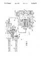
- FIG. 1is a partially-sectionalized block view of the applicable portions of a AOI CIG display system according to the invention
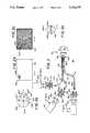
- FIGS. 2a, 2b and 2care diagrams showing images viewable at various points of interest in the system of FIG. 1;
- FIG. 3is a partially-schematic block diagram of a portion of another AOI CIG display system according to the invention, and illustrating use of a multiple image mosaic assembly having a plurality of fiber-optic elements;
- FIG. 3ais a diagram illustrating an optical pattern viewable within the assembly of FIG. 3.
- Apparatus 10includes a background projection means 11 and an area-of-interest (AOI) projection means 12 for forming an image of a high-resolution area to be inset into the relatively low-resolution scene projected from projection lens 11a of the background projector.
- An optical combination means 14, such as a beamsplitter and the like,receives the background scene illumination from lens 11a, and the inset area illumination from projector means lens 12a, and provides the blended illumination via a common relay means 16, such as a lens and the like, to servo'd optical means 18.
- This means 18includes a projection lens means 19, within a housing 19a which is slewed and moved in elevation (as shown by arrows A) by an elevation drive/sense means 20a and in azimuth (as shown by arrows B, into and out of the plane of the drawing) by an azimuth drive/sense means 20b, to allow a blended scene to be projected upon a viewable area.
- the combined optical image from beamsplitter 14is relayed by lens means 16 to the input surface 22a of a fiber-optic element 22.
- the imageis passed along flexible fiber-optic element 22 and appears at the output 22b thereof, for projection through lens means 19.
- the fiber-optic element 22comprises a bundle of optical fibers 22f, each having a proximal end 22p maintained and positioned by a first fixing means 22c.
- Each fiber 22falso has a distal end 22d which passes through an aperture 19b in the projection housing 19a (and may be buffered therefrom by a resilient washer 19c and the like) and ends at the output surface 22b.
- Another clamping means 22efixes the fiber distal ends substantially permanently into a fixed positional relationship.
- a pair of rotational DR/SNS portions 24a and 24b)may be provided if it is desired to cause the distal end 22d of the fiber-optic element in fixing ring 22e to rotate, in the direction of arrows C about the axis of the fiber-optic element in surface 22b, and thus rotate the orientation of the output image, with respect to the orientation of the image input at surface 22a.
- the image rotation propertyis further shown in FIG.
- rotation drive sense means 24is originally indexed for 0 rotation (as represented by arrow 22b')
- some initial rotation in a first selected direction(say 30 in the clockwise direction) causes the input information 22a' to exit as rotated output information 22b".
- Further rotation(say through a total angle of about 90 clockwise) causes input information 22a' to exit with another output orientation 22b'".
- the total amount of rotation(through at least 360, if required) will be determined by the particular use.
- projection focusingis carried out by movement of the fiber-optic element distal surface 22b to a desired location between a first limit position 22b, furthest from projection lens means 19, and a second limit position 22b', closest to projection lens means 19, by use of focusing means 26.
- Focusing means 26includes a focus sense means, having one or more sensor components 26a/26b, and a movement means 26c actuated by components 26a/26b for moving the ring-rotation means 24, and its associated fiber-optic element retaining ring 22e (with cable distal end 22d attached) toward or away from projection lens means 19, in the direction of arrows D.
- fiber cable movement means 26does not have to move any mirrors or other precision optical components (such as a projection lens means 19 itself) nor is movement of the entire projection head means 18 required; consequently, focus means 26 may be of less cost and complexity than the focus means previously utilized in an AOI CIG display system.
- another fiber-optic element 28can advantageously be utilized to provide even greater flexibility in the blending of high-definition inset visual information into a relatively low-definition background scene.
- the background scene illuminationis passed through a background (BG) intermediate image filter which is substantially transparent, except in the area of an outtake blockage region 30a as seen in the direction of arrows X--X, (see FIG. 2b) which is advantageously surrounded by a transition region 30b of decreasing transmission as opaque 30a is approached.
- Another (AOI) intermediate image filter 32is substantially opaque as seen in the direction of arrows Y--Y, (see FIG.
- a substantially transparent area 32aof size and shape substantially complimentary to opaque area 30a and intermediate filter 30; area 32a is surrounded by an increasingly-transmissive transition region 32b, which is substantially complimentary to increasingly-opaque transition area 30b.
- the opaque area 30aremoves the low-resolution background illumination and allows the high-resolution AOI illumination information to be inset by transparent area 32a into the same portion of the total image. This combined blended illumination information is projected by the subsequent portions of system 10.
- the opaque area 30a and transparent area 32ahave been substantially in the center of the intermediate image filters 30/32 and these filters have been positionally fixed with respect to beamsplitter 14, so that the optically-blended image required that the subsequent projection system be slewed in a servo-tracked manner to provide a dynamically changing blended image.
- each of the background intermediate image filter 30 and inset image filter 32having only a relatively small complimentary area (area 30a in filter 30 and area 32a in filter 32) which are moved in unison by a blend translation drive/sense means 34.
- a blend translation drive/sense means 34if an area of high-resolution information is to be inset, for example, in the upper left corner of the scene (because the user's eyes and head have slewed to that upper left corner), the entire projection head 18 need not be so slewed, but rather the opaque obscuration area 30a of the background image filter can be moved to the upper left corner (as shown in FIG. 2b) by the blend translation drive sense means 34, removing the low-definition information in that area.
- the high-definition image filter mask element 32is also moved so that its transparent area 32a is centered on the same portion of the relative screen, by mechanical connection to means 34, and by movement in the same directions of arrows E. It will be seen that while the obscuration of a small portion of a low-definition image can be adequately carried out by two-dimensional movement of the masking image filter 30, insertion of high-definition information at a particular location cannot be carried out by mere movement of a spot-transmissive masking filter 32 alone.
- the high-definition information input through spot 32amust closely track that spot; normally this would require placing AOI inset projector means 12 with its lens means 12a at a fixed location with respect to mask area 32a, so that the entire bulk of means 12 must be translated along with filter mask 32.
- the inset projector means 12can be maintained in a fixed location, by installing the fiber-optic element 28 to have its input surface 28a, at its proximal and 28b, receive the illumination output from projector lens 12a, and with the fibers 28f flexibly connecting proximal end 28b to distal end 28c, so that the output surface 28d can be placed at the proper fixed location with respect to image mask transparent area 32a, and fixedly maintained thereat by a holding means 30.
- the translucent area 32a of the inset mask 32can be translated, as shown by arrows E, to anyplace within the inset plane (e.g. the input plane to the bottom surface of beamsplitter 14) with movement only of the distal end of fiber-optic cable 28 and without movement either of the proximal end of that cable or of the inset projector means 12.
- the inset maskis fixed at the image plane of the fiber-optic element output, whereas the background mask is placed at an intermediate image plane prior to the combining optics. Since the inset image can be moved laterally (i.e. in the same plane as the image plane), the inset can move within the background field of view without suffering any relative geometry changes, such as keystoning or magnification.
- the background image maskcan be moved in its own image plane in a one-for-one manner with the inset image.
- the optical blend provided by this approachis capable of being moved throughout the entire background field-of-view with the blend quality remaining identical to a baseline blend, with the exception of any displacement errors between the background and inset masks occurring during movement.
- the masksare relatively small in size, and have a limited displacement range, a high degree of accuracy can be achieved at relatively low cost with relatively simple servo control.
- the relative displacement of the masksmay be imperceptible to the system user.
- the small size and displacement of the insetting mechanismallows for higher rates and accelerations to be achieved, particularly in comparison with conventional gimbal slewing projection optics.
- a portion 40 of a projection systemallows multiple video inputs, from each of a plurality of projection means 41, 42 and/or 43, to be combined to provide additional resolution, brightness and/or projected field-of-view. It is well known to the art to utilize classical optical methods (e.g. masks in conjunction with beamsplitters and the like) to combine several images containing different information, from different sources (e.g. video channels), for output to a common objective lens. In projection systems where such multiple image output through a common objective lens is required, optical throughput efficiency is typically reduced by a factor of 50 percent for each 1:1 image combination.
- data for forming the indicia "J"is provided at a first projector data input 41a, while data for forming the indicia "H” is provided at data input 42a of a second projector means, and data for forming the letter "M” is provided at the input 43a of the third projector means.
- the J/H/M illumination patternsare provided at the respective projector output means 41a/42a/43a, to the respective input surfaces 45a/46a/47a of the respective fiber-optic elements 45/46/47.
- the first cablehas a proximal end 45b which can be maintained by a fixing ring element 45c; in a similar manner proximal end 46b or 47b of fiber cable 46 or 47 is maintained by an associated fixing element 46c or 47c.
- the respective fibers 45f/46f/47f of the respective cables 45/46/47are combined into a single cable 48, having a distal end 48a which is fixed by a member 48b, so that a common fiber-optic cable end 48c provides a combined output image to a common objective lens means 50.
- the mosaic of fiber-optic elementsare here manufactured in such a manner so that the fiber array output surface 48c provides (see FIG.
- the channel images 48ca, 48cb and 48cc adjacent to one anotherwithout requiring the use of beamsplitter devices.
- the output imagecan have a portion, e.g. center portion 48cb, which is magnified with respect to the size of its input image; note also that the output of at least the projector (e.g. projectors 41 and 42) can be spatially rotated by imparting a twist in the associated cable (e.g. cable 45 and 46).
- the various image portionscan be physically separated and acted upon in order to magnify, vary the resolution, brightness and/or field-of-view, as required. This may be provided by suitably shaping the input surface (e.g.
- the fiber-optic element 45-48allows stretching, tapering, twisting and the like, during manufacturing, so that a multitude of unique and distorted output formats can be achieved.
- input and/or output surfacescan be shaped, as by grinding, etching and the like, into concave, convex or compound surfaces, so that a controllable acuity change can be achieved in the fiber-optic element.
- the fiber-optic elementacts as a "zero depth" window so that the output image does not suffer from the color anomalies typically found when using a hard optics approach.
- a clean, color-corrected image planewill thus be present at the fiber-optic cable output surface and illuminance will fall off in direct proportion to the change in area of the fiber size from input to output.
Landscapes
- Physics & Mathematics (AREA)
- General Physics & Mathematics (AREA)
- Engineering & Computer Science (AREA)
- Theoretical Computer Science (AREA)
- Optics & Photonics (AREA)
- Spectroscopy & Molecular Physics (AREA)
- Aviation & Aerospace Engineering (AREA)
- Business, Economics & Management (AREA)
- Educational Administration (AREA)
- Educational Technology (AREA)
- Optical Fibers, Optical Fiber Cores, And Optical Fiber Bundles (AREA)
- Mechanical Optical Scanning Systems (AREA)
- Projection Apparatus (AREA)
Abstract
Description
Claims (11)
Priority Applications (6)
| Application Number | Priority Date | Filing Date | Title |
|---|---|---|---|
| US07/631,236US5136675A (en) | 1990-12-20 | 1990-12-20 | Slewable projection system with fiber-optic elements |
| CA002056530ACA2056530A1 (en) | 1990-12-20 | 1991-11-28 | Slewable projection system with fiber-optic elements |
| FR9115021AFR2670913B1 (en) | 1990-12-20 | 1991-12-04 | ORIENTABLE PROJECTION SYSTEM PROVIDED WITH FIBER OPTIC ELEMENTS. |
| GB9126222AGB2253280A (en) | 1990-12-20 | 1991-12-10 | Projection system |
| DE4140786ADE4140786A1 (en) | 1990-12-20 | 1991-12-11 | SWIVELING PROJECTION SYSTEM WITH LIGHTWAVE GUIDE ELEMENTS |
| JP3353067AJPH05150712A (en) | 1990-12-20 | 1991-12-18 | Projecting apparatus that can be turned |
Applications Claiming Priority (1)
| Application Number | Priority Date | Filing Date | Title |
|---|---|---|---|
| US07/631,236US5136675A (en) | 1990-12-20 | 1990-12-20 | Slewable projection system with fiber-optic elements |
Publications (1)
| Publication Number | Publication Date |
|---|---|
| US5136675Atrue US5136675A (en) | 1992-08-04 |
Family
ID=24530333
Family Applications (1)
| Application Number | Title | Priority Date | Filing Date |
|---|---|---|---|
| US07/631,236Expired - Fee RelatedUS5136675A (en) | 1990-12-20 | 1990-12-20 | Slewable projection system with fiber-optic elements |
Country Status (6)
| Country | Link |
|---|---|
| US (1) | US5136675A (en) |
| JP (1) | JPH05150712A (en) |
| CA (1) | CA2056530A1 (en) |
| DE (1) | DE4140786A1 (en) |
| FR (1) | FR2670913B1 (en) |
| GB (1) | GB2253280A (en) |
Cited By (59)
| Publication number | Priority date | Publication date | Assignee | Title |
|---|---|---|---|---|
| US5208891A (en)* | 1991-10-07 | 1993-05-04 | The United State Of America As Represented By The Secretary Of The Navy | Fiber-optic viewgraph projector |
| US5320534A (en)* | 1990-11-05 | 1994-06-14 | The United States Of America As Represented By The Secretary Of The Air Force | Helmet mounted area of interest (HMAoI) for the display for advanced research and training (DART) |
| US5326266A (en)* | 1992-09-02 | 1994-07-05 | Evans & Sutherland Computer Corporation | Area of interest display system with opto/mechanical image combining |
| US5335304A (en)* | 1993-04-30 | 1994-08-02 | The United States Of America As Represented By The Secretary Of The Army | Connector distribution assembly for a fiber optic detector system |
| US5487665A (en)* | 1994-10-31 | 1996-01-30 | Mcdonnell Douglas Corporation | Video display system and method for generating and individually positioning high resolution inset images |
| US5715337A (en)* | 1996-09-19 | 1998-02-03 | The Mirco Optical Corporation | Compact display system |
| US5726671A (en)* | 1996-10-07 | 1998-03-10 | Hughes Electronics | Helmet/head mounted projector system |
| US5793918A (en)* | 1997-03-03 | 1998-08-11 | Hogan; Richard J. | Movable 3d display |
| US5808589A (en)* | 1994-08-24 | 1998-09-15 | Fergason; James L. | Optical system for a head mounted display combining high and low resolution images |
| EP0974863A1 (en)* | 1998-07-23 | 2000-01-26 | Kabushikigaisya Goto Kogaku Kenkyujyo | Image projection system for dome surface |
| WO2002012949A3 (en)* | 2000-08-08 | 2002-05-02 | Koninkl Philips Electronics Nv | Display device |
| US6445365B1 (en)* | 1993-03-29 | 2002-09-03 | Canon Kabushiki Kaisha | Image display apparatus and image photographing apparatus therefor |
| US20020130821A1 (en)* | 2001-03-16 | 2002-09-19 | Barry Bronson | Method and apparatus for displaying images |
| US20030016236A1 (en)* | 2001-07-18 | 2003-01-23 | Barry Bronson | Immersive augmentation for display systems |
| US6603397B2 (en) | 2001-03-14 | 2003-08-05 | Hewlett-Packard Development Company, L.P. | Control of emissions by devices in sensitive environments |
| US20050041000A1 (en)* | 2003-07-16 | 2005-02-24 | Plut William J. | Projection-type display devices with reduced weight and size |
| US20050057542A1 (en)* | 2003-07-16 | 2005-03-17 | Plut William J. | Positionable projection display devices |
| US20050218852A1 (en)* | 2004-01-28 | 2005-10-06 | Landry Gregg W | Debris sensor for cleaning apparatus |
| US7081870B2 (en) | 2001-05-09 | 2006-07-25 | Hewlett-Packard Development Company, L.P. | Wearable display and method of displaying images using a wearable display |
| US20070141538A1 (en)* | 2005-07-08 | 2007-06-21 | Quinn Edward W | Simulator utilizing a high resolution visual display |
| WO2009022178A1 (en)* | 2007-08-16 | 2009-02-19 | Bae Systems Plc | Imaging device |
| US7891818B2 (en) | 2006-12-12 | 2011-02-22 | Evans & Sutherland Computer Corporation | System and method for aligning RGB light in a single modulator projector |
| US8077378B1 (en) | 2008-11-12 | 2011-12-13 | Evans & Sutherland Computer Corporation | Calibration system and method for light modulation device |
| US8239992B2 (en) | 2007-05-09 | 2012-08-14 | Irobot Corporation | Compact autonomous coverage robot |
| WO2013003942A1 (en) | 2011-07-07 | 2013-01-10 | Ati Technologies Ulc | Viewing-focus oriented image processing |
| US8358317B2 (en) | 2008-05-23 | 2013-01-22 | Evans & Sutherland Computer Corporation | System and method for displaying a planar image on a curved surface |
| US8368339B2 (en) | 2001-01-24 | 2013-02-05 | Irobot Corporation | Robot confinement |
| US8374721B2 (en) | 2005-12-02 | 2013-02-12 | Irobot Corporation | Robot system |
| US8380350B2 (en) | 2005-12-02 | 2013-02-19 | Irobot Corporation | Autonomous coverage robot navigation system |
| US8386081B2 (en) | 2002-09-13 | 2013-02-26 | Irobot Corporation | Navigational control system for a robotic device |
| US8392021B2 (en) | 2005-02-18 | 2013-03-05 | Irobot Corporation | Autonomous surface cleaning robot for wet cleaning |
| US8387193B2 (en) | 2005-02-18 | 2013-03-05 | Irobot Corporation | Autonomous surface cleaning robot for wet and dry cleaning |
| US8390251B2 (en) | 2004-01-21 | 2013-03-05 | Irobot Corporation | Autonomous robot auto-docking and energy management systems and methods |
| US8396592B2 (en) | 2001-06-12 | 2013-03-12 | Irobot Corporation | Method and system for multi-mode coverage for an autonomous robot |
| US8412377B2 (en) | 2000-01-24 | 2013-04-02 | Irobot Corporation | Obstacle following sensor scheme for a mobile robot |
| US8417383B2 (en) | 2006-05-31 | 2013-04-09 | Irobot Corporation | Detecting robot stasis |
| US8418303B2 (en) | 2006-05-19 | 2013-04-16 | Irobot Corporation | Cleaning robot roller processing |
| US8428778B2 (en) | 2002-09-13 | 2013-04-23 | Irobot Corporation | Navigational control system for a robotic device |
| US8463438B2 (en) | 2001-06-12 | 2013-06-11 | Irobot Corporation | Method and system for multi-mode coverage for an autonomous robot |
| US8474090B2 (en) | 2002-01-03 | 2013-07-02 | Irobot Corporation | Autonomous floor-cleaning robot |
| US8515578B2 (en) | 2002-09-13 | 2013-08-20 | Irobot Corporation | Navigational control system for a robotic device |
| US8584305B2 (en) | 2005-12-02 | 2013-11-19 | Irobot Corporation | Modular robot |
| US8594840B1 (en) | 2004-07-07 | 2013-11-26 | Irobot Corporation | Celestial navigation system for an autonomous robot |
| US8600553B2 (en) | 2005-12-02 | 2013-12-03 | Irobot Corporation | Coverage robot mobility |
| US8702248B1 (en) | 2008-06-11 | 2014-04-22 | Evans & Sutherland Computer Corporation | Projection method for reducing interpixel gaps on a viewing surface |
| US8739355B2 (en) | 2005-02-18 | 2014-06-03 | Irobot Corporation | Autonomous surface cleaning robot for dry cleaning |
| US8755059B2 (en) | 2011-11-08 | 2014-06-17 | Taishita LLC | Portable multiuse projector with fiber optic projection |
| US8780342B2 (en) | 2004-03-29 | 2014-07-15 | Irobot Corporation | Methods and apparatus for position estimation using reflected light sources |
| US8788092B2 (en) | 2000-01-24 | 2014-07-22 | Irobot Corporation | Obstacle following sensor scheme for a mobile robot |
| US8800107B2 (en) | 2010-02-16 | 2014-08-12 | Irobot Corporation | Vacuum brush |
| US8930023B2 (en) | 2009-11-06 | 2015-01-06 | Irobot Corporation | Localization by learning of wave-signal distributions |
| US8972052B2 (en) | 2004-07-07 | 2015-03-03 | Irobot Corporation | Celestial navigation system for an autonomous vehicle |
| US9008835B2 (en) | 2004-06-24 | 2015-04-14 | Irobot Corporation | Remote control scheduler and method for autonomous robotic device |
| US9320398B2 (en) | 2005-12-02 | 2016-04-26 | Irobot Corporation | Autonomous coverage robots |
| US9641826B1 (en) | 2011-10-06 | 2017-05-02 | Evans & Sutherland Computer Corporation | System and method for displaying distant 3-D stereo on a dome surface |
| US10466489B1 (en) | 2019-03-29 | 2019-11-05 | Razmik Ghazaryan | Methods and apparatus for a variable-resolution screen |
| US10554940B1 (en) | 2019-03-29 | 2020-02-04 | Razmik Ghazaryan | Method and apparatus for a variable-resolution screen |
| RU206993U1 (en)* | 2020-09-25 | 2021-10-05 | Богдан Павлович Бодунов | Installation for cutting a pattern of electrodes on a metallized hemispherical surface |
| US11284053B2 (en) | 2019-03-29 | 2022-03-22 | Razmik Ghazaryan | Head-mounted display and projection screen |
Families Citing this family (6)
| Publication number | Priority date | Publication date | Assignee | Title |
|---|---|---|---|---|
| FR2711808B1 (en)* | 1993-10-22 | 1995-11-24 | Thomson Csf | Device for projecting onto a common support images intended for different observers. |
| RU2140623C1 (en)* | 1997-08-11 | 1999-10-27 | Центральный научно-исследовательский институт "Электроприбор" | Process of manufacture of relief patterns on spherical surfaces and gear for its implementation |
| DE19820357C1 (en)* | 1998-05-07 | 1999-10-07 | Roland Man Druckmasch | Method of welding seam in printer cylinder shell |
| CU23050A3 (en)* | 2000-05-10 | 2005-06-24 | Frederic Jean-Pierre Demole | VIDEO PROJECTION SYSTEM. |
| DE102012202636A1 (en)* | 2012-02-21 | 2013-08-22 | Ldt Laser Display Technology Gmbh | Projection head for a laser projector |
| DE102012202637A1 (en) | 2012-02-21 | 2013-08-22 | Ldt Laser Display Technology Gmbh | Projection head for a laser projector |
Citations (7)
| Publication number | Priority date | Publication date | Assignee | Title |
|---|---|---|---|---|
| US4439755A (en)* | 1981-06-04 | 1984-03-27 | Farrand Optical Co., Inc. | Head-up infinity display and pilot's sight |
| US4439157A (en)* | 1982-05-03 | 1984-03-27 | The United States Of America As Represented By The Secretary Of The Navy | Helmet mounted display projector |
| US4634384A (en)* | 1984-02-02 | 1987-01-06 | General Electric Company | Head and/or eye tracked optically blended display system |
| US4709985A (en)* | 1983-09-27 | 1987-12-01 | Toyo Menka Kaisha, Ltd. | Flexible optical fibers for use in viewing devices |
| US4714428A (en)* | 1985-12-19 | 1987-12-22 | General Electric Company | Method of comprehensive distortion correction for a computer image generation system |
| US4969707A (en)* | 1987-06-19 | 1990-11-13 | Hopkins Ralph C | Fiber optics viewing device |
| US4983015A (en)* | 1988-07-08 | 1991-01-08 | Thomson-Csf | System for the display of color images using an optical mixer with fibers in ordered arrangement |
Family Cites Families (3)
| Publication number | Priority date | Publication date | Assignee | Title |
|---|---|---|---|---|
| FR2252043A6 (en)* | 1973-10-25 | 1975-06-13 | Mas Roland | Panoramic cine photography viewing head - images are transmitted by light pipes to film or to closed circuit TV |
| GB2043941B (en)* | 1979-01-24 | 1983-08-17 | Redifon Simulation Ltd | Visual display apparatus |
| US4427977A (en)* | 1981-08-06 | 1984-01-24 | The United States Of America As Represented By The Secretary Of The Navy | Video image simulation apparatus |
- 1990
- 1990-12-20USUS07/631,236patent/US5136675A/ennot_activeExpired - Fee Related
- 1991
- 1991-11-28CACA002056530Apatent/CA2056530A1/ennot_activeAbandoned
- 1991-12-04FRFR9115021Apatent/FR2670913B1/ennot_activeExpired - Fee Related
- 1991-12-10GBGB9126222Apatent/GB2253280A/ennot_activeWithdrawn
- 1991-12-11DEDE4140786Apatent/DE4140786A1/ennot_activeWithdrawn
- 1991-12-18JPJP3353067Apatent/JPH05150712A/ennot_activeWithdrawn
Patent Citations (7)
| Publication number | Priority date | Publication date | Assignee | Title |
|---|---|---|---|---|
| US4439755A (en)* | 1981-06-04 | 1984-03-27 | Farrand Optical Co., Inc. | Head-up infinity display and pilot's sight |
| US4439157A (en)* | 1982-05-03 | 1984-03-27 | The United States Of America As Represented By The Secretary Of The Navy | Helmet mounted display projector |
| US4709985A (en)* | 1983-09-27 | 1987-12-01 | Toyo Menka Kaisha, Ltd. | Flexible optical fibers for use in viewing devices |
| US4634384A (en)* | 1984-02-02 | 1987-01-06 | General Electric Company | Head and/or eye tracked optically blended display system |
| US4714428A (en)* | 1985-12-19 | 1987-12-22 | General Electric Company | Method of comprehensive distortion correction for a computer image generation system |
| US4969707A (en)* | 1987-06-19 | 1990-11-13 | Hopkins Ralph C | Fiber optics viewing device |
| US4983015A (en)* | 1988-07-08 | 1991-01-08 | Thomson-Csf | System for the display of color images using an optical mixer with fibers in ordered arrangement |
Cited By (142)
| Publication number | Priority date | Publication date | Assignee | Title |
|---|---|---|---|---|
| US5320534A (en)* | 1990-11-05 | 1994-06-14 | The United States Of America As Represented By The Secretary Of The Air Force | Helmet mounted area of interest (HMAoI) for the display for advanced research and training (DART) |
| US5208891A (en)* | 1991-10-07 | 1993-05-04 | The United State Of America As Represented By The Secretary Of The Navy | Fiber-optic viewgraph projector |
| US5326266A (en)* | 1992-09-02 | 1994-07-05 | Evans & Sutherland Computer Corporation | Area of interest display system with opto/mechanical image combining |
| US6445365B1 (en)* | 1993-03-29 | 2002-09-03 | Canon Kabushiki Kaisha | Image display apparatus and image photographing apparatus therefor |
| US5335304A (en)* | 1993-04-30 | 1994-08-02 | The United States Of America As Represented By The Secretary Of The Army | Connector distribution assembly for a fiber optic detector system |
| US5808589A (en)* | 1994-08-24 | 1998-09-15 | Fergason; James L. | Optical system for a head mounted display combining high and low resolution images |
| US5487665A (en)* | 1994-10-31 | 1996-01-30 | Mcdonnell Douglas Corporation | Video display system and method for generating and individually positioning high resolution inset images |
| US5715337A (en)* | 1996-09-19 | 1998-02-03 | The Mirco Optical Corporation | Compact display system |
| US5726671A (en)* | 1996-10-07 | 1998-03-10 | Hughes Electronics | Helmet/head mounted projector system |
| US5793918A (en)* | 1997-03-03 | 1998-08-11 | Hogan; Richard J. | Movable 3d display |
| EP0974863A1 (en)* | 1998-07-23 | 2000-01-26 | Kabushikigaisya Goto Kogaku Kenkyujyo | Image projection system for dome surface |
| US8412377B2 (en) | 2000-01-24 | 2013-04-02 | Irobot Corporation | Obstacle following sensor scheme for a mobile robot |
| US9446521B2 (en) | 2000-01-24 | 2016-09-20 | Irobot Corporation | Obstacle following sensor scheme for a mobile robot |
| US8565920B2 (en) | 2000-01-24 | 2013-10-22 | Irobot Corporation | Obstacle following sensor scheme for a mobile robot |
| US8788092B2 (en) | 2000-01-24 | 2014-07-22 | Irobot Corporation | Obstacle following sensor scheme for a mobile robot |
| US8761935B2 (en) | 2000-01-24 | 2014-06-24 | Irobot Corporation | Obstacle following sensor scheme for a mobile robot |
| US8478442B2 (en) | 2000-01-24 | 2013-07-02 | Irobot Corporation | Obstacle following sensor scheme for a mobile robot |
| US9144361B2 (en) | 2000-04-04 | 2015-09-29 | Irobot Corporation | Debris sensor for cleaning apparatus |
| WO2002012949A3 (en)* | 2000-08-08 | 2002-05-02 | Koninkl Philips Electronics Nv | Display device |
| US9582005B2 (en) | 2001-01-24 | 2017-02-28 | Irobot Corporation | Robot confinement |
| US9167946B2 (en) | 2001-01-24 | 2015-10-27 | Irobot Corporation | Autonomous floor cleaning robot |
| US8368339B2 (en) | 2001-01-24 | 2013-02-05 | Irobot Corporation | Robot confinement |
| US9622635B2 (en) | 2001-01-24 | 2017-04-18 | Irobot Corporation | Autonomous floor-cleaning robot |
| US9038233B2 (en) | 2001-01-24 | 2015-05-26 | Irobot Corporation | Autonomous floor-cleaning robot |
| US8686679B2 (en) | 2001-01-24 | 2014-04-01 | Irobot Corporation | Robot confinement |
| US6603397B2 (en) | 2001-03-14 | 2003-08-05 | Hewlett-Packard Development Company, L.P. | Control of emissions by devices in sensitive environments |
| US20020130821A1 (en)* | 2001-03-16 | 2002-09-19 | Barry Bronson | Method and apparatus for displaying images |
| US7091929B2 (en) | 2001-03-16 | 2006-08-15 | Hewlett-Packard Development Company, L.P. | Method and apparatus for displaying images |
| US7081870B2 (en) | 2001-05-09 | 2006-07-25 | Hewlett-Packard Development Company, L.P. | Wearable display and method of displaying images using a wearable display |
| US9104204B2 (en) | 2001-06-12 | 2015-08-11 | Irobot Corporation | Method and system for multi-mode coverage for an autonomous robot |
| US8396592B2 (en) | 2001-06-12 | 2013-03-12 | Irobot Corporation | Method and system for multi-mode coverage for an autonomous robot |
| US8463438B2 (en) | 2001-06-12 | 2013-06-11 | Irobot Corporation | Method and system for multi-mode coverage for an autonomous robot |
| US7071897B2 (en) | 2001-07-18 | 2006-07-04 | Hewlett-Packard Development Company, L.P. | Immersive augmentation for display systems |
| US20030016236A1 (en)* | 2001-07-18 | 2003-01-23 | Barry Bronson | Immersive augmentation for display systems |
| US8474090B2 (en) | 2002-01-03 | 2013-07-02 | Irobot Corporation | Autonomous floor-cleaning robot |
| US8516651B2 (en) | 2002-01-03 | 2013-08-27 | Irobot Corporation | Autonomous floor-cleaning robot |
| US9128486B2 (en) | 2002-01-24 | 2015-09-08 | Irobot Corporation | Navigational control system for a robotic device |
| US8793020B2 (en) | 2002-09-13 | 2014-07-29 | Irobot Corporation | Navigational control system for a robotic device |
| US8386081B2 (en) | 2002-09-13 | 2013-02-26 | Irobot Corporation | Navigational control system for a robotic device |
| US8428778B2 (en) | 2002-09-13 | 2013-04-23 | Irobot Corporation | Navigational control system for a robotic device |
| US8515578B2 (en) | 2002-09-13 | 2013-08-20 | Irobot Corporation | Navigational control system for a robotic device |
| US9949608B2 (en) | 2002-09-13 | 2018-04-24 | Irobot Corporation | Navigational control system for a robotic device |
| US8781626B2 (en) | 2002-09-13 | 2014-07-15 | Irobot Corporation | Navigational control system for a robotic device |
| US20050057542A1 (en)* | 2003-07-16 | 2005-03-17 | Plut William J. | Positionable projection display devices |
| US20070205300A1 (en)* | 2003-07-16 | 2007-09-06 | Plut William J | Positioning interfaces for projection display devices |
| US20050041000A1 (en)* | 2003-07-16 | 2005-02-24 | Plut William J. | Projection-type display devices with reduced weight and size |
| US8641209B2 (en) | 2003-07-16 | 2014-02-04 | Transpacific Image, Llc | Positioning interfaces for projection display devices |
| US7156522B2 (en) | 2003-07-16 | 2007-01-02 | Plut William J | Projection-type display devices with reduced weight and size |
| US20070195276A1 (en)* | 2003-07-16 | 2007-08-23 | Plut William J | Projection-type display devices with reduced speckle |
| US8366282B2 (en) | 2003-07-16 | 2013-02-05 | Transpacific Image, Llc | Positioning interfaces for projection display devices |
| US8147074B2 (en) | 2003-07-16 | 2012-04-03 | Transpacific Image, Llc | Positioning interfaces for projection display devices |
| US7281807B2 (en) | 2003-07-16 | 2007-10-16 | Honeywood Technologies, Llc | Positionable projection display devices |
| US7510284B2 (en) | 2003-07-16 | 2009-03-31 | Plut William J | Projection-type display devices including redundant laser sets |
| USRE42251E1 (en)* | 2003-07-16 | 2011-03-29 | Transpacific Image, Llc | Projection-type display devices with reduced weight and size |
| US7703930B2 (en) | 2003-07-16 | 2010-04-27 | Plut William J | Positioning interfaces for projection display devices |
| US7806535B2 (en) | 2003-07-16 | 2010-10-05 | Plut William J | Low power projection display devices |
| US20100171936A1 (en)* | 2003-07-16 | 2010-07-08 | Plut William J | Positioning interfaces for projection display devices |
| US8390251B2 (en) | 2004-01-21 | 2013-03-05 | Irobot Corporation | Autonomous robot auto-docking and energy management systems and methods |
| US8461803B2 (en) | 2004-01-21 | 2013-06-11 | Irobot Corporation | Autonomous robot auto-docking and energy management systems and methods |
| US8749196B2 (en) | 2004-01-21 | 2014-06-10 | Irobot Corporation | Autonomous robot auto-docking and energy management systems and methods |
| US8854001B2 (en) | 2004-01-21 | 2014-10-07 | Irobot Corporation | Autonomous robot auto-docking and energy management systems and methods |
| US9215957B2 (en) | 2004-01-21 | 2015-12-22 | Irobot Corporation | Autonomous robot auto-docking and energy management systems and methods |
| US20050218852A1 (en)* | 2004-01-28 | 2005-10-06 | Landry Gregg W | Debris sensor for cleaning apparatus |
| US8456125B2 (en) | 2004-01-28 | 2013-06-04 | Irobot Corporation | Debris sensor for cleaning apparatus |
| US8598829B2 (en) | 2004-01-28 | 2013-12-03 | Irobot Corporation | Debris sensor for cleaning apparatus |
| US8253368B2 (en) | 2004-01-28 | 2012-08-28 | Irobot Corporation | Debris sensor for cleaning apparatus |
| US8378613B2 (en) | 2004-01-28 | 2013-02-19 | Irobot Corporation | Debris sensor for cleaning apparatus |
| US8780342B2 (en) | 2004-03-29 | 2014-07-15 | Irobot Corporation | Methods and apparatus for position estimation using reflected light sources |
| US9360300B2 (en) | 2004-03-29 | 2016-06-07 | Irobot Corporation | Methods and apparatus for position estimation using reflected light sources |
| US9008835B2 (en) | 2004-06-24 | 2015-04-14 | Irobot Corporation | Remote control scheduler and method for autonomous robotic device |
| US9486924B2 (en) | 2004-06-24 | 2016-11-08 | Irobot Corporation | Remote control scheduler and method for autonomous robotic device |
| US8634956B1 (en) | 2004-07-07 | 2014-01-21 | Irobot Corporation | Celestial navigation system for an autonomous robot |
| US8594840B1 (en) | 2004-07-07 | 2013-11-26 | Irobot Corporation | Celestial navigation system for an autonomous robot |
| US8874264B1 (en) | 2004-07-07 | 2014-10-28 | Irobot Corporation | Celestial navigation system for an autonomous robot |
| US9223749B2 (en) | 2004-07-07 | 2015-12-29 | Irobot Corporation | Celestial navigation system for an autonomous vehicle |
| US9229454B1 (en) | 2004-07-07 | 2016-01-05 | Irobot Corporation | Autonomous mobile robot system |
| US8972052B2 (en) | 2004-07-07 | 2015-03-03 | Irobot Corporation | Celestial navigation system for an autonomous vehicle |
| US8966707B2 (en) | 2005-02-18 | 2015-03-03 | Irobot Corporation | Autonomous surface cleaning robot for dry cleaning |
| US8739355B2 (en) | 2005-02-18 | 2014-06-03 | Irobot Corporation | Autonomous surface cleaning robot for dry cleaning |
| US8387193B2 (en) | 2005-02-18 | 2013-03-05 | Irobot Corporation | Autonomous surface cleaning robot for wet and dry cleaning |
| US8985127B2 (en) | 2005-02-18 | 2015-03-24 | Irobot Corporation | Autonomous surface cleaning robot for wet cleaning |
| US8392021B2 (en) | 2005-02-18 | 2013-03-05 | Irobot Corporation | Autonomous surface cleaning robot for wet cleaning |
| US8774966B2 (en) | 2005-02-18 | 2014-07-08 | Irobot Corporation | Autonomous surface cleaning robot for wet and dry cleaning |
| US10470629B2 (en) | 2005-02-18 | 2019-11-12 | Irobot Corporation | Autonomous surface cleaning robot for dry cleaning |
| US9445702B2 (en) | 2005-02-18 | 2016-09-20 | Irobot Corporation | Autonomous surface cleaning robot for wet and dry cleaning |
| US8670866B2 (en) | 2005-02-18 | 2014-03-11 | Irobot Corporation | Autonomous surface cleaning robot for wet and dry cleaning |
| US8782848B2 (en) | 2005-02-18 | 2014-07-22 | Irobot Corporation | Autonomous surface cleaning robot for dry cleaning |
| US8855813B2 (en) | 2005-02-18 | 2014-10-07 | Irobot Corporation | Autonomous surface cleaning robot for wet and dry cleaning |
| US20070141538A1 (en)* | 2005-07-08 | 2007-06-21 | Quinn Edward W | Simulator utilizing a high resolution visual display |
| US8661605B2 (en) | 2005-12-02 | 2014-03-04 | Irobot Corporation | Coverage robot mobility |
| US8584305B2 (en) | 2005-12-02 | 2013-11-19 | Irobot Corporation | Modular robot |
| US8600553B2 (en) | 2005-12-02 | 2013-12-03 | Irobot Corporation | Coverage robot mobility |
| US9320398B2 (en) | 2005-12-02 | 2016-04-26 | Irobot Corporation | Autonomous coverage robots |
| US9599990B2 (en) | 2005-12-02 | 2017-03-21 | Irobot Corporation | Robot system |
| US9149170B2 (en) | 2005-12-02 | 2015-10-06 | Irobot Corporation | Navigating autonomous coverage robots |
| US8954192B2 (en) | 2005-12-02 | 2015-02-10 | Irobot Corporation | Navigating autonomous coverage robots |
| US9392920B2 (en) | 2005-12-02 | 2016-07-19 | Irobot Corporation | Robot system |
| US9144360B2 (en) | 2005-12-02 | 2015-09-29 | Irobot Corporation | Autonomous coverage robot navigation system |
| US8761931B2 (en) | 2005-12-02 | 2014-06-24 | Irobot Corporation | Robot system |
| US8978196B2 (en) | 2005-12-02 | 2015-03-17 | Irobot Corporation | Coverage robot mobility |
| US8374721B2 (en) | 2005-12-02 | 2013-02-12 | Irobot Corporation | Robot system |
| US8380350B2 (en) | 2005-12-02 | 2013-02-19 | Irobot Corporation | Autonomous coverage robot navigation system |
| US10244915B2 (en) | 2006-05-19 | 2019-04-02 | Irobot Corporation | Coverage robots and associated cleaning bins |
| US9955841B2 (en) | 2006-05-19 | 2018-05-01 | Irobot Corporation | Removing debris from cleaning robots |
| US9492048B2 (en) | 2006-05-19 | 2016-11-15 | Irobot Corporation | Removing debris from cleaning robots |
| US8572799B2 (en) | 2006-05-19 | 2013-11-05 | Irobot Corporation | Removing debris from cleaning robots |
| US8528157B2 (en) | 2006-05-19 | 2013-09-10 | Irobot Corporation | Coverage robots and associated cleaning bins |
| US8418303B2 (en) | 2006-05-19 | 2013-04-16 | Irobot Corporation | Cleaning robot roller processing |
| US9317038B2 (en) | 2006-05-31 | 2016-04-19 | Irobot Corporation | Detecting robot stasis |
| US8417383B2 (en) | 2006-05-31 | 2013-04-09 | Irobot Corporation | Detecting robot stasis |
| US7891818B2 (en) | 2006-12-12 | 2011-02-22 | Evans & Sutherland Computer Corporation | System and method for aligning RGB light in a single modulator projector |
| US8839477B2 (en) | 2007-05-09 | 2014-09-23 | Irobot Corporation | Compact autonomous coverage robot |
| US8726454B2 (en) | 2007-05-09 | 2014-05-20 | Irobot Corporation | Autonomous coverage robot |
| US11498438B2 (en) | 2007-05-09 | 2022-11-15 | Irobot Corporation | Autonomous coverage robot |
| US11072250B2 (en) | 2007-05-09 | 2021-07-27 | Irobot Corporation | Autonomous coverage robot sensing |
| US8239992B2 (en) | 2007-05-09 | 2012-08-14 | Irobot Corporation | Compact autonomous coverage robot |
| US9480381B2 (en) | 2007-05-09 | 2016-11-01 | Irobot Corporation | Compact autonomous coverage robot |
| US10299652B2 (en) | 2007-05-09 | 2019-05-28 | Irobot Corporation | Autonomous coverage robot |
| US10070764B2 (en) | 2007-05-09 | 2018-09-11 | Irobot Corporation | Compact autonomous coverage robot |
| US8438695B2 (en) | 2007-05-09 | 2013-05-14 | Irobot Corporation | Autonomous coverage robot sensing |
| US8110791B2 (en) | 2007-08-16 | 2012-02-07 | Bae Systems Plc | Imaging device |
| US20100200736A1 (en)* | 2007-08-16 | 2010-08-12 | Leslie Charles Laycock | Imaging device |
| WO2009022178A1 (en)* | 2007-08-16 | 2009-02-19 | Bae Systems Plc | Imaging device |
| US8358317B2 (en) | 2008-05-23 | 2013-01-22 | Evans & Sutherland Computer Corporation | System and method for displaying a planar image on a curved surface |
| US8702248B1 (en) | 2008-06-11 | 2014-04-22 | Evans & Sutherland Computer Corporation | Projection method for reducing interpixel gaps on a viewing surface |
| US8077378B1 (en) | 2008-11-12 | 2011-12-13 | Evans & Sutherland Computer Corporation | Calibration system and method for light modulation device |
| US8930023B2 (en) | 2009-11-06 | 2015-01-06 | Irobot Corporation | Localization by learning of wave-signal distributions |
| US8800107B2 (en) | 2010-02-16 | 2014-08-12 | Irobot Corporation | Vacuum brush |
| US11058271B2 (en) | 2010-02-16 | 2021-07-13 | Irobot Corporation | Vacuum brush |
| US10314449B2 (en) | 2010-02-16 | 2019-06-11 | Irobot Corporation | Vacuum brush |
| CN103797510A (en)* | 2011-07-07 | 2014-05-14 | Ati科技无限责任公司 | View Image Processing for Focus Orientation |
| EP2729914A4 (en)* | 2011-07-07 | 2015-02-18 | Ati Technologies Ulc | IMAGE PROCESSING ORIENTED TO FOCUS POINT |
| WO2013003942A1 (en) | 2011-07-07 | 2013-01-10 | Ati Technologies Ulc | Viewing-focus oriented image processing |
| US10110876B1 (en) | 2011-10-06 | 2018-10-23 | Evans & Sutherland Computer Corporation | System and method for displaying images in 3-D stereo |
| US9641826B1 (en) | 2011-10-06 | 2017-05-02 | Evans & Sutherland Computer Corporation | System and method for displaying distant 3-D stereo on a dome surface |
| US8755059B2 (en) | 2011-11-08 | 2014-06-17 | Taishita LLC | Portable multiuse projector with fiber optic projection |
| US10466489B1 (en) | 2019-03-29 | 2019-11-05 | Razmik Ghazaryan | Methods and apparatus for a variable-resolution screen |
| US10554940B1 (en) | 2019-03-29 | 2020-02-04 | Razmik Ghazaryan | Method and apparatus for a variable-resolution screen |
| US10649217B1 (en) | 2019-03-29 | 2020-05-12 | Razmik Ghazaryan | Method and apparatus for a variable-resolution screen |
| US10958884B1 (en) | 2019-03-29 | 2021-03-23 | Razmik Ghazaryan | Method and apparatus for a variable-resolution screen |
| US11284053B2 (en) | 2019-03-29 | 2022-03-22 | Razmik Ghazaryan | Head-mounted display and projection screen |
| RU206993U1 (en)* | 2020-09-25 | 2021-10-05 | Богдан Павлович Бодунов | Installation for cutting a pattern of electrodes on a metallized hemispherical surface |
Also Published As
| Publication number | Publication date |
|---|---|
| FR2670913A1 (en) | 1992-06-26 |
| CA2056530A1 (en) | 1992-06-21 |
| JPH05150712A (en) | 1993-06-18 |
| GB9126222D0 (en) | 1992-02-12 |
| DE4140786A1 (en) | 1992-06-25 |
| GB2253280A (en) | 1992-09-02 |
| FR2670913B1 (en) | 1995-01-20 |
Similar Documents
| Publication | Publication Date | Title |
|---|---|---|
| US5136675A (en) | Slewable projection system with fiber-optic elements | |
| US6008951A (en) | Offset projection zoom lens with fixed rear group for reflective spatial light modulators | |
| CA2142715C (en) | Projection system for projecting a color video picture and transformation optical system for same | |
| US6550918B1 (en) | Monocentric autostereoscopic viewing apparatus using resonant fiber-optic image generation | |
| JP4233357B2 (en) | Autostereoscopic equipment | |
| JP3489841B2 (en) | Display device incorporating a one-dimensional high-speed grating light valve array | |
| US5914818A (en) | Offset projection lens for use with reflective spatial light modulators | |
| KR20200070256A (en) | Axial asymmetric image source for head-up display | |
| CN100378504C (en) | Decentered lens group for use in an off-axis projector | |
| EP0704739A2 (en) | Image display systems | |
| EP0435523A2 (en) | Helmet display | |
| US5535025A (en) | Helmet mounted off axis liquid crystal display with a fiber optic wedge and a curved reflector | |
| CA2457773A1 (en) | Projection display device and back projection display device using the display device | |
| US5319490A (en) | Helmet mounted display including synchronously moving tilted mechanisms | |
| US6784946B1 (en) | Assembly, in which light from a light source is directed onto a surface | |
| KR19980702527A (en) | Optical scanning method and apparatus for single panel color projection video display | |
| GB2313220A (en) | Split beam optical character reader | |
| US3055265A (en) | Motion picture camera for making panoramic pictures | |
| US6394601B1 (en) | Spectacle-mounted micro display ocular | |
| US20020001030A1 (en) | Three-dimensional display apparatus and oblique projection optical system | |
| EP1309893B1 (en) | Display device | |
| WO2005033777A1 (en) | Autostereoscopic optical apparatus | |
| US7177080B2 (en) | Method and a device for bi-monocular image transfer | |
| US5730517A (en) | Projector | |
| US5285307A (en) | Visual field expanding system |
Legal Events
| Date | Code | Title | Description |
|---|---|---|---|
| AS | Assignment | Owner name:GENERAL ELECTRIC COMPANY, A CORP. OF NEW YORK Free format text:ASSIGNMENT OF ASSIGNORS INTEREST.;ASSIGNOR:HODSON, JAMES M.;REEL/FRAME:005558/0729 Effective date:19901214 | |
| FEPP | Fee payment procedure | Free format text:PAYOR NUMBER ASSIGNED (ORIGINAL EVENT CODE: ASPN); ENTITY STATUS OF PATENT OWNER: LARGE ENTITY | |
| AS | Assignment | Owner name:MARTIN MARIETTA CORPORATION, MARYLAND Free format text:ASSIGNMENT OF ASSIGNORS INTEREST;ASSIGNOR:GENERAL ELECTRIC COMPANY;REEL/FRAME:007046/0736 Effective date:19940322 | |
| REMI | Maintenance fee reminder mailed | ||
| LAPS | Lapse for failure to pay maintenance fees | ||
| FP | Lapsed due to failure to pay maintenance fee | Effective date:19960807 | |
| AS | Assignment | Owner name:LOCKHEED MARTIN CORPORATION, MARYLAND Free format text:ASSIGNMENT OF ASSIGNORS INTEREST;ASSIGNOR:MARTIN MARIETTA CORPORATION;REEL/FRAME:008628/0518 Effective date:19960128 | |
| FEPP | Fee payment procedure | Free format text:PAYOR NUMBER ASSIGNED (ORIGINAL EVENT CODE: ASPN); ENTITY STATUS OF PATENT OWNER: LARGE ENTITY Free format text:PAYER NUMBER DE-ASSIGNED (ORIGINAL EVENT CODE: RMPN); ENTITY STATUS OF PATENT OWNER: LARGE ENTITY | |
| STCH | Information on status: patent discontinuation | Free format text:PATENT EXPIRED DUE TO NONPAYMENT OF MAINTENANCE FEES UNDER 37 CFR 1.362 |