US5136268A - Miniature dual mode planar filters - Google Patents
Miniature dual mode planar filtersDownload PDFInfo
- Publication number
- US5136268A US5136268AUS07/688,038US68803891AUS5136268AUS 5136268 AUS5136268 AUS 5136268AUS 68803891 AUS68803891 AUS 68803891AUS 5136268 AUS5136268 AUS 5136268A
- Authority
- US
- United States
- Prior art keywords
- resonator
- resonating
- electromagnetic signals
- filter
- coupling
- Prior art date
- Legal status (The legal status is an assumption and is not a legal conclusion. Google has not performed a legal analysis and makes no representation as to the accuracy of the status listed.)
- Expired - Lifetime
Links
Images


Classifications
- H—ELECTRICITY
- H01—ELECTRIC ELEMENTS
- H01P—WAVEGUIDES; RESONATORS, LINES, OR OTHER DEVICES OF THE WAVEGUIDE TYPE
- H01P1/00—Auxiliary devices
- H01P1/20—Frequency-selective devices, e.g. filters
- H01P1/201—Filters for transverse electromagnetic waves
- H01P1/203—Strip line filters
- H01P1/20327—Electromagnetic interstage coupling
- H01P1/20354—Non-comb or non-interdigital filters
- H01P1/20381—Special shape resonators
- H—ELECTRICITY
- H01—ELECTRIC ELEMENTS
- H01P—WAVEGUIDES; RESONATORS, LINES, OR OTHER DEVICES OF THE WAVEGUIDE TYPE
- H01P7/00—Resonators of the waveguide type
- H01P7/08—Strip line resonators
- H01P7/082—Microstripline resonators
- H—ELECTRICITY
- H01—ELECTRIC ELEMENTS
- H01P—WAVEGUIDES; RESONATORS, LINES, OR OTHER DEVICES OF THE WAVEGUIDE TYPE
- H01P7/00—Resonators of the waveguide type
- H01P7/08—Strip line resonators
- H01P7/084—Triplate line resonators
- Y—GENERAL TAGGING OF NEW TECHNOLOGICAL DEVELOPMENTS; GENERAL TAGGING OF CROSS-SECTIONAL TECHNOLOGIES SPANNING OVER SEVERAL SECTIONS OF THE IPC; TECHNICAL SUBJECTS COVERED BY FORMER USPC CROSS-REFERENCE ART COLLECTIONS [XRACs] AND DIGESTS
- Y10—TECHNICAL SUBJECTS COVERED BY FORMER USPC
- Y10S—TECHNICAL SUBJECTS COVERED BY FORMER USPC CROSS-REFERENCE ART COLLECTIONS [XRACs] AND DIGESTS
- Y10S505/00—Superconductor technology: apparatus, material, process
- Y10S505/825—Apparatus per se, device per se, or process of making or operating same
- Y10S505/866—Wave transmission line, network, waveguide, or microwave storage device
Definitions
- This inventionrelates to high frequency electronic circuits, and more particularly to microwave communication filters implemented using planar transmission line fabrication techniques.
- Microstripis formed by etching a circuit pattern on one side of two metal layers separated by a dielectric substrate. The unetched side serves as a ground plane.
- Stripline circuitsare fabricated by etching a metal layer sandwiched between two dielectric layers having outer surfaces coated by metal ground planes.
- FIG. 1shows the resonator 2 of Snell having a rectangular shape with side lengths of 1 1 and 1 2 .
- Signal conductors 4are used to couple signals to and from resonator 2. Accordingly, the element supports two resonant orthogonal standing waves, and external coupling to each wave can be provided independently.
- an adjustable notch in a slot line ringis disclosed for tuning the center frequency and bandwidth of a microwave filter.
- a dual mode microstrip resonator (1)is used in the design of high performance microwave communication circuits.
- a perturbationis added to dual mode resonator (2) of the prior art (shown in FIG. 1) at a point that lies on an axis of symmetry (6) formed by the bisection of characteristic vectors (13,15).
- Vectors (13,15)represent orthogonal dual modes which characterize the resonator (2) of the prior art.
- This perturbation added to resonator (1)facilitates coupling between the two orthogonal modes within resonator (1).
- each resonator (1)can be used to realize a second order transfer functions (having two frequency poles). Combining multiple resonators (1) enables the efficient realization of higher order filter circuits.
- FIG. 1is a top view of a prior art microstrip type planar transmission line illustrating a dual mode resonator 2;
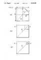
- FIG. 2(a)is a top view of a dual mode microstrip type resonator 1 comprising notch 3;
- FIG. 2(b)is a top view of a dual mode microstrip type resonator 9 comprising stub 5;
- FIG. 2(c)is a top view of a dual mode microstrip type resonator 11 comprising hole 7;
- FIG. 3is a top view of a dual mode microstrip type filter 45 comprising resonator 35 of the present invention and coupling transmission lines 37, 39, 41 and 43;
- FIG. 4is a relief view of a fourth order filter utilizing dual mode resonators 20, 22 of the present invention.
- FIG. 5is a top view of an eighth order filter utilizing dual mode resonators 63 of the present invention.
- FIG. 6is a top view of an eighth order filter utilizing dual mode resonators 77 of the present invention.
- resonator 1is substantially square in shape, having side lengths 1 3 and 1 4 which are equal to the half wave lengths of the orthogonal resonant signals represented by characteristic vectors 13 and 15 respectively.
- Vectors 13 and 15are bisected by axis of symmetry 6.
- Coupling notch 3lies perpendicular to axis of symmetry 6 in such a manner that axis 6 bisects the notch 3.
- Coupling notch 3causes each of the resonant signals represented by vectors 13 and 15 to symmetrically reflect nd couple with the corresponding signal in the orthogonal direction.
- any placement of the notch 3 which distorts the signalwill effect coupling of the orthogonal signals.
- Characteristic vectors 13, 15can be drawn in any orientation such that they are parallel to the edges of the resonator, and the notch 3 can be placed accordingly with respect to a bisecting axis of symmetry 6, as described above. It is also possible to effect coupling by using multiple notches 3 or perturbations located in various corners of resonator 1. The variability of notch orientation is demonstrated in FIG. 5 where notches 67 alternate. In FIG. 6, three of the resonators 77 have three notches 79 which are oriented to the interior of the circuit while a fourth is randomly oriented outward.
- substantially square resonator 1provides an advantage over narrow single mode resonant filters by providing higher Q, since the losses are reduced by the wide geometrical dimensions available in the direction of resonance. These Q factors are significantly improved when superconductive materials are used in constructing the circuitry. Also, the use of substantially square resonators facilitates the realization of dual mode designs and elliptic functions and self equalized planar filter designs.
- a resonator 9 of the present inventionis shown with a stub 5 perturbation.
- This stub 5operates as an alternative to notch 3 in FIG. 2(a), to couple together the two independent orthogonal modes traversing resonator 9.
- This stub 5can be constructed in any symmetrical shape and of any material which perturbs the electromagnetic fields resident on resonator 9.
- the stub 5can be formed by depositing a metallic or dielectric material on the surface of resonator 9.
- the shape of stub 5is not critical except that the geometry should produce a symmetrical signal reflection (half on each side) relative to axis of symmetry 19.
- FIG. 2(c)shows a resonator 11 which uses a hole 7 as a coupling means instead of stub 5.
- the holeshould produce a symmetrical signal reflection relative to axis of symmetry 21.
- Input conductor leads 37 and 39are used to provide electromagnetic signals to resonator 35.
- the inputs 37, 39 and outputs 41, 43are capacitively coupled to resonator 35 through gaps C1-C4 respectively.
- the signal entering resonator 35 from input 37introduces an electromagnetic signal which resonates along characteristic vector 31.
- Input conductor lead 39introduces a signal which resonates along characteristic vector 33 orthogonal to vector 31.
- Notch 47causes each of the resonant signals represented by vectors 31 and 33 to symmetrically reflect and couple with the corresponding signal in the orthogonal direction. Coupling between the inputs 37, 39 and resonator 35 is arranged so that the input 37, 38 strips are centered with respect to the edge of the resonator 47. Although this configuration provides coupling at a point of maximum resonant signal strength, alternate coupling schemes are well known in the art as disclosed by U.S. Pat. No. 3,796,970. Output 41 and output 43 are used to deliver coupled signal components from resonator 35.
- FIG. 4a relief view of a fourth order filter utilizing dual mode resonators 20, 22 of the present invention is shown.
- the circuit structureis fabricated by constructing dielectric substrate 30 over conductive ground plane 28.
- Various circuit components 16, 20, 24, 22, 18are then deposited or etched using microstrip or strip line planar fabrication techniques.
- conductor lead 16provides an input signal to resonator 20.
- the dual pole generation of resonator 25is effected through the notch 26 coupling of orthogonal signal components.
- the second order signalis then transmitted along conductor lead 24 to the second resonator element 22 where additional second order filtering is introduced.
- the output signal of this fourth order circuitis sampled along output 18.
- FIG. 5an eighth order filter using four dual mode resonators 63 of the present invention is shown.
- the input signalis continuously sampled at input 61, filtered through resonator elements 63, and coupled by conductor leads 65.
- the eighth order output of this filter structureis sampled by output 69.
- FIG. 6an alternative embodiment of an eighth order filter using dual mode resonators 77 of the present invention is shown.
- the input signal to this circuitis provided through input 81.
- Resonators 77each provide a second order (two pole) effect through coupling of two orthogonal components facilitated by notches 79.
- the individual resonator elements 77are coupled together by conductor leads 75, and the circuit is sampled at output 83.
Landscapes
- Physics & Mathematics (AREA)
- Electromagnetism (AREA)
- Control Of Motors That Do Not Use Commutators (AREA)
Abstract
Description
Claims (9)
Priority Applications (5)
| Application Number | Priority Date | Filing Date | Title |
|---|---|---|---|
| US07/688,038US5136268A (en) | 1991-04-19 | 1991-04-19 | Miniature dual mode planar filters |
| DE69210460TDE69210460T2 (en) | 1991-04-19 | 1992-03-11 | Planar miniature dual mode filters |
| EP92302069AEP0509636B1 (en) | 1991-04-19 | 1992-03-11 | Miniature dual mode planar filters |
| CA002063119ACA2063119C (en) | 1991-04-19 | 1992-03-16 | Miniature dual mode planar filters |
| JP4121089AJP2589247B2 (en) | 1991-04-19 | 1992-04-16 | Compact dual-mode planar filter |
Applications Claiming Priority (1)
| Application Number | Priority Date | Filing Date | Title |
|---|---|---|---|
| US07/688,038US5136268A (en) | 1991-04-19 | 1991-04-19 | Miniature dual mode planar filters |
Publications (1)
| Publication Number | Publication Date |
|---|---|
| US5136268Atrue US5136268A (en) | 1992-08-04 |
Family
ID=24762863
Family Applications (1)
| Application Number | Title | Priority Date | Filing Date |
|---|---|---|---|
| US07/688,038Expired - LifetimeUS5136268A (en) | 1991-04-19 | 1991-04-19 | Miniature dual mode planar filters |
Country Status (5)
| Country | Link |
|---|---|
| US (1) | US5136268A (en) |
| EP (1) | EP0509636B1 (en) |
| JP (1) | JP2589247B2 (en) |
| CA (1) | CA2063119C (en) |
| DE (1) | DE69210460T2 (en) |
Cited By (25)
| Publication number | Priority date | Publication date | Assignee | Title |
|---|---|---|---|---|
| US5400002A (en)* | 1992-06-12 | 1995-03-21 | Matsushita Electric Industrial Co., Ltd. | Strip dual mode filter in which a resonance width of a microwave is adjusted and dual mode multistage filter in which the strip dual mode filters are arranged in series |
| US5484764A (en)* | 1992-11-13 | 1996-01-16 | Space Systems/Loral, Inc. | Plural-mode stacked resonator filter including superconductive material resonators |
| US5703546A (en)* | 1992-04-30 | 1997-12-30 | Matsushita Electric Industrial Co., Ltd. | Strip line filter having dual mode loop resonators |
| US5750473A (en)* | 1995-05-11 | 1998-05-12 | E. I. Du Pont De Nemours And Company | Planar high temperature superconductor filters with backside coupling |
| US5786303A (en)* | 1994-06-22 | 1998-07-28 | Com Dev Ltd. | Planar multi-resonator bandpass filter |
| US5805034A (en)* | 1995-03-17 | 1998-09-08 | Lucent Technologies Inc. | Microstrip patch filters |
| US5889449A (en)* | 1995-12-07 | 1999-03-30 | Space Systems/Loral, Inc. | Electromagnetic transmission line elements having a boundary between materials of high and low dielectric constants |
| US5939958A (en)* | 1997-02-18 | 1999-08-17 | The United States Of America As Represented By The Secretary Of The Navy | Microstrip dual mode elliptic filter with modal coupling through patch spacing |
| US6016434A (en)* | 1994-06-17 | 2000-01-18 | Matsushita Electric Industrial Co., Ltd. | High-frequency circuit element in which a resonator and input/ouputs are relatively movable |
| US6114931A (en)* | 1995-12-19 | 2000-09-05 | Telefonaktiebolaget Lm Ericsson | Superconducting arrangement with non-orthogonal degenerate resonator modes |
| US6187717B1 (en)* | 1995-06-13 | 2001-02-13 | Telefonaktiebolaget Lm Ericsson | Arrangement and method relating to tunable devices through the controlling of plasma surface waves |
| US20020149447A1 (en)* | 2000-02-24 | 2002-10-17 | Murata Manufacturing Co., Ltd. | Method of producing band-pass filter and band-pass filter |
| US6476686B1 (en)* | 2001-09-21 | 2002-11-05 | Space Systems/Loral, Inc. | Dielectric resonator equalizer |
| US6556109B2 (en)* | 2000-05-23 | 2003-04-29 | Murata Manufacturing Co., Ltd. | Dual mode band pass filter |
| US20030087765A1 (en)* | 1993-05-28 | 2003-05-08 | Superconductor Technologies, Inc. | High temperature superconducting structures and methods for high Q, reduced intermodulation structures |
| US6563403B2 (en)* | 2000-05-29 | 2003-05-13 | Murata Manufacturing Co., Ltd. | Dual mode band-pass filter |
| US20030151472A1 (en)* | 2002-02-08 | 2003-08-14 | Kundu Arun Chandra | TEM dual-mode rectangular dielectric waveguide bandpass filter |
| US20030222732A1 (en)* | 2002-05-29 | 2003-12-04 | Superconductor Technologies, Inc. | Narrow-band filters with zig-zag hairpin resonator |
| US20040207493A1 (en)* | 2000-02-24 | 2004-10-21 | Murata Manufacturing Co., Ltd. | Dual mode band-pass filter |
| US20040209581A1 (en)* | 2003-04-15 | 2004-10-21 | Murata Manufacturing Co., Ltd. | Dual-mode bandpass filter, duplexer, and radio communication apparatus |
| WO2005041345A1 (en)* | 2003-09-30 | 2005-05-06 | Telecom Italia S.P.A. | Dual mode planar filter based on smoothed contour resonators |
| US7231238B2 (en) | 1989-01-13 | 2007-06-12 | Superconductor Technologies, Inc. | High temperature spiral snake superconducting resonator having wider runs with higher current density |
| US20070229183A1 (en)* | 2004-09-29 | 2007-10-04 | Fujitsu Limited | Superconducting device, fabrication method thereof, and filter adjusting method |
| US20070232499A1 (en)* | 2006-03-30 | 2007-10-04 | Fujitsu Limited | Superconducting tunable filter |
| US20080266033A1 (en)* | 2007-04-25 | 2008-10-30 | Fujitsu Limited | High frequency filter having resonance pattern of microstrip line or strip line structure |
Families Citing this family (6)
| Publication number | Priority date | Publication date | Assignee | Title |
|---|---|---|---|---|
| JP3575378B2 (en) | 2000-03-13 | 2004-10-13 | 株式会社村田製作所 | Frequency adjustment method of attenuation pole of dual mode bandpass filter |
| JP3528757B2 (en) | 2000-05-23 | 2004-05-24 | 株式会社村田製作所 | Bandpass filter |
| JP4587768B2 (en)* | 2004-10-18 | 2010-11-24 | 富士通株式会社 | Superconducting device and method of manufacturing superconducting device |
| JP4778011B2 (en)* | 2007-04-25 | 2011-09-21 | 富士通株式会社 | High frequency filter |
| JP4789850B2 (en)* | 2007-04-27 | 2011-10-12 | 富士通株式会社 | Band pass filter and method for manufacturing the same |
| JP6516492B2 (en)* | 2015-02-05 | 2019-05-22 | 国立大学法人豊橋技術科学大学 | Resonator and high frequency filter using the same |
Citations (5)
| Publication number | Priority date | Publication date | Assignee | Title |
|---|---|---|---|---|
| US3796970A (en)* | 1973-04-04 | 1974-03-12 | Bell Telephone Labor Inc | Orthogonal resonant filter for planar transmission lines |
| JPS5899002A (en)* | 1981-12-09 | 1983-06-13 | Nippon Telegr & Teleph Corp <Ntt> | Filter circuit element |
| SU1062809A1 (en)* | 1982-02-23 | 1983-12-23 | Московский Ордена Ленина И Ордена Октябрьской Революции Авиационный Институт Им.Серго Орджоникидзе | Resonance device |
| US4780691A (en)* | 1987-08-03 | 1988-10-25 | Ford Aerospace & Communications Corporation | Dielectric resonator frequency discriminator for stabilizing oscillator frequency |
| US4918050A (en)* | 1988-04-04 | 1990-04-17 | Motorola, Inc. | Reduced size superconducting resonator including high temperature superconductor |
Family Cites Families (7)
| Publication number | Priority date | Publication date | Assignee | Title |
|---|---|---|---|---|
| US3560887A (en)* | 1969-08-21 | 1971-02-02 | Rca Corp | Directional filter comprising a resonant loop coupled to a transmission line pair |
| JPS49129462A (en)* | 1973-04-10 | 1974-12-11 | ||
| JPS5643801A (en)* | 1979-09-19 | 1981-04-22 | Hitachi Ltd | Band-pass filter |
| US4488131A (en)* | 1983-02-25 | 1984-12-11 | Hughes Aircraft Company | MIC Dual mode ring resonator filter |
| JPS61156904A (en)* | 1984-12-27 | 1986-07-16 | Toshiba Corp | Dual frequency circularly polarized microstrip antenna |
| JPS61251203A (en)* | 1985-04-29 | 1986-11-08 | Nec Corp | Tri-plate band-pass filter |
| JPH01185001A (en)* | 1988-01-19 | 1989-07-24 | Sumitomo Electric Ind Ltd | microstrip line |
- 1991
- 1991-04-19USUS07/688,038patent/US5136268A/ennot_activeExpired - Lifetime
- 1992
- 1992-03-11DEDE69210460Tpatent/DE69210460T2/ennot_activeExpired - Fee Related
- 1992-03-11EPEP92302069Apatent/EP0509636B1/ennot_activeExpired - Lifetime
- 1992-03-16CACA002063119Apatent/CA2063119C/ennot_activeExpired - Fee Related
- 1992-04-16JPJP4121089Apatent/JP2589247B2/ennot_activeExpired - Fee Related
Patent Citations (5)
| Publication number | Priority date | Publication date | Assignee | Title |
|---|---|---|---|---|
| US3796970A (en)* | 1973-04-04 | 1974-03-12 | Bell Telephone Labor Inc | Orthogonal resonant filter for planar transmission lines |
| JPS5899002A (en)* | 1981-12-09 | 1983-06-13 | Nippon Telegr & Teleph Corp <Ntt> | Filter circuit element |
| SU1062809A1 (en)* | 1982-02-23 | 1983-12-23 | Московский Ордена Ленина И Ордена Октябрьской Революции Авиационный Институт Им.Серго Орджоникидзе | Resonance device |
| US4780691A (en)* | 1987-08-03 | 1988-10-25 | Ford Aerospace & Communications Corporation | Dielectric resonator frequency discriminator for stabilizing oscillator frequency |
| US4918050A (en)* | 1988-04-04 | 1990-04-17 | Motorola, Inc. | Reduced size superconducting resonator including high temperature superconductor |
Non-Patent Citations (2)
| Title |
|---|
| J. A. Curtis and S. J. Fiedziuszko, "Miniature Dual Mode Microstrip Fiilters", Digest of the MTT symposium, Boston, Mass., Jun. 1991. |
| J. A. Curtis and S. J. Fiedziuszko, Miniature Dual Mode Microstrip Fiilters , Digest of the MTT symposium, Boston, Mass., Jun. 1991.* |
Cited By (47)
| Publication number | Priority date | Publication date | Assignee | Title |
|---|---|---|---|---|
| US7231238B2 (en) | 1989-01-13 | 2007-06-12 | Superconductor Technologies, Inc. | High temperature spiral snake superconducting resonator having wider runs with higher current density |
| US5703546A (en)* | 1992-04-30 | 1997-12-30 | Matsushita Electric Industrial Co., Ltd. | Strip line filter having dual mode loop resonators |
| US5400002A (en)* | 1992-06-12 | 1995-03-21 | Matsushita Electric Industrial Co., Ltd. | Strip dual mode filter in which a resonance width of a microwave is adjusted and dual mode multistage filter in which the strip dual mode filters are arranged in series |
| US5484764A (en)* | 1992-11-13 | 1996-01-16 | Space Systems/Loral, Inc. | Plural-mode stacked resonator filter including superconductive material resonators |
| US20030087765A1 (en)* | 1993-05-28 | 2003-05-08 | Superconductor Technologies, Inc. | High temperature superconducting structures and methods for high Q, reduced intermodulation structures |
| US6895262B2 (en) | 1993-05-28 | 2005-05-17 | Superconductor Technologies, Inc. | High temperature superconducting spiral snake structures and methods for high Q, reduced intermodulation structures |
| US6360112B1 (en) | 1994-06-17 | 2002-03-19 | Matsushita Electric Industrial Co., Ltd. | High-frequency circuit element having a superconductive resonator tuned by another movable resonator |
| US6016434A (en)* | 1994-06-17 | 2000-01-18 | Matsushita Electric Industrial Co., Ltd. | High-frequency circuit element in which a resonator and input/ouputs are relatively movable |
| US6360111B1 (en) | 1994-06-17 | 2002-03-19 | Matsushita Electric Industrial Co., Ltd. | High-frequency circuit element having a superconductive resonator with an electroconductive film about the periphery |
| US5786303A (en)* | 1994-06-22 | 1998-07-28 | Com Dev Ltd. | Planar multi-resonator bandpass filter |
| US5805034A (en)* | 1995-03-17 | 1998-09-08 | Lucent Technologies Inc. | Microstrip patch filters |
| US5750473A (en)* | 1995-05-11 | 1998-05-12 | E. I. Du Pont De Nemours And Company | Planar high temperature superconductor filters with backside coupling |
| US6187717B1 (en)* | 1995-06-13 | 2001-02-13 | Telefonaktiebolaget Lm Ericsson | Arrangement and method relating to tunable devices through the controlling of plasma surface waves |
| US5889449A (en)* | 1995-12-07 | 1999-03-30 | Space Systems/Loral, Inc. | Electromagnetic transmission line elements having a boundary between materials of high and low dielectric constants |
| US6114931A (en)* | 1995-12-19 | 2000-09-05 | Telefonaktiebolaget Lm Ericsson | Superconducting arrangement with non-orthogonal degenerate resonator modes |
| US5939958A (en)* | 1997-02-18 | 1999-08-17 | The United States Of America As Represented By The Secretary Of The Navy | Microstrip dual mode elliptic filter with modal coupling through patch spacing |
| US6727783B2 (en)* | 2000-02-24 | 2004-04-27 | Murata Manufacturing Co., Ltd. | Method of producing band-pass filter and band-pass filter |
| US20040207493A1 (en)* | 2000-02-24 | 2004-10-21 | Murata Manufacturing Co., Ltd. | Dual mode band-pass filter |
| US20060066420A1 (en)* | 2000-02-24 | 2006-03-30 | Hisatake Okamura | Dual mode band-pass filter |
| US6580342B2 (en) | 2000-02-24 | 2003-06-17 | Murata Manufacturing Co., Ltd. | Method of producing band-pass filter and band-pass filter |
| US7239221B2 (en) | 2000-02-24 | 2007-07-03 | Murata Manufacturing Co., Ltd. | Dual mode band-pass filter |
| US7119639B2 (en) | 2000-02-24 | 2006-10-10 | Murata Manufacturing Co., Ltd. | Dual mode band-pass filter |
| US6556108B2 (en)* | 2000-02-24 | 2003-04-29 | Murata Manufacturing Co., Ltd. | Method of producing band-pass filter and band-pass filter |
| US7098760B2 (en) | 2000-02-24 | 2006-08-29 | Murata Manufacturing Co., Ltd. | Dual mode band-pass filter |
| US20060061436A1 (en)* | 2000-02-24 | 2006-03-23 | Hisatake Okamura | Dual mode band-pass filter |
| US20020149447A1 (en)* | 2000-02-24 | 2002-10-17 | Murata Manufacturing Co., Ltd. | Method of producing band-pass filter and band-pass filter |
| US7268648B2 (en) | 2000-02-24 | 2007-09-11 | Murata Manufacturing Co., Ltd. | Dual mode band-pass filter |
| US20060061437A1 (en)* | 2000-02-24 | 2006-03-23 | Hisatake Okamura | Dual mode band-pass filter |
| US20060055489A1 (en)* | 2000-02-24 | 2006-03-16 | Hisatake Okamura | Dual mode band-pass filter |
| US6556109B2 (en)* | 2000-05-23 | 2003-04-29 | Murata Manufacturing Co., Ltd. | Dual mode band pass filter |
| US6563403B2 (en)* | 2000-05-29 | 2003-05-13 | Murata Manufacturing Co., Ltd. | Dual mode band-pass filter |
| US6476686B1 (en)* | 2001-09-21 | 2002-11-05 | Space Systems/Loral, Inc. | Dielectric resonator equalizer |
| US6825740B2 (en)* | 2002-02-08 | 2004-11-30 | Tdk Corporation | TEM dual-mode rectangular dielectric waveguide bandpass filter |
| US20030151472A1 (en)* | 2002-02-08 | 2003-08-14 | Kundu Arun Chandra | TEM dual-mode rectangular dielectric waveguide bandpass filter |
| US20030222732A1 (en)* | 2002-05-29 | 2003-12-04 | Superconductor Technologies, Inc. | Narrow-band filters with zig-zag hairpin resonator |
| US20040209581A1 (en)* | 2003-04-15 | 2004-10-21 | Murata Manufacturing Co., Ltd. | Dual-mode bandpass filter, duplexer, and radio communication apparatus |
| US20070035358A1 (en)* | 2003-09-30 | 2007-02-15 | Pirelli & C. S.P.A. | Dual mode filter based on smoothed contour resonators |
| WO2005041345A1 (en)* | 2003-09-30 | 2005-05-06 | Telecom Italia S.P.A. | Dual mode planar filter based on smoothed contour resonators |
| US7457651B2 (en) | 2003-09-30 | 2008-11-25 | Telecom Italia S.P.A. | Dual mode filter based on smoothed contour resonators |
| US20070229183A1 (en)* | 2004-09-29 | 2007-10-04 | Fujitsu Limited | Superconducting device, fabrication method thereof, and filter adjusting method |
| US7558608B2 (en) | 2004-09-29 | 2009-07-07 | Fujitsu Limited | Superconducting device, fabrication method thereof, and filter adjusting method |
| US20090239752A1 (en)* | 2004-09-29 | 2009-09-24 | Fujitsu Limited | Superconducting device, fabrication method thereof, and filter adjusting method |
| US7904129B2 (en) | 2004-09-29 | 2011-03-08 | Fujitsu Limited | Superconducting device with a disk shape resonator pattern that is adjustable in bandwidth |
| US20070232499A1 (en)* | 2006-03-30 | 2007-10-04 | Fujitsu Limited | Superconducting tunable filter |
| US7587229B2 (en)* | 2006-03-30 | 2009-09-08 | Fujitsu Limited | Superconducting tunable filter having a patch resonator pattern tuned by a variable dielectric constant top plate |
| US20080266033A1 (en)* | 2007-04-25 | 2008-10-30 | Fujitsu Limited | High frequency filter having resonance pattern of microstrip line or strip line structure |
| US7970447B2 (en) | 2007-04-25 | 2011-06-28 | Fujitsu Limited | High frequency filter having a solid circular shape resonance pattern with multiple input/output ports and an inter-port waveguide connecting corresponding output and input ports |
Also Published As
| Publication number | Publication date |
|---|---|
| CA2063119C (en) | 2001-10-16 |
| DE69210460D1 (en) | 1996-06-13 |
| EP0509636B1 (en) | 1996-05-08 |
| JP2589247B2 (en) | 1997-03-12 |
| CA2063119A1 (en) | 1992-10-20 |
| DE69210460T2 (en) | 1996-11-28 |
| EP0509636A1 (en) | 1992-10-21 |
| JPH05251904A (en) | 1993-09-28 |
Similar Documents
| Publication | Publication Date | Title |
|---|---|---|
| US5136268A (en) | Miniature dual mode planar filters | |
| US5172084A (en) | Miniature planar filters based on dual mode resonators of circular symmetry | |
| US4477785A (en) | Generalized dielectric resonator filter | |
| JPH0230883Y2 (en) | ||
| JP3409729B2 (en) | Dielectric resonator device, duplexer and communication device | |
| US6538527B2 (en) | Resonator, filter, duplexer, and communication device | |
| US4603311A (en) | Twin strip resonators and filters constructed from these resonators | |
| US5939958A (en) | Microstrip dual mode elliptic filter with modal coupling through patch spacing | |
| US5278529A (en) | Broadband microstrip filter apparatus having inteleaved resonator sections | |
| US7525401B2 (en) | Stacked filter | |
| US6194981B1 (en) | Slot line band reject filter | |
| KR100303464B1 (en) | High frequency circuit device | |
| US6023206A (en) | Slot line band pass filter | |
| JP2630387B2 (en) | Dielectric filter | |
| JPH10308611A (en) | High frequency circuit element | |
| JPH0799402A (en) | Magnetostatic wave microwave device | |
| JPH0478202B2 (en) | ||
| US20070035358A1 (en) | Dual mode filter based on smoothed contour resonators | |
| JPH0258401A (en) | Ferrimagnetic thin film filter | |
| US6934569B2 (en) | Elliptical resonators with radial current mode and radio frequency filter formed therefrom | |
| JP4125842B2 (en) | High frequency filter | |
| JPH09139605A (en) | Resonant circuit device | |
| JPH0216804A (en) | Micro strip antenna of one end-short type | |
| JPS63142701A (en) | High frequency filter | |
| JPH0720001B2 (en) | High frequency filter |
Legal Events
| Date | Code | Title | Description |
|---|---|---|---|
| AS | Assignment | Owner name:SPACE SYSTEMS/LORAL, INC., 3825 FABIAN WAY, PALO A Free format text:ASSIGNMENT OF ASSIGNORS INTEREST.;ASSIGNORS:FIEDZIUSZKO, SLAWOMIR J.;CURTIS, JOHN A.;REEL/FRAME:005686/0864 Effective date:19910418 | |
| STCF | Information on status: patent grant | Free format text:PATENTED CASE | |
| FEPP | Fee payment procedure | Free format text:PAYOR NUMBER ASSIGNED (ORIGINAL EVENT CODE: ASPN); ENTITY STATUS OF PATENT OWNER: LARGE ENTITY | |
| FPAY | Fee payment | Year of fee payment:4 | |
| FEPP | Fee payment procedure | Free format text:PAYER NUMBER DE-ASSIGNED (ORIGINAL EVENT CODE: RMPN); ENTITY STATUS OF PATENT OWNER: LARGE ENTITY Free format text:PAYOR NUMBER ASSIGNED (ORIGINAL EVENT CODE: ASPN); ENTITY STATUS OF PATENT OWNER: LARGE ENTITY | |
| FPAY | Fee payment | Year of fee payment:8 | |
| AS | Assignment | Owner name:BANK OF AMERICA, N.A., AS COLLATERAL AGENT, NORTH Free format text:NOTICE OF GRANT OF SECURITY INTEREST;ASSIGNOR:SPACE SYSTEMS/LORAL, INC.;REEL/FRAME:012967/0980 Effective date:20011221 | |
| FPAY | Fee payment | Year of fee payment:12 | |
| REMI | Maintenance fee reminder mailed | ||
| AS | Assignment | Owner name:SPACE SYSTEMS/LORAL, INC., CALIFORNIA Free format text:RELEASE OF SECURITY INTEREST;ASSIGNOR:BANK OF AMERICA, N.A.;REEL/FRAME:016153/0507 Effective date:20040802 | |
| AS | Assignment | Owner name:JPMORGAN CHASE BANK, N.A., AS ADMINISTRATIVE AGENT Free format text:SECURITY AGREEMENT;ASSIGNOR:SPACE SYSTEMS/LORAL, INC.;REEL/FRAME:021965/0173 Effective date:20081016 | |
| AS | Assignment | Owner name:SPACE SYSTEMS/LORAL, INC., CALIFORNIA Free format text:TERMINATION AND RELEASE OF SECURITY INTEREST IN PATENT RIGHTS;ASSIGNOR:JPMORGAN CHASE BANK, N.A.;REEL/FRAME:029228/0203 Effective date:20121102 |