US5135506A - Cannula holding device - Google Patents
Cannula holding deviceDownload PDFInfo
- Publication number
- US5135506A US5135506AUS07/712,738US71273891AUS5135506AUS 5135506 AUS5135506 AUS 5135506AUS 71273891 AUS71273891 AUS 71273891AUS 5135506 AUS5135506 AUS 5135506A
- Authority
- US
- United States
- Prior art keywords
- pad
- cannula
- fingers
- patient
- surface area
- Prior art date
- Legal status (The legal status is an assumption and is not a legal conclusion. Google has not performed a legal analysis and makes no representation as to the accuracy of the status listed.)
- Expired - Fee Related
Links
- 239000010410layerSubstances0.000claimsabstractdescription26
- 239000012790adhesive layerSubstances0.000claimsabstractdescription21
- 239000011248coating agentSubstances0.000claimsdescription2
- 238000000576coating methodMethods0.000claimsdescription2
- 238000000034methodMethods0.000claimsdescription2
- 238000005452bendingMethods0.000claims1
- 238000001035dryingMethods0.000abstractdescription2
- 238000001356surgical procedureMethods0.000description5
- 230000003144traumatizing effectEffects0.000description4
- 239000000853adhesiveSubstances0.000description3
- 230000001070adhesive effectEffects0.000description3
- 208000014674injuryDiseases0.000description3
- 239000000463materialSubstances0.000description2
- 239000012528membraneSubstances0.000description2
- 238000011084recoveryMethods0.000description2
- 238000000926separation methodMethods0.000description2
- 230000008733traumaEffects0.000description2
- 241001631457CannulaSpecies0.000description1
- 235000014548Rubus moluccanusNutrition0.000description1
- 208000027418Wounds and injuryDiseases0.000description1
- 210000000683abdominal cavityAnatomy0.000description1
- 230000000903blocking effectEffects0.000description1
- 210000000746body regionAnatomy0.000description1
- 230000006378damageEffects0.000description1
- 230000007423decreaseEffects0.000description1
- 210000000416exudates and transudateAnatomy0.000description1
- 230000000774hypoallergenic effectEffects0.000description1
- 238000003780insertionMethods0.000description1
- 230000037431insertionEffects0.000description1
- 238000012986modificationMethods0.000description1
- 230000004048modificationEffects0.000description1
- 238000011017operating methodMethods0.000description1
- 238000009958sewingMethods0.000description1
- 230000000087stabilizing effectEffects0.000description1
- 238000012546transferMethods0.000description1
Images
Classifications
- A—HUMAN NECESSITIES
- A61—MEDICAL OR VETERINARY SCIENCE; HYGIENE
- A61M—DEVICES FOR INTRODUCING MEDIA INTO, OR ONTO, THE BODY; DEVICES FOR TRANSDUCING BODY MEDIA OR FOR TAKING MEDIA FROM THE BODY; DEVICES FOR PRODUCING OR ENDING SLEEP OR STUPOR
- A61M25/00—Catheters; Hollow probes
- A61M25/01—Introducing, guiding, advancing, emplacing or holding catheters
- A61M25/02—Holding devices, e.g. on the body
- A61M2025/0253—Holding devices, e.g. on the body where the catheter is attached by straps, bands or the like secured by adhesives
- Y—GENERAL TAGGING OF NEW TECHNOLOGICAL DEVELOPMENTS; GENERAL TAGGING OF CROSS-SECTIONAL TECHNOLOGIES SPANNING OVER SEVERAL SECTIONS OF THE IPC; TECHNICAL SUBJECTS COVERED BY FORMER USPC CROSS-REFERENCE ART COLLECTIONS [XRACs] AND DIGESTS
- Y10—TECHNICAL SUBJECTS COVERED BY FORMER USPC
- Y10S—TECHNICAL SUBJECTS COVERED BY FORMER USPC CROSS-REFERENCE ART COLLECTIONS [XRACs] AND DIGESTS
- Y10S128/00—Surgery
- Y10S128/26—Cannula supporters
Definitions
- This inventionrelates generally to a cannula holding device and more specifically, to a specifically shaped adhesive pad for maintaining a cannula in operative position with respect to body tissue through which the cannula extends by securing the cannula to the patient's skin.
- an incisionis made in a patient by a trocar to admit a cannula which serves as a conduit for the introduction of selected surgical instruments into a body cavity.
- a cannulawhich serves as a conduit for the introduction of selected surgical instruments into a body cavity.
- several cannulasmay be directed into a patient at spaced locations to facilitate simultaneous use of a number of instruments.
- the body cavity in which the operation is performedis filled with a gas to expand the surrounding tissue to create a suitably sized operating space.
- cannulabe permitted to be reoriented with respect to the body cavity to maximize the working range for each instrument.
- the laparoscopeIn laproscopic surgery, the laparoscope is constantly moved, in and out, and side to side, to follow the procedure. During movements of the laparoscope, exudate accumulates in the cannula causing more drag and thus increasing the potential of pulling the cannula out of the patient. If the cannula is pulled out of the patient, the abdominal cavity will deflate and cause a delay while the insufflation pressure is reestablished. The trocar has to be reinserted, to reposition the cannula, causing additional trauma to the placement site.
- U.S. Pat. No. 5,002,557discloses the use of a balloon or membrane that is attached to the base of a cannula. When the cannula is inserted into a patient, the membrane or balloon is inflated so as to increase the surface area of the base beyond that of the original insertion. This device adds additional complexity to a cannula that is discarded after each operation and thus increases the cost of the operation.
- U.S Pat. No. 4,593,681discloses the use of a stabilizing plastic sheath that has a hole therein to accept an endoscope. This sheath has a locking mechanism to hold the endoscope in place. This device significantly reduces the ability of a surgeon to reorient an endoscope within an incision.
- U.S. Pat. No. 2,350,775discloses a cannula holder that positively locks a cannula in a particular position by a frame that is attached to the cannula.
- U.S. Pat. No. 3,817,251discloses an adjustable cone shaped sleeve for blocking the incision gap.
- the cannulais held in place by a pair of hooks that receive sutures attached to the patient.
- the use of suturesdoes aid in the positioning of the cannula but adds to the traumatizing of the surrounding tissue.
- U.S. Pat. No. 3,253,594discloses the use of an inflatable balloon in combination with a disk for holding a cannula in place.
- the balloonis inserted into the patient through an incision and then inflated to come into contact with the inside surface of the body cavity.
- the diskis attached to the balloon on the exterior of the patient's body.
- the diskhas threads which engage a cap that is used for tightening the disk down upon the body.
- the balloon and disk combinationare designed to create a frictional grip on the skin of the patient adjacent to the incision. This gripping tends to cause traumatizing to the skin.
- a cannula holderwhich has a number of advantages including not traumatizing the patient, maintaining the cannula in a fixed position while also allowing the cannula to be reoriented with respect to an incision.
- the cannula holder according to the present inventioncomprises a pad having a large surface area and having first and second finger shaped projections extending from the pad.
- the finger shape projectionsare integral elements of the pad and form a roughly V shaped configuration.
- a means for securing the cannula holder to a patient's skinis provided by an adhesive layer that is attached to the pad. This adhesive layer continues along the fingers so that the fingers may be adhesively attached to the cannula.
- a removable paper layeris provided to cover the adhesive layer to prevent the adhesive layer from drying or accidently securing to objects.
- This deviceis a significant improvement over the prior art in that it allows a surgeon to quickly secure a cannula to the skin of a patient adjacent an incision and thus reduce the risk of accidentally pulling the cannula out of an incision.
- the deviceallows the surgeon to adjust the position of the cannula in the incision by allowing a limited degree of movement of the cannula in or out or side to side.
- the deviceaids in positively maintaining the cannula in the incision by sewing the cannula to the patient's skin.
- Another advantage to this deviceis that it is non-invasive and does not traumatize the skin around the incision, and thus decreases recovery time. This device is easy to apply and remove, and is less expensive that traditional cannula holders.
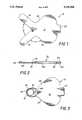
- FIG. 1is a top plan view of a cannula holding device constructed in accordance with a preferred embodiment of the invention
- FIG. 2is a side elevational view of the cannula holding device of FIG. 1;
- FIG. 3is a top plan view of the holding device attached to a cannula.
- a cannula holder constructed in accordance with a preferred embodiment of the inventionis generally denoted as element 10.
- the cannula holder 10is composed of a body region 12 and two finger like extensions 14 and 16.
- Body 12has a generally elliptical shaped central portion with an integral tab 20 disposed opposite the finger projections 14 and 16.
- the two finger extensions 14 and 16which are integrally formed with the body 12 form a generally V shaped recess between the inner edges of the fingers 14 and 16.
- An angle ⁇is formed between the inner edges of the two fingers 14 and 16. In a preferred embodiment, the angle ⁇ is in the range of 75°-85° and preferably is 80°.
- the outer edges 24 and 26 of base 12taper to merge with the outer edges of fingers 14 and 16.
- An angle ois formed between the edges 24 and 26 and the outer edges of the fingers 14 and 16.
- the angle ⁇is in the range of 80° to 95° and preferably is 90°.
- the body portion 12, tab 20 and fingers 14 and 16 of cannula holder 10is a single integral piece.
- the shape of body 12is designed to maximize the surface area that comes into contact with a patient's skin.
- the cannula holder 10is constructed of several layers as may be seen in FIG. 2.
- the layer 32is formed of a porous, hypoallergenic, material such as gauze or any other breathable sheet material known in the art. This layer has an approximate thickness of 0.015.
- An adhesive layer 34is attached to layer 32. In a preferred embodiment, the adhesive layer is an integral part of the gauze layer 32. In an alternate embodiment, layers 32 and 34 are distinctly separate layers.
- Layer 36is composed of a plurality of distinct parts. For the ease of illustration only three parts are shown and are labeled 36a, 36b, and 36c. Part 36a covers tab 20, part 36b covers body 12 and part 36c covers fingers 14 and 16.
- Layer 36is composed of a paper backing with the side facing layer 34 covered with a coating, such as wax, to reduce the transfer of adhesive from layer 34 and allow for easy separation of the layers 34 and 36.
- Layer 36is divided into a regions 36a, 36b and 36c by breaks 38 that extend through region 36. These breaks 38 permits separation of individual parts of layer 36 to expose the adhesive layer 34 below.
- the cannula guard 10may be positioned on a patient's body without exposing the adhesive layer 34 located below the gauze layer 32 of the finger regions 14 and 16.
- tab 20may be either secured to the patient's skin or the layer 36a may be left in place to provide a tab for removing the cannula holder from the skin.
- FIG. 3illustrates the holder 10 in use.
- a cannula 40is inserted into an incision made by a trocar. Regions 36a and 36b of layer 36 are removed so that adhesive layer 34 is exposed. Medical personnel then position the holder 10 in proximity to the cannula 40 and secure the exposed portion of adhesive layer 34 to the patient's skin. Then region 36c is removed to expose the remainder of adhesive layer 34. Finger 16 is wrapped around one side of cannula 40 so that the adhesive layer 34 comes into binding contact with the outer surface of the cannula 40. Finger 14 is then wrapped around the other side of the cannula 40 so that adhesive layer 34 makes binding contact with the outer surface of the cannula.
- the fingers 14 and 16are long enough to entirely engage the outer surface of the cannula 40 and to overlap as shown at 42. In an alternate embodiment, the fingers 14 and 16 do not overlap.
- a fold line 44is formed in layers 32 and 34. This fold line allows for the cannula to be easily adjusted with respect to the incision.
- the use of adhesive to attach the cannula holder to the skindoes not traumatize the adjacent skin. This device has the additional advantages of being non-invasive and also providing for fast, easy application. Additionally, the cost associated with the device is significantly less than the prior art alternatives.
Landscapes
- Health & Medical Sciences (AREA)
- Life Sciences & Earth Sciences (AREA)
- Biophysics (AREA)
- Pulmonology (AREA)
- Engineering & Computer Science (AREA)
- Anesthesiology (AREA)
- Biomedical Technology (AREA)
- Heart & Thoracic Surgery (AREA)
- Hematology (AREA)
- Animal Behavior & Ethology (AREA)
- General Health & Medical Sciences (AREA)
- Public Health (AREA)
- Veterinary Medicine (AREA)
- Media Introduction/Drainage Providing Device (AREA)
Abstract
Description
Claims (11)
Priority Applications (1)
| Application Number | Priority Date | Filing Date | Title |
|---|---|---|---|
| US07/712,738US5135506A (en) | 1991-06-10 | 1991-06-10 | Cannula holding device |
Applications Claiming Priority (1)
| Application Number | Priority Date | Filing Date | Title |
|---|---|---|---|
| US07/712,738US5135506A (en) | 1991-06-10 | 1991-06-10 | Cannula holding device |
Publications (1)
| Publication Number | Publication Date |
|---|---|
| US5135506Atrue US5135506A (en) | 1992-08-04 |
Family
ID=24863354
Family Applications (1)
| Application Number | Title | Priority Date | Filing Date |
|---|---|---|---|
| US07/712,738Expired - Fee RelatedUS5135506A (en) | 1991-06-10 | 1991-06-10 | Cannula holding device |
Country Status (1)
| Country | Link |
|---|---|
| US (1) | US5135506A (en) |
Cited By (52)
| Publication number | Priority date | Publication date | Assignee | Title |
|---|---|---|---|---|
| US5221265A (en)* | 1991-03-27 | 1993-06-22 | Lohmann Gmbh & Co. Kg | Attachment patch |
| US5336206A (en)* | 1989-08-15 | 1994-08-09 | United States Surgical Corporation | Trocar penetration depth indicator and guide tube positioning device |
| US5370625A (en)* | 1989-08-15 | 1994-12-06 | United States Surgical Corporation | Trocar guide tube positioning device |
| US5448985A (en)* | 1994-10-25 | 1995-09-12 | Byrd; Timothy N. | Endotracheal tube holding device and associated tube holding method |
| US5513635A (en)* | 1995-02-02 | 1996-05-07 | Bedi; Shan | Nasal cannula anchoring apparatus |
| USD375355S (en) | 1995-03-14 | 1996-11-05 | Venetec International, Inc. | Anchor pad with release layer |
| USD375356S (en) | 1995-04-27 | 1996-11-05 | Venetec International, Inc. | Anchor pad with release layer |
| US5638814A (en)* | 1994-10-25 | 1997-06-17 | Byrd; Timothy N. | Endotracheal tube holding device and associated tube holding method |
| US5653228A (en)* | 1994-10-25 | 1997-08-05 | Byrd; Timothy N. | Medical tube holding device and associated securing strap |
| US5682881A (en)* | 1996-10-21 | 1997-11-04 | Winthrop; Neil | Nasal CPAP/Cannula and securement apparatus |
| EP0807450A1 (en)* | 1996-05-18 | 1997-11-19 | Anthony Damien Redmond | Surgical devices |
| US5702371A (en)* | 1989-07-24 | 1997-12-30 | Venetec International, Inc. | Tube fitting anchoring system |
| USD389911S (en) | 1996-07-26 | 1998-01-27 | Venetec International, Inc. | Anchor pad |
| USD393903S (en) | 1995-08-24 | 1998-04-28 | Venetec International, Inc. | Anchor pad |
| US5800402A (en)* | 1993-03-19 | 1998-09-01 | Venetec International, Inc. | Catheter anchoring system and method of use |
| US5827230A (en)* | 1989-07-24 | 1998-10-27 | Venetec International, Inc. | Catheter anchoring system |
| US5833663A (en)* | 1997-01-27 | 1998-11-10 | Bierman; Steven F. | Naso-gastric tube retainer |
| US5833667A (en)* | 1993-03-19 | 1998-11-10 | Venetec International, Inc. | Catheter anchoring system |
| USD401329S (en) | 1996-07-24 | 1998-11-17 | Venetec International, Inc. | Anchor pad |
| USD404815S (en)* | 1997-10-20 | 1999-01-26 | Venetec International, Inc. | Anchor pad |
| US5868742A (en)* | 1995-10-18 | 1999-02-09 | Conmed Corporation | Auxiliary reference electrode and potential referencing technique for endoscopic electrosurgical instruments |
| USD405527S (en) | 1997-08-14 | 1999-02-09 | Susan Uske | Top surface of a tube securing device |
| US5964734A (en)* | 1997-12-09 | 1999-10-12 | Peeno; Barbara M. | Self adhesive catheter tube |
| US6047699A (en)* | 1998-10-23 | 2000-04-11 | The Ryatt Corporation | Ventilator and trach holder device |
| US6290676B1 (en) | 1989-07-24 | 2001-09-18 | Venetec International, Inc. | Catheter anchoring system |
| US6328038B1 (en) | 1998-07-14 | 2001-12-11 | Fred Bruce Kessler | Nasal cannula retainer |
| US20020099360A1 (en)* | 2001-01-22 | 2002-07-25 | Bierman Steven F. | Medical device connector fitting |
| US20020133121A1 (en)* | 1993-03-19 | 2002-09-19 | Bierman Steven F. | Catheter anchoring system |
| US20020157673A1 (en)* | 1998-07-14 | 2002-10-31 | Kessler Fred B. | Nasal cannula retainer |
| US6786892B2 (en) | 1993-03-19 | 2004-09-07 | Venetec International, Inc. | Catheter anchoring system |
| US6837875B1 (en) | 1993-03-19 | 2005-01-04 | Venetec International, Inc. | Catheter anchoring system |
| US20050013957A1 (en)* | 2003-07-15 | 2005-01-20 | Boris Leschinsky | Disposable medical article with multiple adhesives for skin attachment |
| USD503977S1 (en) | 2004-01-23 | 2005-04-12 | Venetec International, Inc. | Anchor pad |
| WO2005025664A3 (en)* | 2003-09-08 | 2005-07-21 | Dale Med Prod Inc | Medical tube holder with angled tabs |
| US7267124B1 (en) | 2006-02-07 | 2007-09-11 | Roberson Jr Travis Hubert | Emergency tracheostomy kit |
| US20080300546A1 (en)* | 2006-03-22 | 2008-12-04 | Baylis Medical Company Inc. | Devices and methods for stabilizing medical instruments |
| US20090292256A1 (en)* | 2008-05-22 | 2009-11-26 | Ed Cubberly | Nasogastric tube fastener |
| US20100179481A1 (en)* | 2007-09-10 | 2010-07-15 | Venetec International, Inc. | Securement device for a neonate |
| US20100199997A1 (en)* | 2009-02-10 | 2010-08-12 | Mcinnes John Gordon | Tracheal tube support apparatus |
| US20100292649A1 (en)* | 2009-05-18 | 2010-11-18 | Morrison David A | Device for securing medical tubing |
| US8052649B2 (en) | 2005-09-19 | 2011-11-08 | Venetec International, Inc. | Medical tubing securement assembly and methods of use |
| US20120167894A1 (en)* | 2010-12-31 | 2012-07-05 | O2Ool, Llc | Apparatus for positioning a nasal cannula |
| US8585655B2 (en) | 2005-05-23 | 2013-11-19 | Venetec International, Inc. | Securement device for I.V. t-connector |
| US8608705B2 (en) | 2009-03-04 | 2013-12-17 | C.R. Bard, Inc. | Catheter securement device |
| US9604034B2 (en) | 2011-04-21 | 2017-03-28 | C. R. Bard, Inc. | Anchoring system |
| US9694130B2 (en) | 2009-10-06 | 2017-07-04 | Venetec International, Inc. | Stabilizing device having a snap clamp |
| US9700700B2 (en) | 2010-03-03 | 2017-07-11 | Venetec International, Inc. | Medical article with rotatable wings |
| US9731097B2 (en) | 2009-10-06 | 2017-08-15 | Venetec International, Inc. | Stabilizing device having a locking collet |
| US9962524B2 (en) | 2011-03-11 | 2018-05-08 | Venetec International, Inc. | Medical article securement device |
| US9993619B2 (en) | 2007-07-17 | 2018-06-12 | C. R. Bard, Inc. | Securement system for a medical article |
| US20200078561A1 (en)* | 2015-08-21 | 2020-03-12 | 3M Innovative Properties Company | Nasogastric Tube Securement Systems and Methods of Using Same |
| USD980420S1 (en)* | 2019-08-01 | 2023-03-07 | Catheter Precision, Inc. | Kit of positioning patches |
Citations (3)
| Publication number | Priority date | Publication date | Assignee | Title |
|---|---|---|---|---|
| US4324237A (en)* | 1980-02-26 | 1982-04-13 | E-Med Corporation | Intravenous catheter and tubing securement and dressing device with a window over the puncture or wound site |
| US4490141A (en)* | 1982-08-04 | 1984-12-25 | Becton Dickinson And Company | Catheter stabilizer and method of securing same to a patient |
| US4534762A (en)* | 1982-12-27 | 1985-08-13 | Heyer Hal B | Vascular puncture dressing |
- 1991
- 1991-06-10USUS07/712,738patent/US5135506A/ennot_activeExpired - Fee Related
Patent Citations (3)
| Publication number | Priority date | Publication date | Assignee | Title |
|---|---|---|---|---|
| US4324237A (en)* | 1980-02-26 | 1982-04-13 | E-Med Corporation | Intravenous catheter and tubing securement and dressing device with a window over the puncture or wound site |
| US4490141A (en)* | 1982-08-04 | 1984-12-25 | Becton Dickinson And Company | Catheter stabilizer and method of securing same to a patient |
| US4534762A (en)* | 1982-12-27 | 1985-08-13 | Heyer Hal B | Vascular puncture dressing |
Cited By (72)
| Publication number | Priority date | Publication date | Assignee | Title |
|---|---|---|---|---|
| US6290676B1 (en) | 1989-07-24 | 2001-09-18 | Venetec International, Inc. | Catheter anchoring system |
| US5827230A (en)* | 1989-07-24 | 1998-10-27 | Venetec International, Inc. | Catheter anchoring system |
| US5702371A (en)* | 1989-07-24 | 1997-12-30 | Venetec International, Inc. | Tube fitting anchoring system |
| US5336206A (en)* | 1989-08-15 | 1994-08-09 | United States Surgical Corporation | Trocar penetration depth indicator and guide tube positioning device |
| US5370625A (en)* | 1989-08-15 | 1994-12-06 | United States Surgical Corporation | Trocar guide tube positioning device |
| US5221265A (en)* | 1991-03-27 | 1993-06-22 | Lohmann Gmbh & Co. Kg | Attachment patch |
| US7967792B2 (en) | 1993-03-19 | 2011-06-28 | Venetec International, Inc. | Catheter anchoring system |
| US6837875B1 (en) | 1993-03-19 | 2005-01-04 | Venetec International, Inc. | Catheter anchoring system |
| US6786892B2 (en) | 1993-03-19 | 2004-09-07 | Venetec International, Inc. | Catheter anchoring system |
| US7887515B2 (en) | 1993-03-19 | 2011-02-15 | Venetec International, Inc. | Catheter anchoring system |
| US6827705B2 (en) | 1993-03-19 | 2004-12-07 | Venetec International, Inc. | Catheter anchoring system |
| US5833667A (en)* | 1993-03-19 | 1998-11-10 | Venetec International, Inc. | Catheter anchoring system |
| US7744572B2 (en) | 1993-03-19 | 2010-06-29 | Venetec International, Inc. | Catheter anchoring system |
| US20020133121A1 (en)* | 1993-03-19 | 2002-09-19 | Bierman Steven F. | Catheter anchoring system |
| US5800402A (en)* | 1993-03-19 | 1998-09-01 | Venetec International, Inc. | Catheter anchoring system and method of use |
| US5448985A (en)* | 1994-10-25 | 1995-09-12 | Byrd; Timothy N. | Endotracheal tube holding device and associated tube holding method |
| US5638814A (en)* | 1994-10-25 | 1997-06-17 | Byrd; Timothy N. | Endotracheal tube holding device and associated tube holding method |
| US5653228A (en)* | 1994-10-25 | 1997-08-05 | Byrd; Timothy N. | Medical tube holding device and associated securing strap |
| US5513635A (en)* | 1995-02-02 | 1996-05-07 | Bedi; Shan | Nasal cannula anchoring apparatus |
| USD375355S (en) | 1995-03-14 | 1996-11-05 | Venetec International, Inc. | Anchor pad with release layer |
| USD375356S (en) | 1995-04-27 | 1996-11-05 | Venetec International, Inc. | Anchor pad with release layer |
| USD393903S (en) | 1995-08-24 | 1998-04-28 | Venetec International, Inc. | Anchor pad |
| US5868742A (en)* | 1995-10-18 | 1999-02-09 | Conmed Corporation | Auxiliary reference electrode and potential referencing technique for endoscopic electrosurgical instruments |
| EP0807450A1 (en)* | 1996-05-18 | 1997-11-19 | Anthony Damien Redmond | Surgical devices |
| GB2313315B (en)* | 1996-05-18 | 2000-01-19 | Anthony Damien Redmond | Surgical devices |
| USD401329S (en) | 1996-07-24 | 1998-11-17 | Venetec International, Inc. | Anchor pad |
| USD389911S (en) | 1996-07-26 | 1998-01-27 | Venetec International, Inc. | Anchor pad |
| US5682881A (en)* | 1996-10-21 | 1997-11-04 | Winthrop; Neil | Nasal CPAP/Cannula and securement apparatus |
| US5833663A (en)* | 1997-01-27 | 1998-11-10 | Bierman; Steven F. | Naso-gastric tube retainer |
| USD405527S (en) | 1997-08-14 | 1999-02-09 | Susan Uske | Top surface of a tube securing device |
| USD404815S (en)* | 1997-10-20 | 1999-01-26 | Venetec International, Inc. | Anchor pad |
| US5964734A (en)* | 1997-12-09 | 1999-10-12 | Peeno; Barbara M. | Self adhesive catheter tube |
| US20020157673A1 (en)* | 1998-07-14 | 2002-10-31 | Kessler Fred B. | Nasal cannula retainer |
| US6328038B1 (en) | 1998-07-14 | 2001-12-11 | Fred Bruce Kessler | Nasal cannula retainer |
| US6047699A (en)* | 1998-10-23 | 2000-04-11 | The Ryatt Corporation | Ventilator and trach holder device |
| US20020099360A1 (en)* | 2001-01-22 | 2002-07-25 | Bierman Steven F. | Medical device connector fitting |
| US8043280B2 (en) | 2001-01-22 | 2011-10-25 | Venetec International, Inc. | Medical device connector fitting |
| US7316679B2 (en) | 2001-01-22 | 2008-01-08 | Venetec International, Inc. | Medical device connector fitting |
| US20080077118A1 (en)* | 2001-01-22 | 2008-03-27 | Venetec International, Inc. | Medical device connector fitting |
| US20050013957A1 (en)* | 2003-07-15 | 2005-01-20 | Boris Leschinsky | Disposable medical article with multiple adhesives for skin attachment |
| US20110208103A1 (en)* | 2003-07-15 | 2011-08-25 | Boris Leschinsky | Disposable medical article with multiple adhesives for skin attachment |
| WO2005025664A3 (en)* | 2003-09-08 | 2005-07-21 | Dale Med Prod Inc | Medical tube holder with angled tabs |
| USD503977S1 (en) | 2004-01-23 | 2005-04-12 | Venetec International, Inc. | Anchor pad |
| US8585655B2 (en) | 2005-05-23 | 2013-11-19 | Venetec International, Inc. | Securement device for I.V. t-connector |
| US8052649B2 (en) | 2005-09-19 | 2011-11-08 | Venetec International, Inc. | Medical tubing securement assembly and methods of use |
| US8177756B2 (en) | 2005-09-19 | 2012-05-15 | Venetec International, Inc. | Medical tubing securement assembly and methods of use |
| US8679067B2 (en) | 2005-09-19 | 2014-03-25 | Venetec International, Inc. | Medical tubing securement assembly and methods of use |
| US7267124B1 (en) | 2006-02-07 | 2007-09-11 | Roberson Jr Travis Hubert | Emergency tracheostomy kit |
| US20080300546A1 (en)* | 2006-03-22 | 2008-12-04 | Baylis Medical Company Inc. | Devices and methods for stabilizing medical instruments |
| US9993619B2 (en) | 2007-07-17 | 2018-06-12 | C. R. Bard, Inc. | Securement system for a medical article |
| US20100179481A1 (en)* | 2007-09-10 | 2010-07-15 | Venetec International, Inc. | Securement device for a neonate |
| US20090292256A1 (en)* | 2008-05-22 | 2009-11-26 | Ed Cubberly | Nasogastric tube fastener |
| US20100199997A1 (en)* | 2009-02-10 | 2010-08-12 | Mcinnes John Gordon | Tracheal tube support apparatus |
| US8230862B2 (en) | 2009-02-10 | 2012-07-31 | Mcinnes John Gordon | Tracheal tube support apparatus |
| US8608705B2 (en) | 2009-03-04 | 2013-12-17 | C.R. Bard, Inc. | Catheter securement device |
| US9017290B2 (en) | 2009-03-04 | 2015-04-28 | C. R. Bard. Inc. | Catheter securement device |
| US8317755B2 (en)* | 2009-05-18 | 2012-11-27 | Morrison David A | Device for securing medical tubing |
| US20100292649A1 (en)* | 2009-05-18 | 2010-11-18 | Morrison David A | Device for securing medical tubing |
| US10426928B2 (en) | 2009-10-06 | 2019-10-01 | Venetec International, Inc. | Stabilizing device having a snap clamp |
| US12171959B2 (en) | 2009-10-06 | 2024-12-24 | Venetec International, Inc. | Stabilizing device having a snap clamp |
| US9694130B2 (en) | 2009-10-06 | 2017-07-04 | Venetec International, Inc. | Stabilizing device having a snap clamp |
| US9731097B2 (en) | 2009-10-06 | 2017-08-15 | Venetec International, Inc. | Stabilizing device having a locking collet |
| US11420023B2 (en) | 2009-10-06 | 2022-08-23 | Venetec International, Inc. | Stabilizing device having a snap clamp |
| US10245415B2 (en) | 2010-03-03 | 2019-04-02 | Venetec International, Inc. | Medical article with rotatable wings |
| US9700700B2 (en) | 2010-03-03 | 2017-07-11 | Venetec International, Inc. | Medical article with rotatable wings |
| US20120167894A1 (en)* | 2010-12-31 | 2012-07-05 | O2Ool, Llc | Apparatus for positioning a nasal cannula |
| US9205216B2 (en)* | 2010-12-31 | 2015-12-08 | 0200L, Llc | Apparatus for positioning a nasal cannula |
| CN103402570A (en)* | 2010-12-31 | 2013-11-20 | O2Ool有限责任公司 | Apparatus for positioning a nasal cannula |
| US9962524B2 (en) | 2011-03-11 | 2018-05-08 | Venetec International, Inc. | Medical article securement device |
| US9604034B2 (en) | 2011-04-21 | 2017-03-28 | C. R. Bard, Inc. | Anchoring system |
| US20200078561A1 (en)* | 2015-08-21 | 2020-03-12 | 3M Innovative Properties Company | Nasogastric Tube Securement Systems and Methods of Using Same |
| USD980420S1 (en)* | 2019-08-01 | 2023-03-07 | Catheter Precision, Inc. | Kit of positioning patches |
Similar Documents
| Publication | Publication Date | Title |
|---|---|---|
| US5135506A (en) | Cannula holding device | |
| US6105579A (en) | Ophthalmic drape with tear line and method | |
| US5351680A (en) | Surgical retractor | |
| CN100500103C (en) | Surgical treatment instrument | |
| US5713839A (en) | Pre-operative nasal splint for endoscopic sinus surgery | |
| US4870977A (en) | Surgical protector for raised wounds | |
| EP1237499B1 (en) | Bandage for wound or incision closure | |
| JP4181306B2 (en) | Wound retractor device | |
| US6015119A (en) | Combination holding and stabilizing device | |
| US6283126B1 (en) | Hand shield | |
| US20080319261A1 (en) | Cannula device for endoscopic surgical operations | |
| US5709646A (en) | Surgical retractor covers | |
| US6286511B1 (en) | Ophthalmic drape with tear line and method | |
| US20110040258A1 (en) | Flexible and adjustable wrap for protecting and stabilizing intravenous catheter | |
| US6647985B1 (en) | Barrier surgical drape for speculums or retractors | |
| ES2245794T3 (en) | TRANSNASAL DUCT. | |
| JP2002325769A (en) | Tool for medical treatment | |
| JP2022520441A (en) | Flexible trocar for advancing wound drain catheter through tissue with blunt tip and connector | |
| JPH0714419B2 (en) | Drain holding device | |
| US20030028148A1 (en) | Tubing holder and stabilizer | |
| US11612535B2 (en) | Surgery pillow and device combining endotracheal tube holder, bite guard, and patient eye protector | |
| US20210379315A1 (en) | Airway and Eye Taping System and Method of Its Use | |
| JP2006272018A (en) | Medical treatment instrument | |
| EP1047469B1 (en) | A device for the fixation of a tube member | |
| EP4257100B1 (en) | A medical dressing for use in conjunction with a trocar |
Legal Events
| Date | Code | Title | Description |
|---|---|---|---|
| AS | Assignment | Owner name:CONMED CORPORATION, NEW YORK Free format text:ASSIGNMENT OF ASSIGNORS INTEREST.;ASSIGNORS:GENTELIA, JOHN;CALENZO, JAMES C., SR.;WILLIAMS, FRANK;REEL/FRAME:005740/0348 Effective date:19910606 | |
| FEPP | Fee payment procedure | Free format text:PAYOR NUMBER ASSIGNED (ORIGINAL EVENT CODE: ASPN); ENTITY STATUS OF PATENT OWNER: LARGE ENTITY | |
| FEPP | Fee payment procedure | Free format text:PAT HLDR NO LONGER CLAIMS SMALL ENT STAT AS SMALL BUSINESS (ORIGINAL EVENT CODE: LSM2); ENTITY STATUS OF PATENT OWNER: LARGE ENTITY | |
| FPAY | Fee payment | Year of fee payment:4 | |
| AS | Assignment | Owner name:CHASE MANHATTAN BANK, AS ADMINISTRATIVE AGENT, THE Free format text:SECURITY INTEREST;ASSIGNORS:CONMED CORPORATION (NY CORPORATION);ASPEN LABORATORIES, INC. (CO CORPORATION);CONMED ANDOVER MEDICAL, INC. (NY CORPORATION);AND OTHERS;REEL/FRAME:009187/0010 Effective date:19971231 | |
| REMI | Maintenance fee reminder mailed | ||
| LAPS | Lapse for failure to pay maintenance fees | ||
| FP | Lapsed due to failure to pay maintenance fee | Effective date:20000804 | |
| STCH | Information on status: patent discontinuation | Free format text:PATENT EXPIRED DUE TO NONPAYMENT OF MAINTENANCE FEES UNDER 37 CFR 1.362 |