US5135500A - Self-driven pump device - Google Patents
Self-driven pump deviceDownload PDFInfo
- Publication number
- US5135500A US5135500AUS07/429,412US42941289AUS5135500AUS 5135500 AUS5135500 AUS 5135500AUS 42941289 AUS42941289 AUS 42941289AUS 5135500 AUS5135500 AUS 5135500A
- Authority
- US
- United States
- Prior art keywords
- chamber
- fluid
- plunger
- orifice
- head
- Prior art date
- Legal status (The legal status is an assumption and is not a legal conclusion. Google has not performed a legal analysis and makes no representation as to the accuracy of the status listed.)
- Expired - Lifetime
Links
- 239000012530fluidSubstances0.000claimsabstractdescription242
- 238000003860storageMethods0.000claimsabstractdescription121
- 238000004891communicationMethods0.000claimsabstractdescription14
- 230000000694effectsEffects0.000claimsabstractdescription7
- 238000007789sealingMethods0.000claimsdescription17
- 241000272525Anas platyrhynchosSpecies0.000claimsdescription10
- 239000007788liquidSubstances0.000description11
- 238000001990intravenous administrationMethods0.000description10
- 239000013543active substanceSubstances0.000description6
- 238000001802infusionMethods0.000description6
- 230000007246mechanismEffects0.000description4
- 230000005540biological transmissionEffects0.000description3
- 238000002347injectionMethods0.000description3
- 239000007924injectionSubstances0.000description3
- 238000000034methodMethods0.000description3
- 230000002035prolonged effectEffects0.000description3
- 238000013461designMethods0.000description2
- 239000003814drugSubstances0.000description2
- 229940079593drugDrugs0.000description2
- 239000007789gasSubstances0.000description2
- 239000000463materialSubstances0.000description2
- 239000004033plasticSubstances0.000description2
- 230000004913activationEffects0.000description1
- 230000002411adverseEffects0.000description1
- 239000002246antineoplastic agentSubstances0.000description1
- 230000008901benefitEffects0.000description1
- 239000013060biological fluidSubstances0.000description1
- 239000008280bloodSubstances0.000description1
- 210000004369bloodAnatomy0.000description1
- 229940044683chemotherapy drugDrugs0.000description1
- 230000008878couplingEffects0.000description1
- 238000010168coupling processMethods0.000description1
- 238000005859coupling reactionMethods0.000description1
- 239000013536elastomeric materialSubstances0.000description1
- 231100001261hazardousToxicity0.000description1
- 238000003780insertionMethods0.000description1
- 230000037431insertionEffects0.000description1
- 230000003993interactionEffects0.000description1
- 238000004519manufacturing processMethods0.000description1
- 230000013011matingEffects0.000description1
- 238000007911parenteral administrationMethods0.000description1
- 230000000704physical effectEffects0.000description1
- 230000009467reductionEffects0.000description1
- 239000000243solutionSubstances0.000description1
- 239000000126substanceSubstances0.000description1
- 238000003466weldingMethods0.000description1
Images


Classifications
- A—HUMAN NECESSITIES
- A61—MEDICAL OR VETERINARY SCIENCE; HYGIENE
- A61M—DEVICES FOR INTRODUCING MEDIA INTO, OR ONTO, THE BODY; DEVICES FOR TRANSDUCING BODY MEDIA OR FOR TAKING MEDIA FROM THE BODY; DEVICES FOR PRODUCING OR ENDING SLEEP OR STUPOR
- A61M5/00—Devices for bringing media into the body in a subcutaneous, intra-vascular or intramuscular way; Accessories therefor, e.g. filling or cleaning devices, arm-rests
- A61M5/14—Infusion devices, e.g. infusing by gravity; Blood infusion; Accessories therefor
- A61M5/142—Pressure infusion, e.g. using pumps
- A61M5/145—Pressure infusion, e.g. using pumps using pressurised reservoirs, e.g. pressurised by means of pistons
- A61M5/1452—Pressure infusion, e.g. using pumps using pressurised reservoirs, e.g. pressurised by means of pistons pressurised by means of pistons
- A61M5/14526—Pressure infusion, e.g. using pumps using pressurised reservoirs, e.g. pressurised by means of pistons pressurised by means of pistons the piston being actuated by fluid pressure
- A—HUMAN NECESSITIES
- A61—MEDICAL OR VETERINARY SCIENCE; HYGIENE
- A61M—DEVICES FOR INTRODUCING MEDIA INTO, OR ONTO, THE BODY; DEVICES FOR TRANSDUCING BODY MEDIA OR FOR TAKING MEDIA FROM THE BODY; DEVICES FOR PRODUCING OR ENDING SLEEP OR STUPOR
- A61M5/00—Devices for bringing media into the body in a subcutaneous, intra-vascular or intramuscular way; Accessories therefor, e.g. filling or cleaning devices, arm-rests
- A61M5/14—Infusion devices, e.g. infusing by gravity; Blood infusion; Accessories therefor
- A61M5/142—Pressure infusion, e.g. using pumps
- A61M5/145—Pressure infusion, e.g. using pumps using pressurised reservoirs, e.g. pressurised by means of pistons
- A61M2005/14513—Pressure infusion, e.g. using pumps using pressurised reservoirs, e.g. pressurised by means of pistons with secondary fluid driving or regulating the infusion
Definitions
- This inventionrelates to an apparatus and method for delivering fluid with a controlled rate of flow. More particularly this invention relates to a simple, compact, inexpensive infuser which is capable of delivering a relatively constant dosage of an active agent at a controlled rate for parenteral delivery, and to a method for achieving such delivery of fluid.
- Active agentsare commonly administered to a subject parenterally either by injection or infusion.
- an injectionintroduces a dosage of drug in a pulse form, either subcutaneously, intramuscularly, intravenously, or intraarterially, whereas an infusion introduces the active agent in a continuous manner over a prolonged period of time, such as, for example, in the conventional intravenous drip.
- pulse dosagesin which a relatively large amount of the active agent is rapidly deposited for consumption in the body over a prolonged period of time, in favor of the administration over long periods of time of smaller doses.
- An intravenous infusion setcomprises a bottle for the fluid which is supported in an inverted position at a higher level than the patient, an intravenous feed tube, typically of a plastic material and a resistor mechanism, such as a clamp operating on the plastic tube, the clamp being adjusted so as to allow the fluid to drip at a controlled rate into a drip chamber located below the bottle.
- the drip chamberallows a nurse or other attendant to observe the rate of flow of fluid from the bottle and to adjust the resistor to give a desired rate.
- an intravenous infusion sethas several virtues, including simplicity, independence from external power supplies and adjustability over a wide range of flow rates, it is not entirely satisfactory because it is subject to variations in the flow rate produced. It is therefore necessary that the flow rate of the fluids delivered by the intravenous set be monitored frequently and adjusted as necessary to maintain the desired rate.
- the physical properties and dimensions of the elastomeric balloonmust be carefully controlled by provide the desired controlled flow rate. Changes in rubber durometer or tube wall thickness can materially affect fluid delivery rate. Further, the delivery rate may be adversely affected by variations in pressure on the elastomeric balloon resulting from changes in external pressure such as atmospheric pressure. Also, the elastomeric balloon may burst in actual use if not properly formulated, and this can be extremely hazardous, particularly in the case of chemotherapeutic drugs and the like. Additionally, the elastomeric balloon is not readily adapted to factory pre-filling and extended storage, particularly of medicinal fluids, because of chemical interaction between the elastomeric balloon and the fluid.
- the apparatusincludes an "actuator" which includes a vacuum power unit.
- the vacuum power unitincludes a cylinder which is closed at one end and has a piston slidable therein.
- the piston in the cylinder of the vacuum power unitis coupled to a movable wall of a liquid storage container through a cross-head 15 which functions as a transmission mechanically coupling the separate piston of the liquid storage container to the piston in the cylinder of the vacuum power unit.
- the cylinder of the vacuum power unitis evacuated when the slidable piston is substantially at the open end of the cylinder so that atmospheric pressure acts upon the piston to drive it towards the closed end of the cylinder.
- That motionproduces a reduction of the volume of the liquid storage container through the cross-head transmission which couples the piston in the vacuum cylinder to the movable wall of the container.
- This apparatusis rather cumbersome and complicated.
- the vacuum power unit and liquid storage unitare configured parallel to one another, and the apparatus relies on a two piston arrangement in combination with the transmission means connecting the two separate pistons to effect delivery of the liquid from the storage container.
- the apparatusdoes not provide a single plunger means to provide the power drive means and to effect discharge of the liquid from the apparatus.
- a related objectis to provide such a device that is portable and not cumbersome and is thus suitable for use by ambulatory patients.
- the present inventionprovides a vacuum powered apparatus for delivering fluid with a relatively constant, controlled rate of flow.
- vacuum power or vacuum poweredmeans the driving force on a movable wall caused by a differential in pressure between atmospheric pressure on one side of the movable wall and a second pressure, which is less than atmospheric pressure, on the other side of the movable wall.
- the apparatus of the present inventionincludes a vacuum power means for driving a fluid to be delivered from the apparatus, a fluid storage means carried in axial alignment with the vacuum power means and adapted to carry fluid to be delivered by the apparatus, and a plunger means carried by the vacuum power means in axial communication with the fluid storage means.
- the vacuum power meansis open to the atmosphere at one end, and at the other end is sealed from the atmosphere.
- the vacuum power meansincludes a sealed portion which comprises at least a partial vacuum.
- the plunger meansforms a movable wall which sealingly and slidingly engages the sealed portion of the vacuum power means and is disposed in the vacuum power means so that the movable wall forms an end wall of the sealed portion of the vacuum power means.
- the sealed portion of the vacuum power meansis at least partially evacuated when the plunger means is substantially at the open end of the vacuum power means, and atmospheric pressure acts upon the plunger means to drive it towards the sealed end of the vacuum means.
- atmospheric pressure acting on the plunger meansdrives the movable wall of the plunger means toward the sealed end of the vacuum power means and directly drives the plunger means toward the orifice of the fluid storage means to thereby drive the fluid contained in the fluid storage means through the orifice to deliver the fluid from the apparatus.
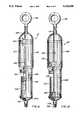
- FIG. 1is a perspective view of the vacuum powered fluid delivery apparatus of the present invention with a partial cut-away view of the interior of the vacuum power means and the fluid storage means showing the axial alignment thereof and the plunger means axially aligned in both the vacuum power means and the fluid storage means.
- FIG. 2is a sectional view of the apparatus taken along line 2--2 of FIG. 1 and showing the vacuum power means and the fluid storage means detached from one another and ready for assembly.
- FIG. 3is a sectional view of the apparatus taken along line 3--3 of FIG. 1 and showing the vacuum power means and the fluid storage means detachably secured to one another with the plunger means located at the open end of the vacuum power means and in the activated position ready to deliver fluid.
- FIG. 4is a sectional view of the apparatus taken along line 4--4 of FIG. 1 and showing the vacuum power means and the fluid storage means detachably secured to one another with the plunger means located at the sealed end of the vacuum power means and in the inactive position.
- FIGS. 5 and 6are sectional views of a valve arrangement and an unlocking mechanism for the orifice of the fluid storage means.
- FIG. 5shows the valve in the closed position and the unlocking mechanism partially inserted and in sealing engagement with the valve.
- FIG. 6shows the unlocking mechanism fully inserted into the valve and the valve in the open position.
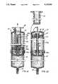
- FIG. 7is a perspective view of an alternative embodiment of the vacuum powered fluid delivery apparatus of the present invention with a partial cut-away view of the interior of the vacuum power means showing the plunger in the activated position, and a fluid storage means containing the fluid to be delivered separately and ready for insertion into a receptacle of the apparatus.
- FIG. 8is a side view of the apparatus shown in FIG. 7, in section, with the plunger means in the inactive position.
- FIG. 9is a side view of the apparatus shown in FIG. 7, in section, with the plunger means in the activated position and the fluid storage means in position for delivery of fluid.
- FIG. 10is a side view of the apparatus of FIG. 7, in section, illustrating the position of the plunger means in the respective vacuum power means and fluid storage means after fluid delivery.
- FIG. 11is a side view of another alternative embodiment of the vacuum powered fluid delivery apparatus of the present invention showing a prefilled fluid storage means and the vacuum power means in the inactive position.
- a vacuum powered apparatus 10for the delivery of fluid with a relatively constant, controlled rate of flow, wherein the vacuum power means for driving fluid from the apparatus and the fluid storage means are axially aligned as is illustrated in FIG. 1.
- the vacuum powered apparatus 10includes a vacuum power drive means (or chamber) 11 and a separate fluid storage means 12 which may be mounted to the vacuum power drive means 11 by any suitable means sufficient to hold the vacuum power drive means 11 and the fluid storage means 12 together during operation of the device.
- the vacuum power drive means and fluid storage meansare detachably secured together by a bayonet mount, generally shown at 13. It will be appreciated that the vacuum power means and the fluid storage means may be permanently secured, as for example by spot welding or the like at the bayonet joint.
- the fluid storage means 12is adapted to carry the fluid to be delivered by the apparatus, and is disposed in axial alignment with the vacuum power means 11.
- the fluid storage means 12is separate from the vacuum power means 11 and is detachably connected to the vacuum power means in axial alignment with the vacuum power means.
- the separate and detachable nature of the fluid storage meansprovides the apparatus with substantial flexibility in that the same vacuum power drive means can be used repeatedly, with different fluid storage means to deliver different fluids and for different delivery conditions.
- the fluid storage meanshas two ends 18, 19. End 18 forms an orifice 20 for controlling delivery of fluid from the apparatus. The second end 19 is adapted to receive a plunger means as will be described more fully hereinafter.
- the vacuum power means 11has a plunger means 21 disposed therein in sealing and sliding engagement with the walls of the vacuum power means.
- the plunger means 21is in axial communication with both the vacuum power means 11 and the fluid storage means 12.
- the plunger meansboth receives the thrust of atmospheric pressure which acts on the plunger means at the open end 14 of the vacuum power means 11, and, in turn provides the driving means to drive fluid from the fluid storage means.
- plunger means 21includes a first head 22 which forms a movable wall in the vacuum power means 11.
- the first head 22sealingly and slidingly engages the side walls of the vacuum power means to allow at least a partial vacuum to be drawn in the portion of the vacuum power means 11 swept by the first head 22 as it is moved from the sealed end 16 toward the open end 14 of vacuum power means 11.
- Plunger means 21further includes a second head 23 and a rod means 24 for connecting first head 22 and second head 23.
- the rod means 24extends through the opening 17 in the sealed end 16 of vacuum power means 11 so that the second head 23 of plunger means 21 may communicate with the open end 19 of fluid storage means 12.
- the second head 23 of plunger means 21is preferably configured to fit sealingly and slidably into the open end 19 of fluid storage means 12.
- first head 22 of plunger means 21As first head 22 of plunger means 21 is moved from a position at or near sealed end 16 of vacuum power means 11, as shown in FIG. 4, to a position substantially at the open end 14 near the opening 15 in vacuum power means 11, as shown in FIG. 3, a portion 25 of the vacuum power means 11 between the first head 22 and sealed end 16 of the vacuum power means 11 is swept by first head 22.
- the portion 25 swept by first head 22is thus at least partially evacuated, i.e., at least a partial vacuum is formed in the sealed evacuated portion 25 of vacuum power means 11.
- the apparatusWhen first head 22 of plunger means 21 has been moved so as to form sealed evacuated portion 25, the apparatus is activated, that is, it is capable of delivering fluid.
- first head 22 of plunger means 21seat as closely as possible to the sealed end 16 of vacuum power means 11 in order to minimize the volume of air contained in the vacuum power means 11 between first head 22 and the sealed end 16 and thereby minimize the volume of air in sealed evacuated portion 25 of the vacuum power means after first head 22 has swept through the vacuum power means. Under such conditions, after the first head 22 has been moved to the activated position, the vacuum in the sealed evacuated portion 25 of vacuum power means is maximized. It will be appreciated that the degree of vacuum in sealed evacuated portion 25 is not critical to the operation of the apparatus so long as atmospheric pressure can act on first head 22 of plunger means 21 to cause the vacuum in sealed evacuated portion 25 to collapse as a result of the energy differential between atmospheric pressure on one side (A in FIG.
- first head 221) of first head 22 and the vacuum on the other side (V in FIG. 1) of first head 22 to allow the plunger means 21 to drive fluid from the apparatus at a relatively constant rate simultaneously with the collapse of the vacuum for the entire volume of fluid to be delivered from the apparatus.
- the internal gases in the sealed portion of the chamberare minimized so as to maximize the vacuum, and to thereby provide the greatest and most constant energy differential.
- first head 22 of plunger means 21When the orifice 20 of fluid storage means 12 is opened, atmospheric pressure acting upon first head 22 of plunger means 21 with thrust T will cause the vacuum in the sealed evacuated portion 25 of the vacuum power means 11 to collapse. As that vacuum collapses, first head 22 of plunger means 21 is driven toward the sealed end 16 of vacuum power means 11. As first head 22 is driven toward sealed end 16 of vacuum power means 11, rod means 24 of plunger means 21 slides through opening 17 in sealed end 16 of vacuum power means 11 to drive second head 23 toward the orifice end 18 of the fluid storage means 12 to thereby drive fluid out of the orifice 20 for delivery. As illustrated in FIG.
- fluid storage means 12includes at its open end 19 a movable end wall (not shown) in sealing and sliding engagement with the side walls of fluid storage means 12.
- the rod means 24 of plunger means 21may then terminate in a blunt end (not shown) that engages the movable end wall of fluid storage means 12.
- first head 22 of plunger means 21As atmospheric pressure acts upon the first head 22 of plunger means 21 to cause the vacuum in sealed evacuated portion 25 to collapse, first head 22 is driven toward the sealed end 16 of vacuum power means 11, and the blunt end of rod means 24 engages the movable end wall of the fluid storage means 12 to drive the movable end wall of the fluid storage means 12 toward the orifice end 18 of fluid storage means 12 to thereby deliver liquid from the apparatus.
- FIGS. 11 and 12An alternative embodiment of the apparatus described above is shown in FIGS. 11 and 12. This embodiment operates in substantially the same way as the embodiment illustrated in FIGS. 1-4. However, the apparatus in accordance with this embodiment as illustrated in FIGS. 11 and 12 may be assembled with fluid storage means prefilled with the desired medicinal liquid, and with an inactive vacuum power drive, which may be activated immediately prior to use.
- the primary difference between the embodiment of FIGS. 1-4 and the embodiment of FIGS. 11 and 12lies in the configuration of the plunger means, in the provision of a handle means to activate the apparatus, and in the fact that the fluid storage means may be prefilled.
- plunger means 21aincludes a first head 22a, a second head 23a and rod means 24a for connecting the first head 22a and second head 23a.
- the first head 22ais in sealing and sliding assembly with rod means 24a so that it may move up and down along rod means 24a.
- the first head 22aincludes means for engaging the rod means when the first head 22a is substantially at the open end 14 of the vacuum power means 11 (FIG. 12).
- Handle means 39are secured to first head 22a to permit first head 22a to be moved toward the open end 14 of the vacuum power means 11 to place plunger means 21a in the activated position (FIG. 12). As illustrated in FIGS.
- the engaging means carried by the first head 22aare resilient fingers 40 which are capable of engaging and gripping a flanged portion 24b of rod means 24a.
- the engaging means 40further include threads 41 for threadingly mating with the handle means 39.
- handle means 39is threaded to the first head 22a via threads 41.
- first head 22aalso sealingly and slidingly engages the side walls of vacuum power means 11 and forms a movable wall in vacuum power means 11 to allow at least a partial vacuum to be drawn in the portion of the vacuum power means 11 swept by first piston head 22a as it is moved up along rod means 24a from a point at or near sealed end 16 to a point at or near the open end 14 of vacuum power means 11.
- FIG. 11shows the apparatus in a prefilled, inactive condition
- FIG. 12shows the apparatus in an active condition ready to deliver fluid.
- handle means 39is moved in the direction of the open end 14 of vacuum power means 11.
- first head 22amoves from its position at or near the sealed end 16 toward the open end 14 of vacuum power means 11.
- Handle means 39, and thus first head 22amust be moved in the direction of the open end 14 of vacuum power means 11 sufficiently so that engaging means 40 grip the rod means 24a.
- atmospheric pressure acting on the side of first head 22a exposed to the opening 15will drive first head 22a toward sealed end 16.
- fluid storage means 12may form a housing for a container for holding the fluid to be delivered from the apparatus.
- the fluid container, which is carried in the housing,may have collapsible walls which will collapse under the force of the plunger means acting on the container to deliver fluid from the apparatus.
- FIGS. 11 and 12One advantage of the embodiment of the invention illustrated in FIGS. 11 and 12 is that the apparatus may be prefilled, for example, by the manufacturer, or pharmacist, with medicinal fluid and stored for the shelf life of that fluid.
- the apparatusstands ready for activation and immediate use, thereby eliminating the need for either a nurse or the patient to handle the medicinal fluid to be administered.
- the orifice 20 of fluid storage means 12 of either the embodiment illustrated in FIGS. 1-4 or in FIGS. 11 and 12includes an elastomeric duck bill valve 26 as shown in greater detail in FIGS. 5 and 6.
- the valve 26is normally closed, as shown in FIG. 5 to prevent fluid from leaking out of fluid storage means 12.
- the duck bill valve 26generally comprises an end flange portion 27, an elongated central portion 28 which terminates in a tapered end portion 29, and a lumen 30 which extends from the flange portion 27 to the tapered end portion 29.
- the tapered end portion 29provides a seal by which the valve 26 is normally closed.
- the vacuum powered apparatus of the present invention as illustrated in FIGS. 1-4may be assembled either in an inactive, unfilled form and then filled to activate it, or in an activated filled form or as described above in connection with the embodiment illustrated in FIGS. 11 and 12, it may be assembled in a prefilled, inactive condition.
- the apparatus of the present inventionmay be assembled in an activated, filled condition by first filling the fluid storage means 12 with the desired fluid, causing the open end 19 of the fluid storage means to engage the second head 23 of plunger means 21 and forcing the vacuum power means 11 and fluid storage means 12 together until they mate and are secured together with the bayonet mount 13.
- the fluid in fluid storage means 12acts against the second head 23 of plunger means 21 to bias the second head 23 toward vacuum power means 11 and thereby to drive the first head 22 toward the open end 14 of vacuum power means 11.
- the portion 25 of the vacuum power means 11 swept by the first head 22is at least partially evacuated, that is, at least a partial vacuum is formed therein.
- the apparatus of the present inventionmay be assembled in an inactive, unfilled condition by attaching fluid storage means 12 to vacuum power means 11 and subsequently filling the fluid storage means with the fluid to be delivered.
- Filling fluid storage means 12drives the second head 22 of plunger means 21 toward vacuum power means 11 and drives the first head 22 toward open end 14 of vacuum power means 11.
- the portion 25 of the power chamber 11 swept by the first head 22will be at least partially evacuated and thus forms at least a partial vacuum therein.
- fluid storage means 12is filled using a male lure opening of a conventional intravenous syringe and a fluid filled syringe.
- the male lureis attached to a female lure opening of the fluid storage means 12 in locking and sealing engagement.
- the tapered end portion 29opens to allow fluid to pass through the valve and into the fluid storage means.
- the force of the injected fluidforces the second head 23 on plunger means 21 toward vacuum power means 11 and at the same time forces the first head 22 of plunger means 21 to move toward the open end 14 of vacuum power means 11.
- the first head 22sweeps a portion of the vacuum power means 11 to create sealed evacuated portion 25 to thereby create at least a partial vacuum therein.
- the male lure and syringeare removed and the valve 26 closes. The apparatus is thus activated and in condition for delivering fluid as shown in FIG. 3.
- the fluid storage meansmay be equipped with a separate fill port through which the fluid to be delivered by the apparatus is injected to fill the fluid storage means and activate the apparatus in the same manner as described above.
- a combination male lure 31 and fluid administration setis provided for opening the duck bill valve 26 and further controlling the rate at which fluid is delivered by the apparatus.
- the male lure 31includes a threaded end portion 32 for threadingly engaging a threaded end portion of the fluid storage means 12.
- Male lure 31includes an elongated tube 33 having a portion 34 of one diameter which tapers at 35 to an elongated portion 36 having a smaller diameter than the first diameter portion 34.
- the elongated portion 36 of male lure 31has a diameter such that the elongated portion can press fit into the lumen 30- of duck bill valve 26 to form a seal between the smaller diameter portion 36 of male lure 31 and the elastomeric material of the duck bill valve 26.
- the vacuum powered apparatus 90includes a vacuum power drive means 100, a separate fluid storage means 112 for storing the fluid to be delivered by the apparatus and a receptacle 102 carried by the vacuum power drive means 100 for receiving fluid storage means 112 so that the vacuum power means 100 and fluid storage means 112 are in axial alignment.
- receptacle 102is formed as an integral extension of vacuum power means 100.
- Receptacle 102includes a cylindrical wall 103 extending from vacuum power means 100 and an end wall 104. Cylindrical wall 103 and end wall 104 define a cavity 105 for receiving fluid storage means 112.
- End wall 104 of receptacle 102includes an opening 106 for receiving the orifice end of fluid storage means 112.
- Fluid storage means 112is placed in cavity 105 of receptacle 102 to ready the apparatus for fluid delivery.
- fluid storage means 112is not limited to the illustrated embodiment.
- fluid storage means 112may have a variety of shapes and may be made of a variety of materials while still providing a vacuum powered apparatus for delivering fluid with a relatively constant controlled rate of flow.
- fluid storage means 112is a cylindrical, rigid chamber
- the fluid storage meansmay comprise a flexible container that has collapsible walls which will collapse under the force of plunger means acting on the container.
- Vacuum power means 100has a first end 114 which forms an opening 115 to expose the interior of vacuum power means 100 to atmospheric pressure, and a second end 116 which is sealed from the atmosphere.
- the sealed end 116forms an opening 117 for sealingly receiving a plunger means.
- the fluid storage means 112is adapted to carry the fluid to be delivered by the apparatus and is in axial alignment with vacuum power means 100 when placed in the cavity 105 of receptacle 102.
- fluid storage means 112is separate from vacuum power means 100. The separate nature of the fluid storage means provides the apparatus with substantial flexibility in that the same vacuum power means can be used repeatedly, with different fluid storage means to deliver different fluids and for different delivery conditions.
- Fluid storage means 112has two ends 118, 119 End 118 forms an orifice 120 for controlling the delivery of fluid from the apparatus.
- the second end 119is adapted to receive a plunger means as will be described more fully hereinafter.
- the fluid storage means 112preferably includes a movable wall 130 at the second end thereof in sealing and sliding engagement with the walls of the fluid storage means. Movable wall 130 provides, in effect, a cover for fluid storage means 112.
- the vacuum power means 100has a plunger means 121 disposed therein in sealing and sliding engagement with the walls of vacuum power means 100.
- Plunger means 121is in axial communication with both vacuum power means 100 and fluid storage means 112.
- plunger means 121includes a first head 122 which sealingly and slidingly engages the side walls of the vacuum power means 100 to allow at least a partial vacuum to be drawn in the portion of the vacuum power means 100 swept by the first head 122 as it is moved from a position at or near the sealed end 116 of the vacuum chamber 100 toward the open end 114 of vacuum power means 100.
- Plunger means 121further includes rod means 124 which extends out of sealed end 116 of the vacuum power means 100 through sealed opening 117 of vacuum power means 100.
- Rod means 124 of plunger means 121is capable of communicating with fluid storage means 112. As shown, rod means 124 terminates in a blunt end 125 which engages the movable wall 130 of fluid storage means 112. Rod means 124 further includes handle means 126 to permit plunger means 121 to be drawn in a direction toward the open end 114 of vacuum power means 100 to evacuate a portion 127 of the vacuum means and thereby create at least a partial vacuum in portion 127.
- handle means 126includes locking means 128 to lock handle means 126 in the activated position. In the illustrated embodiment, locking means 128 forms a tab which engages the outer surface 131 of the vacuum power means 100 when handle means 126 is twisted as shown in FIG. 7.
- plunger means 121both receives the thrust of atmospheric pressure which acts on the first head 122 of plunger means 121 at the open end 114 of the vacuum power means 100, and, in turn provides the driving means to drive fluid from the fluid storage means.
- first head 122 of plunger means 121As the first head 122 of plunger means 121 is moved from a position at or near sealed end 116 of vacuum power means 100, as shown in FIG. 8, to a position substantially at or near the open end 114, near the opening 115 in vacuum power means 100, as shown in FIG. 7, a portion 127 of the vacuum power means 100 between the first head 122 of plunger means 121 and sealed end 116 of vacuum power means 100 is swept by first head 122.
- the portion 127 of vacuum power means 100is thus at least partially evacuated, i.e., at least a partial vacuum is formed in sealed evacuated portion 127 of vacuum power means 100.
- the apparatusWhen the first head 122 of plunger means 121 has been moved so as to form sealed evacuated portion 127, the apparatus is activated, i.e., it is capable of delivering fluid.
- the degree of vacuum in sealed evacuated portion 127 of vacuum power means 100is not critical to the operation of the apparatus so long as atmospheric pressure can act on the first head 122 of plunger means 121 to cause the vacuum in sealed evacuated portion 127 to collapse as a result of the energy differential between atmospheric pressure on one side (A in FIG. 9) of first head 122 and the vacuum on the other side (V in FIG. 9) of first head 122 to allow plunger means 121 to drive fluid from the apparatus at a relatively constant rate simultaneously with the collapse of the vacuum, for the entire volume of fluid to be delivered from the apparatus.
- the internal gases in the sealed portion of the chamberare minimized so as to maximize the vacuum, and to thereby provide the greatest and most constant energy differential. It is thus preferred that first head 122 of plunger means 121 seat as closely as possible to the sealed end 116 of vacuum power means 100 in order to minimize the volume of air contained in vacuum power means 100 between first head 122 and sealed end 116 of vacuum power means 100 and thereby minimize the volume of air in sealed evacuated portion 127. Under such conditions, after the first head 122 of plunger means 121 has been moved to the activated position, the vacuum in the sealed evacuated portion 127 of vacuum power means 100 is maximized.
- handle means 126When the orifice 120 of fluid storage means 112 is opened, handle means 126 is twisted to unlock locking means 128 and atmospheric pressure acting upon first head 122 of plunger means 121 with thrust T 1 causes the vacuum in sealed evacuated portion 127 to collapse. As that vacuum collapses, first head 122 is driven toward sealed end 116 of vacuum power means 100. As first head 122 is driven toward sealed end 116, rod means 124 of plunger means 121 slides through opening 117 in sealed end 116 to drive blunt end 125 of plunger means 121 toward fluid storage means 112 to engage the movable wall 130 of fluid storage means 112.
- both plunger means 121 and movable wall 130are simultaneously and directly driven toward orifice end 118 of fluid storage chamber 112 to thereby drive fluid out of orifice 120 for delivery.
- first head 122 of plunger means 121comes to rest at or near sealed end 116 of vacuum power means 100
- movable wall 130is at rest at or near orifice end 118 of fluid storage means 112, and the fluid to be delivered is discharged from the fluid storage means.
- the orifice 120 of fluid storage means 112may include an elastomeric duck bill valve as described previously with respect to the embodiment illustrated in FIGS. 1-6. Further a combination lure lock and administration set may be used in combination with this alternative embodiment to further control the rate at which fluid is delivered from the apparatus.
- the present inventionthus provides a compact inexpensive apparatus for delivering fluid with a relatively constant, controlled rate of flow, and which is particularly adapted for use by ambulatory patients.
Landscapes
- Health & Medical Sciences (AREA)
- Hematology (AREA)
- General Health & Medical Sciences (AREA)
- Vascular Medicine (AREA)
- Engineering & Computer Science (AREA)
- Anesthesiology (AREA)
- Biomedical Technology (AREA)
- Heart & Thoracic Surgery (AREA)
- Physics & Mathematics (AREA)
- Fluid Mechanics (AREA)
- Life Sciences & Earth Sciences (AREA)
- Animal Behavior & Ethology (AREA)
- Public Health (AREA)
- Veterinary Medicine (AREA)
- Infusion, Injection, And Reservoir Apparatuses (AREA)
- Electronic Switches (AREA)
- Medicines Containing Material From Animals Or Micro-Organisms (AREA)
- Jet Pumps And Other Pumps (AREA)
- Reciprocating Pumps (AREA)
Abstract
Description
Claims (25)
Priority Applications (7)
| Application Number | Priority Date | Filing Date | Title |
|---|---|---|---|
| US07/429,412US5135500A (en) | 1989-10-31 | 1989-10-31 | Self-driven pump device |
| PCT/US1990/006271WO1991006338A1 (en) | 1989-10-31 | 1990-10-29 | Self-driven pump device |
| CA002072660ACA2072660A1 (en) | 1989-10-31 | 1990-10-29 | Self-driven pump device |
| EP91901051AEP0497923B1 (en) | 1989-10-31 | 1990-10-29 | Self-driven pump device |
| DE69029972TDE69029972T2 (en) | 1989-10-31 | 1990-10-29 | SELF-CONTROLLED PUMPING DEVICE |
| AT91901051TATE148995T1 (en) | 1989-10-31 | 1990-10-29 | SELF-CONTROLLED PUMPING DEVICE |
| AU69536/91AAU6953691A (en) | 1989-10-31 | 1990-10-29 | Self-driven pump device |
Applications Claiming Priority (1)
| Application Number | Priority Date | Filing Date | Title |
|---|---|---|---|
| US07/429,412US5135500A (en) | 1989-10-31 | 1989-10-31 | Self-driven pump device |
Publications (1)
| Publication Number | Publication Date |
|---|---|
| US5135500Atrue US5135500A (en) | 1992-08-04 |
Family
ID=23703129
Family Applications (1)
| Application Number | Title | Priority Date | Filing Date |
|---|---|---|---|
| US07/429,412Expired - LifetimeUS5135500A (en) | 1989-10-31 | 1989-10-31 | Self-driven pump device |
Country Status (7)
| Country | Link |
|---|---|
| US (1) | US5135500A (en) |
| EP (1) | EP0497923B1 (en) |
| AT (1) | ATE148995T1 (en) |
| AU (1) | AU6953691A (en) |
| CA (1) | CA2072660A1 (en) |
| DE (1) | DE69029972T2 (en) |
| WO (1) | WO1991006338A1 (en) |
Cited By (51)
| Publication number | Priority date | Publication date | Assignee | Title |
|---|---|---|---|---|
| WO1995000193A1 (en)* | 1993-06-18 | 1995-01-05 | Pharmacia Ab | Apparatus for controlled delivery of liquids |
| AU683219B2 (en)* | 1992-09-25 | 1997-11-06 | Pattullo, Norman | Fluid delivery apparatus |
| US5769824A (en)* | 1990-07-26 | 1998-06-23 | Pharmacia & Upjohn Aktiebolag | Apparatus for controlled delivery of liquids |
| US5807337A (en)* | 1994-04-27 | 1998-09-15 | Daiken Iki Co., Ltd. | Liquid infusion apparatus |
| US5891096A (en)* | 1996-08-20 | 1999-04-06 | Critical Device Corporation | Medicament infusion device |
| US6083201A (en)* | 1999-01-07 | 2000-07-04 | Mckinley Medical, Llp | Multi-dose infusion pump |
| US6348043B1 (en) | 1998-12-29 | 2002-02-19 | Mckinley Medical, Lllp | Multi-dose infusion pump providing minimal flow between doses |
| USD453830S1 (en) | 2001-05-21 | 2002-02-19 | Mckinley Medical L.L.L.P. | Infusion pump |
| US6371732B1 (en) | 1998-11-09 | 2002-04-16 | Ahmad Maher Moubayed | Curvilinear peristaltic pump |
| US20020198494A1 (en)* | 2001-02-23 | 2002-12-26 | Diaz Luis A. | Port assembly for an integrated medication delivery system |
| US6551279B1 (en) | 2000-05-25 | 2003-04-22 | Oratec Interventions, Inc. | Infusion dispenser with adjustable flow rate regulator |
| US20040034331A1 (en)* | 2001-02-23 | 2004-02-19 | Jason Toman | Integrated medication delivery system |
| US6699234B2 (en) | 2001-03-16 | 2004-03-02 | Show-Way Yeh | Light, thin, and flexible medication infusion apparatuses attachable to user's skin |
| EP1146922A4 (en)* | 1998-12-29 | 2004-09-08 | Mckinley Medical Lllp | Spring-powered infusion pump |
| US6997905B2 (en) | 2002-06-14 | 2006-02-14 | Baxter International Inc. | Dual orientation display for a medical device |
| US7018361B2 (en) | 2002-06-14 | 2006-03-28 | Baxter International Inc. | Infusion pump |
| FR2876589A1 (en)* | 2004-10-14 | 2006-04-21 | Vygon Sa | Device for emptying a pocket having analgesic comprises two superimposed rooms with identical capacities and double piston, one room has pocket and the other constitutes a vacuum chamber, and both piston heads are solidarized by a stem |
| US7530968B2 (en) | 2003-04-23 | 2009-05-12 | Valeritas, Inc. | Hydraulically actuated pump for long duration medicament administration |
| US20100305507A1 (en)* | 2009-05-27 | 2010-12-02 | Duncan David R | Compact non-electric medicament infuser |
| US7914499B2 (en) | 2006-03-30 | 2011-03-29 | Valeritas, Inc. | Multi-cartridge fluid delivery device |
| US8105269B2 (en) | 2008-10-24 | 2012-01-31 | Baxter International Inc. | In situ tubing measurements for infusion pumps |
| US8137083B2 (en) | 2009-03-11 | 2012-03-20 | Baxter International Inc. | Infusion pump actuators, system and method for controlling medical fluid flowrate |
| US8234128B2 (en) | 2002-04-30 | 2012-07-31 | Baxter International, Inc. | System and method for verifying medical device operational parameters |
| US8382447B2 (en) | 2009-12-31 | 2013-02-26 | Baxter International, Inc. | Shuttle pump with controlled geometry |
| US8517989B2 (en) | 2010-06-14 | 2013-08-27 | Monumedical LLC | Medication infusion kit |
| US8567235B2 (en) | 2010-06-29 | 2013-10-29 | Baxter International Inc. | Tube measurement technique using linear actuator and pressure sensor |
| US8775196B2 (en) | 2002-01-29 | 2014-07-08 | Baxter International Inc. | System and method for notification and escalation of medical data |
| US20140276411A1 (en)* | 2013-03-14 | 2014-09-18 | Medrad, Inc. | Fluid Delivery System and Method of Fluid Delivery to a Patient |
| WO2014164685A1 (en)* | 2013-03-12 | 2014-10-09 | Bayer Medical Care Inc. | Constant force syringe |
| US9057363B2 (en) | 2007-12-10 | 2015-06-16 | Bayer Medical Care, Inc. | Continuous fluid delivery system |
| US9089636B2 (en) | 2004-07-02 | 2015-07-28 | Valeritas, Inc. | Methods and devices for delivering GLP-1 and uses thereof |
| WO2017044950A1 (en)* | 2015-09-11 | 2017-03-16 | Easy Spray Llc | Vacuum-driven fluid delivery device with controlled vacuum pressure release |
| US20170261410A1 (en)* | 2016-03-10 | 2017-09-14 | Defelsko Corporation | Method and system for testing surfaces for contaminants |
| US9895487B2 (en) | 2011-11-08 | 2018-02-20 | David R. Duncan | Compact non-electric medicament infuser |
| US10016554B2 (en) | 2008-07-09 | 2018-07-10 | Baxter International Inc. | Dialysis system including wireless patient data |
| US10061899B2 (en) | 2008-07-09 | 2018-08-28 | Baxter International Inc. | Home therapy machine |
| US10173008B2 (en) | 2002-01-29 | 2019-01-08 | Baxter International Inc. | System and method for communicating with a dialysis machine through a network |
| US10347374B2 (en) | 2008-10-13 | 2019-07-09 | Baxter Corporation Englewood | Medication preparation system |
| US10507319B2 (en) | 2015-01-09 | 2019-12-17 | Bayer Healthcare Llc | Multiple fluid delivery system with multi-use disposable set and features thereof |
| US10537675B2 (en) | 2013-07-17 | 2020-01-21 | Bayer Healthcare Llc | Cartridge-based in-bore infuser |
| US10552577B2 (en) | 2012-08-31 | 2020-02-04 | Baxter Corporation Englewood | Medication requisition fulfillment system and method |
| US10646405B2 (en) | 2012-10-26 | 2020-05-12 | Baxter Corporation Englewood | Work station for medical dose preparation system |
| US10818387B2 (en) | 2014-12-05 | 2020-10-27 | Baxter Corporation Englewood | Dose preparation data analytics |
| US10971257B2 (en) | 2012-10-26 | 2021-04-06 | Baxter Corporation Englewood | Image acquisition for medical dose preparation system |
| US11107574B2 (en) | 2014-09-30 | 2021-08-31 | Baxter Corporation Englewood | Management of medication preparation with formulary management |
| US11367533B2 (en) | 2014-06-30 | 2022-06-21 | Baxter Corporation Englewood | Managed medical information exchange |
| US11495334B2 (en) | 2015-06-25 | 2022-11-08 | Gambro Lundia Ab | Medical device system and method having a distributed database |
| US11516183B2 (en) | 2016-12-21 | 2022-11-29 | Gambro Lundia Ab | Medical device system including information technology infrastructure having secure cluster domain supporting external domain |
| US11575673B2 (en) | 2014-09-30 | 2023-02-07 | Baxter Corporation Englewood | Central user management in a distributed healthcare information management system |
| US11948112B2 (en) | 2015-03-03 | 2024-04-02 | Baxter Corporation Engelwood | Pharmacy workflow management with integrated alerts |
| US12412644B2 (en) | 2014-10-24 | 2025-09-09 | Baxter Corporation Englewood | Automated exchange of healthcare information for fulfillment of medication doses |
Families Citing this family (3)
| Publication number | Priority date | Publication date | Assignee | Title |
|---|---|---|---|---|
| US5176642A (en)* | 1991-03-11 | 1993-01-05 | Mectra Labs, Inc. | Vacuum powdered syringe |
| WO2014037420A1 (en)* | 2012-09-07 | 2014-03-13 | Glaxo Group Limited | Liquid droplet dispenser |
| GB2519596B (en) | 2013-10-28 | 2016-05-18 | Consort Medical Plc | Medicament Delivery device |
Citations (18)
| Publication number | Priority date | Publication date | Assignee | Title |
|---|---|---|---|---|
| US921130A (en)* | 1908-05-02 | 1909-05-11 | Benjamin F Lockwood | Syringe. |
| US1105275A (en)* | 1913-05-27 | 1914-07-28 | Raymond E Ingalls | Hypodermic syringe. |
| US1471091A (en)* | 1922-03-27 | 1923-10-16 | Alfred N Bessesen | Fluid-pressure device |
| US1541615A (en)* | 1923-08-06 | 1925-06-09 | Alfred N Bessesen | Syringe |
| US2545017A (en)* | 1947-06-02 | 1951-03-13 | Gordon D Billingsley | Hypodermic syringe |
| US2582112A (en)* | 1946-04-23 | 1952-01-08 | Vernon E Ferguson | Fire extinguisher |
| US3604417A (en)* | 1970-03-31 | 1971-09-14 | Wayne Henry Linkenheimer | Osmotic fluid reservoir for osmotically activated long-term continuous injector device |
| US3850348A (en)* | 1972-02-11 | 1974-11-26 | Anvar | Apparatus for injection of liquid |
| US3917124A (en)* | 1972-04-13 | 1975-11-04 | Oatey Co | Follow plate for dispensing material |
| US4085749A (en)* | 1976-01-14 | 1978-04-25 | Compagnie Generale De Radiologie | Method and apparatus for controlling the movement of fluid to and from a syringe |
| US4089334A (en)* | 1976-10-07 | 1978-05-16 | Schwebel Paul R | Pyrotechnically powered needleless injector |
| US4124024A (en)* | 1977-03-03 | 1978-11-07 | Schwebel Paul R | Disposable hypodermic injection ampule |
| US4326650A (en)* | 1979-11-07 | 1982-04-27 | Voplex Corporation | Dispensing system using cartridge with interlocking plunger |
| US4447231A (en)* | 1981-07-27 | 1984-05-08 | Duphar International Research B.V. | Automatic injection syringe |
| US4636197A (en)* | 1985-02-15 | 1987-01-13 | Ping Chu | Intravenous fluid infusion device |
| US4861340A (en)* | 1988-10-17 | 1989-08-29 | Cordis Corporation | Hand-held pneumatic power assisted syringe |
| US4969884A (en)* | 1988-12-28 | 1990-11-13 | Alza Corporation | Osmotically driven syringe |
| US4969874A (en)* | 1987-05-18 | 1990-11-13 | Disetronic Ag | Infusion device |
Family Cites Families (4)
| Publication number | Priority date | Publication date | Assignee | Title |
|---|---|---|---|---|
| US3605745A (en)* | 1969-12-15 | 1971-09-20 | Milton Hodosh | Dental injection apparatus |
| GB1549402A (en)* | 1976-09-28 | 1979-08-08 | Pye Ltd | Apparatus for delivering fluids with controlled rate of flow |
| US4773900A (en)* | 1986-08-20 | 1988-09-27 | Cochran Ulrich D | Infusion device |
| SE464684B (en)* | 1988-10-27 | 1991-06-03 | Astra Ab | PUMP FEATURES AUTOMATIC AND SLOW EMPTY OF AN AMPULA |
- 1989
- 1989-10-31USUS07/429,412patent/US5135500A/ennot_activeExpired - Lifetime
- 1990
- 1990-10-29CACA002072660Apatent/CA2072660A1/ennot_activeAbandoned
- 1990-10-29WOPCT/US1990/006271patent/WO1991006338A1/enactiveIP Right Grant
- 1990-10-29ATAT91901051Tpatent/ATE148995T1/ennot_activeIP Right Cessation
- 1990-10-29EPEP91901051Apatent/EP0497923B1/ennot_activeExpired - Lifetime
- 1990-10-29AUAU69536/91Apatent/AU6953691A/ennot_activeAbandoned
- 1990-10-29DEDE69029972Tpatent/DE69029972T2/ennot_activeExpired - Fee Related
Patent Citations (18)
| Publication number | Priority date | Publication date | Assignee | Title |
|---|---|---|---|---|
| US921130A (en)* | 1908-05-02 | 1909-05-11 | Benjamin F Lockwood | Syringe. |
| US1105275A (en)* | 1913-05-27 | 1914-07-28 | Raymond E Ingalls | Hypodermic syringe. |
| US1471091A (en)* | 1922-03-27 | 1923-10-16 | Alfred N Bessesen | Fluid-pressure device |
| US1541615A (en)* | 1923-08-06 | 1925-06-09 | Alfred N Bessesen | Syringe |
| US2582112A (en)* | 1946-04-23 | 1952-01-08 | Vernon E Ferguson | Fire extinguisher |
| US2545017A (en)* | 1947-06-02 | 1951-03-13 | Gordon D Billingsley | Hypodermic syringe |
| US3604417A (en)* | 1970-03-31 | 1971-09-14 | Wayne Henry Linkenheimer | Osmotic fluid reservoir for osmotically activated long-term continuous injector device |
| US3850348A (en)* | 1972-02-11 | 1974-11-26 | Anvar | Apparatus for injection of liquid |
| US3917124A (en)* | 1972-04-13 | 1975-11-04 | Oatey Co | Follow plate for dispensing material |
| US4085749A (en)* | 1976-01-14 | 1978-04-25 | Compagnie Generale De Radiologie | Method and apparatus for controlling the movement of fluid to and from a syringe |
| US4089334A (en)* | 1976-10-07 | 1978-05-16 | Schwebel Paul R | Pyrotechnically powered needleless injector |
| US4124024A (en)* | 1977-03-03 | 1978-11-07 | Schwebel Paul R | Disposable hypodermic injection ampule |
| US4326650A (en)* | 1979-11-07 | 1982-04-27 | Voplex Corporation | Dispensing system using cartridge with interlocking plunger |
| US4447231A (en)* | 1981-07-27 | 1984-05-08 | Duphar International Research B.V. | Automatic injection syringe |
| US4636197A (en)* | 1985-02-15 | 1987-01-13 | Ping Chu | Intravenous fluid infusion device |
| US4969874A (en)* | 1987-05-18 | 1990-11-13 | Disetronic Ag | Infusion device |
| US4861340A (en)* | 1988-10-17 | 1989-08-29 | Cordis Corporation | Hand-held pneumatic power assisted syringe |
| US4969884A (en)* | 1988-12-28 | 1990-11-13 | Alza Corporation | Osmotically driven syringe |
Cited By (99)
| Publication number | Priority date | Publication date | Assignee | Title |
|---|---|---|---|---|
| US5769824A (en)* | 1990-07-26 | 1998-06-23 | Pharmacia & Upjohn Aktiebolag | Apparatus for controlled delivery of liquids |
| AU683219B2 (en)* | 1992-09-25 | 1997-11-06 | Pattullo, Norman | Fluid delivery apparatus |
| AU676572B2 (en)* | 1993-06-18 | 1997-03-13 | Pharmacia Ab | Apparatus for controlled delivery of liquids |
| RU2134592C1 (en)* | 1993-06-18 | 1999-08-20 | Фармация энд Апджон | Device for controlled feed of liquids |
| WO1995000193A1 (en)* | 1993-06-18 | 1995-01-05 | Pharmacia Ab | Apparatus for controlled delivery of liquids |
| US5807337A (en)* | 1994-04-27 | 1998-09-15 | Daiken Iki Co., Ltd. | Liquid infusion apparatus |
| US5891096A (en)* | 1996-08-20 | 1999-04-06 | Critical Device Corporation | Medicament infusion device |
| US6371732B1 (en) | 1998-11-09 | 2002-04-16 | Ahmad Maher Moubayed | Curvilinear peristaltic pump |
| EP1146922A4 (en)* | 1998-12-29 | 2004-09-08 | Mckinley Medical Lllp | Spring-powered infusion pump |
| US6348043B1 (en) | 1998-12-29 | 2002-02-19 | Mckinley Medical, Lllp | Multi-dose infusion pump providing minimal flow between doses |
| US6083201A (en)* | 1999-01-07 | 2000-07-04 | Mckinley Medical, Llp | Multi-dose infusion pump |
| WO2000040279A1 (en) | 1999-01-07 | 2000-07-13 | Mckinley Medical, Lllp | Multi-dose infusion pump |
| US6551279B1 (en) | 2000-05-25 | 2003-04-22 | Oratec Interventions, Inc. | Infusion dispenser with adjustable flow rate regulator |
| US20020198494A1 (en)* | 2001-02-23 | 2002-12-26 | Diaz Luis A. | Port assembly for an integrated medication delivery system |
| US6679862B2 (en) | 2001-02-23 | 2004-01-20 | Stryker Instruments | Integrated medication delivery system |
| US20040034331A1 (en)* | 2001-02-23 | 2004-02-19 | Jason Toman | Integrated medication delivery system |
| US20060282040A1 (en)* | 2001-02-23 | 2006-12-14 | Stryker Corporation | Infusion assembly that simultaneously delivers therapeutic fluid to plural body sites |
| US20040106902A1 (en)* | 2001-02-23 | 2004-06-03 | Diaz Luis A. | Integrated medication delivery system |
| US8328786B2 (en) | 2001-02-23 | 2012-12-11 | Stryker Corporation | Method of controlling a medication delivery system with a removable label containing instructions for setting medication delivery rate overlying a second label with patient instructions |
| US6908452B2 (en) | 2001-02-23 | 2005-06-21 | Stryker Instruments | Port assembly for an integrated medication delivery system |
| US7722574B2 (en) | 2001-02-23 | 2010-05-25 | Stryker Corporation | Infusion assembly that simultaneously delivers therapeutic fluid to plural body sites |
| US7497842B2 (en) | 2001-02-23 | 2009-03-03 | Stryker Corporation | Medication delivery system comprising a combined medication reservoir, pump assembly and an actuator allowing continuous fluid communication through the pump assembly |
| US20080275425A1 (en)* | 2001-02-23 | 2008-11-06 | Stryker Corporation | Method of controlling a medication delivery system with a removable label containing instructions for setting medication delivery rate overlying a second label with patient instructions |
| US7048715B2 (en) | 2001-02-23 | 2006-05-23 | Stryker Instruments | Pump assembly for an integrated medication delivery system |
| US6699234B2 (en) | 2001-03-16 | 2004-03-02 | Show-Way Yeh | Light, thin, and flexible medication infusion apparatuses attachable to user's skin |
| USD453830S1 (en) | 2001-05-21 | 2002-02-19 | Mckinley Medical L.L.L.P. | Infusion pump |
| US10556062B2 (en) | 2002-01-29 | 2020-02-11 | Baxter International Inc. | Electronic medication order transfer and processing methods and apparatus |
| US8775196B2 (en) | 2002-01-29 | 2014-07-08 | Baxter International Inc. | System and method for notification and escalation of medical data |
| US10173008B2 (en) | 2002-01-29 | 2019-01-08 | Baxter International Inc. | System and method for communicating with a dialysis machine through a network |
| US8234128B2 (en) | 2002-04-30 | 2012-07-31 | Baxter International, Inc. | System and method for verifying medical device operational parameters |
| US9937289B2 (en) | 2002-06-14 | 2018-04-10 | Baxter International Inc. | Method of operating an infusion pump with a multiple orientation display |
| US10092690B2 (en) | 2002-06-14 | 2018-10-09 | Baxter International Inc. | Infusion pump including syringe sensing |
| US9514518B2 (en) | 2002-06-14 | 2016-12-06 | Baxter International Inc. | Infusion pump including syringe plunger position sensor |
| US8696632B2 (en) | 2002-06-14 | 2014-04-15 | Baxter International Inc. | Infusion pump with battery operation capability |
| US8888738B2 (en) | 2002-06-14 | 2014-11-18 | Baxter International Inc. | Infusion pump with multiple orientation display |
| US6997905B2 (en) | 2002-06-14 | 2006-02-14 | Baxter International Inc. | Dual orientation display for a medical device |
| US7608060B2 (en) | 2002-06-14 | 2009-10-27 | Baxter International Inc. | Infusion pump |
| US7018361B2 (en) | 2002-06-14 | 2006-03-28 | Baxter International Inc. | Infusion pump |
| US9072828B2 (en) | 2003-04-23 | 2015-07-07 | Valeritas, Inc. | Hydraulically actuated pump for long duration medicament administration |
| US7530968B2 (en) | 2003-04-23 | 2009-05-12 | Valeritas, Inc. | Hydraulically actuated pump for long duration medicament administration |
| US9511187B2 (en) | 2003-04-23 | 2016-12-06 | Valeritas, Inc. | Hydraulically actuated pump for fluid administration |
| US9125983B2 (en) | 2003-04-23 | 2015-09-08 | Valeritas, Inc. | Hydraulically actuated pump for fluid administration |
| US11642456B2 (en) | 2003-04-23 | 2023-05-09 | Mannkind Corporation | Hydraulically actuated pump for fluid administration |
| US8070726B2 (en) | 2003-04-23 | 2011-12-06 | Valeritas, Inc. | Hydraulically actuated pump for long duration medicament administration |
| US10525194B2 (en) | 2003-04-23 | 2020-01-07 | Valeritas, Inc. | Hydraulically actuated pump for fluid administration |
| US9089636B2 (en) | 2004-07-02 | 2015-07-28 | Valeritas, Inc. | Methods and devices for delivering GLP-1 and uses thereof |
| FR2876589A1 (en)* | 2004-10-14 | 2006-04-21 | Vygon Sa | Device for emptying a pocket having analgesic comprises two superimposed rooms with identical capacities and double piston, one room has pocket and the other constitutes a vacuum chamber, and both piston heads are solidarized by a stem |
| US8821443B2 (en) | 2006-03-30 | 2014-09-02 | Valeritas, Inc. | Multi-cartridge fluid delivery device |
| US9687599B2 (en) | 2006-03-30 | 2017-06-27 | Valeritas, Inc. | Multi-cartridge fluid delivery device |
| US10493199B2 (en) | 2006-03-30 | 2019-12-03 | Valeritas, Inc. | Multi-cartridge fluid delivery device |
| US8361053B2 (en) | 2006-03-30 | 2013-01-29 | Valeritas, Inc. | Multi-cartridge fluid delivery device |
| US7914499B2 (en) | 2006-03-30 | 2011-03-29 | Valeritas, Inc. | Multi-cartridge fluid delivery device |
| US12246159B2 (en) | 2006-03-30 | 2025-03-11 | Mannkind Corporation | Multi-cartridge fluid delivery device |
| US9057363B2 (en) | 2007-12-10 | 2015-06-16 | Bayer Medical Care, Inc. | Continuous fluid delivery system |
| US10272190B2 (en) | 2008-07-09 | 2019-04-30 | Baxter International Inc. | Renal therapy system including a blood pressure monitor |
| US10646634B2 (en) | 2008-07-09 | 2020-05-12 | Baxter International Inc. | Dialysis system and disposable set |
| US11311658B2 (en) | 2008-07-09 | 2022-04-26 | Baxter International Inc. | Dialysis system having adaptive prescription generation |
| US11918721B2 (en) | 2008-07-09 | 2024-03-05 | Baxter International Inc. | Dialysis system having adaptive prescription management |
| US10016554B2 (en) | 2008-07-09 | 2018-07-10 | Baxter International Inc. | Dialysis system including wireless patient data |
| US10061899B2 (en) | 2008-07-09 | 2018-08-28 | Baxter International Inc. | Home therapy machine |
| US10068061B2 (en) | 2008-07-09 | 2018-09-04 | Baxter International Inc. | Home therapy entry, modification, and reporting system |
| US10224117B2 (en) | 2008-07-09 | 2019-03-05 | Baxter International Inc. | Home therapy machine allowing patient device program selection |
| US10095840B2 (en) | 2008-07-09 | 2018-10-09 | Baxter International Inc. | System and method for performing renal therapy at a home or dwelling of a patient |
| US10347374B2 (en) | 2008-10-13 | 2019-07-09 | Baxter Corporation Englewood | Medication preparation system |
| US8496613B2 (en) | 2008-10-24 | 2013-07-30 | Baxter International Inc. | In situ tubing measurements for infusion pumps |
| US8105269B2 (en) | 2008-10-24 | 2012-01-31 | Baxter International Inc. | In situ tubing measurements for infusion pumps |
| US8137083B2 (en) | 2009-03-11 | 2012-03-20 | Baxter International Inc. | Infusion pump actuators, system and method for controlling medical fluid flowrate |
| US9399095B2 (en) | 2009-05-27 | 2016-07-26 | David R. Duncan | Compact non-electric medicament infuser |
| US20100305507A1 (en)* | 2009-05-27 | 2010-12-02 | Duncan David R | Compact non-electric medicament infuser |
| US8382447B2 (en) | 2009-12-31 | 2013-02-26 | Baxter International, Inc. | Shuttle pump with controlled geometry |
| US8517989B2 (en) | 2010-06-14 | 2013-08-27 | Monumedical LLC | Medication infusion kit |
| US8567235B2 (en) | 2010-06-29 | 2013-10-29 | Baxter International Inc. | Tube measurement technique using linear actuator and pressure sensor |
| US9895487B2 (en) | 2011-11-08 | 2018-02-20 | David R. Duncan | Compact non-electric medicament infuser |
| US10089443B2 (en) | 2012-05-15 | 2018-10-02 | Baxter International Inc. | Home medical device systems and methods for therapy prescription and tracking, servicing and inventory |
| US10552577B2 (en) | 2012-08-31 | 2020-02-04 | Baxter Corporation Englewood | Medication requisition fulfillment system and method |
| US10971257B2 (en) | 2012-10-26 | 2021-04-06 | Baxter Corporation Englewood | Image acquisition for medical dose preparation system |
| US10646405B2 (en) | 2012-10-26 | 2020-05-12 | Baxter Corporation Englewood | Work station for medical dose preparation system |
| WO2014164685A1 (en)* | 2013-03-12 | 2014-10-09 | Bayer Medical Care Inc. | Constant force syringe |
| US20160030674A1 (en)* | 2013-03-12 | 2016-02-04 | Bayer Medical Care Inc. | Constant force syringe |
| US10543312B2 (en) | 2013-03-14 | 2020-01-28 | Bayer Healthcare Llc | Fluid delivery system and method of fluid delivery to a patient |
| US9486573B2 (en)* | 2013-03-14 | 2016-11-08 | Bayer Healthcare Llc | Fluid delivery system and method of fluid delivery to a patient |
| US20140276411A1 (en)* | 2013-03-14 | 2014-09-18 | Medrad, Inc. | Fluid Delivery System and Method of Fluid Delivery to a Patient |
| US10537675B2 (en) | 2013-07-17 | 2020-01-21 | Bayer Healthcare Llc | Cartridge-based in-bore infuser |
| US11602591B2 (en) | 2013-07-17 | 2023-03-14 | Bayer Healthcare Llc | Cartridge-based in-bore infuser |
| US11367533B2 (en) | 2014-06-30 | 2022-06-21 | Baxter Corporation Englewood | Managed medical information exchange |
| US11107574B2 (en) | 2014-09-30 | 2021-08-31 | Baxter Corporation Englewood | Management of medication preparation with formulary management |
| US11575673B2 (en) | 2014-09-30 | 2023-02-07 | Baxter Corporation Englewood | Central user management in a distributed healthcare information management system |
| US12412644B2 (en) | 2014-10-24 | 2025-09-09 | Baxter Corporation Englewood | Automated exchange of healthcare information for fulfillment of medication doses |
| US10818387B2 (en) | 2014-12-05 | 2020-10-27 | Baxter Corporation Englewood | Dose preparation data analytics |
| US11491318B2 (en) | 2015-01-09 | 2022-11-08 | Bayer Healthcare Llc | Multiple fluid delivery system with multi-use disposable set and features thereof |
| US10507319B2 (en) | 2015-01-09 | 2019-12-17 | Bayer Healthcare Llc | Multiple fluid delivery system with multi-use disposable set and features thereof |
| US12201802B2 (en) | 2015-01-09 | 2025-01-21 | Bayer Healthcare Llc | Multiple fluid delivery system with multi-use disposable set and features thereof |
| US11948112B2 (en) | 2015-03-03 | 2024-04-02 | Baxter Corporation Engelwood | Pharmacy workflow management with integrated alerts |
| US11495334B2 (en) | 2015-06-25 | 2022-11-08 | Gambro Lundia Ab | Medical device system and method having a distributed database |
| WO2017044950A1 (en)* | 2015-09-11 | 2017-03-16 | Easy Spray Llc | Vacuum-driven fluid delivery device with controlled vacuum pressure release |
| EP3341131A4 (en)* | 2015-09-11 | 2019-05-08 | Easy Spray LLC | Vacuum-driven fluid delivery device with controlled vacuum pressure release |
| US10514328B2 (en)* | 2016-03-10 | 2019-12-24 | Defelkso Corporation | Method and system for testing surfaces for contaminants |
| US20170261410A1 (en)* | 2016-03-10 | 2017-09-14 | Defelsko Corporation | Method and system for testing surfaces for contaminants |
| US11516183B2 (en) | 2016-12-21 | 2022-11-29 | Gambro Lundia Ab | Medical device system including information technology infrastructure having secure cluster domain supporting external domain |
Also Published As
| Publication number | Publication date |
|---|---|
| DE69029972D1 (en) | 1997-03-27 |
| CA2072660A1 (en) | 1991-05-01 |
| ATE148995T1 (en) | 1997-03-15 |
| WO1991006338A1 (en) | 1991-05-16 |
| DE69029972T2 (en) | 1997-09-11 |
| EP0497923B1 (en) | 1997-02-19 |
| AU6953691A (en) | 1991-05-31 |
| EP0497923A1 (en) | 1992-08-12 |
| EP0497923A4 (en) | 1993-01-13 |
Similar Documents
| Publication | Publication Date | Title |
|---|---|---|
| US5135500A (en) | Self-driven pump device | |
| EP0540681B1 (en) | Apparatus for controlled delivery of liquids | |
| US5356379A (en) | Disposable ambulatory infusion pump assembly | |
| US4813937A (en) | Ambulatory disposable infusion delivery system | |
| US8100853B2 (en) | Methodology for drug delivery device with sliding valve | |
| EP0555007B1 (en) | Drug delivery system | |
| US6245041B1 (en) | Fluid dispenser with fill adapter | |
| AU676572B2 (en) | Apparatus for controlled delivery of liquids | |
| US8382713B2 (en) | Drug delivery device and methodology | |
| EP1146922A1 (en) | Spring-powered infusion pump | |
| CA2492836C (en) | Administration device comprising an osmotic drive | |
| WO2001082997A2 (en) | Fluid delivery apparatus with reservoir fill assembly | |
| US5779678A (en) | Fluid administration apparatus | |
| US6083204A (en) | Method and apparatus for gravity-fed intravenous infusion | |
| JP2562492Y2 (en) | Continuous chemical injector | |
| JPH08257119A (en) | Sustained injector for medical fluid | |
| EP0245056A1 (en) | Ambulatory disposable infusion pump | |
| JP3630329B6 (en) | Liquid controlled delivery device | |
| GB2307953A (en) | Fluid administration apparatus |
Legal Events
| Date | Code | Title | Description |
|---|---|---|---|
| AS | Assignment | Owner name:PRISM MEDICAL PRODUCTS, INC., 3111 NORTH KNOX AVEN Free format text:ASSIGNMENT OF ASSIGNORS INTEREST.;ASSIGNOR:ZDEB, BRIAN D.;REEL/FRAME:005187/0084 Effective date:19891030 | |
| AS | Assignment | Owner name:PRIME MEDICAL PRODUCTS, INCORPORATED, ILLINOIS Free format text:CHANGE ADDRESS FOR THE ASSIGNEE ON REEL 5187 FRAMES 0084-085;ASSIGNOR:PRIME MEDICAL PRODUCTS, INCORPORATED;REEL/FRAME:006113/0298 Effective date:19920423 | |
| STCF | Information on status: patent grant | Free format text:PATENTED CASE | |
| CC | Certificate of correction | ||
| FEPP | Fee payment procedure | Free format text:PAYOR NUMBER ASSIGNED (ORIGINAL EVENT CODE: ASPN); ENTITY STATUS OF PATENT OWNER: LARGE ENTITY | |
| FPAY | Fee payment | Year of fee payment:4 | |
| AS | Assignment | Owner name:PRIME MEDICAL PRODUCTS, INC., ILLINOIS Free format text:SECURITY AGREEMENT;ASSIGNOR:MCKINLEY INFUSER, INC;REEL/FRAME:007908/0055 Effective date:19960617 | |
| AS | Assignment | Owner name:MCKINLEY INFUSER, INC., COLORADO Free format text:ASSIGNMENT OF ASSIGNORS INTEREST;ASSIGNOR:PRIME MEDICAL PRODUCTS, INC.;REEL/FRAME:008040/0274 Effective date:19960617 | |
| REMI | Maintenance fee reminder mailed | ||
| FPAY | Fee payment | Year of fee payment:8 | |
| SULP | Surcharge for late payment | ||
| AS | Assignment | Owner name:PRIME MEDICAL PRODUCTS, INC. AND BRIAN D. ZDEB, FL Free format text:SECURITY INTEREST;ASSIGNOR:STRYKER CORPORATION;REEL/FRAME:013699/0530 Effective date:20021220 Owner name:PRIME MEDICAL PRODUCTS, INC., FLORIDA Free format text:RELEASE OF PATENT AND LICENSE SECURITY AGREEMENT;ASSIGNOR:STRYKER CORPORATION;REEL/FRAME:013705/0966 Effective date:19960617 Owner name:ZDEB, BRIAN D., FLORIDA Free format text:RELEASE OF PATENT AND LICENSE SECURITY AGREEMENT;ASSIGNOR:STRYKER CORPORATION;REEL/FRAME:013705/0966 Effective date:19960617 | |
| FEPP | Fee payment procedure | Free format text:PAT HOLDER NO LONGER CLAIMS SMALL ENTITY STATUS, ENTITY STATUS SET TO UNDISCOUNTED (ORIGINAL EVENT CODE: STOL); ENTITY STATUS OF PATENT OWNER: LARGE ENTITY Free format text:PAYOR NUMBER ASSIGNED (ORIGINAL EVENT CODE: ASPN); ENTITY STATUS OF PATENT OWNER: LARGE ENTITY Free format text:PAYER NUMBER DE-ASSIGNED (ORIGINAL EVENT CODE: RMPN); ENTITY STATUS OF PATENT OWNER: LARGE ENTITY | |
| FPAY | Fee payment | Year of fee payment:12 | |
| REMI | Maintenance fee reminder mailed |