US5135387A - Nitrogen oxide control using internally recirculated flue gas - Google Patents
Nitrogen oxide control using internally recirculated flue gasDownload PDFInfo
- Publication number
- US5135387A US5135387AUS07/719,520US71952091AUS5135387AUS 5135387 AUS5135387 AUS 5135387AUS 71952091 AUS71952091 AUS 71952091AUS 5135387 AUS5135387 AUS 5135387A
- Authority
- US
- United States
- Prior art keywords
- flue gas
- fuel
- furnace
- combustion
- eductor
- Prior art date
- Legal status (The legal status is an assumption and is not a legal conclusion. Google has not performed a legal analysis and makes no representation as to the accuracy of the status listed.)
- Expired - Fee Related
Links
- UGFAIRIUMAVXCW-UHFFFAOYSA-NCarbon monoxideChemical compound[O+]#[C-]UGFAIRIUMAVXCW-UHFFFAOYSA-N0.000titleclaimsabstractdescription119
- 239000003546flue gasSubstances0.000titleclaimsabstractdescription118
- MWUXSHHQAYIFBG-UHFFFAOYSA-NNitric oxideChemical compoundO=[N]MWUXSHHQAYIFBG-UHFFFAOYSA-N0.000titledescription60
- 239000000446fuelSubstances0.000claimsabstractdescription125
- 238000002485combustion reactionMethods0.000claimsabstractdescription92
- 230000003134recirculating effectEffects0.000claimsabstractdescription24
- 239000012530fluidSubstances0.000claimsabstractdescription16
- 238000006243chemical reactionMethods0.000claimsabstractdescription6
- QVGXLLKOCUKJST-UHFFFAOYSA-Natomic oxygenChemical group[O]QVGXLLKOCUKJST-UHFFFAOYSA-N0.000claimsdescription33
- 239000001301oxygenSubstances0.000claimsdescription33
- 229910052760oxygenInorganic materials0.000claimsdescription33
- 239000007789gasSubstances0.000claimsdescription14
- 230000004888barrier functionEffects0.000claimsdescription11
- 238000004891communicationMethods0.000claimsdescription4
- 230000003292diminished effectEffects0.000claimsdescription3
- 238000000034methodMethods0.000abstractdescription17
- 230000008569processEffects0.000abstractdescription11
- 229910002089NOxInorganic materials0.000description92
- 238000012360testing methodMethods0.000description39
- VNWKTOKETHGBQD-UHFFFAOYSA-NmethaneChemical compoundCVNWKTOKETHGBQD-UHFFFAOYSA-N0.000description38
- 230000009467reductionEffects0.000description26
- 238000006722reduction reactionMethods0.000description26
- 239000003345natural gasSubstances0.000description19
- IJGRMHOSHXDMSA-UHFFFAOYSA-NAtomic nitrogenChemical compoundN#NIJGRMHOSHXDMSA-UHFFFAOYSA-N0.000description12
- ATUOYWHBWRKTHZ-UHFFFAOYSA-NPropaneChemical compoundCCCATUOYWHBWRKTHZ-UHFFFAOYSA-N0.000description10
- 230000000694effectsEffects0.000description10
- 239000001257hydrogenSubstances0.000description10
- 229910052739hydrogenInorganic materials0.000description10
- 239000000203mixtureSubstances0.000description10
- 238000010304firingMethods0.000description9
- QGZKDVFQNNGYKY-UHFFFAOYSA-NAmmoniaChemical compoundNQGZKDVFQNNGYKY-UHFFFAOYSA-N0.000description8
- 150000002431hydrogenChemical class0.000description8
- 230000015572biosynthetic processEffects0.000description7
- 229910052757nitrogenInorganic materials0.000description6
- 238000011282treatmentMethods0.000description6
- MGWGWNFMUOTEHG-UHFFFAOYSA-N4-(3,5-dimethylphenyl)-1,3-thiazol-2-amineChemical compoundCC1=CC(C)=CC(C=2N=C(N)SC=2)=C1MGWGWNFMUOTEHG-UHFFFAOYSA-N0.000description5
- JCXJVPUVTGWSNB-UHFFFAOYSA-Nnitrogen dioxideInorganic materialsO=[N]=OJCXJVPUVTGWSNB-UHFFFAOYSA-N0.000description5
- 239000001294propaneSubstances0.000description5
- 230000002829reductive effectEffects0.000description5
- 229910021529ammoniaInorganic materials0.000description4
- 239000002737fuel gasSubstances0.000description4
- 238000009434installationMethods0.000description4
- 229930195733hydrocarbonNatural products0.000description3
- 150000002430hydrocarbonsChemical class0.000description3
- 238000002347injectionMethods0.000description3
- 239000007924injectionSubstances0.000description3
- 230000003993interactionEffects0.000description3
- 238000004519manufacturing processMethods0.000description3
- 239000000463materialSubstances0.000description3
- 239000004215Carbon black (E152)Substances0.000description2
- UFHFLCQGNIYNRP-UHFFFAOYSA-NHydrogenChemical compound[H][H]UFHFLCQGNIYNRP-UHFFFAOYSA-N0.000description2
- 235000014676Phragmites communisNutrition0.000description2
- 230000000712assemblyEffects0.000description2
- 238000000429assemblyMethods0.000description2
- 229910002091carbon monoxideInorganic materials0.000description2
- 239000000567combustion gasSubstances0.000description2
- 238000001816coolingMethods0.000description2
- 230000002939deleterious effectEffects0.000description2
- 238000013461designMethods0.000description2
- 230000008030eliminationEffects0.000description2
- 238000003379elimination reactionMethods0.000description2
- 239000007788liquidSubstances0.000description2
- 238000012423maintenanceMethods0.000description2
- 230000036961partial effectEffects0.000description2
- 230000002265preventionEffects0.000description2
- 230000001105regulatory effectEffects0.000description2
- 239000000126substanceSubstances0.000description2
- ATRRKUHOCOJYRX-UHFFFAOYSA-NAmmonium bicarbonateChemical compound[NH4+].OC([O-])=OATRRKUHOCOJYRX-UHFFFAOYSA-N0.000description1
- OKTJSMMVPCPJKN-UHFFFAOYSA-NCarbonChemical compound[C]OKTJSMMVPCPJKN-UHFFFAOYSA-N0.000description1
- 241000196324EmbryophytaSpecies0.000description1
- GRYLNZFGIOXLOG-UHFFFAOYSA-NNitric acidChemical compoundO[N+]([O-])=OGRYLNZFGIOXLOG-UHFFFAOYSA-N0.000description1
- 241000220317RosaSpecies0.000description1
- 238000010521absorption reactionMethods0.000description1
- 230000002378acidificating effectEffects0.000description1
- 230000002411adverseEffects0.000description1
- 235000012501ammonium carbonateNutrition0.000description1
- 239000001099ammonium carbonateSubstances0.000description1
- VZTDIZULWFCMLS-UHFFFAOYSA-Nammonium formateChemical compound[NH4+].[O-]C=OVZTDIZULWFCMLS-UHFFFAOYSA-N0.000description1
- VBIXEXWLHSRNKB-UHFFFAOYSA-Nammonium oxalateChemical compound[NH4+].[NH4+].[O-]C(=O)C([O-])=OVBIXEXWLHSRNKB-UHFFFAOYSA-N0.000description1
- 229910052799carbonInorganic materials0.000description1
- 239000003054catalystSubstances0.000description1
- 230000003197catalytic effectEffects0.000description1
- 238000010531catalytic reduction reactionMethods0.000description1
- 230000008859changeEffects0.000description1
- 150000001875compoundsChemical class0.000description1
- 239000000470constituentSubstances0.000description1
- 239000000356contaminantSubstances0.000description1
- 230000003247decreasing effectEffects0.000description1
- 230000001934delayEffects0.000description1
- 238000010790dilutionMethods0.000description1
- 239000012895dilutionSubstances0.000description1
- 238000005516engineering processMethods0.000description1
- 230000007717exclusionEffects0.000description1
- 230000005484gravityEffects0.000description1
- 238000010438heat treatmentMethods0.000description1
- 238000009413insulationMethods0.000description1
- 230000000670limiting effectEffects0.000description1
- 230000004048modificationEffects0.000description1
- 238000012986modificationMethods0.000description1
- 229910017604nitric acidInorganic materials0.000description1
- QJGQUHMNIGDVPM-UHFFFAOYSA-Nnitrogen groupChemical group[N]QJGQUHMNIGDVPM-UHFFFAOYSA-N0.000description1
- 230000001473noxious effectEffects0.000description1
- 230000000135prohibitive effectEffects0.000description1
- 238000013022ventingMethods0.000description1
- XLYOFNOQVPJJNP-UHFFFAOYSA-NwaterSubstancesOXLYOFNOQVPJJNP-UHFFFAOYSA-N0.000description1
Images


Classifications
- F—MECHANICAL ENGINEERING; LIGHTING; HEATING; WEAPONS; BLASTING
- F23—COMBUSTION APPARATUS; COMBUSTION PROCESSES
- F23C—METHODS OR APPARATUS FOR COMBUSTION USING FLUID FUEL OR SOLID FUEL SUSPENDED IN A CARRIER GAS OR AIR
- F23C9/00—Combustion apparatus characterised by arrangements for returning combustion products or flue gases to the combustion chamber
- F23C9/006—Combustion apparatus characterised by arrangements for returning combustion products or flue gases to the combustion chamber the recirculation taking place in the combustion chamber
Definitions
- the present inventionrelated to the field of combustion equipment, and more particularly but not by way of limitation, to a burner assembly which substantially reduces the nitrogen oxide content of a flue gas effluent from a furnace and the like.
- Oxides of nitrogenare contaminants emitted during the combustion of industrial fuels. In every combustion process, where nitrogen is present, the high temperatures result in the fixation of some oxides of nitrogen. These compounds are found in flue gases mainly as nitric oxide (NO), with lesser amounts of nitrogen dioxide (NO 2 ) and other oxides. Since nitric acid continues to oxidize to nitrogen dioxide in air at ordinary temperatures, the total amount of nitric oxide plus nitrogen dioxide in a flue gas effluent is referred to simply as nitrogen oxides, or NO x , and expressed as NO 2 .
- NOnitric oxide
- NO 2nitrogen dioxide
- prior art treatment NO x controlhas involved two methods. The first is that of the treatment of combustion products, sometimes referred to as post combustion treatment.
- One such post combustion treatment for removing nitrogen oxidesutilizes an absorption medium to absorb the oxides of nitrogen.
- this methodresults in the formation of either an acidic liquid or other nitrogen containing noxious liquid streams which must be treated further before safe discharge to the environment.
- Another prior art process for reducing NO xemploys the concept of reducing NO x in the presence of an excess of a hydrocarbon at elevated temperatures. This process reduces the amount of NO x in the combustion gases, but products such as carbon monoxide, hydrogen, hydrocarbons and particulate carbon, are produced in such quantities that the release of the gases containing these products is prohibitive until additional steps are taken to further treat the gases.
- U.S. Pat. No. 3,873,671issued to Reed et al., provides for the burning of a hydrocarbon fuel with less than the stoichiometric amount of oxygen. Combustion products are provided an excess of oxidizable material under conditions that reduce the NO x content, and are then cooled to between about 1200° F. to 2000° F.
- the cooled mixture of nitrogen, combustion products and other oxidizable materialsis thereafter combusted in a second zone with sufficient oxygen to oxidize substantially all of the oxidizable combustion products while minimizing the oxides of nitrogen. This process achieves NO.sub. x emission reduction to about 50 to 100 ppm.
- the second method of dealing with NO x controlis that of the prevention of NO x formation in a combustion process.
- One such methodis external flue gas recirculation in which a portion of the flue gas created by a combustion process is mixed with the inlet air fed to the burner.
- An exampleis found in U.S. Pat. No. 4,445,843 issued to Nutcher which taught a low NO x burner in which flue gas effluent is recirculated to be mixed with combustion air fed to the burner of a furnace.
- This systemwhile working in the prevention of NO x formation, requires additional hardware for flue gas recirculation and has a narrow operating range in terms of effluent oxygen content and flame stability.
- Achievable NO x levels with this burner designis a NO x emission level of about 45 to 60 ppm.
- U.S. Pat. No. 4,505,666 issued to Martin, et al.teaches a staged fuel/staged air low NO x burner which involves creating two combustion zones. The first is created by injecting 40 to 60 percent of the fuel with 80-95 percent of the air, the second by injecting 40-60 percent of the fuel with 5-20 percent of the total air. Achievable NO x levels with this design have been shown in the 40-50 ppm range. There is no provision for utilizing flue gas recirculation.
- U.S. Pat. No. 4,629,413 issued to Micheson et al.discloses a low NO x premix burner which delays the mixing of secondary air with the combustion flame and allows cooled flue gas to recirculate.
- a primary air systemuses a jet eductor to entrain combustion air and mix it with fuel to pass the air/fuel mixture to a centrally disposed burner tip to be burned.
- a secondary air systemdispenses air from an annular space formed about the burner so that secondary air is fed to the combustion flame, causing a longer time for secondary air to reach the fuel and thus lowering the peak flame temperature.
- the patentshows a NO x emission level of between about 40 to 120 ppm (corrected to 4% excess oxygen on a dry basis).
- the present inventionprovides a process and apparatus for the substantial reduction or elimination of NO x in a flue gas effluent from a furnace in which a fuel is combusted to form a combustion flame in a combustion zone of the furnace, the furnace being of the variety in which internally recirculated flue gas is encountered.
- internally recirculated flue gas, or downdraft flue gasis collected and caused to be driven into reaction contact with the combustion flame.
- a staged fuel burner assemblyis provided with primary and secondary fuel nozzles, and a burner tile is disposed about the central first fuel nozzle which communicates with air inlet port.
- the secondary fuel nozzlesare disposed peripherally about the burner tile.
- a flue gas collection assemblycomprising a barrier member is provided in proximity to the furnace floor to form a flue gas tunnel to collect and pass downdraft flue gas from the furnace walls to the vicinity of the secondary fuel nozzles where it is aspirated into the combustion zone.
- a portion of the collected downdraft flue gasis driven into the combustion zone by fluid driven eductors or the like supported to force the flue gas through access openings in the burner tile.
- the present inventioneffectuates a substantial reduction in the NO x content of the flue gas effluent from the furnace. That is, practice has shown that the total NO x content of a flue gas effluent without externally recirculated flue gas can be controlled within the range of about 10 to 30 ppm or less.
- Another object of the present inventionis to achieve substantial reduction in the NO x content of a flue gas effluent from a furnace or the like without the necessity of externally recirculated flue gas.
- Yet another object of the present inventionis to achieve the above stated objects while minimizing manufacturing, operating and maintenance costs.
- FIG. 1is a diagrammatical representation of a prior art tubular furnace assembly.
- FIG. 2is a semi-detailed partial cutaway view of a prior art staged fuel burner assembly which finds use in a furnace assembly such as that depicted in FIG. 1.
- FIG. 3is a semi-detailed, partial cutaway elevational view of a staged fuel burner assembly for a furnace and which incorporates the present invention.
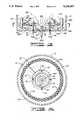
- FIG. 4is a plan view taken at 4--4 in FIG. 3.
- FIG. 5is a plan view of a modified burner tile similar to that shown in FIG. 3 with the exception that the modified burner tile of FIG. 5 has been provided several access openings in which are mounted eductor pumps.
- FIG. 6is a view, somewhat enlarged, taken at 6--6 in FIG. 5.
- furnace assembly 10which is typical of such units found in the prior art; that is, the furnace assembly 10 illustrates the components usually found in such prior art units.
- the furnace assembly 10has a cylindrically shaped body section 12, a converging medial section 14, a stack section 16, and a furnace floor 18. It will be appreciated that FIG. 1 is illustrative only, and that numerous details of the structure, such as valving, piping, controls, insulation etc., have been omitted throughout the drawings in order to present the disclosure more clearly as such details will be known by a person skilled in the combustion art.
- the furnace assembly 10has a convection section 20 in which is disposed a tube arrangement 22.
- a tube arrangement 22Provided within the body section 12, and vertically extending along furnace wall 12A, are a plurality of wall tubes 24 which are interconnected to form, with the tube arrangement 22, a unitary heating structure which contains a flowing material, such as water, which is heated by the furnace assembly 10.
- the furnace assembly 10forms a combustion cavity 26 which is generally within the confine of the body section 12.
- a burner assembly 28is supported on the furnace floor 18, and a flue gas deflection barrier 30 (or sometimes a burner tile or the like) is supported concentrically about the burner assembly 28.
- Fuelis fed via a fuel line 32 to a fuel dispensing nozzle (not shown) centrally disposed to a burner tile 34.
- Combustion air, or some other oxygen bearing fluidsuch as a mixture of air and externally recirculated flue gas, is fed to an inlet port (not shown) in the furnace floor 18.
- a combustion flame 36is created in the combustion cavity 26 which produces combustion products exhausted as a flue gas effluent 38 from the stack section 16.
- a flame ignitornot shown
- a combustion flame 36is created in the combustion cavity 26 which produces combustion products exhausted as a flue gas effluent 38 from the stack section 16.
- temperature gradientsnecessarily occur throughout the tubular furnace assembly 10, causing internal recirculation of a port of the flue gas generated.
- Downdraft of flue gasis especially pronounced between the wall tubes 24 and the furnace wall 12A for the reason that the gases on the flame side of the wall tubes 24, due to direct exposure to the combustion flame 36, have a higher average temperature than do the gases between the back side of the wall tubes 24 and the furnace wall 12A. This results in downdrafted flue gas 38A as denoted by the flow arrows so enumerated in FIG. 1.
- FIG. 2is a more detailed and enlarged view of a prior art burner assembly 28A, and with the exception that the burner assembly 28A is a staged fuel burner, it is identical to the above described burner assembly 28. Accordingly, the numerals used in FIG. 1 will be used in FIG. 2 to designate the same components.
- the burner assembly 28Ahas the fuel line 32 supporting a fuel dispensing nozzle 40, sometimes referred to as the primary fuel nozzle, and it has a plurality of fuel risers or lines 42 peripherally disposed about the burner tile 34. Supported on each of the upper ends of the fuel lines 42 is a secondary fuel dispensing nozzle 44. Combustion air, or a mixture of air and flue gas, is provided to the combustion flame 36 via an inlet port 46 in the furnace floor 18.
- the major portion of fuel to the furnace assembly 10is dispensed through the secondary fuel dispensing nozzles 44, while a minor portion of the fuel is dispensed via the first fuel dispensing nozzle 40.
- the fuel to the first fuel dispensing nozzle 40is reduced and sometimes eliminated during operation, in which case the first fuel dispensing nozzle 40 serves as a flame holder.
- the downdrafted flue gas 38Apasses downwardly between the wall tubes 24 and the furnace wall 12A and turns toward the combustion flame 36 where it is drawn upwardly along the outer edges of the flame envelope.
- the deflection barrier 30serves to turn that portion of the downdrafted flue gas 38A which would flow toward the lower part of the combustion flame 36.
- the deflection barrier 30,also known as a Reed wall, or some other obstruction, such as burner tile or the like is commonly provided with prior art burner assemblies to minimize interaction of the downdrafted flue gas 38A with the combustion flame 36 at the fuel ignition point of the flame (that is, at the base of the flame) as such interaction results in flame instability, often causing flame snuffing or incomplete fuel combustion.
- FIGS. 3 and 4depict a burner assembly 50 which is constructed in accordance with the present invention.
- the burner assembly 5also is a staged fuel burner and is similar to the burner assembly 28A, with the exceptions that will be noted.
- the burner assembly 50comprises the fuel line 32 central to, and extensive through, the combustion air inlet port 46 in the furnace floor 18.
- the burner tile 34is a generally cylindrically shaped member which circumscribes the first fuel dispensing nozzle 40, and a plurality of fuel lines 42, supporting the secondary fuel dispensing nozzles 44, are peripherally disposed about the burner tile 34.
- the burner assembly 50does not have a fluid gas barrier such as the deflection barrier 30 shown with the burner assembly 28A.
- a fluid gas barriersuch as the deflection barrier 30 shown with the burner assembly 28A.
- the burner assembly 50also comprises a flue gas recirculating system 52 which is disposed in the furnace assembly 10 for the purpose of flowing internal recirculating flue gas into combustion reaction with the combustion flame 36, leading to the minimization or elimination of NO x content in the flue gas effluent 38 from the stack 16.
- the flue gas recirculating system 52has a flue gas gathering member 54, sometimes also referred to as a barrier member, which is disposed in close proximity to the furnace floor 18.
- the flue gas gathering member 54has a central opening 56 which is, by positioning of the flue gas gathering member 54, disposed about the burner tile 34, leaving an annular gap 56A in which the secondary fuel dispensing nozzles 44 are disposed.
- the flue gas gathering member 54in cooperation with the furnace floor 18, forms a flue gas tunnel 58, or passageway, which is open near the furnace wall 12A so that some portion of the downdrafted flue gas 38A is collected therein and caused to pass through the annular gap 56A.
- the placement of the secondary fuel dispensing nozzles 44 in the annular gap 56A peripherally about the burner tile 34, and thus about the first fuel dispensing nozzle 40,causes the secondary fuel dispensing nozzles 44 to serve as aspirators and, cooperating with the flue gas gathering member 54, the secondary fuel dispensing nozzles 44 aspirate a quantity of the downdrafted flue gas 38A from the flue gas tunnel 58 through the flue gas discharge gap 56A.
- the downdrafted flue gas 38A in the flue gas tunnel 58is aspirated or driven into the combustion cavity 26 to effect reaction with the combustion flame 36 so that the flue gas effluent 38 from the stack section 16 is caused to have a substantially diminished NO x content.
- the aspirating or driving force of the secondary fuel dispensing nozzles 44is one way in which to pass the collected flue gas 38A from the flue gas tunnel 58 into the combustion zone 26. Another way is depicted in FIGS. 5 and 6.
- a burner tile 34Ais provided which is identical to the burner tile 34 described hereinabove except that the burner tile 34A is provided with several access openings 60 extending through the cylindrical wall at angles ⁇ and/or ⁇ sufficient to provide gas passage at a direction which is off center to the centrally disposed first fuel dispensing nozzle 40.
- the flue gas recirculating forceis provided by several eductor pumps 62, one each of such eductor pumps 62 being disposed to have its outlet end 62A fitted into one of the access openings 60 as shown in FIG. 6.
- the body of each eductor pump 62has a diverging shape as is conventionally known, and is disposed in the tunnel 58 so that its open inlet end 62B is in communication with the collected flue gas 38A in the tunnel 58.
- a steam conduit 64interconnects all of the eductor pumps 62 and provides pressurized steam to each of the eductor pumps 62 through a jet portion 62C at the inlet end 62B of each one.
- Pressurized steamis fed through the eductor pumps 62 where pressure head is converted to velocity head to draw flue gas 38A from the tunnel 58 and to forcefully propel the mixture of steam and flue gas toward the combustion flame 36. While steam is mentioned as the driving fluid since steam is a frequently available pressurized fluid, other pressurized fluids can also be used effectively to power the eductor pumps 62.
- the flue gas recirculating system 52can be provided with either the driving force of the secondary fuel dispensing nozzles 44 or the eductor pumps 62, or the flue gas recirculating system 52 can be provided with both the driving force of the secondary fuel dispensing nozzles 44 in combination with that of the eductor pumps 62.
- the present inventionwas demonstrated by data obtained during an extensive test object.
- the test projectwas carried out using a furnace unit similar to that shown (FIGS. 3 through 6) and described hereinabove to determine the amount of NO x reduction achieved by the present invention.
- the objective of the test projectwas to demonstrate that a burner constructed in accordance with the present invention will produce reduced levels of nitrogen oxides during a combustion process utilizing recirculation of combustion gas products within a fired tubular furnace.
- the prior arthas demonstrated that reduced NO x levels can be achieved by externally recirculating the combustion products from a furnace stack to a burner. That is, a portion of the stack gas effluent is returned to the inlet of the burner.
- this method of recirculationrequires substantial equipment and modification to the furnace.
- the present inventionusing internal recirculation of flue gas, also results in reduced levels of NO x using a less expensive installation of structure as described hereinabove.
- the test unithad a staged fuel burner which split the fuel into two streams to provide a primary and a secondary combustion zone within the combustion flame.
- the test unit using this burnershowed that the present invention provides the ability to utilize internally recirculated combustion products to reduce NO x levels to substantially below that achieved by a conventional staged fuel burner.
- test unitwas operated at a flue gas oxygen content ranging from less than 1% to greater than 6% by volume.
- the major parameter investigated by the test projectwas the rate of internal flue gas recirculation.
- the primary difference between the burner assembly of the present invention and that of a conventional burneris the ability of the present invention to utilize internally recirculated flue gas to further reduce the formation of NO x during a combustion process.
- Several recirculation rates of flue gaswere investigated, with the recirculation flue gas being injected into the primary combustion zone by steam driven eductor pumps. Eductor steam pressure was used as a measure of the recirculation rate.
- test unit on which the test project data was obtainedwas first operated in a configuration generally in conformity with that shown in FIGS. 1 and 2 herein. That is, the test unit was first operated without the installation of the flue gas recirculation system of the present invention for the purpose of establishing baseline NO x emission levels for the furnace before the installation of the present invention.
- This datais presented in Table 1 in which is recorded the results of four separate runs using natural gas as the fuel.
- the staged fuel burnerwas run utilizing 30% of the fuel to the primary (center) fuel nozzle and 70% of the fuel to the secondary fuel nozzles peripherally disposed about the primary fuel nozzle. Air was introduced into the burner in a single stage central opening by natural draft.
- the following parameterswere measured: stack temperature; firebox temperature; and firing rate (reported in million BTUs per hour).
- the stack gas effluentwas monitored using a Teledyne Max 5 flue gas analyzer to determine the excess oxygen (O 2 %) and carbon monoxide (CO ppm).
- NO x emissionwas measured using a Thermo Electron Model 10 chemiluminescent NO x analyzer (NO x ppm). NO x is normally reported at 3 percent excess oxygen; therefore, the measured NO x was corrected to this level and is reported as NO x (corrected ppm).
- Run 4 in Table 1is at a reduced firing rate (1.4 MMBTU/HR) and at a high excess oxygen level (13.81%). This represents the high NO x emission level achieved during a startup or during a hot standby condition.
- Table IIis broken down into 9 tests, and each of these tests has a plurality of runs to demonstrate the effect of the different variables. A description of each such test follows.
- Test 1The test fuel was natural gas. Effluent oxygen concentration was held in the 2.5% range over the 6 runs that made up the test. The furnace temperature was held as near 1300° F. as possible. Firing rate was held at a constant 4.4 MM BTU/hr. Fuel split was 70% secondary fuel nozzles and 30% primary fuel nozzle. Internally recirculated flue products were driven by means of the eductors into the primary combustion zone. As the eductor pressure increased more internally recirculated flue gas was moved from the gathering system area into the primary combustion zone. Runs 1 thru 6 show the downward trend of NO x formation caused by the injection of internally recirculated flue gas into the primary combustion zone.
- Run 1with no recirculation into the primary zone by the eductor pumps, while showing a sizable reduction from the baseline data, did not meet the effluent NO x requirement of approximately 25 ppm for natural gas fuel.
- Run #6shows total NO x emission from the furnace of 13.2 ppm. This represents a reduction of 62% from the baseline data. It also demonstrates a reduction of 48% from the furnace configuration without the primary zone eductors. This results in a substantial reduction from the target (0.03 LBS/MM BTU) NO x emission.
- Test block conditionswere held constant as in Test 1 with the exception that the effluent oxygen concentration was increased to approximately 3%.
- the fuelwas natural gas.
- Runs 8-11show the effect of the educted flue gas when introduced into the primary combustion zone. When data from Run 11 is compared with the baseline data, a reduction of 44% in NOx emission is shown. When Run 11 data is compared with Run 7, a reduction of 47% in NOx reduction is shown. These reductions show the effect of using both the flue gas gathering member and the eductor pumps. The rise in the corrected NO x shows the effect of effluent oxygen concentration on thermal NO x production.
- Test 3The fuel was natural gas, and the firing rate (4.4 MM BTU/HR) was held at the same rate as in Tests 1 and 2. The effluent oxygen concentration was held around 2.5%. The box temperature was raised to around 1375° F. Fuel split was altered to pass 80% through the secondary fuel nozzles and 20% through the primary fuel nozzle. Again, the eductor pressure (STM DRV PR) was varied. Run No. 12 registered a NO x emission level of 25.5 ppm. When this data is compared with the baseline data of Table I, a reduction of 26% was achieved. As the eductor pressure was increased in Runs 13-16, a decrease in NO x emission was experienced. The best result is shown in Run #16 (12.2 ppm). This shows a reduction from the baseline of 65% and a reduction from Run #12 of 52%. The lower NO x emissions were attributed to the change in fuel split.
- Test 4The fuel was 80% hydrogen and 20% natural gas. The firing rate was 4.5 MM BTU/HR. Fuel split was 70% to the secondary fuel nozzles and 30% to the primary fuel nozzle. The oxygen concentration was held in the 2-3% range. The furnace temperature was held around 1300° F. Runs 17-19 show the effect of using the eductor pumps to inject internally recirculated gas into the primary combustion zone of the flame. The NO x emission limit for this fuel at 0.03 LBS/MM BTUs is around 30 ppm. Run 18 achieved the best reduction (32%) compared with the 0.03 LBS/MM BTUs limit. The fuel utilized in this test is known to be a high NO x producer is typical of fuels found in certain petrochemical process plants.
- Test 5The fuel was natural gas. The furnace temperature was held around 1500° F. The eductor pressure was maintained fairly constant. Heat release was held at 4.5 MM BTU/HR for Runs 20-23. Fuel split was 70% to the secondary fuel nozzles and 30% to the primary fuel nozzle. Oxygen concentration was varied from around 2% to 4.8%. Run 21 demonstrated the effect of effluent oxygen concentration on NO x emission when compared with Run 22. As expected, the NO x emission rose with increasing oxygen concentration. Still, a substantial reduction (51%) was achieved when comparing Run 21 to the baseline data of Table I. When compared with the NO x emission limit of 0.03 lbs/MM BTUs (25 ppm) for natural gas as the operating fuel, a reduction of 32% was demonstrated.
- Test 6The fuel was a mixture of 30% hydrogen, 35% natural gas and 35% propane. This represents a typical refinery fuel gas.
- the eductor pressure (STM DRV PR)was varied.
- the furnace temperaturewas varied from 1300° F. to 1575° F.
- the firing ratewas held constant at 4.5 MM BTU/Hr.
- Fuel splitwas 70% to the secondary fuel nozzles and 30% to the primary fuel nozzle.
- the effluent oxygen concentrationwas varied in the 2 to 4 percent range.
- the allowable NO x emission limit of 0.03 lbs/MM BTUs level for this fuelequates to a NOx emission of 25.2 ppm. Runs No. 24-28 show the effect of the increasing the furnace temperature on the NO x emission level.
- Run 34shows a reduction in the NO x emission of 26% in spite of a 100° F. furnace temperature increase.
- Test 36shows that at 1.85% oxygen concentration and at 1500° F. box temperature, a reduction of 38% was achieved relative to Run 27. A difference of 15% was demonstrated between Run 34 and the 0.03 lbs/MM BTU limit.
- Test 7The fuel was a mixture of 50% hydrogen and 50% natural gas. The eductor pressure was varied between runs, and the furnace temperature was varied as well as oxygen content. The firing rate was held constant at 4.5 MM BTU/Hr. Fuel split was 70% to the secondary fuel nozzles and 30% to the primary fuel nozzle. The allowable NO x emission level of 0.03 lbs/MM BTUs equates to a limit of 27.0 ppm for this fuel. Run 37 can be used as a baseline for this fuel. It shows a corrected NO x of 31.3 ppm and a box temperature of approximately 1300° F. Runs 38-42 varied the oxygen concentration and the box temperature while holding the eductor pressure (STM DRV PR) constant at 12.0 psig.
- STM DRV PReductor pressure
- Test 8The fuel was 50% hydrogen, 30% natural gas and 20% propane, again representing a typical refinery fuel gas. The 0.03 lbs/MM BTUs level for this fuel is 26.1 ppm. Runs 46-50 were conducted at a 3.8 MM BTU/HR heat release. Runs 51 and 52 were at 4.75 MM BTU/HR, and Run 53 represents a turn down case at 1.4 MM BTU/HR All runs were at a constant eductor pressure. In Runs 46-49, with the firebox temperature of approximately 1350° F., the O 2 was varied from 2.18% to 6.03%. Runs 51 and 52 were conducted at a constant 1400° F. box temperature, and O 2 concentration was varied from 1.7% to 3.6%.
- Run 53represents the conditions experienced for a furnace during a turn down, a start up condition or a hot standby condition as this run was conducted with a high excess oxygen concentration of 6.3%. All of the reported NO x emission levels were under the 26.1 ppm limit. It should also be noted that the eductor pressure was not decreased during Run 53, indicating the high stability of the flame.
- Test 9The fuel was 30% hydrogen, 35% natural gas and 35% propane. Again, the eductor pressure was held fairly constant at 20.0 and 25.0 psig. The firebox temperature was allowed to increase from a startup condition of 825° F. to a maximum of 1450° F. The oxygen concentration was varied from between 1.95% to 5.85%. The allowable NOx emission limit of 0.03 lbs/MM BTUs for this fuel is 25.2. Run 54 shows a furnace turn down condition with a high excess oxygen concentration of 7.13%, and the NO x emission level of 29.2 ppm exceeds the allowed level of 25.2 ppm. Runs 55-59 were conducted at 3.8 MM BTU/HR heat release and at a fairly constant box temperature of 1375° F.
- Runs 55-59were below the acceptable 25.2 ppm limit.
- Runs 60-62were conducted with an increase in firing rate to 4.75 MM BTU/HR and the oxygen concentration was varied between 1.95% and 4.15%. Again, in Runs 60-62 the NO x was below the 25.2 ppm limit.
Landscapes
- Engineering & Computer Science (AREA)
- Chemical & Material Sciences (AREA)
- Combustion & Propulsion (AREA)
- Mechanical Engineering (AREA)
- General Engineering & Computer Science (AREA)
Abstract
Description
TABLE 1 ______________________________________ BASELINE DATA RUNNUMBER 1 2 3 4 ______________________________________ O.sub.2 (%) 1.87 2.20 2.10 13.81 NO.sub.X (MEASURED PPM) 36.8 40.4 40.6 21.5 NO.sub.X (CORRECTED PPM) 34.6 38.7 38.7 53.8 CO (PPM) 76.0 29.0 24.0 141.0 STACK TEMP (°F.) 1308 1388 1410 901 FIREBOX TEMP (°F.) 1314 1379 1403 1009 HEAT REL (MMBTU/HR) 4.5 4.5 4.5 1.4 ______________________________________
TABLE 2 __________________________________________________________________________TEST DATA __________________________________________________________________________TEST 1 2 RUN NUMBER 1 2 3 4 5 6 7 8 9 10 11 __________________________________________________________________________O.sub.2 (%) 2.58 2.50 2.38 2.48 2.47 2.42 3.11 2.97 2.81 3.16 3.13 NO.sub.X (MEASURED PPM) 27.4 22.1 20.0 18.5 19.0 13.6 28.5 25.2 19.5 17.6 15.1 NO.sub.X (CORRECTED PPM) 26.8 21.5 19.3 18.0 18.4 13.2 28.6 25.2 19.3 17.7 15.2 CO (PPM) 56.0 51.0 46.0 53.0 109.0 214.0 23.0 27.0 40.0 52.0 129.0 STACK TEMP (°F.) 1276 1308 1332 1330 1331 1318 1310 1322 1323 1313 1313 FIREBOX TEMP (°F.) 1321 1333 1338 1329 1361 1297 1323 1326 1323 1304 1299 HEAT REL (MMBTU/HR) 4.4 4.4 4.4 4.4 4.4 4.4 4.4 4.4 4.4 4.4 4.4 STM DRV PR (PSIG) 0 2 4 6 10 12 0 2 6 10 14 __________________________________________________________________________TEST 3 4 RUN NUMBER 12 13 14 15 16 17 18 19 __________________________________________________________________________O.sub.2 (%) 2.61 2.54 2.35 2.51 2.32 2.83 2.02 2.47 NO.sub.X (MEASURED PPM) 26.0 18.7 16.7 15.0 12.7 25.8 21.6 21.4 NO.sub.X (CORRECTED PPM) 25.5 18.3 16.1 14.6 12.2 25.6 20.5 20.8 CO (PPM) 25.0 144.0 212.0 162.0 458.0 46.0 40.0 36.0 STACK TEMP (°F.) 1365 1406 1410 1408 1410 1257 1303 1315 FIREBOX TEMP (°F.) 1365 1385 1385 1378 1377 1335 1349 1335 HEAT REL (MMBTU/HR) 4.4 4.4 4.4 4.4 4.4 4.5 4.5 4.5 STM DRV PR (PSIG) 0 4 8 10 15 15 25 35 __________________________________________________________________________TEST 5 6 RUN NUMBER 20 21 22 23 24 25 26 27 28 29 30 __________________________________________________________________________O.sub.2 (%) 2.38 4.77 2.12 1.86 2.92 2.85 1.84 3.15 3.08 2.93 2.16 NO.sub.X (MEASURED PPM) 13.8 15.3 13.9 13.1 25.0 33.9 23.6 29.2 29.6 24.1 26.1 NO.sub.X (CORRECTED PPM) 13.4 16.9 13.3 12.3 24.9 33.6 22.2 29.4 29.8 24.0 24.9 CO (PPM) 13.0 13.0 12.0 11.0 26.0 79.0 64.0 48.0 38.0 32.0 30.0 STACK TEMP (°F.) 1509 1505 1537 1542 1289 1307 1352 1397 1471 1505 1539 FIREBOX TEMP (°F.) 1519 1486 1538 1543 1290 1341 1364 1397 1476 1524 1570 HEAT REL (MMBTU/HR) 4.5 4.5 4.5 4.5 4.5 4.5 4.5 4.5 4.5 4.5 4.6 STM DRV PR (PSIG) 11.5 10.5 10.5 14.0 2.0 2.5 5.0 4.5 4.5 10.0 12.0 __________________________________________________________________________TEST 6 7 RUN NUMBER 31 32 33 34 35 36 37 38 39 40 41 __________________________________________________________________________O.sub.2 (%) 2.45 2.09 3.45 3.79 2.00 1.85 2.91 2.56 3.18 3.10 3.85 NO.sub.X (MEASURED PPM) 21.5 19.9 20.8 20.8 21.5 19.5 31.4 17.7 18.8 21.2 22.8 NO.sub.X (CORRECTED PPM) 20.9 18.9 21.3 21.7 20.3 18.3 31.3 17.3 18.9 21.4 23.9 CO (PPM) 25.0 24.0 24.0 24.0 22.0 21.0 18.0 31.0 9.0 10.0 11.0 STACK TEMP (°F.) 1530 1521 1511 1505 1513 1495 1303 1298 1381 1453 1457 FIREBOX TEMP (°F.) 1524 1514 1487 1477 1498 1463 1293 1288 1393 1473 1468 HEAT REL (MMBTU/HR) 4.5 4.5 4.5 4.5 4.5 4.5 4.5 4.5 4.5 4.5 4.5 STM DRV PR (PSIG) 15.0 20.0 22.0 20.0 15.0 28.0 2.5 12.0 12.0 12.0 12.0 __________________________________________________________________________TEST 7 8 RUN NUMBER 42 43 44 45 46 47 48 49 50 51 52 53 __________________________________________________________________________O.sub.2 (%) 1.80 2.13 2.06 2.13 2.18 2.98 4.02 4.55 6.03 1.70 3.60 6.30 NO.sub.X (MEASURED PPM) 20.0 19.4 17.4 18.0 20.0 20.0 20.7 20.6 20.6 20.9 23.1 18.6 NO.sub.X (CORRECTED PPM) 18.8 18.5 16.5 17.2 19.1 20.0 21.9 22.5 24.7 19.5 23.9 22.0 CO (PPM) 8.0 8.0 7.0 7.0 57.0 21.0 20.0 18.0 18.0 17.0 18.0 261 STACK TEMP (°F.) 1488 1491 1484 1476 FIREBOX TEMP (°F.) 1511 1509 1591 1478 1388 1353 1345 1340 1292 1416 1399 961 HEAT REL (MMBTU/HR) 4.5 4.5 4.5 4.5 3.8 3.8 3.8 3.8 3.8 4.75 4.75 1.4 STM DRV PR (PSIG) 12.0 15.0 20.0 25.0 25.0 25.0 25.0 25.0 25.0 25.0 25.0 25.0 __________________________________________________________________________TEST 9 RUN NUMBER 54 55 56 57 58 59 60 61 62 __________________________________________________________________________O.sub.2 (%) 7.13 2.27 2.66 4.17 5.85 5.21 2.16 1.95 4.15 NO.sub.X (MEASURED PPM) 22.5 16.9 19.4 18.6 18.2 16.7 16.2 18.0 20.9 NO.sub.X (CORRECTED PPM) 29.2 16.2 19.0 19.9 21.6 19.0 15.5 17.0 22.3 CO (PPM) 106.0 36.0 33.0 29.0 28.0 26.0 20.0 19.0 19.0 STACK TEMP (°F.) FIREBOX TEMP (°F.) 825 1384 1434 1377 1349 1313 1380 1436 1450 HEAT REL (MMBTU/HR) 1.4 3.8 3.8 3.8 3.8 3.8 4.75 4.75 4.75 STM DRV PR (PSIG) 20.0 25.0 25.0 25.0 20.0 20.0 20.0 20.0 20.0 __________________________________________________________________________
Claims (3)
Priority Applications (2)
| Application Number | Priority Date | Filing Date | Title |
|---|---|---|---|
| US07/719,520US5135387A (en) | 1989-10-19 | 1991-06-24 | Nitrogen oxide control using internally recirculated flue gas |
| US08/063,362US5316469A (en) | 1989-10-19 | 1993-05-18 | Nitrogen oxide control using internally recirculated flue gas |
Applications Claiming Priority (2)
| Application Number | Priority Date | Filing Date | Title |
|---|---|---|---|
| US07/423,145US5044932A (en) | 1989-10-19 | 1989-10-19 | Nitrogen oxide control using internally recirculated flue gas |
| US07/719,520US5135387A (en) | 1989-10-19 | 1991-06-24 | Nitrogen oxide control using internally recirculated flue gas |
Related Parent Applications (1)
| Application Number | Title | Priority Date | Filing Date |
|---|---|---|---|
| US07/423,145ContinuationUS5044932A (en) | 1989-10-19 | 1989-10-19 | Nitrogen oxide control using internally recirculated flue gas |
Related Child Applications (1)
| Application Number | Title | Priority Date | Filing Date |
|---|---|---|---|
| US91757692AContinuation | 1989-10-19 | 1992-07-21 |
Publications (1)
| Publication Number | Publication Date |
|---|---|
| US5135387Atrue US5135387A (en) | 1992-08-04 |
Family
ID=27025892
Family Applications (1)
| Application Number | Title | Priority Date | Filing Date |
|---|---|---|---|
| US07/719,520Expired - Fee RelatedUS5135387A (en) | 1989-10-19 | 1991-06-24 | Nitrogen oxide control using internally recirculated flue gas |
Country Status (1)
| Country | Link |
|---|---|
| US (1) | US5135387A (en) |
Cited By (108)
| Publication number | Priority date | Publication date | Assignee | Title |
|---|---|---|---|---|
| US5316469A (en)* | 1989-10-19 | 1994-05-31 | Koch Engineering Company, Inc. | Nitrogen oxide control using internally recirculated flue gas |
| US5338186A (en)* | 1992-12-04 | 1994-08-16 | Nikolai Sulzhik | Radiation burner |
| US5407347A (en)* | 1993-07-16 | 1995-04-18 | Radian Corporation | Apparatus and method for reducing NOx, CO and hydrocarbon emissions when burning gaseous fuels |
| US5407345A (en)* | 1993-04-12 | 1995-04-18 | North American Manufacturing Co. | Ultra low NOX burner |
| US5441404A (en)* | 1993-01-29 | 1995-08-15 | Gordan-Piatt Energy Group, Inc. | Burner assembly for reducing nitrogen oxides during combustion of gaseous fuels |
| US5470224A (en)* | 1993-07-16 | 1995-11-28 | Radian Corporation | Apparatus and method for reducing NOx , CO and hydrocarbon emissions when burning gaseous fuels |
| WO1996001968A1 (en)* | 1994-07-11 | 1996-01-25 | Nikolai Sulzhik | Radiation burner |
| US5545031A (en)* | 1994-12-30 | 1996-08-13 | Combustion Tec, Inc. | Method and apparatus for injecting fuel and oxidant into a combustion burner |
| US5567141A (en)* | 1994-12-30 | 1996-10-22 | Combustion Tec, Inc. | Oxy-liquid fuel combustion process and apparatus |
| US5584182A (en)* | 1994-04-02 | 1996-12-17 | Abb Management Ag | Combustion chamber with premixing burner and jet propellent exhaust gas recirculation |
| US5634785A (en)* | 1994-03-29 | 1997-06-03 | Entreprise Generale De Chauffage Industriel Pillard | Gas burner with very small nitrogen oxide emission |
| US5667376A (en)* | 1993-04-12 | 1997-09-16 | North American Manufacturing Company | Ultra low NOX burner |
| US5725367A (en)* | 1994-12-30 | 1998-03-10 | Combustion Tec, Inc. | Method and apparatus for dispersing fuel and oxidant from a burner |
| US5795146A (en)* | 1996-05-23 | 1998-08-18 | Btu International, Inc. | Furnace chamber having eductor to enhance thermal processing |
| US6010329A (en)* | 1996-11-08 | 2000-01-04 | Shrinkfast Corporation | Heat gun with high performance jet pump and quick change attachments |
| US6227846B1 (en) | 1996-11-08 | 2001-05-08 | Shrinkfast Corporation | Heat gun with high performance jet pump and quick change attachments |
| EP1335163A1 (en)* | 2002-01-31 | 2003-08-13 | Air Products And Chemicals, Inc. | Ultra low NOx burner for process heating |
| US20030175634A1 (en)* | 2002-03-16 | 2003-09-18 | George Stephens | Burner with high flow area tip |
| US20030175632A1 (en)* | 2002-03-16 | 2003-09-18 | George Stephens | Removable light-off port plug for use in burners |
| US20030175639A1 (en)* | 2002-03-16 | 2003-09-18 | Spicer David B. | Burner employing flue-gas recirculation system |
| US20030175646A1 (en)* | 2002-03-16 | 2003-09-18 | George Stephens | Method for adjusting pre-mix burners to reduce NOx emissions |
| US20030175635A1 (en)* | 2002-03-16 | 2003-09-18 | George Stephens | Burner employing flue-gas recirculation system with enlarged circulation duct |
| US20030175637A1 (en)* | 2002-03-16 | 2003-09-18 | George Stephens | Burner employing cooled flue gas recirculation |
| US6638061B1 (en) | 2002-08-13 | 2003-10-28 | North American Manufacturing Company | Low NOx combustion method and apparatus |
| US20040018461A1 (en)* | 2002-03-16 | 2004-01-29 | George Stephens | Burner with low NOx emissions |
| US20040241601A1 (en)* | 2002-03-16 | 2004-12-02 | Spicer David B. | Burner tip for pre-mix burners |
| US6866502B2 (en) | 2002-03-16 | 2005-03-15 | Exxonmobil Chemical Patents Inc. | Burner system employing flue gas recirculation |
| US6881053B2 (en) | 2002-03-16 | 2005-04-19 | Exxonmobil Chemical Patents Inc. | Burner with high capacity venturi |
| US6884062B2 (en) | 2002-03-16 | 2005-04-26 | Exxonmobil Chemical Patents Inc. | Burner design for achieving higher rates of flue gas recirculation |
| US6887068B2 (en) | 2002-03-16 | 2005-05-03 | Exxonmobil Chemical Patents Inc. | Centering plate for burner |
| US6890172B2 (en) | 2002-03-16 | 2005-05-10 | Exxonmobil Chemical Patents Inc. | Burner with flue gas recirculation |
| US6893252B2 (en) | 2002-03-16 | 2005-05-17 | Exxonmobil Chemical Patents Inc. | Fuel spud for high temperature burners |
| US6893251B2 (en) | 2002-03-16 | 2005-05-17 | Exxon Mobil Chemical Patents Inc. | Burner design for reduced NOx emissions |
| US20050194333A1 (en)* | 2004-03-05 | 2005-09-08 | Beckman Coulter, Inc. | Specimen-container rack for automated clinical instrument |
| US6986658B2 (en) | 2002-03-16 | 2006-01-17 | Exxonmobil Chemical Patents, Inc. | Burner employing steam injection |
| US20070154855A1 (en)* | 2006-01-05 | 2007-07-05 | Great Southern Flameless, Llc | System, apparatus and method for flameless combustion absent catalyst or high temperature oxidants |
| KR100837713B1 (en) | 2006-04-26 | 2008-06-13 | 에어 프로덕츠 앤드 케미칼스, 인코오포레이티드 | ULTRA-LOW NOx BURNER ASSEMBLY |
| US20080206693A1 (en)* | 2004-02-25 | 2008-08-28 | John Zink Company, Inc. | Low NOx burner |
| CN100431670C (en)* | 2006-04-07 | 2008-11-12 | 北京布鲁斯盖环保科技发展有限公司 | Energy-saving method for denitrogenation of horizontal chained coal fired boiler |
| US7815254B2 (en) | 2005-07-22 | 2010-10-19 | Swimways Corporation | Canopy chair |
| US20130269576A1 (en)* | 2010-11-18 | 2013-10-17 | Linde Aktiengesellschaft | Burner with adjustable flue gas recirculation |
| US8734545B2 (en) | 2008-03-28 | 2014-05-27 | Exxonmobil Upstream Research Company | Low emission power generation and hydrocarbon recovery systems and methods |
| US8984857B2 (en) | 2008-03-28 | 2015-03-24 | Exxonmobil Upstream Research Company | Low emission power generation and hydrocarbon recovery systems and methods |
| US9027321B2 (en) | 2008-03-28 | 2015-05-12 | Exxonmobil Upstream Research Company | Low emission power generation and hydrocarbon recovery systems and methods |
| US20150369126A1 (en)* | 2014-06-18 | 2015-12-24 | Alstom Technology Ltd | Method for recirculation of exhaust gas from a combustion chamber of a combustor of a gas turbine and gas turbine for doncuting said method |
| US9222671B2 (en) | 2008-10-14 | 2015-12-29 | Exxonmobil Upstream Research Company | Methods and systems for controlling the products of combustion |
| US9353682B2 (en) | 2012-04-12 | 2016-05-31 | General Electric Company | Methods, systems and apparatus relating to combustion turbine power plants with exhaust gas recirculation |
| US9463417B2 (en) | 2011-03-22 | 2016-10-11 | Exxonmobil Upstream Research Company | Low emission power generation systems and methods incorporating carbon dioxide separation |
| US9512759B2 (en) | 2013-02-06 | 2016-12-06 | General Electric Company | System and method for catalyst heat utilization for gas turbine with exhaust gas recirculation |
| US9574496B2 (en) | 2012-12-28 | 2017-02-21 | General Electric Company | System and method for a turbine combustor |
| US9581081B2 (en) | 2013-01-13 | 2017-02-28 | General Electric Company | System and method for protecting components in a gas turbine engine with exhaust gas recirculation |
| US9587510B2 (en) | 2013-07-30 | 2017-03-07 | General Electric Company | System and method for a gas turbine engine sensor |
| US9599070B2 (en) | 2012-11-02 | 2017-03-21 | General Electric Company | System and method for oxidant compression in a stoichiometric exhaust gas recirculation gas turbine system |
| US9599021B2 (en) | 2011-03-22 | 2017-03-21 | Exxonmobil Upstream Research Company | Systems and methods for controlling stoichiometric combustion in low emission turbine systems |
| JP2017062105A (en)* | 2016-11-29 | 2017-03-30 | ボルカノ株式会社 | Combustor |
| US9611756B2 (en) | 2012-11-02 | 2017-04-04 | General Electric Company | System and method for protecting components in a gas turbine engine with exhaust gas recirculation |
| US9618261B2 (en) | 2013-03-08 | 2017-04-11 | Exxonmobil Upstream Research Company | Power generation and LNG production |
| US9617914B2 (en) | 2013-06-28 | 2017-04-11 | General Electric Company | Systems and methods for monitoring gas turbine systems having exhaust gas recirculation |
| US9631542B2 (en) | 2013-06-28 | 2017-04-25 | General Electric Company | System and method for exhausting combustion gases from gas turbine engines |
| US9631815B2 (en) | 2012-12-28 | 2017-04-25 | General Electric Company | System and method for a turbine combustor |
| US9670841B2 (en) | 2011-03-22 | 2017-06-06 | Exxonmobil Upstream Research Company | Methods of varying low emission turbine gas recycle circuits and systems and apparatus related thereto |
| US9689309B2 (en) | 2011-03-22 | 2017-06-27 | Exxonmobil Upstream Research Company | Systems and methods for carbon dioxide capture in low emission combined turbine systems |
| US9708977B2 (en) | 2012-12-28 | 2017-07-18 | General Electric Company | System and method for reheat in gas turbine with exhaust gas recirculation |
| US9732673B2 (en) | 2010-07-02 | 2017-08-15 | Exxonmobil Upstream Research Company | Stoichiometric combustion with exhaust gas recirculation and direct contact cooler |
| US9732675B2 (en) | 2010-07-02 | 2017-08-15 | Exxonmobil Upstream Research Company | Low emission power generation systems and methods |
| US9752458B2 (en) | 2013-12-04 | 2017-09-05 | General Electric Company | System and method for a gas turbine engine |
| US9784140B2 (en) | 2013-03-08 | 2017-10-10 | Exxonmobil Upstream Research Company | Processing exhaust for use in enhanced oil recovery |
| US9784185B2 (en) | 2012-04-26 | 2017-10-10 | General Electric Company | System and method for cooling a gas turbine with an exhaust gas provided by the gas turbine |
| US9784182B2 (en) | 2013-03-08 | 2017-10-10 | Exxonmobil Upstream Research Company | Power generation and methane recovery from methane hydrates |
| US9803865B2 (en) | 2012-12-28 | 2017-10-31 | General Electric Company | System and method for a turbine combustor |
| US9810050B2 (en) | 2011-12-20 | 2017-11-07 | Exxonmobil Upstream Research Company | Enhanced coal-bed methane production |
| US9819292B2 (en) | 2014-12-31 | 2017-11-14 | General Electric Company | Systems and methods to respond to grid overfrequency events for a stoichiometric exhaust recirculation gas turbine |
| US9835089B2 (en) | 2013-06-28 | 2017-12-05 | General Electric Company | System and method for a fuel nozzle |
| US9863267B2 (en) | 2014-01-21 | 2018-01-09 | General Electric Company | System and method of control for a gas turbine engine |
| US9869247B2 (en) | 2014-12-31 | 2018-01-16 | General Electric Company | Systems and methods of estimating a combustion equivalence ratio in a gas turbine with exhaust gas recirculation |
| US9869279B2 (en) | 2012-11-02 | 2018-01-16 | General Electric Company | System and method for a multi-wall turbine combustor |
| US9885290B2 (en) | 2014-06-30 | 2018-02-06 | General Electric Company | Erosion suppression system and method in an exhaust gas recirculation gas turbine system |
| US9903588B2 (en) | 2013-07-30 | 2018-02-27 | General Electric Company | System and method for barrier in passage of combustor of gas turbine engine with exhaust gas recirculation |
| US9903316B2 (en) | 2010-07-02 | 2018-02-27 | Exxonmobil Upstream Research Company | Stoichiometric combustion of enriched air with exhaust gas recirculation |
| US9903271B2 (en) | 2010-07-02 | 2018-02-27 | Exxonmobil Upstream Research Company | Low emission triple-cycle power generation and CO2 separation systems and methods |
| US9915200B2 (en) | 2014-01-21 | 2018-03-13 | General Electric Company | System and method for controlling the combustion process in a gas turbine operating with exhaust gas recirculation |
| US9932874B2 (en) | 2013-02-21 | 2018-04-03 | Exxonmobil Upstream Research Company | Reducing oxygen in a gas turbine exhaust |
| US9938861B2 (en) | 2013-02-21 | 2018-04-10 | Exxonmobil Upstream Research Company | Fuel combusting method |
| US9951658B2 (en) | 2013-07-31 | 2018-04-24 | General Electric Company | System and method for an oxidant heating system |
| US10012151B2 (en) | 2013-06-28 | 2018-07-03 | General Electric Company | Systems and methods for controlling exhaust gas flow in exhaust gas recirculation gas turbine systems |
| US10030588B2 (en) | 2013-12-04 | 2018-07-24 | General Electric Company | Gas turbine combustor diagnostic system and method |
| US10047633B2 (en) | 2014-05-16 | 2018-08-14 | General Electric Company | Bearing housing |
| US10060359B2 (en) | 2014-06-30 | 2018-08-28 | General Electric Company | Method and system for combustion control for gas turbine system with exhaust gas recirculation |
| US10079564B2 (en) | 2014-01-27 | 2018-09-18 | General Electric Company | System and method for a stoichiometric exhaust gas recirculation gas turbine system |
| US10094566B2 (en) | 2015-02-04 | 2018-10-09 | General Electric Company | Systems and methods for high volumetric oxidant flow in gas turbine engine with exhaust gas recirculation |
| US10100741B2 (en) | 2012-11-02 | 2018-10-16 | General Electric Company | System and method for diffusion combustion with oxidant-diluent mixing in a stoichiometric exhaust gas recirculation gas turbine system |
| US10107495B2 (en) | 2012-11-02 | 2018-10-23 | General Electric Company | Gas turbine combustor control system for stoichiometric combustion in the presence of a diluent |
| US10145269B2 (en) | 2015-03-04 | 2018-12-04 | General Electric Company | System and method for cooling discharge flow |
| CN109099417A (en)* | 2018-09-18 | 2018-12-28 | 浙江三杰能源科技有限公司 | A kind of flue gas forces the low NOx combustion method and device of interior circulation |
| CN109297018A (en)* | 2017-07-24 | 2019-02-01 | 福州华夏蓝天信息科技有限公司 | A kind of low nitrogen burner |
| US10208677B2 (en) | 2012-12-31 | 2019-02-19 | General Electric Company | Gas turbine load control system |
| US10215412B2 (en) | 2012-11-02 | 2019-02-26 | General Electric Company | System and method for load control with diffusion combustion in a stoichiometric exhaust gas recirculation gas turbine system |
| US10221762B2 (en) | 2013-02-28 | 2019-03-05 | General Electric Company | System and method for a turbine combustor |
| US10227920B2 (en) | 2014-01-15 | 2019-03-12 | General Electric Company | Gas turbine oxidant separation system |
| US10253690B2 (en) | 2015-02-04 | 2019-04-09 | General Electric Company | Turbine system with exhaust gas recirculation, separation and extraction |
| US10267270B2 (en) | 2015-02-06 | 2019-04-23 | General Electric Company | Systems and methods for carbon black production with a gas turbine engine having exhaust gas recirculation |
| US10273880B2 (en) | 2012-04-26 | 2019-04-30 | General Electric Company | System and method of recirculating exhaust gas for use in a plurality of flow paths in a gas turbine engine |
| US10316746B2 (en) | 2015-02-04 | 2019-06-11 | General Electric Company | Turbine system with exhaust gas recirculation, separation and extraction |
| US10315150B2 (en) | 2013-03-08 | 2019-06-11 | Exxonmobil Upstream Research Company | Carbon dioxide recovery |
| US10480792B2 (en) | 2015-03-06 | 2019-11-19 | General Electric Company | Fuel staging in a gas turbine engine |
| US10655542B2 (en) | 2014-06-30 | 2020-05-19 | General Electric Company | Method and system for startup of gas turbine system drive trains with exhaust gas recirculation |
| US10788212B2 (en) | 2015-01-12 | 2020-09-29 | General Electric Company | System and method for an oxidant passageway in a gas turbine system with exhaust gas recirculation |
| US11927345B1 (en) | 2019-03-01 | 2024-03-12 | XRG Technologies, LLC | Method and device to reduce emissions of nitrogen oxides and increase heat transfer in fired process heaters |
Citations (6)
| Publication number | Priority date | Publication date | Assignee | Title |
|---|---|---|---|---|
| SU779381A1 (en)* | 1977-11-22 | 1980-11-15 | За витель | Tubular furnace |
| US4257763A (en)* | 1978-06-19 | 1981-03-24 | John Zink Company | Low NOx burner |
| US4277942A (en)* | 1979-02-28 | 1981-07-14 | Kommanditbolaget United Stirling | Exhaust gas recirculation apparatus |
| US4575332A (en)* | 1983-07-30 | 1986-03-11 | Deutsche Babcock Werke Aktiengesellschaft | Method of and burner for burning liquid or gaseous fuels with decreased NOx formation |
| US4613299A (en)* | 1984-06-05 | 1986-09-23 | Tommy Backheim | Device for combustion of a fuel and oxygen mixed with a part of the combustion gases formed during the combustion |
| US4708638A (en)* | 1985-02-21 | 1987-11-24 | Tauranca Limited | Fluid fuel fired burner |
- 1991
- 1991-06-24USUS07/719,520patent/US5135387A/ennot_activeExpired - Fee Related
Patent Citations (6)
| Publication number | Priority date | Publication date | Assignee | Title |
|---|---|---|---|---|
| SU779381A1 (en)* | 1977-11-22 | 1980-11-15 | За витель | Tubular furnace |
| US4257763A (en)* | 1978-06-19 | 1981-03-24 | John Zink Company | Low NOx burner |
| US4277942A (en)* | 1979-02-28 | 1981-07-14 | Kommanditbolaget United Stirling | Exhaust gas recirculation apparatus |
| US4575332A (en)* | 1983-07-30 | 1986-03-11 | Deutsche Babcock Werke Aktiengesellschaft | Method of and burner for burning liquid or gaseous fuels with decreased NOx formation |
| US4613299A (en)* | 1984-06-05 | 1986-09-23 | Tommy Backheim | Device for combustion of a fuel and oxygen mixed with a part of the combustion gases formed during the combustion |
| US4708638A (en)* | 1985-02-21 | 1987-11-24 | Tauranca Limited | Fluid fuel fired burner |
Cited By (142)
| Publication number | Priority date | Publication date | Assignee | Title |
|---|---|---|---|---|
| US5316469A (en)* | 1989-10-19 | 1994-05-31 | Koch Engineering Company, Inc. | Nitrogen oxide control using internally recirculated flue gas |
| US5338186A (en)* | 1992-12-04 | 1994-08-16 | Nikolai Sulzhik | Radiation burner |
| US5441404A (en)* | 1993-01-29 | 1995-08-15 | Gordan-Piatt Energy Group, Inc. | Burner assembly for reducing nitrogen oxides during combustion of gaseous fuels |
| US5722821A (en)* | 1993-01-29 | 1998-03-03 | Gordon-Piatt Energy Group, Inc. | Burner assembly for reducing nitrogen oxides during combustion of gaseous fuels |
| US5407345A (en)* | 1993-04-12 | 1995-04-18 | North American Manufacturing Co. | Ultra low NOX burner |
| US5667376A (en)* | 1993-04-12 | 1997-09-16 | North American Manufacturing Company | Ultra low NOX burner |
| US5554021A (en)* | 1993-04-12 | 1996-09-10 | North American Manufacturing Co. | Ultra low nox burner |
| US5407347A (en)* | 1993-07-16 | 1995-04-18 | Radian Corporation | Apparatus and method for reducing NOx, CO and hydrocarbon emissions when burning gaseous fuels |
| US5470224A (en)* | 1993-07-16 | 1995-11-28 | Radian Corporation | Apparatus and method for reducing NOx , CO and hydrocarbon emissions when burning gaseous fuels |
| US5634785A (en)* | 1994-03-29 | 1997-06-03 | Entreprise Generale De Chauffage Industriel Pillard | Gas burner with very small nitrogen oxide emission |
| US5584182A (en)* | 1994-04-02 | 1996-12-17 | Abb Management Ag | Combustion chamber with premixing burner and jet propellent exhaust gas recirculation |
| US5624253A (en)* | 1994-07-11 | 1997-04-29 | Ilya Zborovsky | Radiation burner |
| WO1996001968A1 (en)* | 1994-07-11 | 1996-01-25 | Nikolai Sulzhik | Radiation burner |
| US5567141A (en)* | 1994-12-30 | 1996-10-22 | Combustion Tec, Inc. | Oxy-liquid fuel combustion process and apparatus |
| US5545031A (en)* | 1994-12-30 | 1996-08-13 | Combustion Tec, Inc. | Method and apparatus for injecting fuel and oxidant into a combustion burner |
| US5725367A (en)* | 1994-12-30 | 1998-03-10 | Combustion Tec, Inc. | Method and apparatus for dispersing fuel and oxidant from a burner |
| US5795146A (en)* | 1996-05-23 | 1998-08-18 | Btu International, Inc. | Furnace chamber having eductor to enhance thermal processing |
| US6010329A (en)* | 1996-11-08 | 2000-01-04 | Shrinkfast Corporation | Heat gun with high performance jet pump and quick change attachments |
| US6227846B1 (en) | 1996-11-08 | 2001-05-08 | Shrinkfast Corporation | Heat gun with high performance jet pump and quick change attachments |
| EP1335163A1 (en)* | 2002-01-31 | 2003-08-13 | Air Products And Chemicals, Inc. | Ultra low NOx burner for process heating |
| EP1335163B2 (en)† | 2002-01-31 | 2012-05-09 | Air Products And Chemicals, Inc. | Ultra low NOx burner for process heating |
| US20040241601A1 (en)* | 2002-03-16 | 2004-12-02 | Spicer David B. | Burner tip for pre-mix burners |
| US6893252B2 (en) | 2002-03-16 | 2005-05-17 | Exxonmobil Chemical Patents Inc. | Fuel spud for high temperature burners |
| US20030175646A1 (en)* | 2002-03-16 | 2003-09-18 | George Stephens | Method for adjusting pre-mix burners to reduce NOx emissions |
| US20030175635A1 (en)* | 2002-03-16 | 2003-09-18 | George Stephens | Burner employing flue-gas recirculation system with enlarged circulation duct |
| US20030175637A1 (en)* | 2002-03-16 | 2003-09-18 | George Stephens | Burner employing cooled flue gas recirculation |
| US20030175634A1 (en)* | 2002-03-16 | 2003-09-18 | George Stephens | Burner with high flow area tip |
| US20040018461A1 (en)* | 2002-03-16 | 2004-01-29 | George Stephens | Burner with low NOx emissions |
| US7476099B2 (en) | 2002-03-16 | 2009-01-13 | Exxonmobil Chemicals Patents Inc. | Removable light-off port plug for use in burners |
| US6846175B2 (en) | 2002-03-16 | 2005-01-25 | Exxonmobil Chemical Patents Inc. | Burner employing flue-gas recirculation system |
| US6866502B2 (en) | 2002-03-16 | 2005-03-15 | Exxonmobil Chemical Patents Inc. | Burner system employing flue gas recirculation |
| US6869277B2 (en) | 2002-03-16 | 2005-03-22 | Exxonmobil Chemical Patents Inc. | Burner employing cooled flue gas recirculation |
| US6877980B2 (en) | 2002-03-16 | 2005-04-12 | Exxonmobil Chemical Patents Inc. | Burner with low NOx emissions |
| US6881053B2 (en) | 2002-03-16 | 2005-04-19 | Exxonmobil Chemical Patents Inc. | Burner with high capacity venturi |
| US6884062B2 (en) | 2002-03-16 | 2005-04-26 | Exxonmobil Chemical Patents Inc. | Burner design for achieving higher rates of flue gas recirculation |
| US6887068B2 (en) | 2002-03-16 | 2005-05-03 | Exxonmobil Chemical Patents Inc. | Centering plate for burner |
| US6890171B2 (en) | 2002-03-16 | 2005-05-10 | Exxonmobil Chemical Patents, Inc. | Apparatus for optimizing burner performance |
| US6890172B2 (en) | 2002-03-16 | 2005-05-10 | Exxonmobil Chemical Patents Inc. | Burner with flue gas recirculation |
| US20030175639A1 (en)* | 2002-03-16 | 2003-09-18 | Spicer David B. | Burner employing flue-gas recirculation system |
| US6893251B2 (en) | 2002-03-16 | 2005-05-17 | Exxon Mobil Chemical Patents Inc. | Burner design for reduced NOx emissions |
| US6902390B2 (en) | 2002-03-16 | 2005-06-07 | Exxonmobil Chemical Patents, Inc. | Burner tip for pre-mix burners |
| US20050147934A1 (en)* | 2002-03-16 | 2005-07-07 | George Stephens | Burner with high capacity venturi |
| US7322818B2 (en) | 2002-03-16 | 2008-01-29 | Exxonmobil Chemical Patents Inc. | Method for adjusting pre-mix burners to reduce NOx emissions |
| US6986658B2 (en) | 2002-03-16 | 2006-01-17 | Exxonmobil Chemical Patents, Inc. | Burner employing steam injection |
| US7025587B2 (en) | 2002-03-16 | 2006-04-11 | Exxonmobil Chemical Patents Inc. | Burner with high capacity venturi |
| US20030175632A1 (en)* | 2002-03-16 | 2003-09-18 | George Stephens | Removable light-off port plug for use in burners |
| US6638061B1 (en) | 2002-08-13 | 2003-10-28 | North American Manufacturing Company | Low NOx combustion method and apparatus |
| US8794960B2 (en)* | 2004-02-25 | 2014-08-05 | John Zink Company, Llc | Low NOx burner |
| US20080206693A1 (en)* | 2004-02-25 | 2008-08-28 | John Zink Company, Inc. | Low NOx burner |
| US20050194333A1 (en)* | 2004-03-05 | 2005-09-08 | Beckman Coulter, Inc. | Specimen-container rack for automated clinical instrument |
| US7331474B2 (en)* | 2004-03-05 | 2008-02-19 | Beckman Coulter, Inc. | Specimen-container rack for automated clinical instrument |
| US9049938B2 (en) | 2005-07-22 | 2015-06-09 | Swimways Corporation | Canopy chair |
| US8517465B2 (en) | 2005-07-22 | 2013-08-27 | Swimways Corporation | Canopy chair |
| US8292362B2 (en) | 2005-07-22 | 2012-10-23 | Swimways Corporation | Canopy chair |
| US7815254B2 (en) | 2005-07-22 | 2010-10-19 | Swimways Corporation | Canopy chair |
| US7909395B2 (en) | 2005-07-22 | 2011-03-22 | Swimways Corporation | Canopy chair |
| US8070220B2 (en) | 2005-07-22 | 2011-12-06 | Swimways Corporation | Canopy chair |
| US20070154855A1 (en)* | 2006-01-05 | 2007-07-05 | Great Southern Flameless, Llc | System, apparatus and method for flameless combustion absent catalyst or high temperature oxidants |
| US20070269755A2 (en)* | 2006-01-05 | 2007-11-22 | Petro-Chem Development Co., Inc. | Systems, apparatus and method for flameless combustion absent catalyst or high temperature oxidants |
| CN100431670C (en)* | 2006-04-07 | 2008-11-12 | 北京布鲁斯盖环保科技发展有限公司 | Energy-saving method for denitrogenation of horizontal chained coal fired boiler |
| KR100837713B1 (en) | 2006-04-26 | 2008-06-13 | 에어 프로덕츠 앤드 케미칼스, 인코오포레이티드 | ULTRA-LOW NOx BURNER ASSEMBLY |
| US8734545B2 (en) | 2008-03-28 | 2014-05-27 | Exxonmobil Upstream Research Company | Low emission power generation and hydrocarbon recovery systems and methods |
| US8984857B2 (en) | 2008-03-28 | 2015-03-24 | Exxonmobil Upstream Research Company | Low emission power generation and hydrocarbon recovery systems and methods |
| US9027321B2 (en) | 2008-03-28 | 2015-05-12 | Exxonmobil Upstream Research Company | Low emission power generation and hydrocarbon recovery systems and methods |
| US9222671B2 (en) | 2008-10-14 | 2015-12-29 | Exxonmobil Upstream Research Company | Methods and systems for controlling the products of combustion |
| US10495306B2 (en) | 2008-10-14 | 2019-12-03 | Exxonmobil Upstream Research Company | Methods and systems for controlling the products of combustion |
| US9719682B2 (en) | 2008-10-14 | 2017-08-01 | Exxonmobil Upstream Research Company | Methods and systems for controlling the products of combustion |
| US9903316B2 (en) | 2010-07-02 | 2018-02-27 | Exxonmobil Upstream Research Company | Stoichiometric combustion of enriched air with exhaust gas recirculation |
| US9903271B2 (en) | 2010-07-02 | 2018-02-27 | Exxonmobil Upstream Research Company | Low emission triple-cycle power generation and CO2 separation systems and methods |
| US9732675B2 (en) | 2010-07-02 | 2017-08-15 | Exxonmobil Upstream Research Company | Low emission power generation systems and methods |
| US9732673B2 (en) | 2010-07-02 | 2017-08-15 | Exxonmobil Upstream Research Company | Stoichiometric combustion with exhaust gas recirculation and direct contact cooler |
| US20130269576A1 (en)* | 2010-11-18 | 2013-10-17 | Linde Aktiengesellschaft | Burner with adjustable flue gas recirculation |
| US9670841B2 (en) | 2011-03-22 | 2017-06-06 | Exxonmobil Upstream Research Company | Methods of varying low emission turbine gas recycle circuits and systems and apparatus related thereto |
| US9463417B2 (en) | 2011-03-22 | 2016-10-11 | Exxonmobil Upstream Research Company | Low emission power generation systems and methods incorporating carbon dioxide separation |
| US9599021B2 (en) | 2011-03-22 | 2017-03-21 | Exxonmobil Upstream Research Company | Systems and methods for controlling stoichiometric combustion in low emission turbine systems |
| US9689309B2 (en) | 2011-03-22 | 2017-06-27 | Exxonmobil Upstream Research Company | Systems and methods for carbon dioxide capture in low emission combined turbine systems |
| US9810050B2 (en) | 2011-12-20 | 2017-11-07 | Exxonmobil Upstream Research Company | Enhanced coal-bed methane production |
| US9353682B2 (en) | 2012-04-12 | 2016-05-31 | General Electric Company | Methods, systems and apparatus relating to combustion turbine power plants with exhaust gas recirculation |
| US10273880B2 (en) | 2012-04-26 | 2019-04-30 | General Electric Company | System and method of recirculating exhaust gas for use in a plurality of flow paths in a gas turbine engine |
| US9784185B2 (en) | 2012-04-26 | 2017-10-10 | General Electric Company | System and method for cooling a gas turbine with an exhaust gas provided by the gas turbine |
| US9611756B2 (en) | 2012-11-02 | 2017-04-04 | General Electric Company | System and method for protecting components in a gas turbine engine with exhaust gas recirculation |
| US10107495B2 (en) | 2012-11-02 | 2018-10-23 | General Electric Company | Gas turbine combustor control system for stoichiometric combustion in the presence of a diluent |
| US10161312B2 (en) | 2012-11-02 | 2018-12-25 | General Electric Company | System and method for diffusion combustion with fuel-diluent mixing in a stoichiometric exhaust gas recirculation gas turbine system |
| US10683801B2 (en) | 2012-11-02 | 2020-06-16 | General Electric Company | System and method for oxidant compression in a stoichiometric exhaust gas recirculation gas turbine system |
| US10215412B2 (en) | 2012-11-02 | 2019-02-26 | General Electric Company | System and method for load control with diffusion combustion in a stoichiometric exhaust gas recirculation gas turbine system |
| US9599070B2 (en) | 2012-11-02 | 2017-03-21 | General Electric Company | System and method for oxidant compression in a stoichiometric exhaust gas recirculation gas turbine system |
| US9869279B2 (en) | 2012-11-02 | 2018-01-16 | General Electric Company | System and method for a multi-wall turbine combustor |
| US10138815B2 (en) | 2012-11-02 | 2018-11-27 | General Electric Company | System and method for diffusion combustion in a stoichiometric exhaust gas recirculation gas turbine system |
| US10100741B2 (en) | 2012-11-02 | 2018-10-16 | General Electric Company | System and method for diffusion combustion with oxidant-diluent mixing in a stoichiometric exhaust gas recirculation gas turbine system |
| US9631815B2 (en) | 2012-12-28 | 2017-04-25 | General Electric Company | System and method for a turbine combustor |
| US9803865B2 (en) | 2012-12-28 | 2017-10-31 | General Electric Company | System and method for a turbine combustor |
| US9574496B2 (en) | 2012-12-28 | 2017-02-21 | General Electric Company | System and method for a turbine combustor |
| US9708977B2 (en) | 2012-12-28 | 2017-07-18 | General Electric Company | System and method for reheat in gas turbine with exhaust gas recirculation |
| US10208677B2 (en) | 2012-12-31 | 2019-02-19 | General Electric Company | Gas turbine load control system |
| US9581081B2 (en) | 2013-01-13 | 2017-02-28 | General Electric Company | System and method for protecting components in a gas turbine engine with exhaust gas recirculation |
| US9512759B2 (en) | 2013-02-06 | 2016-12-06 | General Electric Company | System and method for catalyst heat utilization for gas turbine with exhaust gas recirculation |
| US9938861B2 (en) | 2013-02-21 | 2018-04-10 | Exxonmobil Upstream Research Company | Fuel combusting method |
| US10082063B2 (en) | 2013-02-21 | 2018-09-25 | Exxonmobil Upstream Research Company | Reducing oxygen in a gas turbine exhaust |
| US9932874B2 (en) | 2013-02-21 | 2018-04-03 | Exxonmobil Upstream Research Company | Reducing oxygen in a gas turbine exhaust |
| US10221762B2 (en) | 2013-02-28 | 2019-03-05 | General Electric Company | System and method for a turbine combustor |
| US10315150B2 (en) | 2013-03-08 | 2019-06-11 | Exxonmobil Upstream Research Company | Carbon dioxide recovery |
| US9618261B2 (en) | 2013-03-08 | 2017-04-11 | Exxonmobil Upstream Research Company | Power generation and LNG production |
| US9784140B2 (en) | 2013-03-08 | 2017-10-10 | Exxonmobil Upstream Research Company | Processing exhaust for use in enhanced oil recovery |
| US9784182B2 (en) | 2013-03-08 | 2017-10-10 | Exxonmobil Upstream Research Company | Power generation and methane recovery from methane hydrates |
| US10012151B2 (en) | 2013-06-28 | 2018-07-03 | General Electric Company | Systems and methods for controlling exhaust gas flow in exhaust gas recirculation gas turbine systems |
| US9631542B2 (en) | 2013-06-28 | 2017-04-25 | General Electric Company | System and method for exhausting combustion gases from gas turbine engines |
| US9835089B2 (en) | 2013-06-28 | 2017-12-05 | General Electric Company | System and method for a fuel nozzle |
| US9617914B2 (en) | 2013-06-28 | 2017-04-11 | General Electric Company | Systems and methods for monitoring gas turbine systems having exhaust gas recirculation |
| US9587510B2 (en) | 2013-07-30 | 2017-03-07 | General Electric Company | System and method for a gas turbine engine sensor |
| US9903588B2 (en) | 2013-07-30 | 2018-02-27 | General Electric Company | System and method for barrier in passage of combustor of gas turbine engine with exhaust gas recirculation |
| US9951658B2 (en) | 2013-07-31 | 2018-04-24 | General Electric Company | System and method for an oxidant heating system |
| US10900420B2 (en) | 2013-12-04 | 2021-01-26 | Exxonmobil Upstream Research Company | Gas turbine combustor diagnostic system and method |
| US10030588B2 (en) | 2013-12-04 | 2018-07-24 | General Electric Company | Gas turbine combustor diagnostic system and method |
| US10731512B2 (en) | 2013-12-04 | 2020-08-04 | Exxonmobil Upstream Research Company | System and method for a gas turbine engine |
| US9752458B2 (en) | 2013-12-04 | 2017-09-05 | General Electric Company | System and method for a gas turbine engine |
| US10227920B2 (en) | 2014-01-15 | 2019-03-12 | General Electric Company | Gas turbine oxidant separation system |
| US9915200B2 (en) | 2014-01-21 | 2018-03-13 | General Electric Company | System and method for controlling the combustion process in a gas turbine operating with exhaust gas recirculation |
| US9863267B2 (en) | 2014-01-21 | 2018-01-09 | General Electric Company | System and method of control for a gas turbine engine |
| US10727768B2 (en) | 2014-01-27 | 2020-07-28 | Exxonmobil Upstream Research Company | System and method for a stoichiometric exhaust gas recirculation gas turbine system |
| US10079564B2 (en) | 2014-01-27 | 2018-09-18 | General Electric Company | System and method for a stoichiometric exhaust gas recirculation gas turbine system |
| US10047633B2 (en) | 2014-05-16 | 2018-08-14 | General Electric Company | Bearing housing |
| US20150369126A1 (en)* | 2014-06-18 | 2015-12-24 | Alstom Technology Ltd | Method for recirculation of exhaust gas from a combustion chamber of a combustor of a gas turbine and gas turbine for doncuting said method |
| US9885290B2 (en) | 2014-06-30 | 2018-02-06 | General Electric Company | Erosion suppression system and method in an exhaust gas recirculation gas turbine system |
| US10738711B2 (en) | 2014-06-30 | 2020-08-11 | Exxonmobil Upstream Research Company | Erosion suppression system and method in an exhaust gas recirculation gas turbine system |
| US10655542B2 (en) | 2014-06-30 | 2020-05-19 | General Electric Company | Method and system for startup of gas turbine system drive trains with exhaust gas recirculation |
| US10060359B2 (en) | 2014-06-30 | 2018-08-28 | General Electric Company | Method and system for combustion control for gas turbine system with exhaust gas recirculation |
| US9819292B2 (en) | 2014-12-31 | 2017-11-14 | General Electric Company | Systems and methods to respond to grid overfrequency events for a stoichiometric exhaust recirculation gas turbine |
| US9869247B2 (en) | 2014-12-31 | 2018-01-16 | General Electric Company | Systems and methods of estimating a combustion equivalence ratio in a gas turbine with exhaust gas recirculation |
| US10788212B2 (en) | 2015-01-12 | 2020-09-29 | General Electric Company | System and method for an oxidant passageway in a gas turbine system with exhaust gas recirculation |
| US10316746B2 (en) | 2015-02-04 | 2019-06-11 | General Electric Company | Turbine system with exhaust gas recirculation, separation and extraction |
| US10253690B2 (en) | 2015-02-04 | 2019-04-09 | General Electric Company | Turbine system with exhaust gas recirculation, separation and extraction |
| US10094566B2 (en) | 2015-02-04 | 2018-10-09 | General Electric Company | Systems and methods for high volumetric oxidant flow in gas turbine engine with exhaust gas recirculation |
| US10267270B2 (en) | 2015-02-06 | 2019-04-23 | General Electric Company | Systems and methods for carbon black production with a gas turbine engine having exhaust gas recirculation |
| US10968781B2 (en) | 2015-03-04 | 2021-04-06 | General Electric Company | System and method for cooling discharge flow |
| US10145269B2 (en) | 2015-03-04 | 2018-12-04 | General Electric Company | System and method for cooling discharge flow |
| US10480792B2 (en) | 2015-03-06 | 2019-11-19 | General Electric Company | Fuel staging in a gas turbine engine |
| JP2017062105A (en)* | 2016-11-29 | 2017-03-30 | ボルカノ株式会社 | Combustor |
| CN109297018A (en)* | 2017-07-24 | 2019-02-01 | 福州华夏蓝天信息科技有限公司 | A kind of low nitrogen burner |
| CN109297018B (en)* | 2017-07-24 | 2024-03-26 | 福州华夏蓝天信息科技有限公司 | Low nitrogen gas combustor |
| CN109099417A (en)* | 2018-09-18 | 2018-12-28 | 浙江三杰能源科技有限公司 | A kind of flue gas forces the low NOx combustion method and device of interior circulation |
| CN109099417B (en)* | 2018-09-18 | 2024-03-12 | 宁波远康动力设备有限公司 | Low NOx combustion method and device for forced internal circulation of flue gas |
| US11927345B1 (en) | 2019-03-01 | 2024-03-12 | XRG Technologies, LLC | Method and device to reduce emissions of nitrogen oxides and increase heat transfer in fired process heaters |
Similar Documents
| Publication | Publication Date | Title |
|---|---|---|
| US5135387A (en) | Nitrogen oxide control using internally recirculated flue gas | |
| US5044932A (en) | Nitrogen oxide control using internally recirculated flue gas | |
| KR900004098B1 (en) | Reduction of nox in flue gas | |
| KR100394428B1 (en) | FUEL DILUTION METHODS AND APPARATUS FOR NOx REDUCTION | |
| KR100538518B1 (en) | FUEL DILUTION METHODS AND APPARATUS FOR NOx REDUCTION | |
| JP2633453B2 (en) | Low NOx producing gas burner apparatus and method | |
| US5284438A (en) | Multiple purpose burner process and apparatus | |
| US6499990B1 (en) | Low NOx burner apparatus and method | |
| US5076779A (en) | Segregated zoning combustion | |
| US4089639A (en) | Fuel-water vapor premix for low NOx burning | |
| US5195450A (en) | Advanced overfire air system for NOx control | |
| US7118721B2 (en) | Method for treating emissions | |
| KR0151166B1 (en) | Recirculation and plug flow combustion method | |
| US5240689A (en) | Process using two-stage boiler injection for reduction of nitrogen | |
| US4050877A (en) | Reduction of gaseous pollutants in combustion flue gas | |
| US5181475A (en) | Apparatus and process for control of nitric oxide emissions from combustion devices using vortex rings and the like | |
| US5343820A (en) | Advanced overfire air system for NOx control | |
| US4144313A (en) | Method of purifying gases by combustion | |
| KR100834306B1 (en) | Emission treatment system | |
| EP4022222A1 (en) | LOW NOx BURNER APPARATUS AND METHOD | |
| US5722821A (en) | Burner assembly for reducing nitrogen oxides during combustion of gaseous fuels | |
| WO1992008078A1 (en) | AN ADVANCED OVERFIRE AIR SYSTEM FOR NOx CONTROL | |
| US5242295A (en) | Combustion method for simultaneous control of nitrogen oxides and products of incomplete combustion | |
| KR100738863B1 (en) | IMPROVED FUEL STAGING PROCESS FOR LOW NOx OPERATIONS | |
| EP0499184B1 (en) | Combustion method for simultaneous control of nitrogen oxides and products of incomplete combustion |
Legal Events
| Date | Code | Title | Description |
|---|---|---|---|
| AS | Assignment | Owner name:IT-MCGILL POLLUTION CONTROL SYSTEMS, INC. AN OK Free format text:CHANGE OF NAME;ASSIGNOR:MCGILL ENVIRONMENTAL SYSTEMS, INC.;REEL/FRAME:005673/0160 Effective date:19901016 | |
| AS | Assignment | Owner name:KOCH ENGINEERING COMPANY, INC., KANSAS Free format text:ASSIGNMENT OF 1/2 OF ASSIGNORS INTEREST;ASSIGNOR:IT- MCGILL POLLUTION CONTROL SYSTEMS, INC.;REEL/FRAME:006271/0101 Effective date:19920515 | |
| AS | Assignment | Owner name:KOCH ENGINEERING COMPANY, INC., KANSAS Free format text:ASSIGNMENT OF ASSIGNORS INTEREST;ASSIGNOR:TULSA HEATERS, INC.;REEL/FRAME:006698/0312 Effective date:19930826 | |
| FPAY | Fee payment | Year of fee payment:4 | |
| AS | Assignment | Owner name:KOCH-GLITSCH, INC., KANSAS Free format text:CHANGE OF NAME;ASSIGNOR:KOCH ENGINEERING, INC.;REEL/FRAME:009662/0124 Effective date:19980106 | |
| AS | Assignment | Owner name:JOHN ZINK COMPANY, LLC, A DELAWARE LIMITED LIABILI Free format text:ASSIGNMENT OF ASSIGNORS INTEREST;ASSIGNOR:KOCH-GLITSCH, INC.;REEL/FRAME:010371/0789 Effective date:19990819 | |
| FPAY | Fee payment | Year of fee payment:8 | |
| REMI | Maintenance fee reminder mailed | ||
| LAPS | Lapse for failure to pay maintenance fees | ||
| FP | Lapsed due to failure to pay maintenance fee | Effective date:20040804 | |
| STCH | Information on status: patent discontinuation | Free format text:PATENT EXPIRED DUE TO NONPAYMENT OF MAINTENANCE FEES UNDER 37 CFR 1.362 |