US5134594A - Geophone spring - Google Patents
Geophone springDownload PDFInfo
- Publication number
- US5134594A US5134594AUS07/725,198US72519891AUS5134594AUS 5134594 AUS5134594 AUS 5134594AUS 72519891 AUS72519891 AUS 72519891AUS 5134594 AUS5134594 AUS 5134594A
- Authority
- US
- United States
- Prior art keywords
- geophone
- spring
- magnet assembly
- housing
- outer ring
- Prior art date
- Legal status (The legal status is an assumption and is not a legal conclusion. Google has not performed a legal analysis and makes no representation as to the accuracy of the status listed.)
- Expired - Fee Related
Links
- 241000239290AraneaeSpecies0.000claimsabstractdescription15
- 238000005452bendingMethods0.000claimsdescription3
- 230000007423decreaseEffects0.000claims2
- 238000009658destructive testingMethods0.000abstract1
- 230000006378damageEffects0.000description4
- 239000000463materialSubstances0.000description4
- 238000005530etchingMethods0.000description3
- 239000000725suspensionSubstances0.000description3
- 238000004458analytical methodMethods0.000description2
- 238000003491arrayMethods0.000description2
- 239000004020conductorSubstances0.000description2
- 238000004519manufacturing processMethods0.000description2
- 238000000034methodMethods0.000description2
- RYGMFSIKBFXOCR-UHFFFAOYSA-NCopperChemical compound[Cu]RYGMFSIKBFXOCR-UHFFFAOYSA-N0.000description1
- 238000010521absorption reactionMethods0.000description1
- 230000001133accelerationEffects0.000description1
- 238000009825accumulationMethods0.000description1
- 238000013459approachMethods0.000description1
- 230000015572biosynthetic processEffects0.000description1
- 230000006835compressionEffects0.000description1
- 238000007906compressionMethods0.000description1
- 229910052802copperInorganic materials0.000description1
- 239000010949copperSubstances0.000description1
- 230000002939deleterious effectEffects0.000description1
- 238000013461designMethods0.000description1
- 238000011161developmentMethods0.000description1
- 230000000694effectsEffects0.000description1
- 238000005755formation reactionMethods0.000description1
- 229910052500inorganic mineralInorganic materials0.000description1
- 239000002184metalSubstances0.000description1
- 229910052751metalInorganic materials0.000description1
- 239000011707mineralSubstances0.000description1
- 239000002991molded plasticSubstances0.000description1
- 229910000679solderInorganic materials0.000description1
- 238000001228spectrumMethods0.000description1
- 238000012360testing methodMethods0.000description1
Images

Classifications
- G—PHYSICS
- G01—MEASURING; TESTING
- G01V—GEOPHYSICS; GRAVITATIONAL MEASUREMENTS; DETECTING MASSES OR OBJECTS; TAGS
- G01V1/00—Seismology; Seismic or acoustic prospecting or detecting
- G01V1/16—Receiving elements for seismic signals; Arrangements or adaptations of receiving elements
- G01V1/18—Receiving elements, e.g. seismometer, geophone or torque detectors, for localised single point measurements
- G01V1/181—Geophones
Definitions
- This inventionrelates generally to geophones and, more particularly, to suspension springs for geophones or seismometers.
- Geophonesare devices that sense motion by suspending an inertial reference mass structure from a rigid, fixed, supporting structure.
- the massis an annular coil form suspended by springs in the annulus between a magnet assembly and the housing of the geophone.
- one springis attached at each end of the coil form. The springs position the coil form within the magnetic field of the magnet assembly so that the coil form is centered laterally and along the axis of the magnetic field.
- the springsalso form a suspension system having a predetermined resonant frequency.
- seismic wavesare imparted into the earth's crust at or near the earth's surface and portions of those seismic waves are reflected or refracted from the boundaries of subsurface layers.
- Geophonesare arranged in arrays or groups on the earth's surface. When reflected or refracted waves encounter a geophone, the coil form, which is suspended between the two springs, tends to stand still while the geophone housing and its connected magnet assembly moves with the earth's surface. The movement of the coil form through the magnetic field of the magnet assembly causes a voltage to be generated at the output of the geophone.
- the outputs of the arrays of geophonesare recorded in a form that permits analysis. Skilled interpreters can discern from the analysis the shape of subsurface formations and the likelihood of finding an accumulation of minerals, such as oil and gas.
- spider springsare used extensively.
- Such springsare usually made from discs of spring material and have an inner ring and an outer ring that are connected by a plurality of legs.
- the legsare formed by etching or stamping the spring material in accordance with a predetermined pattern.
- three such legsare used, and the three-legged arrangement is generally considered the most advantageous.
- the legs of geophone spider springsusually have a rectangular cross-section and are curved along their lengths between the junctures with the inner and outer rings of the spring. After etching, the spring is "preformed” according to known techniques. When preforming is complete, the inner ring is offset or displaced relative to the outer ring, such that when the coil mass is suspended between two such springs, the inner ring, legs, and outer ring of each spring lie in the same plane.
- a geophoneis intended to sense motion from a direction that is roughly parallel to the axis of movement of the coil form with respect to the geophone housing. Therefore, it is desirable to eliminate or minimize the effects of any lateral motion of the coil form in response to forces that are not parallel to the axis of movement of the suspended coil form within the geophone.
- the spurious resonanceis also constant.
- the frequency of the spurious, resonancecan therefore be raised or lowered by changing the geometry of the suspension springs. This characteristic has been used to raise the frequency of these false signals until they are beyond the desirable frequency spectrum of the geophone by increasing the lateral stiffness of the spring. With this approach, these false signals do not interfere with or corrupt signals of interest.
- a common method of increasing the lateral stiffness of the springis to shorten the spring legs. Unfortunately, the signal distortion caused by spring nonlinearity is increased when the legs are relatively short and spring life is reduced.
- Vitringadesigned his spring to have arms as straight as possible by requiring the inner edge of each leg to lie substantially on an arc having a radius of at least 1.25 times greater than the distance from the center of the spring to the inner edge of the leg at the junction point where the leg joins the inner ring. Giving each leg as little curvature as possible, the lateral stiffness of the spring was improved. Subsequently Vitringa, along with Hagedoorn, added a lateral compliance device to the spring of the '991 patent. This spring is described in U.S. Pat. No. 4,685,094. The lateral compliance device was formed by overlapping arcuate slots adjacent to the edge of the central opening through the spring.
- FIG. 1is a vertical sectional view through a typical pigtail type geophone showing the structure with which the springs of this invention are associated.
- FIG. 2is a sectional view taken along line 2--2 of FIG. 1.
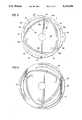
- FIG. 3is a plan view of the geophone spring of this invention.
- FIG. 4is a plan view of an alternate embodiment of the geophone spring of this invention.
- the geophoneshown in FIGS. 1 and 2, includes magnet 10 with pole pieces 12 and 14 positioned at each end. The magnet and its pole pieces are clamped between top 16 and bottom 18 of case 20.
- Coil mass 22includes coil form 22a upon which wire coils 22b and 22c are wrapped. The coil mass is supported for movement relative to the longitudinal axis of the case by diaphragm springs 24 and 26.
- Case top 16is of molded plastic material to reduce the weight of the geophone and to reduce the cost of manufacturing the case top, as compared to the metal case top used in prior art geophones.
- eyelets 28 and 30are embedded in the case top so that they extend outwardly from the case top as shown in FIG. 1.
- the eyeletsare made of electrically conductive material, such as copper.
- Outside terminals 32 and 34also of electrically conductive material, extend through the eyelets and are soldered to the eyelets to seal the annulus between the inside of the eyelets and the outside of the terminals and to electrically connect the terminals to the eyelets. These soldered joints are indicated by the numbers 36 and 38.
- pigtails 40 and 42have one end connected to coil terminals 44 and 46 by solder, which is indicated by the members 48 and 50.
- the other ends of the pigtailsare connected to terminals 32 and 34 also by soldered connections indicated by the numbers 52 and 54.
- the two ends of the wire forming coils 22b and 22care indicated by the numbers 43 and 45 (FIG. 3). They are also connected to terminals 44 and 46 by soldered connections 48 and 50.
- Spring 24The structures of spring spiders 24 and 26 are shown in FIGS. 3 and 4.
- Spring 24will be described first. It includes outer ring 50, inner ring 52 that are connected by three spring arms 54, 56, and 58.
- the spring armsare formed by etching or stamping the spring material in accordance with a predetermined pattern.
- the armsare formed by three grooves 60, 62, and 64. Each groove extends along the outside edge of one of the legs and along the inside edge of the next adjacent leg.
- groove 60extends along the outer edge of arm 54 and along the inner edge of arm 56.
- groove 62extends along the outer edge of arm 56 and the inner edge of arm 58 and groove 64 extends along the outer edge of spring arm 58 and the inner edge of arm 54.
- Each spring armincludes two sections.
- Spring arm 54for example, includes elongated gently curved section 54a and relatively short substantially straight section 54b that increases in width from its juncture with section 54a to its juncture with the inner ring at point A.
- Section 54a of the armis connected to the outer ring at juncture point B.
- the combination of the two sections 54a and 54b to form a generally L-shaped armprovides the desired resistance to lateral forces imposed on the spring and the desired ratio of 20 to 25 to 1 between the spurious resonance of the spring and its natural frequency.
- Spring arms 56 and 58are similarly shaped having elongated gently curved sections 56a and 58a and short straight sections 56b and 58b that increase in width toward their juncture with the inner ring.
- Outer ring 50has sections 59 of increased width opposite each elongated section of the arms to provide more stiffness to the spring at this point to further resist lateral forces.
- One of the important features of the shape of the spring armsare the short substantially straight sections 54b, 56b, and 58b that are positioned so as to better resist bending under the influence of sharp lateral forces that are imposed on the spring because a substantial component of these forces will act to place these sections in longitudinal compression rather than bending.
- the grooves that form the armsalso form relatively wide spaces between the outer ring and the spring arms. These spaces are designed to allow the outer ring to conform as required for the spring mass to engage either the magnet assembly or the housing of the geophone to stop its lateral movement when the geophone is struck a sharp blow from the side. In other words, nothing is going to move but the spring mass and the spring mass can move only a limited distance until it strikes either the magnet assembly or the housing. Therefore, spring spiders that support the coil mass need only allow sufficient lateral movement for the coil mass to strike one of these stops to serve its purpose, which is to absorb this lateral movement without suffering permanent damage.
- the design of the spring as shown in FIGS. 3 and 4accomplishes this result.
- FIG. 4is identical to FIG. 3 except outer ring 50' is much wider, which allows grooves 70, 72, and 74 to be etched in the outer ring between the edge of the outer ring and the portion of the grooves along the outside edge of the arms. This increases the ability of the bottom spring to yield to lateral forces without damage.
Landscapes
- Engineering & Computer Science (AREA)
- Remote Sensing (AREA)
- Physics & Mathematics (AREA)
- Life Sciences & Earth Sciences (AREA)
- Acoustics & Sound (AREA)
- Environmental & Geological Engineering (AREA)
- Geology (AREA)
- General Life Sciences & Earth Sciences (AREA)
- General Physics & Mathematics (AREA)
- Geophysics (AREA)
- Springs (AREA)
Abstract
Description
Claims (12)
Priority Applications (1)
| Application Number | Priority Date | Filing Date | Title |
|---|---|---|---|
| US07/725,198US5134594A (en) | 1991-07-03 | 1991-07-03 | Geophone spring |
Applications Claiming Priority (1)
| Application Number | Priority Date | Filing Date | Title |
|---|---|---|---|
| US07/725,198US5134594A (en) | 1991-07-03 | 1991-07-03 | Geophone spring |
Publications (1)
| Publication Number | Publication Date |
|---|---|
| US5134594Atrue US5134594A (en) | 1992-07-28 |
Family
ID=24913555
Family Applications (1)
| Application Number | Title | Priority Date | Filing Date |
|---|---|---|---|
| US07/725,198Expired - Fee RelatedUS5134594A (en) | 1991-07-03 | 1991-07-03 | Geophone spring |
Country Status (1)
| Country | Link |
|---|---|
| US (1) | US5134594A (en) |
Cited By (33)
| Publication number | Priority date | Publication date | Assignee | Title |
|---|---|---|---|---|
| US5351490A (en)* | 1992-01-31 | 1994-10-04 | Mitsubishi Denki Kabushiki Kaisha | Piston/displacer support means for a cryogenic refrigerator |
| US5450375A (en)* | 1994-07-20 | 1995-09-12 | Shaw Industries Limited | Geophone shock absorber |
| US5469408A (en)* | 1994-07-20 | 1995-11-21 | Shaw Industries Limited | High resolution geophone |
| US5555222A (en)* | 1994-09-26 | 1996-09-10 | Shaw Industries Limited | Low distortion geophone spring |
| US20040021123A1 (en)* | 2000-04-26 | 2004-02-05 | Howell Larry L | Compliant, ortho-planar, linear motion spring |
| US20050014582A1 (en)* | 2000-04-26 | 2005-01-20 | Brigham Young University | Continuously variable transmission or clutch with ortho-planar compliant mechanism |
| US20050240154A1 (en)* | 2004-04-21 | 2005-10-27 | Unomedical A/S: | Infusion set with patch |
| US7115112B2 (en) | 2002-09-02 | 2006-10-03 | Unomedical A/S | Device for subcutaneous administration of a medicament to a patient and tubing for same |
| US7147623B2 (en) | 2002-02-12 | 2006-12-12 | Unomedical A/S | Infusion device with needle shield |
| US7258680B2 (en) | 2002-09-02 | 2007-08-21 | Unomedical A/S | Device for subcutaneous administration of a medicament to a patient |
| USD554253S1 (en) | 2003-10-15 | 2007-10-30 | Unomedical A/S | Medical infusion device |
| USD554491S1 (en)* | 2006-02-08 | 2007-11-06 | Johan Stenberg | Spring |
| GB2444373A (en)* | 2006-11-28 | 2008-06-04 | Nanometrics Inc | Inertial sensor |
| USD576267S1 (en) | 2003-10-15 | 2008-09-02 | Unomedical A/S | Medical infusion device |
| USD579541S1 (en) | 2003-10-15 | 2008-10-28 | Unomedical A/S | Medical insertion device |
| US7481794B2 (en) | 2003-02-12 | 2009-01-27 | Unomedical A/S | Cover |
| US7594909B2 (en) | 2002-09-02 | 2009-09-29 | Unomedical, A/S | Apparatus and method for adjustment of the length of an infusion tubing |
| US7621395B2 (en) | 2005-06-28 | 2009-11-24 | Unomedical A/S | Packing for infusion set and method of applying an infusion set |
| US7648494B2 (en) | 2004-03-26 | 2010-01-19 | Unomedical A/S | Infusion set and injector device for infusion set |
| US7654484B2 (en) | 2002-09-02 | 2010-02-02 | Unomedical A/S | Apparatus for and a method of adjusting the length of an infusion tube |
| US7802824B2 (en) | 2002-11-26 | 2010-09-28 | Unomedical A/S | Connecting piece for a tubing |
| US7867200B2 (en) | 2004-12-10 | 2011-01-11 | Unomedical A/S | Inserter |
| US20110007607A1 (en)* | 2009-07-08 | 2011-01-13 | Geospace Technologies, Lp | Geophone having improved sensitivity |
| US20110007609A1 (en)* | 2009-07-08 | 2011-01-13 | Geospace Technologies, Lp | Vertical geophone having improved distortion characteristics |
| US20110007608A1 (en)* | 2009-07-08 | 2011-01-13 | Geospace Technologies, Lp | Geophone having improved damping control |
| US8062250B2 (en) | 2004-08-10 | 2011-11-22 | Unomedical A/S | Cannula device |
| USD655807S1 (en) | 2005-12-09 | 2012-03-13 | Unomedical A/S | Medical device |
| US8152771B2 (en) | 2001-09-27 | 2012-04-10 | Unomedical A/S | Injector device for placing a subcutaneous infusion set |
| WO2014058472A1 (en)* | 2012-10-11 | 2014-04-17 | Silicon Audio Inc. | Closed loop control techniques for displacement sensors with optical readout |
| US20160146282A1 (en)* | 2013-01-18 | 2016-05-26 | Thales | Suspension element for the mechanical attachment of a load suspended within a mount |
| USD805889S1 (en)* | 2016-03-24 | 2017-12-26 | Flsmidth A/S | Leaf spring |
| US10369277B2 (en) | 2005-09-12 | 2019-08-06 | Unomedical A/S | Invisible needle |
| CN110988983A (en)* | 2019-12-23 | 2020-04-10 | 芯元(浙江)科技有限公司 | Spring piece, detector and seismic exploration system for seismic exploration |
Citations (2)
| Publication number | Priority date | Publication date | Assignee | Title |
|---|---|---|---|---|
| US4623991A (en)* | 1984-11-30 | 1986-11-18 | Geosource, Inc. | Delta-shaped geophone spring |
| US4685094A (en)* | 1984-11-30 | 1987-08-04 | Geosource Inc. | Lateral compliance device for geophone springs |
- 1991
- 1991-07-03USUS07/725,198patent/US5134594A/ennot_activeExpired - Fee Related
Patent Citations (2)
| Publication number | Priority date | Publication date | Assignee | Title |
|---|---|---|---|---|
| US4623991A (en)* | 1984-11-30 | 1986-11-18 | Geosource, Inc. | Delta-shaped geophone spring |
| US4685094A (en)* | 1984-11-30 | 1987-08-04 | Geosource Inc. | Lateral compliance device for geophone springs |
Cited By (50)
| Publication number | Priority date | Publication date | Assignee | Title |
|---|---|---|---|---|
| US5351490A (en)* | 1992-01-31 | 1994-10-04 | Mitsubishi Denki Kabushiki Kaisha | Piston/displacer support means for a cryogenic refrigerator |
| US5450375A (en)* | 1994-07-20 | 1995-09-12 | Shaw Industries Limited | Geophone shock absorber |
| US5469408A (en)* | 1994-07-20 | 1995-11-21 | Shaw Industries Limited | High resolution geophone |
| US5555222A (en)* | 1994-09-26 | 1996-09-10 | Shaw Industries Limited | Low distortion geophone spring |
| US20040021123A1 (en)* | 2000-04-26 | 2004-02-05 | Howell Larry L | Compliant, ortho-planar, linear motion spring |
| US20050014582A1 (en)* | 2000-04-26 | 2005-01-20 | Brigham Young University | Continuously variable transmission or clutch with ortho-planar compliant mechanism |
| US7338398B2 (en) | 2000-04-26 | 2008-03-04 | Brigham Young University | Continuously variable transmission or clutch with ortho-planar compliant mechanism |
| US6983924B2 (en) | 2000-04-26 | 2006-01-10 | Brigham Young University | Compliant, ortho-planar, linear motion spring |
| US8152771B2 (en) | 2001-09-27 | 2012-04-10 | Unomedical A/S | Injector device for placing a subcutaneous infusion set |
| US8162892B2 (en) | 2001-09-27 | 2012-04-24 | Unomedical A/S | Injector device for placing a subcutaneous infusion set |
| US8172805B2 (en) | 2001-09-27 | 2012-05-08 | Unomedical A/S | Injector device for placing a subcutaneous infusion set |
| US7147623B2 (en) | 2002-02-12 | 2006-12-12 | Unomedical A/S | Infusion device with needle shield |
| US7258680B2 (en) | 2002-09-02 | 2007-08-21 | Unomedical A/S | Device for subcutaneous administration of a medicament to a patient |
| US7594909B2 (en) | 2002-09-02 | 2009-09-29 | Unomedical, A/S | Apparatus and method for adjustment of the length of an infusion tubing |
| US7115112B2 (en) | 2002-09-02 | 2006-10-03 | Unomedical A/S | Device for subcutaneous administration of a medicament to a patient and tubing for same |
| US7654484B2 (en) | 2002-09-02 | 2010-02-02 | Unomedical A/S | Apparatus for and a method of adjusting the length of an infusion tube |
| US7802824B2 (en) | 2002-11-26 | 2010-09-28 | Unomedical A/S | Connecting piece for a tubing |
| US7481794B2 (en) | 2003-02-12 | 2009-01-27 | Unomedical A/S | Cover |
| USD579541S1 (en) | 2003-10-15 | 2008-10-28 | Unomedical A/S | Medical insertion device |
| USD576267S1 (en) | 2003-10-15 | 2008-09-02 | Unomedical A/S | Medical infusion device |
| USD554253S1 (en) | 2003-10-15 | 2007-10-30 | Unomedical A/S | Medical infusion device |
| US7648494B2 (en) | 2004-03-26 | 2010-01-19 | Unomedical A/S | Infusion set and injector device for infusion set |
| US8221355B2 (en) | 2004-03-26 | 2012-07-17 | Unomedical A/S | Injection device for infusion set |
| US20050240154A1 (en)* | 2004-04-21 | 2005-10-27 | Unomedical A/S: | Infusion set with patch |
| US8062250B2 (en) | 2004-08-10 | 2011-11-22 | Unomedical A/S | Cannula device |
| US7867200B2 (en) | 2004-12-10 | 2011-01-11 | Unomedical A/S | Inserter |
| US7867199B2 (en) | 2004-12-10 | 2011-01-11 | Unomedical A/S | Inserter |
| US7621395B2 (en) | 2005-06-28 | 2009-11-24 | Unomedical A/S | Packing for infusion set and method of applying an infusion set |
| US10369277B2 (en) | 2005-09-12 | 2019-08-06 | Unomedical A/S | Invisible needle |
| USD682415S1 (en) | 2005-12-09 | 2013-05-14 | Unomedical A/S | Medical device |
| USD655807S1 (en) | 2005-12-09 | 2012-03-13 | Unomedical A/S | Medical device |
| USD554984S1 (en)* | 2006-02-08 | 2007-11-13 | Johan Stenberg | Spring |
| USD554491S1 (en)* | 2006-02-08 | 2007-11-06 | Johan Stenberg | Spring |
| GB2444373A (en)* | 2006-11-28 | 2008-06-04 | Nanometrics Inc | Inertial sensor |
| US20080148851A1 (en)* | 2006-11-28 | 2008-06-26 | Nanometrics Inc. | Inertial sensor |
| GB2444373B (en)* | 2006-11-28 | 2011-08-10 | Nanometrics Inc | Inertial sensor |
| US7594438B2 (en) | 2006-11-28 | 2009-09-29 | Nanometrics Inc. | Inertial sensor having a flexing element supporting a movable mass |
| US20110007609A1 (en)* | 2009-07-08 | 2011-01-13 | Geospace Technologies, Lp | Vertical geophone having improved distortion characteristics |
| US8050144B2 (en) | 2009-07-08 | 2011-11-01 | Geospace Technologies Lp | Vertical geophone having improved distortion characteristics |
| US20110007607A1 (en)* | 2009-07-08 | 2011-01-13 | Geospace Technologies, Lp | Geophone having improved sensitivity |
| US8208347B2 (en) | 2009-07-08 | 2012-06-26 | Geospace Technologies, Lp | Geophone having improved damping control |
| US20110007608A1 (en)* | 2009-07-08 | 2011-01-13 | Geospace Technologies, Lp | Geophone having improved damping control |
| US8098546B2 (en) | 2009-07-08 | 2012-01-17 | Geospace Technologies, Lp | Geophone having improved sensitivity |
| WO2014058472A1 (en)* | 2012-10-11 | 2014-04-17 | Silicon Audio Inc. | Closed loop control techniques for displacement sensors with optical readout |
| US9702992B2 (en) | 2012-10-11 | 2017-07-11 | Silicon Audio Seismic, LLC | Closed loop control techniques for displacement sensors with optical readout |
| CN104884915A (en)* | 2012-10-11 | 2015-09-02 | 硅音震有限公司 | Closed loop control techniques for displacement sensors with optical readout |
| US20160146282A1 (en)* | 2013-01-18 | 2016-05-26 | Thales | Suspension element for the mechanical attachment of a load suspended within a mount |
| US10337578B2 (en)* | 2013-01-18 | 2019-07-02 | Thales | Suspension element for the mechanical attachment of a load suspended within a mount |
| USD805889S1 (en)* | 2016-03-24 | 2017-12-26 | Flsmidth A/S | Leaf spring |
| CN110988983A (en)* | 2019-12-23 | 2020-04-10 | 芯元(浙江)科技有限公司 | Spring piece, detector and seismic exploration system for seismic exploration |
Similar Documents
| Publication | Publication Date | Title |
|---|---|---|
| US5134594A (en) | Geophone spring | |
| US4623991A (en) | Delta-shaped geophone spring | |
| US4685094A (en) | Lateral compliance device for geophone springs | |
| US5450375A (en) | Geophone shock absorber | |
| US5134593A (en) | Geophone spring | |
| US7505369B2 (en) | Geophone with mass position sensing | |
| US4323994A (en) | Geophone spring | |
| EP0771427B1 (en) | High resolution geophone | |
| US4285054A (en) | Geophone | |
| US3738445A (en) | Seismometer spring suspension system | |
| US8050144B2 (en) | Vertical geophone having improved distortion characteristics | |
| JP2005522667A (en) | Geophone and geophone manufacturing method | |
| US2748370A (en) | Seismometer | |
| US4504932A (en) | Geophone having a non-conductive coilform | |
| US3582875A (en) | Geophone device | |
| US5555222A (en) | Low distortion geophone spring | |
| US3878504A (en) | Damped geophone | |
| US3412376A (en) | Low-frequency seismometer | |
| US3451040A (en) | Spring suspension for a low-frequency geophone | |
| US2788511A (en) | Lightweight seismometer | |
| EP1249714A2 (en) | Double-ended geophone | |
| JPH075884A (en) | Mounting device | |
| GB2318019A (en) | Geophone shock absorber | |
| CA1281408C (en) | Variflux vibration transducer | |
| WO2020023891A1 (en) | Omni-directional geophone with 10 hertz natural frequency |
Legal Events
| Date | Code | Title | Description |
|---|---|---|---|
| AS | Assignment | Owner name:SHAW INDUSTRIES LTD. A CORP. OF CANADA, CANADA Free format text:ASSIGNMENT OF ASSIGNORS INTEREST.;ASSIGNOR:WOO, DANIEL M.;REEL/FRAME:005822/0594 Effective date:19910828 | |
| FEPP | Fee payment procedure | Free format text:PAYOR NUMBER ASSIGNED (ORIGINAL EVENT CODE: ASPN); ENTITY STATUS OF PATENT OWNER: LARGE ENTITY | |
| FPAY | Fee payment | Year of fee payment:4 | |
| FPAY | Fee payment | Year of fee payment:8 | |
| AS | Assignment | Owner name:SERCEL INC., TEXAS Free format text:ASSIGNMENT OF ASSIGNORS INTEREST;ASSIGNOR:SHAW INDUSTRIES LTD.;REEL/FRAME:011627/0056 Effective date:20000922 | |
| REMI | Maintenance fee reminder mailed | ||
| LAPS | Lapse for failure to pay maintenance fees | ||
| FP | Lapsed due to failure to pay maintenance fee | Effective date:20040728 | |
| AS | Assignment | Owner name:CREDIT SUISSE, CAYMAN ISLANDS BRANCH, AS COLLATERA Free format text:SECURITY AGREEMENT;ASSIGNORS:SERCEL, INC.;VOLNAY ACQUISITION CO. II;REEL/FRAME:018923/0499 Effective date:20070112 Owner name:CREDIT SUISSE, AS COLLATERAL AGENT, NEW YORK Free format text:SECURITY AGREEMENT;ASSIGNORS:SERCEL, INC.;CGGVERITAS SERVICES INC. (F/K/A VOLNAY ACQUISITION CO. II);REEL/FRAME:018923/0586 Effective date:20070207 | |
| AS | Assignment | Owner name:CREDIT SUISSE, LONDON BRANCH, AS SECOND LIEN COLLA Free format text:SECURITY AGREEMENT;ASSIGNORS:SERCEL, INC.;VOLNAY ACQUISITION CO. II;REEL/FRAME:018923/0611 Effective date:20070112 | |
| AS | Assignment | Owner name:SERCEL, INC., TEXAS Free format text:RELEASE OF SECURITY AGREEMENT;ASSIGNOR:CREDIT SUISSE AG, LONDON BRANCH, AS COLLATERAL AGENT;REEL/FRAME:031051/0062 Effective date:20130718 Owner name:CGG HOLDING (U.S.) INC. (F/K/A CGG VERITAS SERVICE Free format text:RELEASE OF SECURITY AGREEMENT;ASSIGNOR:CREDIT SUISSE AG, LONDON BRANCH, AS COLLATERAL AGENT;REEL/FRAME:031051/0062 Effective date:20130718 | |
| AS | Assignment | Owner name:CGG HOLDING (U.S.) INC. (F/K/A CGG VERITAS SERVICE Free format text:RELEASE OF SECURITY AGREEMENT;ASSIGNOR:CREDIT SUISSE AG, CAYMAN ISLANDS BRANCH, AS COLLATERAL AGENT;REEL/FRAME:031059/0186 Effective date:20130718 Owner name:SERCEL, INC., TEXAS Free format text:RELEASE OF SECURITY AGREEMENT;ASSIGNOR:CREDIT SUISSE AG, CAYMAN ISLANDS BRANCH, AS COLLATERAL AGENT;REEL/FRAME:031059/0186 Effective date:20130718 | |
| STCH | Information on status: patent discontinuation | Free format text:PATENT EXPIRED DUE TO NONPAYMENT OF MAINTENANCE FEES UNDER 37 CFR 1.362 |