US5134347A - Low power consumption wireless data transmission and control system - Google Patents
Low power consumption wireless data transmission and control systemDownload PDFInfo
- Publication number
- US5134347A US5134347AUS07/777,059US77705991AUS5134347AUS 5134347 AUS5134347 AUS 5134347AUS 77705991 AUS77705991 AUS 77705991AUS 5134347 AUS5134347 AUS 5134347A
- Authority
- US
- United States
- Prior art keywords
- time
- electrical power
- predetermined period
- packet
- timed signals
- Prior art date
- Legal status (The legal status is an assumption and is not a legal conclusion. Google has not performed a legal analysis and makes no representation as to the accuracy of the status listed.)
- Expired - Lifetime
Links
- 230000005540biological transmissionEffects0.000titleclaimsabstractdescription11
- 230000004044responseEffects0.000claimsdescription8
- 238000005070samplingMethods0.000claimsdescription5
- 230000008901benefitEffects0.000description3
- 238000000034methodMethods0.000description2
- 230000004048modificationEffects0.000description2
- 238000012986modificationMethods0.000description2
- 238000011282treatmentMethods0.000description2
- 230000004913activationEffects0.000description1
- 238000004364calculation methodMethods0.000description1
- 238000004590computer programMethods0.000description1
- 238000010276constructionMethods0.000description1
- 230000008878couplingEffects0.000description1
- 238000010168coupling processMethods0.000description1
- 238000005859coupling reactionMethods0.000description1
- 230000009849deactivationEffects0.000description1
- 230000003247decreasing effectEffects0.000description1
- 230000001419dependent effectEffects0.000description1
- 238000010586diagramMethods0.000description1
- 230000005669field effectEffects0.000description1
- 229910044991metal oxideInorganic materials0.000description1
- 150000004706metal oxidesChemical class0.000description1
- 230000009467reductionEffects0.000description1
- 230000008439repair processEffects0.000description1
- 239000004065semiconductorSubstances0.000description1
Images


Classifications
- G—PHYSICS
- G08—SIGNALLING
- G08C—TRANSMISSION SYSTEMS FOR MEASURED VALUES, CONTROL OR SIMILAR SIGNALS
- G08C17/00—Arrangements for transmitting signals characterised by the use of a wireless electrical link
- H—ELECTRICITY
- H04—ELECTRIC COMMUNICATION TECHNIQUE
- H04W—WIRELESS COMMUNICATION NETWORKS
- H04W52/00—Power management, e.g. Transmission Power Control [TPC] or power classes
- H04W52/02—Power saving arrangements
- H04W52/0209—Power saving arrangements in terminal devices
- H04W52/0261—Power saving arrangements in terminal devices managing power supply demand, e.g. depending on battery level
- H04W52/0274—Power saving arrangements in terminal devices managing power supply demand, e.g. depending on battery level by switching on or off the equipment or parts thereof
- H04W52/028—Power saving arrangements in terminal devices managing power supply demand, e.g. depending on battery level by switching on or off the equipment or parts thereof switching on or off only a part of the equipment circuit blocks
- H04W52/0283—Power saving arrangements in terminal devices managing power supply demand, e.g. depending on battery level by switching on or off the equipment or parts thereof switching on or off only a part of the equipment circuit blocks with sequential power up or power down of successive circuit blocks, e.g. switching on the local oscillator before RF or mixer stages
- E—FIXED CONSTRUCTIONS
- E06—DOORS, WINDOWS, SHUTTERS, OR ROLLER BLINDS IN GENERAL; LADDERS
- E06B—FIXED OR MOVABLE CLOSURES FOR OPENINGS IN BUILDINGS, VEHICLES, FENCES OR LIKE ENCLOSURES IN GENERAL, e.g. DOORS, WINDOWS, BLINDS, GATES
- E06B9/00—Screening or protective devices for wall or similar openings, with or without operating or securing mechanisms; Closures of similar construction
- E06B9/56—Operating, guiding or securing devices or arrangements for roll-type closures; Spring drums; Tape drums; Counterweighting arrangements therefor
- E06B9/68—Operating devices or mechanisms, e.g. with electric drive
- Y—GENERAL TAGGING OF NEW TECHNOLOGICAL DEVELOPMENTS; GENERAL TAGGING OF CROSS-SECTIONAL TECHNOLOGIES SPANNING OVER SEVERAL SECTIONS OF THE IPC; TECHNICAL SUBJECTS COVERED BY FORMER USPC CROSS-REFERENCE ART COLLECTIONS [XRACs] AND DIGESTS
- Y02—TECHNOLOGIES OR APPLICATIONS FOR MITIGATION OR ADAPTATION AGAINST CLIMATE CHANGE
- Y02D—CLIMATE CHANGE MITIGATION TECHNOLOGIES IN INFORMATION AND COMMUNICATION TECHNOLOGIES [ICT], I.E. INFORMATION AND COMMUNICATION TECHNOLOGIES AIMING AT THE REDUCTION OF THEIR OWN ENERGY USE
- Y02D30/00—Reducing energy consumption in communication networks
- Y02D30/70—Reducing energy consumption in communication networks in wireless communication networks
- Y—GENERAL TAGGING OF NEW TECHNOLOGICAL DEVELOPMENTS; GENERAL TAGGING OF CROSS-SECTIONAL TECHNOLOGIES SPANNING OVER SEVERAL SECTIONS OF THE IPC; TECHNICAL SUBJECTS COVERED BY FORMER USPC CROSS-REFERENCE ART COLLECTIONS [XRACs] AND DIGESTS
- Y10—TECHNICAL SUBJECTS COVERED BY FORMER USPC
- Y10S—TECHNICAL SUBJECTS COVERED BY FORMER USPC CROSS-REFERENCE ART COLLECTIONS [XRACs] AND DIGESTS
- Y10S388/00—Electricity: motor control systems
- Y10S388/923—Specific feedback condition or device
- Y10S388/933—Radiant energy responsive device
Definitions
- This inventionrelates to a low power consumption wireless data transmission and control system and, more particularly, to a data control system having a stored computer program and which is effective to receive remotely transmitted shade commands and to articulate a shade in response to the received commands while consuming a relatively small amount of electrical power during times at which no commands are transmitted.
- Battery powered devicesare used in many applications to control many types of devices or apparatuses, such as shades, in response to remotely transmitted command signals. These signals are of such types as electro-optical, electro-magnetic, and/or sonic frequency signals.
- a control systemwhich contains a microprocessor under stored program control.
- the microprocessorselectively energizes the system at selected intervals of time effective to allow the system to receive a transmitted signal while reducing the power consumed by the system during times in which no transmitted command signals exists. These selected intervals of time are dependent, in part, upon the characteristics of the waveform of the command signal and may be modifiable within the stored program.
- FIG. 1is a block diagram of a data transmission and control system made in accordance with the teachings of the preferred embodiment of this invention and effective to articulate a shade in response to remotely transmitted command signals;
- FIG. 2is an illustration of typical packets of data which are utilized by the system of this invention.
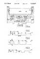
- FIG. 3is an illustration of signals comprising the packets shown in FIG. 2;
- FIG. 4is an illustration of alternate types of signals which may be used to comprise the packets shown in FIG. 2;
- FIG. 5is a flow chart showing the general sequence of steps associated with the stored program within the system of this invention.
- FIG. 6shows the general sequence of steps comprising the "sleep" step of FIG. 5;
- FIGS. 7(a)-(c)shows the sequence of steps comprising the "Look” step of FIG. 5;
- FIG. 8is a graph showing the power consumed by the system of the preferred embodiment of this invention while in the "Sleep” step and in the "Look” step of FIG. 5;
- FIG. 9is a graph showing the relationship between average power usage and the wait time associated with the system of the preferred embodiment of this invention.
- FIG. 10is a graph showing the relationship between command recognition latency time and wait time associated with the data transmission and control system made in accordance with the teachings of the preferred embodiment of this invention.
- system 10data transmission and control system (i.e. "system") 10, made in accordance with the teachings of the preferred embodiment of this invention, and used to selectively articulate shade 24 in response to a received command signal 14.
- system 10includes a signal reception element 12 which receives the remotely transmitted wireless command signal 14 from a transmitter 16 and which outputs an electrical signal to a receiver/detector 18 in response to this received command.
- the detector 18effectively demodulates the command 14 and transmits electrical control signals to the microprocessor 26. These signals are effective to cause microprocessor 26 to activate the motor 20 such that the shade or window covering 24 is moved, by the use of rollers 22, in a manner consistent with or set forth by the received signal 14. Electrical power is provided to the receiver 18 by the battery 34.
- Microprocessor 26is under stored programmed control and is effective to "de-activate” or reduce the amount of electrical power utilized by detector 18 for a predetermined period of time.
- microprocessor 26comprises a Motorola model MC68HC705C8 microcontroller.
- the coupling of microprocessor 26 and detector 18is achieved through the metal oxide semi-conductor Field effect transistors (MOSFETS) 28 and 30.
- MOSFET 28selectively couples substantially all of the capacitive elements 32 of the detector 18 to electrical ground while MOSFET 30 selectively couples detector 18 to electrical ground.
- MOSFETS 28 and 30are selectively activated only upon receipt of appropriate electronic signals from microprocessor 26.
- Battery 34also provides electrical power to both motor 20 and to microprocessor 26.
- MOSFETS 28 and 30each comprise a Harris model RFD14N05L power MOSFETS while detector 18 comprises a NEC model ⁇ PC1490HA integrated circuit type processor.
- command signal 14is comprised of a series of sequentially positioned packets of data 36.
- Each data packet 36has a unique time at which it was transmitted. The total transmission time associated with each of the packets 36 varies from a maximum transmission time 38 to a minimum time 40.
- Each packet 36is further made to be transmitted only at equally spaced timing intervals 41.
- each of the packets 36contains a series of sequentially transmitted signals 42 each having either a minimum period 44 representing a logical value of zero or a maximum period 46 representing a logical value of one.
- the stored programdetermines and/or selects the times at which the detector 18 is allowed to be energized. This selection and/or determination is made by causing the microprocessor 26 to undergo a series of operational steps which are illustrated in flow chart 48 of FIG. 5.
- microprocessor 26performs a start operation 50 and a reset operation 52 in which all of the variables contained within the microprocessor 26 are made to be a logically known state.
- Initialization step 54follows step 52, in which microprocessor 26 prepares for receiver deactivation while ensuring that subsequent settle times are minimized and also determines the address of system 10.
- Step 54is then followed by step 55 in which the microprocessor 26 deactivates the detector 18 for a predetermined period of time in order to reduce the amount of electrical power consumed by detector 18.
- Step 56follows step 55 in which the microprocessor 26 activates the detector 18 for a predetermined amount of time in order to determine if a command signal 14 has been transmitted.
- Step 56is then followed by step 58 or by step 55.
- step 56the microprocessor 26 enters step 58 in which the detector 18 is allowed to decode the received transmitted data packets 36. If a command 14 is not received while the microprocessor 26 is in step 56, then the microprocessor 26 deactivates the detector 18 for a predetermined period of time in accordance with step 55. Steps 55, 56 and 58 are continually traversed by the microprocessor 26 until the stored program is modified or until a system fault occurs.
- the Sleep step 55comprises a step 60 in which the microprocessor 26 de-energizes MOSFET 28, effective to disconnect capacitive elements 32 from ground. Step 60 is then followed by step 62 in which the microprocessor 26 de-energizes MOSFET 30, effective to disconnect the detector 18 from an electrical ground and thereby preventing the flow of electrical power to the detector 18.
- Step 62is then followed by step 64 in which the microprocessor 26 enters a low power wait state for a predetermined period of time.
- This predetermined period of timein the preferred embodiment of this invention, is made to be the longest amount of time that the detector 18 may be deactivated while still ensuring that substantially every transmitted command 14, destined for detector 18, is received and recognized. The longer that this time becomes, the more electrical power that is conserved.
- the predetermined period of time of step 64may be calculated by subtracting both the settling time of elements 32 and two of the periods 44 from period 40. In the preferred embodiment of this invention, the predetermined time of step 64 is approximately 18.289 milliseconds. It should be noted that this predetermined amount of time will vary depending upon the number of edges 66, required by the stored program, to be received in order to receive and recognize packet 36. In the preferred embodiment of this invention, three separate edges 66 must be received before the microprocessor 26 determines that a command is present. The use of such edges 66 will be explained in greater detail later.
- the predetermined time of step 64will decrease by an amount equal to the number of required edges multiplied by the time associated with period 46. Consequently, less power is conserved if more edges 66 are used to detect the occurrence of a packet 36.
- step 56the microprocessor 26 initially enters a step 68 in which the MOSFET 30 is activated, thereby allowing the detector 18 to be re-coupled to electrical ground and also allowing electrical power to be transmitted to the detector 18 by the battery 34.
- Step 68is then followed by step 70 in which microprocessor 26 activates the MOSFET 28 thereby allowing the elements 32 to also be re-coupled to electrical ground. Since the elements 32 were previously de-coupled from electrical ground before the detector 18 was deactivated, the electrical charge contained upon these capacitive elements 32 is now still substantially similar to the charge that was present before the capacitive elements 32 were de-coupled from electrical ground.
- the settling time in the preferred embodiments of this inventionis approximately 0.7 milliseconds. It should be noted that it is best to reconnect the elements 32 only after detector 18 is activated in order to further ensure a reduced settling time.
- Step 72is then followed by step 74 in which the detector 18 is activated (i.e. allowed to sense the occurrence of transmitted signals) and is looking for first edge 66 for a predetermined period of time.
- This predetermined period of timeis made to be substantially equal to period 46. In the preferred embodiment of this invention, this predetermined period of time is actually made to be approximately 10% greater than period 46 in order to allow for the receipt of signals 14 which are be shifted in position by noise.
- Step 74is then followed by step 76 in which the microprocessor 26 determines if a first edge 66 had been received during this first predetermined period of time.
- Microprocessor 26enters step 55 if no edge 66 has been received in step 74, while alternatively entering step 78 if one edge 66 has been received during step 74.
- step 78the microprocessor 26 records the time at which this first edge 66 has been received.
- step 80the microprocessor 26 saves this edge receipt time and records this as a "prior edge time”.
- Step 80is then followed by step 82 in which the microprocessor 26 looks for a second and different edge 66 for a second predetermined period of time.
- this second predetermined period of timeis substantially the same as the first predetermined period of time associated with step 74.
- Step 82is then followed by step 84 in which the microprocessor 26 determines if a second and different edge 66 has been received during this second predetermined period of time. If, in step 84, the microprocessor 26 determines that this second edge 66 has not been received, then step 84 is followed by step 55.
- Microprocessor 26enters step 86 if a second edge 66 has been received during step 84 and, in step 84, records the time at which the second edge was received.
- step 86the microprocessor 26 determines the time between the receipt of the two edges 66. The validity of this measured time is then determined in step 88 by comparing the elapsed time between the receipt of the two edges 66 with each of the periods 44 and 46. In the preferred embodiment of this invention, the comparison is made by the use of period values which are within approximately 10% of the actual values of periods 44 and 46.
- Microprocessor 26enters step 55 if the elapsed time does not substantially equal one of the periods 44 and 46. In step 55 microprocessor 26 deactivates receiver 18 for a period of time since no commands 14 are present.
- step 88is followed by step 90 in which the microprocessor 26 saves or stores the second edge time as the "prior edge time”.
- step 90is then followed by step 92 in which the microprocessor 26 looks for a third and different edge 66 for a third predetermined period of time.
- this third predetermined period of timeis substantially equal to the predetermined periods of time associated with steps 82 and 74.
- step 92is then followed by step 94 in which the receiver determines if a third edge 66 has been received during this third predetermined period of time.
- step 94determines, in step 94, that a third edge has not been received, then step 94 is followed by step 55.
- Microprocessor 26enters step 96 if a third edge 66 has been received during step 94 and determines the elapsed time between the receipt of the second and third edges 66 while also recording the time at which the third edge has been received. The validity of this elapsed time is determined in step 98 in substantially the same manner as was done in step 88. If the microprocessor 26 determines that this elapsed time is not valid, then microprocessor 26 enters step 55. If this time is valid, microprocessor 26 enters step 100.
- microprocessor 26sets forth a predetermined period of time in which the receiver 18 is to be activated in order that it may receive at least two packets of data 36.
- this timeis made to be the longest amount of time necessary for receiver 18 to receive two additional packets 36 in addition to the packet 36 containing the three sampled edges 66.
- this predetermined period of timewas calculated to be approximately 170 milliseconds. This calculation was made by noting that each of the packets 36 must occur at the start of an interval 41, which in the preferred embodiment of this invention is approximately 67.516 milliseconds. If the three edges 66 used to activate detector 18 occurred at the beginning of a packet 36, a maximum amount of activation time would therefore be required. In this scenario, the receiver 18 would need to be activated for an amount of time equal to substantially two of the intervals 41 in addition to the time associated with a single period 38 (i.e., assuming the second received packet 36 was the longest allowable packet).
- Step 100is then followed by step 102 in which the microprocessor 26 activates the detector 18 for the predetermined period of time as set forth in step 100.
- Step 102is then followed by step 104 in which the microprocessor 26 determines if a command 14 has been received during this predetermined period of time.
- Microprocessor 26in fact, continually checks to see if this time has elapsed without receipt of a command, as shown in step 106. If a command 14 is not received during this time, microprocessor 26 is made to enter step 55 and deactivates the receiver 18 for a predetermined period of time.
- Microprocessor 26enters step 108 if a command is received during step 104 and parses the address of the command 14 before entering step 110.
- step 110the microprocessor 26 compares the parsed command address with the receiver's own address. Step 110 is then followed by step 112 in which the microprocessor 26 determines if the two addresses are the same. If these addresses are not the same, then step 112 is followed 55. If the addresses are the same, then the received command 14 is appropriately decoded in step 58 and the shade 24 is articulated in a manner specified by the received command 14.
- the detector 18is selectively energized only for predetermined intervals of time and only when there is a high probability that a transmitted packet 36 exists. This selective energization of the receiver 18 allows for the saving of electrical power while ensuring that substantially all transmitted commands 14 are received.
- FIG. 8there is shown graph 114 illustrating the electrical current used by the system 10 over a representative period of time. Specifically, it can be seen that the current used by the system 10 when the detector 18 is activated is approximately 2.5 milli-amps and that this amperage will be continuously consumed if the detector 18 is continuously activated.
- the power expendedis reduced to a level below approximately 0.5 milli-amps and rises only to this relatively high level of 2.5 milli-amps when the detector 18 is actually energized. Therefore, the average power expended by the system 10 of this invention (as shown by curve 118) is substantially lower than that expended by past continuously activated controller, as shown by curve 116.
- this average power usagemay be further decreased with a concomitant increase in wait time. That is, the longer that the microprocessor 26 allows the detector 18 to become deactivated (or in a "wait" state), the lower will be the average power usage. However, as shown in curve 122 of FIG. 10, an increase in wait time will cause the detector 18 to lose or to not receive some of this transmitted command signals 14. Therefore, there will be a concomitant increase in command recognition latency time as the wait time is increased. This trade off between average power usage and latency time may be adjusted to any of an infinite number of conditions by appropriately modifying the software contained in the microprocessor 26.
- system 10 of this inventionmay also be employed with packets 36 comprised of a single signal 124, as best shown in FIG. 4. Since each signal has only a single period 126, the microprocessor 26 may be made to simply look for the receipt of a single edge 128 and then, upon receipt of this single edge, cause the detector 18 to be activated for a period of time substantially equal to double the period 126.
Landscapes
- Engineering & Computer Science (AREA)
- Computer Networks & Wireless Communication (AREA)
- Signal Processing (AREA)
- Physics & Mathematics (AREA)
- General Physics & Mathematics (AREA)
- Selective Calling Equipment (AREA)
Abstract
Description
Claims (4)
Priority Applications (1)
| Application Number | Priority Date | Filing Date | Title |
|---|---|---|---|
| US07/777,059US5134347A (en) | 1991-02-22 | 1991-10-16 | Low power consumption wireless data transmission and control system |
Applications Claiming Priority (2)
| Application Number | Priority Date | Filing Date | Title |
|---|---|---|---|
| US07/660,379US5081402A (en) | 1991-02-22 | 1991-02-22 | Low power consumption wireless data transmission and control system |
| US07/777,059US5134347A (en) | 1991-02-22 | 1991-10-16 | Low power consumption wireless data transmission and control system |
Related Parent Applications (1)
| Application Number | Title | Priority Date | Filing Date |
|---|---|---|---|
| US07/660,379DivisionUS5081402A (en) | 1991-02-22 | 1991-02-22 | Low power consumption wireless data transmission and control system |
Publications (1)
| Publication Number | Publication Date |
|---|---|
| US5134347Atrue US5134347A (en) | 1992-07-28 |
Family
ID=27098075
Family Applications (1)
| Application Number | Title | Priority Date | Filing Date |
|---|---|---|---|
| US07/777,059Expired - LifetimeUS5134347A (en) | 1991-02-22 | 1991-10-16 | Low power consumption wireless data transmission and control system |
Country Status (1)
| Country | Link |
|---|---|
| US (1) | US5134347A (en) |
Cited By (67)
| Publication number | Priority date | Publication date | Assignee | Title |
|---|---|---|---|---|
| DE9214850U1 (en)* | 1992-11-02 | 1994-03-03 | Kehren, Clemens, 40667 Meerbusch | Radio message receiving unit |
| US5329213A (en)* | 1991-10-28 | 1994-07-12 | Orton Kevin R | Method of turning off the receiver of a radio controlled model |
| US5517094A (en)* | 1993-07-20 | 1996-05-14 | Harmonic Design, Inc. | Head rail-mounted mini-blind actuator |
| US5675487A (en)* | 1995-06-06 | 1997-10-07 | Iowa State University Research Foundation, Inc. | System for controlling energy through window |
| US5698958A (en)* | 1993-06-11 | 1997-12-16 | Harmonic Design, Inc. | Head rail-mounted actuator for window coverings |
| US5760558A (en)* | 1995-07-24 | 1998-06-02 | Popat; Pradeep P. | Solar-powered, wireless, retrofittable, automatic controller for venetian blinds and similar window converings |
| US5818183A (en)* | 1994-12-06 | 1998-10-06 | Auto-Tilt Enterprises, Ltd. | Blind tilt controller |
| US5909093A (en)* | 1996-11-13 | 1999-06-01 | Hunter Douglas International N.V. | Remotely controlled blind arrangement |
| US5990646A (en)* | 1996-09-06 | 1999-11-23 | Hunter Douglas Inc. | Remotely-controlled battery powered-window covering having power saving receiver |
| EP0843068A3 (en)* | 1996-11-13 | 1999-12-01 | Hunter Douglas Industries B.V. | Remotely controlled blind arrangement |
| WO1999065372A1 (en)* | 1998-06-17 | 1999-12-23 | C.A.S. Locks, S.L. | Distance-controlled electrically powered unit for actuating rail-mounted curtains |
| US6060852A (en)* | 1993-06-11 | 2000-05-09 | Harmonic Design, Inc. | Head rail-mounted actuator for window covering |
| US6369530B2 (en) | 1996-09-06 | 2002-04-09 | Hunter Douglas Inc. | Battery-powered wireless remote-control motorized window covering assembly having controller components |
| US20020130692A1 (en)* | 1999-06-28 | 2002-09-19 | Broadcom Corporation | Current-controlled CMOS logic family |
| US6484069B2 (en)* | 2000-01-31 | 2002-11-19 | Turnils Ab | Awning assembly and control system |
| US20020190770A1 (en)* | 1999-06-28 | 2002-12-19 | Broadcom Corporation | Current -controlled CMOS circuit using higher voltage supply in low voltage CMOS process |
| US20030051080A1 (en)* | 1991-10-01 | 2003-03-13 | Mahany Ronald L. | Radio frequency local area network |
| US20030067337A1 (en)* | 1999-06-28 | 2003-04-10 | Broadcom Corporation | Current-controlled CMOS circuit using higher voltage supply in low voltage CMOS process |
| US20030078006A1 (en)* | 1988-08-04 | 2003-04-24 | Mahany Ronald L. | Remote radio data communication system with data rate switching |
| US20030112767A1 (en)* | 1991-10-01 | 2003-06-19 | Meier Robert C. | Communication network providing wireless and hard-wired dynamic routing |
| US20030122603A1 (en)* | 2000-02-24 | 2003-07-03 | Broadcom Corporation | Current-controlled CMOS circuits with inductive broadbanding |
| US20030174764A1 (en)* | 1989-08-03 | 2003-09-18 | Mahany Ronald L. | Radio frequency communication network having adaptive communication parameters |
| US20040023651A1 (en)* | 1991-05-13 | 2004-02-05 | Gollnick Charles D. | Network supporting roaming, sleeping terminals |
| US20040056717A1 (en)* | 2001-10-25 | 2004-03-25 | Broadcom Corporation | Current-controlled CMOS wideband data amplifier circuits |
| US20040207040A1 (en)* | 2001-05-17 | 2004-10-21 | Broadcom Corporation | Layout technique for C3MOS inductive broadbanding |
| US20040217777A1 (en)* | 1999-06-28 | 2004-11-04 | Armond Hairapetian | Universal single-ended parallel bus |
| US6826165B1 (en) | 1991-10-01 | 2004-11-30 | Broadcom Corporation | Radio frequency local area network |
| US20050072532A1 (en)* | 2003-10-01 | 2005-04-07 | Toby Holden | Self-powered motorized window awning |
| US20060015655A1 (en)* | 2002-08-30 | 2006-01-19 | Zur Uri E | Method and system for supporting read operations with CRC for iSCSI and iSCSI chimney |
| US20080025315A1 (en)* | 2002-03-08 | 2008-01-31 | Broadcom Corporation | System and method for identifying upper layer protocol message boundaries |
| US20080088269A1 (en)* | 2006-10-11 | 2008-04-17 | Kazuo Katsuyama | Motor Controller |
| US7362174B2 (en) | 2005-07-29 | 2008-04-22 | Broadcom Corporation | Current-controlled CMOS (C3MOS) wideband input data amplifier for reduced differential and common-mode reflection |
| US20080095182A1 (en)* | 2002-08-30 | 2008-04-24 | Uri Elzur | System and method for tcp/ip offload independent of bandwidth delay product |
| US20080151922A1 (en)* | 2002-08-30 | 2008-06-26 | Uri Elzur | System and method for tcp offload |
| US7415548B2 (en) | 1991-05-13 | 2008-08-19 | Broadcom Corporation | Communication network having a plurality of bridging nodes which transmits a polling message with backward learning technique to determine communication pathway |
| US20080223951A1 (en)* | 2007-02-23 | 2008-09-18 | Great Stuff, Inc. | Remote control for valve and hose reel system |
| US20080298369A1 (en)* | 2002-08-30 | 2008-12-04 | Uri Elzur | System and method for handling out-of-order frames |
| US20090092070A1 (en)* | 1992-11-02 | 2009-04-09 | Broadcom Corporation | Radio frequency local area network |
| US7598811B2 (en) | 2005-07-29 | 2009-10-06 | Broadcom Corporation | Current-controlled CMOS (C3MOS) fully differential integrated wideband amplifier/equalizer with adjustable gain and frequency response without additional power or loading |
| US7598788B2 (en) | 2005-09-06 | 2009-10-06 | Broadcom Corporation | Current-controlled CMOS (C3MOS) fully differential integrated delay cell with variable delay and high bandwidth |
| US20090254647A1 (en)* | 2002-08-29 | 2009-10-08 | Uri Elzur | System and method for network interfacing |
| US7640351B2 (en) | 2005-11-04 | 2009-12-29 | Intermatic Incorporated | Application updating in a home automation data transfer system |
| EP2145689A1 (en) | 2008-07-16 | 2010-01-20 | VLN Advanced Technologies Inc. | Method and apparatus for prepping surfaces with a high-frequency forced pulsed waterjet |
| US7694005B2 (en) | 2005-11-04 | 2010-04-06 | Intermatic Incorporated | Remote device management in a home automation data transfer system |
| US7698448B2 (en) | 2005-11-04 | 2010-04-13 | Intermatic Incorporated | Proxy commands and devices for a home automation data transfer system |
| US7870232B2 (en) | 2005-11-04 | 2011-01-11 | Intermatic Incorporated | Messaging in a home automation data transfer system |
| US20110110236A1 (en)* | 2001-07-23 | 2011-05-12 | Shiri Kadambi | Multiple Logical Channels for Use in Network Devices |
| US8132592B2 (en) | 2003-03-13 | 2012-03-13 | Great Stuff, Inc. | Remote control for hose operation |
| US20120125543A1 (en)* | 2010-09-17 | 2012-05-24 | Lutron Electronics Co., Inc. | Motorized Venetian Blind System |
| US20120216462A1 (en)* | 2011-02-24 | 2012-08-30 | CIW Enterprises | Method For Vertical Acting Egress And Fire/Smoke Protection |
| WO2012125414A3 (en)* | 2011-03-11 | 2013-01-03 | Lutron Electronics Co., Inc. | Motorized window treatment |
| US20130228289A1 (en)* | 2011-02-24 | 2013-09-05 | Ciw Enterprises, Inc | Fire and Smoke Rated Fabric Door |
| US20130263510A1 (en)* | 2010-12-16 | 2013-10-10 | Romain Gassion | Method for the individualized and automated control of the means for closing off at least one window, control assembly for implementing said method, and parameter-setting tool for said assembly |
| US20130276371A1 (en)* | 2011-01-06 | 2013-10-24 | Koninklijke Philips N.V. | Ambient light control |
| US8750320B2 (en) | 1997-01-23 | 2014-06-10 | Broadcom Corporation | Fibre channel arbitrated loop bufferless switch circuitry to increase bandwidth without significant increase in cost |
| US8798091B2 (en) | 1998-11-19 | 2014-08-05 | Broadcom Corporation | Fibre channel arbitrated loop bufferless switch circuitry to increase bandwidth without significant increase in cost |
| JP2014218853A (en)* | 2013-05-09 | 2014-11-20 | 文化シヤッター株式会社 | Open/close device |
| US9047758B2 (en) | 2013-03-14 | 2015-06-02 | Dometic Corporation | Solar powered energy module |
| US9115537B2 (en) | 2013-02-15 | 2015-08-25 | Lutron Electronics Co., Inc. | Battery-powered roller shade system |
| US20160123076A1 (en)* | 2014-11-01 | 2016-05-05 | Lutron Electronics Co., Inc. | Interlocking pivotable fascia for motorized window treatment |
| WO2016096215A1 (en)* | 2014-12-15 | 2016-06-23 | Robert Bosch Gmbh | Liquid jet cutting method |
| US9488000B2 (en) | 2013-04-15 | 2016-11-08 | Lutron Electronics Co., Inc. | Integrated accessible battery compartment for motorized window treatment |
| EP3109394A1 (en)* | 2015-06-24 | 2016-12-28 | Simu | Operating control method of a motorized driving device of a home automation installation |
| US9810020B2 (en) | 2011-03-11 | 2017-11-07 | Lutron Electronics Co., Inc. | Motorized window treatment |
| US10655386B2 (en) | 2011-03-11 | 2020-05-19 | Lutron Technology Company Llc | Motorized window treatment |
| FR3140508A1 (en)* | 2022-09-29 | 2024-04-05 | Delta Dore | METHOD FOR ACTIVATING AND DEACTIVATING AN ENGINE SLEEP MODE |
| US12143039B2 (en)* | 2020-05-22 | 2024-11-12 | Lutron Technology Company Llc | Energy-supply system for supplying energy to an electrical load from a battery |
Citations (9)
| Publication number | Priority date | Publication date | Assignee | Title |
|---|---|---|---|---|
| US4101873A (en)* | 1976-01-26 | 1978-07-18 | Benjamin Ernest Anderson | Device to locate commonly misplaced objects |
| US4385296A (en)* | 1978-06-14 | 1983-05-24 | Hitachi, Ltd. | Remote-controlled automatic control apparatus |
| US4463432A (en)* | 1981-08-26 | 1984-07-31 | Westinghouse Electric Corp. | Power controller using dual deadbands for reducing oscillatory load manipulations |
| US4672375A (en)* | 1983-11-29 | 1987-06-09 | Nissan Motor Company, Limited | Keyless entry system for automotive devices with compact, portable wireless code transmitter, and feature for preventing users from locking transmitter in vehicle |
| US4688036A (en)* | 1983-11-29 | 1987-08-18 | Nissan Motor Company, Limited | Keyless entry system for automotive vehicle with power consumption saving feature |
| US4959786A (en)* | 1988-04-29 | 1990-09-25 | Chrysler Corporation | Dual regulator for reducing system current during at least one mode of operation |
| US5003164A (en)* | 1989-10-30 | 1991-03-26 | Symbol Technologies Inc. | Portable laser scanning system and scanning methods having a motor amplitude regulator circuit |
| US5029183A (en)* | 1989-06-29 | 1991-07-02 | Symbol Technologies, Inc. | Packet data communication network |
| US5073750A (en)* | 1989-01-31 | 1991-12-17 | Jouef Industries S.A. | Remote control apparatus for installation of electrical toy and circuit |
- 1991
- 1991-10-16USUS07/777,059patent/US5134347A/ennot_activeExpired - Lifetime
Patent Citations (9)
| Publication number | Priority date | Publication date | Assignee | Title |
|---|---|---|---|---|
| US4101873A (en)* | 1976-01-26 | 1978-07-18 | Benjamin Ernest Anderson | Device to locate commonly misplaced objects |
| US4385296A (en)* | 1978-06-14 | 1983-05-24 | Hitachi, Ltd. | Remote-controlled automatic control apparatus |
| US4463432A (en)* | 1981-08-26 | 1984-07-31 | Westinghouse Electric Corp. | Power controller using dual deadbands for reducing oscillatory load manipulations |
| US4672375A (en)* | 1983-11-29 | 1987-06-09 | Nissan Motor Company, Limited | Keyless entry system for automotive devices with compact, portable wireless code transmitter, and feature for preventing users from locking transmitter in vehicle |
| US4688036A (en)* | 1983-11-29 | 1987-08-18 | Nissan Motor Company, Limited | Keyless entry system for automotive vehicle with power consumption saving feature |
| US4959786A (en)* | 1988-04-29 | 1990-09-25 | Chrysler Corporation | Dual regulator for reducing system current during at least one mode of operation |
| US5073750A (en)* | 1989-01-31 | 1991-12-17 | Jouef Industries S.A. | Remote control apparatus for installation of electrical toy and circuit |
| US5029183A (en)* | 1989-06-29 | 1991-07-02 | Symbol Technologies, Inc. | Packet data communication network |
| US5003164A (en)* | 1989-10-30 | 1991-03-26 | Symbol Technologies Inc. | Portable laser scanning system and scanning methods having a motor amplitude regulator circuit |
Cited By (177)
| Publication number | Priority date | Publication date | Assignee | Title |
|---|---|---|---|---|
| US7606575B2 (en) | 1988-08-04 | 2009-10-20 | Broadcom Corporation | Remote radio data communication system with data rate switching |
| US20030078006A1 (en)* | 1988-08-04 | 2003-04-24 | Mahany Ronald L. | Remote radio data communication system with data rate switching |
| US7606287B2 (en) | 1989-08-03 | 2009-10-20 | Broadcom Corporation | Radio frequency communication network having adaptive communication parameters |
| US20030174764A1 (en)* | 1989-08-03 | 2003-09-18 | Mahany Ronald L. | Radio frequency communication network having adaptive communication parameters |
| US7899951B2 (en) | 1991-05-13 | 2011-03-01 | Broadcom Corporation | Communication network having a plurality of bridging nodes which transmits a polling message with backward learning technique to determine communication pathway |
| US7415548B2 (en) | 1991-05-13 | 2008-08-19 | Broadcom Corporation | Communication network having a plurality of bridging nodes which transmits a polling message with backward learning technique to determine communication pathway |
| US7457646B2 (en) | 1991-05-13 | 2008-11-25 | Broadcom Corporation | Radio frequency local area network |
| US20090046602A1 (en)* | 1991-05-13 | 2009-02-19 | Broadcom Corporation | Radio frequency local area network |
| US7536167B2 (en) | 1991-05-13 | 2009-05-19 | Broadcom Corporation | Network supporting roaming, sleeping terminals |
| US20050086399A1 (en)* | 1991-05-13 | 2005-04-21 | Mahany Ronald L. | Radio frequency local area network |
| US7552246B2 (en) | 1991-05-13 | 2009-06-23 | Broadcom Corporation | Communication network having a plurality of bridging nodes which transmit a beacon to terminal nodes in power saving state that it has messages awaiting delivery |
| US20040023651A1 (en)* | 1991-05-13 | 2004-02-05 | Gollnick Charles D. | Network supporting roaming, sleeping terminals |
| US20030112767A1 (en)* | 1991-10-01 | 2003-06-19 | Meier Robert C. | Communication network providing wireless and hard-wired dynamic routing |
| US7873343B2 (en) | 1991-10-01 | 2011-01-18 | Broadcom Corporation | Communication network terminal with sleep capability |
| US20060268806A1 (en)* | 1991-10-01 | 2006-11-30 | Meier Robert C | Radio frequency local area network |
| US20070121529A1 (en)* | 1991-10-01 | 2007-05-31 | Broadcom Corporation | Communication network providing wireless and hard-wired dynamic routing |
| US7483397B2 (en) | 1991-10-01 | 2009-01-27 | Broadcom Corporation | Radio frequency local area network |
| US6895450B2 (en) | 1991-10-01 | 2005-05-17 | Broadcom Corporation | Communication network having a plurality of bridging nodes which transmit a beacon to terminal nodes in power saving state that it has messages awaiting delivery |
| US20050078647A1 (en)* | 1991-10-01 | 2005-04-14 | Meier Robert C. | Radio frequency local area network |
| US7633919B2 (en) | 1991-10-01 | 2009-12-15 | Broadcom Corporation | Communication network providing wireless and hard-wired dynamic routing |
| US20090172189A1 (en)* | 1991-10-01 | 2009-07-02 | Broadcom Corporation | Radio frequency local area network |
| US6826165B1 (en) | 1991-10-01 | 2004-11-30 | Broadcom Corporation | Radio frequency local area network |
| US7907577B2 (en) | 1991-10-01 | 2011-03-15 | Broadcom Corporation | Communication network providing wireless and hard-wired dynamic routing |
| US20030051080A1 (en)* | 1991-10-01 | 2003-03-13 | Mahany Ronald L. | Radio frequency local area network |
| US20090247241A1 (en)* | 1991-10-01 | 2009-10-01 | Broadcom Corporation | Network supporting roaming, sleeping terminals |
| US5329213A (en)* | 1991-10-28 | 1994-07-12 | Orton Kevin R | Method of turning off the receiver of a radio controlled model |
| US7558557B1 (en) | 1991-11-12 | 2009-07-07 | Broadcom Corporation | Low-power messaging in a network supporting roaming terminals |
| US20090092070A1 (en)* | 1992-11-02 | 2009-04-09 | Broadcom Corporation | Radio frequency local area network |
| US20090323589A1 (en)* | 1992-11-02 | 2009-12-31 | Broadcom Corporation | Radio frequency local area network |
| US7917145B2 (en) | 1992-11-02 | 2011-03-29 | Broadcom Corporation | Radio frequency local area network |
| DE9214850U1 (en)* | 1992-11-02 | 1994-03-03 | Kehren, Clemens, 40667 Meerbusch | Radio message receiving unit |
| US5714855A (en)* | 1993-06-11 | 1998-02-03 | Harmonic Design, Inc. | Head rail-mounted actuator for window coverings |
| US6060852A (en)* | 1993-06-11 | 2000-05-09 | Harmonic Design, Inc. | Head rail-mounted actuator for window covering |
| US5907227A (en)* | 1993-06-11 | 1999-05-25 | Harmonic Design, Inc. | Head rail-mounted actuator for window coverings |
| US5698958A (en)* | 1993-06-11 | 1997-12-16 | Harmonic Design, Inc. | Head rail-mounted actuator for window coverings |
| US5517094A (en)* | 1993-07-20 | 1996-05-14 | Harmonic Design, Inc. | Head rail-mounted mini-blind actuator |
| US5818183A (en)* | 1994-12-06 | 1998-10-06 | Auto-Tilt Enterprises, Ltd. | Blind tilt controller |
| US5675487A (en)* | 1995-06-06 | 1997-10-07 | Iowa State University Research Foundation, Inc. | System for controlling energy through window |
| US5760558A (en)* | 1995-07-24 | 1998-06-02 | Popat; Pradeep P. | Solar-powered, wireless, retrofittable, automatic controller for venetian blinds and similar window converings |
| US5883480A (en)* | 1995-11-15 | 1999-03-16 | Harmonic Desing, Inc. | Window covering with head rail-mounted actuator |
| US5990646A (en)* | 1996-09-06 | 1999-11-23 | Hunter Douglas Inc. | Remotely-controlled battery powered-window covering having power saving receiver |
| US6259218B1 (en) | 1996-09-06 | 2001-07-10 | Hunter Douglas Inc. | Battery-powered wireless remote-control motorized window covering assembly having a microprocessor controller |
| US6369530B2 (en) | 1996-09-06 | 2002-04-09 | Hunter Douglas Inc. | Battery-powered wireless remote-control motorized window covering assembly having controller components |
| US6181089B1 (en) | 1996-09-06 | 2001-01-30 | Hunter Douglas Inc. | Remotely-controlled battery-powered window covering having light and position sensors |
| US6057658A (en)* | 1996-09-06 | 2000-05-02 | Hunter Douglas, Inc. | Programmed controller for a remotely-controlled battery-powered window covering |
| EP0843068A3 (en)* | 1996-11-13 | 1999-12-01 | Hunter Douglas Industries B.V. | Remotely controlled blind arrangement |
| US5909093A (en)* | 1996-11-13 | 1999-06-01 | Hunter Douglas International N.V. | Remotely controlled blind arrangement |
| US8750320B2 (en) | 1997-01-23 | 2014-06-10 | Broadcom Corporation | Fibre channel arbitrated loop bufferless switch circuitry to increase bandwidth without significant increase in cost |
| US8767756B2 (en) | 1997-01-23 | 2014-07-01 | Broadcom Corporation | Fibre channel arbitrated loop bufferless switch circuitry to increase bandwidth without significant increase in cost |
| US8774199B2 (en) | 1997-01-23 | 2014-07-08 | Broadcom Corporation | Fibre channel arbitrated loop bufferless switch circuitry to increase bandwidth without significant increase in cost |
| WO1999065372A1 (en)* | 1998-06-17 | 1999-12-23 | C.A.S. Locks, S.L. | Distance-controlled electrically powered unit for actuating rail-mounted curtains |
| US6598652B1 (en) | 1998-06-17 | 2003-07-29 | C.A.S. Locks S.L. | Distance-controlled electrically powered unit for actuating rail-mounted curtains |
| US8798091B2 (en) | 1998-11-19 | 2014-08-05 | Broadcom Corporation | Fibre channel arbitrated loop bufferless switch circuitry to increase bandwidth without significant increase in cost |
| US20020190770A1 (en)* | 1999-06-28 | 2002-12-19 | Broadcom Corporation | Current -controlled CMOS circuit using higher voltage supply in low voltage CMOS process |
| US6897697B2 (en) | 1999-06-28 | 2005-05-24 | Broadcom Corporation | Current-controlled CMOS circuit using higher voltage supply in low voltage CMOS process |
| US20100225355A1 (en)* | 1999-06-28 | 2010-09-09 | Broadcom Corporation | Current-controlled CMOS logic family |
| US8823435B2 (en) | 1999-06-28 | 2014-09-02 | Broadcom Corporation | Current-controlled CMOS logic family |
| US7135889B2 (en) | 1999-06-28 | 2006-11-14 | Broadcom Corporation | Universal single-ended parallel bus |
| US20100237921A1 (en)* | 1999-06-28 | 2010-09-23 | Broadcom Corporation | Current-controlled CMOS logic family |
| US7724057B2 (en) | 1999-06-28 | 2010-05-25 | Broadcom Corporation | Current-controlled CMOS logic family |
| US9831853B2 (en) | 1999-06-28 | 2017-11-28 | Avago Technologies General Ip (Singapore) Pte. Ltd. | Current-controlled CMOS logic family |
| US6982583B2 (en) | 1999-06-28 | 2006-01-03 | Broadcom Corporation | Current-controlled CMOS circuit using higher voltage supply in low voltage CMOS process |
| US6937080B2 (en) | 1999-06-28 | 2005-08-30 | Broadcom Corporation | Current-controlled CMOS logic family |
| US6911855B2 (en) | 1999-06-28 | 2005-06-28 | Broadcom Corporation | Current-controlled CMOS circuit using higher voltage supply in low voltage CMOS process |
| US20030067337A1 (en)* | 1999-06-28 | 2003-04-10 | Broadcom Corporation | Current-controlled CMOS circuit using higher voltage supply in low voltage CMOS process |
| US6900670B2 (en) | 1999-06-28 | 2005-05-31 | Broadcom Corporation | Current-controlled CMOS logic family |
| US20030001646A1 (en)* | 1999-06-28 | 2003-01-02 | Broadcom Corporation | Current-controlled CMOS logic family |
| US20090128380A1 (en)* | 1999-06-28 | 2009-05-21 | Broadcom Corporation | Current-controlled CMOS logic family |
| US8299834B2 (en) | 1999-06-28 | 2012-10-30 | Broadcom Corporation | Current-controlled CMOS logic family |
| US10396763B2 (en) | 1999-06-28 | 2019-08-27 | Avago Technologies International Sales Pte. Limited | Current-controlled CMOS logic family |
| US9112487B2 (en) | 1999-06-28 | 2015-08-18 | Broadcom Corporation | Current-controlled CMOS logic family |
| US20040227544A1 (en)* | 1999-06-28 | 2004-11-18 | Guangming Yin | Current-controlled CMOS circuit using higher voltage supply in low voltage CMOS process |
| US20040217777A1 (en)* | 1999-06-28 | 2004-11-04 | Armond Hairapetian | Universal single-ended parallel bus |
| US20020130692A1 (en)* | 1999-06-28 | 2002-09-19 | Broadcom Corporation | Current-controlled CMOS logic family |
| US6484069B2 (en)* | 2000-01-31 | 2002-11-19 | Turnils Ab | Awning assembly and control system |
| US6732018B2 (en) | 2000-01-31 | 2004-05-04 | Turnils Ab | Awning assembly and control system |
| US20090140771A1 (en)* | 2000-02-24 | 2009-06-04 | Broadcom Corporation | Current-controlled CMOS circuits with inductive broadbanding |
| US7919985B2 (en) | 2000-02-24 | 2011-04-05 | Broadcom Corporation | Current-controlled CMOS circuits with inductive broadbanding |
| US6909309B2 (en) | 2000-02-24 | 2005-06-21 | Broadcom Corporation | Current-controlled CMOS circuits with inductive broadbanding |
| US20030122603A1 (en)* | 2000-02-24 | 2003-07-03 | Broadcom Corporation | Current-controlled CMOS circuits with inductive broadbanding |
| US6864558B2 (en) | 2001-05-17 | 2005-03-08 | Broadcom Corporation | Layout technique for C3MOS inductive broadbanding |
| US20040207040A1 (en)* | 2001-05-17 | 2004-10-21 | Broadcom Corporation | Layout technique for C3MOS inductive broadbanding |
| US7132727B2 (en) | 2001-05-17 | 2006-11-07 | Broadcom Corporation | Layout technique for C3MOS inductive broadbanding |
| US20110110236A1 (en)* | 2001-07-23 | 2011-05-12 | Shiri Kadambi | Multiple Logical Channels for Use in Network Devices |
| US8116203B2 (en) | 2001-07-23 | 2012-02-14 | Broadcom Corporation | Multiple virtual channels for use in network devices |
| US8493857B2 (en) | 2001-07-23 | 2013-07-23 | Broadcom Corporation | Multiple logical channels for use in network devices |
| US9036643B2 (en) | 2001-07-23 | 2015-05-19 | Broadcom Corporation | Multiple logical channels for use in network devices |
| US20040056717A1 (en)* | 2001-10-25 | 2004-03-25 | Broadcom Corporation | Current-controlled CMOS wideband data amplifier circuits |
| US7109799B2 (en) | 2001-10-25 | 2006-09-19 | Broadcom Corporation | Current-controlled CMOS wideband data amplifier circuits |
| US20100220729A1 (en)* | 2002-03-08 | 2010-09-02 | Uri Elzur | System and method for identifying upper layer protocol message boundaries |
| US20080025315A1 (en)* | 2002-03-08 | 2008-01-31 | Broadcom Corporation | System and method for identifying upper layer protocol message boundaries |
| US8958440B2 (en) | 2002-03-08 | 2015-02-17 | Broadcom Corporation | System and method for identifying upper layer protocol message boundaries |
| US20100223540A1 (en)* | 2002-03-08 | 2010-09-02 | Uri Elzur | System and method for identifying upper layer protocol message boundaries |
| US8451863B2 (en) | 2002-03-08 | 2013-05-28 | Broadcom Corporation | System and method for identifying upper layer protocol message boundaries |
| US8345689B2 (en) | 2002-03-08 | 2013-01-01 | Broadcom Corporation | System and method for identifying upper layer protocol message boundaries |
| US8135016B2 (en) | 2002-03-08 | 2012-03-13 | Broadcom Corporation | System and method for identifying upper layer protocol message boundaries |
| US7934021B2 (en) | 2002-08-29 | 2011-04-26 | Broadcom Corporation | System and method for network interfacing |
| US20090254647A1 (en)* | 2002-08-29 | 2009-10-08 | Uri Elzur | System and method for network interfacing |
| US8402142B2 (en) | 2002-08-30 | 2013-03-19 | Broadcom Corporation | System and method for TCP/IP offload independent of bandwidth delay product |
| US20060015655A1 (en)* | 2002-08-30 | 2006-01-19 | Zur Uri E | Method and system for supporting read operations with CRC for iSCSI and iSCSI chimney |
| US20100250783A1 (en)* | 2002-08-30 | 2010-09-30 | Uri Elzur | System and method for tcp/ip offload independent of bandwidth delay product |
| US7849208B2 (en) | 2002-08-30 | 2010-12-07 | Broadcom Corporation | System and method for TCP offload |
| US7929540B2 (en) | 2002-08-30 | 2011-04-19 | Broadcom Corporation | System and method for handling out-of-order frames |
| US20080095182A1 (en)* | 2002-08-30 | 2008-04-24 | Uri Elzur | System and method for tcp/ip offload independent of bandwidth delay product |
| US20080151922A1 (en)* | 2002-08-30 | 2008-06-26 | Uri Elzur | System and method for tcp offload |
| US20080298369A1 (en)* | 2002-08-30 | 2008-12-04 | Uri Elzur | System and method for handling out-of-order frames |
| US20110040891A1 (en)* | 2002-08-30 | 2011-02-17 | Uri Elzur | System and Method for TCP Offload |
| US8677010B2 (en) | 2002-08-30 | 2014-03-18 | Broadcom Corporation | System and method for TCP offload |
| US8180928B2 (en) | 2002-08-30 | 2012-05-15 | Broadcom Corporation | Method and system for supporting read operations with CRC for iSCSI and iSCSI chimney |
| US7912064B2 (en) | 2002-08-30 | 2011-03-22 | Broadcom Corporation | System and method for handling out-of-order frames |
| US8549152B2 (en) | 2002-08-30 | 2013-10-01 | Broadcom Corporation | System and method for TCP/IP offload independent of bandwidth delay product |
| US20100142534A1 (en)* | 2002-08-30 | 2010-06-10 | Uri Elzur | System and method for handling out-of-order frames |
| US8739815B2 (en) | 2003-03-13 | 2014-06-03 | Great Stuff, Inc. | Remote control for hose operation |
| US8132592B2 (en) | 2003-03-13 | 2012-03-13 | Great Stuff, Inc. | Remote control for hose operation |
| US20050072532A1 (en)* | 2003-10-01 | 2005-04-07 | Toby Holden | Self-powered motorized window awning |
| US7598811B2 (en) | 2005-07-29 | 2009-10-06 | Broadcom Corporation | Current-controlled CMOS (C3MOS) fully differential integrated wideband amplifier/equalizer with adjustable gain and frequency response without additional power or loading |
| US7362174B2 (en) | 2005-07-29 | 2008-04-22 | Broadcom Corporation | Current-controlled CMOS (C3MOS) wideband input data amplifier for reduced differential and common-mode reflection |
| US7598788B2 (en) | 2005-09-06 | 2009-10-06 | Broadcom Corporation | Current-controlled CMOS (C3MOS) fully differential integrated delay cell with variable delay and high bandwidth |
| US7640351B2 (en) | 2005-11-04 | 2009-12-29 | Intermatic Incorporated | Application updating in a home automation data transfer system |
| US7698448B2 (en) | 2005-11-04 | 2010-04-13 | Intermatic Incorporated | Proxy commands and devices for a home automation data transfer system |
| US7870232B2 (en) | 2005-11-04 | 2011-01-11 | Intermatic Incorporated | Messaging in a home automation data transfer system |
| US7694005B2 (en) | 2005-11-04 | 2010-04-06 | Intermatic Incorporated | Remote device management in a home automation data transfer system |
| US7612507B2 (en)* | 2006-10-11 | 2009-11-03 | Futaba Corporation | Motor controller |
| US20080088269A1 (en)* | 2006-10-11 | 2008-04-17 | Kazuo Katsuyama | Motor Controller |
| US20080223951A1 (en)* | 2007-02-23 | 2008-09-18 | Great Stuff, Inc. | Remote control for valve and hose reel system |
| US9079748B2 (en) | 2007-02-23 | 2015-07-14 | Great Stuff, Inc. | Remote control for valve and hose reel system |
| US10180204B2 (en) | 2007-02-23 | 2019-01-15 | Great Stuff, Inc. | Remote control for valve and hose reel system |
| US10189046B2 (en) | 2008-07-16 | 2019-01-29 | Vln Advanced Technologies Inc. | Method and apparatus for prepping bores and curved inner surfaces with a rotating high-frequency forced pulsed waterjet |
| EP2540401A2 (en) | 2008-07-16 | 2013-01-02 | VLN Advanced Technologies Inc. | Method and apparatus for prepping surfaces with a high-frequency forced pulsed waterjet |
| US20100015892A1 (en)* | 2008-07-16 | 2010-01-21 | Vln Advanced Technologies Inc. | Method and apparatus for prepping surfaces with a high-frequency forced pulsed waterjet |
| US10532373B2 (en) | 2008-07-16 | 2020-01-14 | Vln Advanced Technologies Inc. | Method and apparatus for prepping bores and curved inner surfaces with a rotating high-frequency forced pulsed waterjet |
| EP2540402A2 (en) | 2008-07-16 | 2013-01-02 | VLN Advanced Technologies Inc. | Method and apparatus for prepping surfaces with a high-frequency forced pulsed waterjet |
| EP2145689A1 (en) | 2008-07-16 | 2010-01-20 | VLN Advanced Technologies Inc. | Method and apparatus for prepping surfaces with a high-frequency forced pulsed waterjet |
| US8723466B2 (en)* | 2010-09-17 | 2014-05-13 | Lutron Electronics Co., Inc. | Motorized venetian blind system |
| US20120125543A1 (en)* | 2010-09-17 | 2012-05-24 | Lutron Electronics Co., Inc. | Motorized Venetian Blind System |
| US20130263510A1 (en)* | 2010-12-16 | 2013-10-10 | Romain Gassion | Method for the individualized and automated control of the means for closing off at least one window, control assembly for implementing said method, and parameter-setting tool for said assembly |
| US9194167B2 (en)* | 2010-12-16 | 2015-11-24 | Schneider Electric Industries Sas | Method for the individualized and automated control of the means for closing off at least one window, control assembly for implementing said method, and parameter-setting tool for said assembly |
| US8973303B2 (en)* | 2011-01-06 | 2015-03-10 | Koninklijkle Philips N.V. | Ambient light control |
| US20130276371A1 (en)* | 2011-01-06 | 2013-10-24 | Koninklijke Philips N.V. | Ambient light control |
| US8651164B2 (en)* | 2011-02-24 | 2014-02-18 | Ciw Enterprises, Inc. | Method for vertical acting egress and fire/smoke protection |
| US20130228289A1 (en)* | 2011-02-24 | 2013-09-05 | Ciw Enterprises, Inc | Fire and Smoke Rated Fabric Door |
| US20120216462A1 (en)* | 2011-02-24 | 2012-08-30 | CIW Enterprises | Method For Vertical Acting Egress And Fire/Smoke Protection |
| US9133663B2 (en)* | 2011-02-24 | 2015-09-15 | Ciw Enterprises, Inc. | Fire and smoke rated fabric door |
| US8950461B2 (en) | 2011-03-11 | 2015-02-10 | Lutron Electronics Co., Inc. | Motorized window treatment |
| US11946316B2 (en) | 2011-03-11 | 2024-04-02 | Lutron Technology Company Llc | Low-power radio-frequency receiver |
| US12203325B2 (en) | 2011-03-11 | 2025-01-21 | Lutron Technology Company Llc | Low-power radio-frequency receiver |
| US12065876B2 (en) | 2011-03-11 | 2024-08-20 | Lutron Technology Company Llc | Motorized window treatment |
| US12044069B2 (en) | 2011-03-11 | 2024-07-23 | Lutron Technology Company Llc | Motorized window treatment |
| US9605478B2 (en) | 2011-03-11 | 2017-03-28 | Lutron Electronics Co., Inc. | Motorized window treatment |
| US11753866B2 (en)* | 2011-03-11 | 2023-09-12 | Lutron Technology Company Llc | Low-power radio-frequency receiver |
| US9810020B2 (en) | 2011-03-11 | 2017-11-07 | Lutron Electronics Co., Inc. | Motorized window treatment |
| US11480012B2 (en) | 2011-03-11 | 2022-10-25 | Lutron Technology Company Llc | Motorized window treatment |
| US11280131B2 (en) | 2011-03-11 | 2022-03-22 | Lutron Technology Company Llc | Motorized window treatment |
| US10655386B2 (en) | 2011-03-11 | 2020-05-19 | Lutron Technology Company Llc | Motorized window treatment |
| US20180347271A1 (en)* | 2011-03-11 | 2018-12-06 | Lutron Electronics Co., Inc. | Low-Power Radio-Frequency Receiver |
| WO2012125414A3 (en)* | 2011-03-11 | 2013-01-03 | Lutron Electronics Co., Inc. | Motorized window treatment |
| US10494864B2 (en) | 2011-03-11 | 2019-12-03 | Lutron Technology Company Llc | Motorized window treatment |
| US9115537B2 (en) | 2013-02-15 | 2015-08-25 | Lutron Electronics Co., Inc. | Battery-powered roller shade system |
| US9047758B2 (en) | 2013-03-14 | 2015-06-02 | Dometic Corporation | Solar powered energy module |
| US11578531B2 (en)* | 2013-04-15 | 2023-02-14 | Lutron Technology Company Llc | Integrated accessible battery compartment for motorized window treatment |
| US10132116B2 (en)* | 2013-04-15 | 2018-11-20 | Lutron Electronics Co., Inc. | Integrated accessible battery compartment for motorized window treatment |
| US10968696B2 (en) | 2013-04-15 | 2021-04-06 | Lutron Technology Company Llc | Integrated accessible battery compartment for motorized window treatment |
| US12006766B2 (en) | 2013-04-15 | 2024-06-11 | Lutron Technology Company Llc | Integrated accessible battery compartment for motorized window treatment |
| US9488000B2 (en) | 2013-04-15 | 2016-11-08 | Lutron Electronics Co., Inc. | Integrated accessible battery compartment for motorized window treatment |
| JP2014218853A (en)* | 2013-05-09 | 2014-11-20 | 文化シヤッター株式会社 | Open/close device |
| US10094169B2 (en)* | 2014-11-01 | 2018-10-09 | Lutron Electronics Co., Inc. | Interlocking pivotable fascia for motorized window treatment |
| US11608682B2 (en) | 2014-11-01 | 2023-03-21 | Lutron Technology Company Llc | Interlocking pivotable fascia for motorized window treatment |
| US20160123076A1 (en)* | 2014-11-01 | 2016-05-05 | Lutron Electronics Co., Inc. | Interlocking pivotable fascia for motorized window treatment |
| US12006768B2 (en) | 2014-11-01 | 2024-06-11 | Lutron Technology Company Llc | Interlocking pivotable fascia for motorized window treatment |
| US11015389B2 (en) | 2014-11-01 | 2021-05-25 | Lutron Technology Company Llc | Interlocking pivotable fascia for motorized window treatment |
| WO2016096215A1 (en)* | 2014-12-15 | 2016-06-23 | Robert Bosch Gmbh | Liquid jet cutting method |
| US9702190B2 (en) | 2015-06-24 | 2017-07-11 | Simu | Operating control method of a motorized driving device of a home automation installation |
| FR3037988A1 (en)* | 2015-06-24 | 2016-12-30 | Simu | METHOD FOR CONTROLLING THE OPERATION OF A MOTORIZED DRIVE DEVICE OF A DOMOTIC INSTALLATION, MOTORIZED DRIVE DEVICE AND INSTALLATION THEREFOR |
| EP3109394A1 (en)* | 2015-06-24 | 2016-12-28 | Simu | Operating control method of a motorized driving device of a home automation installation |
| US12143039B2 (en)* | 2020-05-22 | 2024-11-12 | Lutron Technology Company Llc | Energy-supply system for supplying energy to an electrical load from a battery |
| EP4346293A3 (en)* | 2022-09-29 | 2024-07-03 | Delta Dore | Method for activating and deactivating a standby mode of an engine |
| FR3140508A1 (en)* | 2022-09-29 | 2024-04-05 | Delta Dore | METHOD FOR ACTIVATING AND DEACTIVATING AN ENGINE SLEEP MODE |
Similar Documents
| Publication | Publication Date | Title |
|---|---|---|
| US5134347A (en) | Low power consumption wireless data transmission and control system | |
| US5081402A (en) | Low power consumption wireless data transmission and control system | |
| US7593832B2 (en) | Energy efficient achievement of integrated circuit performance goals | |
| US5560021A (en) | Power management and packet delivery method for use in a wireless local area network (LAN) | |
| EP0140814B1 (en) | Power-conserving control system | |
| US4628480A (en) | Arrangement for optimized utilization of I/O pins | |
| US20050130713A1 (en) | Communication unit energy conservation apparatus and method | |
| JP3138020B2 (en) | Power save method | |
| US20020091956A1 (en) | Methods and systems for reducing power consumption in computer data communications | |
| US7203104B2 (en) | Voltage detection circuit control device, memory control device with the same, and memory card with the same | |
| CN111076370B (en) | Standby control device, air conditioner and stand-by control method thereof | |
| US4549094A (en) | Debounce circuit providing synchronously clocked digital signals | |
| US7995985B2 (en) | Wireless security messaging model | |
| JPH11187050A (en) | Multiplex communication method | |
| JP3256920B2 (en) | Multiplex transmission equipment | |
| US20040083396A1 (en) | Method and apparatus for power management in disk drives | |
| US20030234780A1 (en) | Power management system for liquid crystal displays | |
| US6067626A (en) | Method of processing externally supplied data by CPU in non-operating state and portable terminal device for the same | |
| EP0863636A2 (en) | Adaptive sleep circuit using network timing feedback | |
| KR100531774B1 (en) | Ethernet Data Communication Method | |
| US7219172B1 (en) | System and method of dynamically controlling storage device access duty cycle | |
| JP3164851B2 (en) | Air conditioner address setting device | |
| US7340617B1 (en) | System and method of dynamically controlling storage device power supply current | |
| EP3041152B1 (en) | Systems, methods, and apparatuses for powerline communication | |
| CN109682028A (en) | Communication means and device inside a kind of air-conditioning |
Legal Events
| Date | Code | Title | Description |
|---|---|---|---|
| STCF | Information on status: patent grant | Free format text:PATENTED CASE | |
| FEPP | Fee payment procedure | Free format text:PAYOR NUMBER ASSIGNED (ORIGINAL EVENT CODE: ASPN); ENTITY STATUS OF PATENT OWNER: SMALL ENTITY | |
| FPAY | Fee payment | Year of fee payment:4 | |
| AS | Assignment | Owner name:DECOTEX 2000 CORPORATION, NEW YORK Free format text:ASSIGNMENT OF ASSIGNORS INTEREST;ASSIGNOR:COMFORTEX CORPORATION;REEL/FRAME:008715/0865 Effective date:19970912 | |
| AS | Assignment | Owner name:KOOLDING B.V., NETHERLANDS Free format text:ASSIGNMENT OF ASSIGNORS INTEREST;ASSIGNOR:DECOTEX 2000 CORPORATION;REEL/FRAME:009245/0559 Effective date:19960321 Owner name:KOOLDING B.V., NETHERLANDS Free format text:;ASSIGNOR:DECOTEX 2000 CORPORATION;REEL/FRAME:009227/0382 Effective date:19960321 | |
| FPAY | Fee payment | Year of fee payment:8 | |
| FPAY | Fee payment | Year of fee payment:12 | |
| AS | Assignment | Owner name:TECHNIKU INC., COLORADO Free format text:ASSIGNMENT OF ASSIGNORS INTEREST;ASSIGNOR:KOOLDING BV;REEL/FRAME:023538/0552 Effective date:20091119 |