US5133937A - Analysis system having a removable reaction cartridge and temperature control - Google Patents
Analysis system having a removable reaction cartridge and temperature controlDownload PDFInfo
- Publication number
- US5133937A US5133937AUS07/360,008US36000889AUS5133937AUS 5133937 AUS5133937 AUS 5133937AUS 36000889 AUS36000889 AUS 36000889AUS 5133937 AUS5133937 AUS 5133937A
- Authority
- US
- United States
- Prior art keywords
- reaction chamber
- analysis
- analysis region
- recess
- flow path
- Prior art date
- Legal status (The legal status is an assumption and is not a legal conclusion. Google has not performed a legal analysis and makes no representation as to the accuracy of the status listed.)
- Expired - Fee Related
Links
- 238000006243chemical reactionMethods0.000titleclaimsabstractdescription60
- 229910052751metalInorganic materials0.000claimsabstractdescription39
- 239000002184metalSubstances0.000claimsabstractdescription39
- 239000000470constituentSubstances0.000claimsabstractdescription28
- 230000000087stabilizing effectEffects0.000claimsabstractdescription14
- 239000013060biological fluidSubstances0.000claimsabstractdescription10
- 108010093096Immobilized EnzymesProteins0.000claimsabstractdescription8
- 230000008878couplingEffects0.000claimsdescription14
- 238000010168coupling processMethods0.000claimsdescription14
- 238000005859coupling reactionMethods0.000claimsdescription14
- 238000007789sealingMethods0.000claimsdescription10
- 108010046334UreaseProteins0.000claimsdescription8
- 235000019420glucose oxidaseNutrition0.000claimsdescription8
- QVGXLLKOCUKJST-UHFFFAOYSA-Natomic oxygenChemical compound[O]QVGXLLKOCUKJST-UHFFFAOYSA-N0.000claimsdescription7
- 239000001301oxygenSubstances0.000claimsdescription7
- 229910052760oxygenInorganic materials0.000claimsdescription7
- QGZKDVFQNNGYKY-UHFFFAOYSA-OAmmoniumChemical compound[NH4+]QGZKDVFQNNGYKY-UHFFFAOYSA-O0.000claimsdescription6
- 108010015776Glucose oxidaseProteins0.000claimsdescription5
- 239000004366Glucose oxidaseSubstances0.000claimsdescription5
- 229940116332glucose oxidaseDrugs0.000claimsdescription5
- 239000004202carbamideSubstances0.000claimsdescription4
- 238000003780insertionMethods0.000claimsdescription4
- 230000037431insertionEffects0.000claimsdescription4
- 150000002500ionsChemical class0.000claimsdescription4
- 239000007788liquidSubstances0.000claimsdescription4
- XSQUKJJJFZCRTK-UHFFFAOYSA-Nurea groupChemical groupNC(=O)NXSQUKJJJFZCRTK-UHFFFAOYSA-N0.000claimsdescription4
- WQZGKKKJIJFFOK-GASJEMHNSA-NGlucoseNatural productsOC[C@H]1OC(O)[C@H](O)[C@@H](O)[C@@H]1OWQZGKKKJIJFFOK-GASJEMHNSA-N0.000claimsdescription3
- 230000007797corrosionEffects0.000claimsdescription3
- 238000005260corrosionMethods0.000claimsdescription3
- 239000003989dielectric materialSubstances0.000claimsdescription3
- 239000008103glucoseSubstances0.000claimsdescription3
- 238000006073displacement reactionMethods0.000claimsdescription2
- 125000002791glucosyl groupChemical groupC1([C@H](O)[C@@H](O)[C@H](O)[C@H](O1)CO)*0.000claims1
- 230000000007visual effectEffects0.000abstractdescription2
- 239000000523sampleSubstances0.000description20
- 229910052782aluminiumInorganic materials0.000description6
- XAGFODPZIPBFFR-UHFFFAOYSA-NaluminiumChemical compound[Al]XAGFODPZIPBFFR-UHFFFAOYSA-N0.000description6
- 239000012470diluted sampleSubstances0.000description6
- 239000000203mixtureSubstances0.000description6
- 239000003153chemical reaction reagentSubstances0.000description5
- 229920000052poly(p-xylylene)Polymers0.000description5
- -1ammonium ionsChemical class0.000description4
- 230000002457bidirectional effectEffects0.000description4
- JOYRKODLDBILNP-UHFFFAOYSA-NEthyl urethaneChemical compoundCCOC(N)=OJOYRKODLDBILNP-UHFFFAOYSA-N0.000description3
- MHAJPDPJQMAIIY-UHFFFAOYSA-NHydrogen peroxideChemical compoundOOMHAJPDPJQMAIIY-UHFFFAOYSA-N0.000description3
- NIXOWILDQLNWCW-UHFFFAOYSA-Nacrylic acid groupChemical groupC(C=C)(=O)ONIXOWILDQLNWCW-UHFFFAOYSA-N0.000description3
- WYTGDNHDOZPMIW-RCBQFDQVSA-NalstonineNatural productsC1=CC2=C3C=CC=CC3=NC2=C2N1C[C@H]1[C@H](C)OC=C(C(=O)OC)[C@H]1C2WYTGDNHDOZPMIW-RCBQFDQVSA-N0.000description3
- 238000006911enzymatic reactionMethods0.000description3
- 238000011067equilibrationMethods0.000description3
- 238000002955isolationMethods0.000description3
- CURLTUGMZLYLDI-UHFFFAOYSA-NCarbon dioxideChemical compoundO=C=OCURLTUGMZLYLDI-UHFFFAOYSA-N0.000description2
- RGHNJXZEOKUKBD-SQOUGZDYSA-ND-gluconic acidChemical compoundOC[C@@H](O)[C@@H](O)[C@H](O)[C@@H](O)C(O)=ORGHNJXZEOKUKBD-SQOUGZDYSA-N0.000description2
- 108090000790EnzymesProteins0.000description2
- 102000004190EnzymesHuman genes0.000description2
- 239000004677NylonSubstances0.000description2
- 230000008859changeEffects0.000description2
- 229940088598enzymeDrugs0.000description2
- 239000012212insulatorSubstances0.000description2
- 238000005259measurementMethods0.000description2
- 229920001778nylonPolymers0.000description2
- RGHNJXZEOKUKBD-UHFFFAOYSA-ND-gluconic acidNatural productsOCC(O)C(O)C(O)C(O)C(O)=ORGHNJXZEOKUKBD-UHFFFAOYSA-N0.000description1
- 229920004943Delrin®Polymers0.000description1
- RMIXHJPMNBXMBU-QIIXEHPYSA-NNonactinChemical compoundC[C@H]([C@H]1CC[C@H](O1)C[C@@H](OC(=O)[C@@H](C)[C@@H]1CC[C@@H](O1)C[C@@H](C)OC(=O)[C@H](C)[C@H]1CC[C@H](O1)C[C@H](C)OC(=O)[C@H]1C)C)C(=O)O[C@H](C)C[C@H]2CC[C@@H]1O2RMIXHJPMNBXMBU-QIIXEHPYSA-N0.000description1
- RMIXHJPMNBXMBU-UHFFFAOYSA-NNonactinNatural productsCC1C(=O)OC(C)CC(O2)CCC2C(C)C(=O)OC(C)CC(O2)CCC2C(C)C(=O)OC(C)CC(O2)CCC2C(C)C(=O)OC(C)CC2CCC1O2RMIXHJPMNBXMBU-UHFFFAOYSA-N0.000description1
- 239000012445acidic reagentSubstances0.000description1
- WQZGKKKJIJFFOK-VFUOTHLCSA-Nbeta-D-glucoseChemical compoundOC[C@H]1O[C@@H](O)[C@H](O)[C@@H](O)[C@@H]1OWQZGKKKJIJFFOK-VFUOTHLCSA-N0.000description1
- 239000008280bloodSubstances0.000description1
- 210000004369bloodAnatomy0.000description1
- 239000007853buffer solutionSubstances0.000description1
- 239000001569carbon dioxideSubstances0.000description1
- 229910002092carbon dioxideInorganic materials0.000description1
- 239000004020conductorSubstances0.000description1
- 229920001971elastomerPolymers0.000description1
- 239000011152fibreglassSubstances0.000description1
- 239000000174gluconic acidSubstances0.000description1
- 235000012208gluconic acidNutrition0.000description1
- 239000000463materialSubstances0.000description1
- 238000012986modificationMethods0.000description1
- 230000004048modificationEffects0.000description1
- 210000002381plasmaAnatomy0.000description1
- 229920000642polymerPolymers0.000description1
- 239000012070reactive reagentSubstances0.000description1
- 230000004044responseEffects0.000description1
- 210000002966serumAnatomy0.000description1
- 229920002379silicone rubberPolymers0.000description1
- 239000004945silicone rubberSubstances0.000description1
- 210000002700urineAnatomy0.000description1
- 239000002699waste materialSubstances0.000description1
Images

Classifications
- B—PERFORMING OPERATIONS; TRANSPORTING
- B01—PHYSICAL OR CHEMICAL PROCESSES OR APPARATUS IN GENERAL
- B01L—CHEMICAL OR PHYSICAL LABORATORY APPARATUS FOR GENERAL USE
- B01L7/00—Heating or cooling apparatus; Heat insulating devices
- B—PERFORMING OPERATIONS; TRANSPORTING
- B01—PHYSICAL OR CHEMICAL PROCESSES OR APPARATUS IN GENERAL
- B01L—CHEMICAL OR PHYSICAL LABORATORY APPARATUS FOR GENERAL USE
- B01L3/00—Containers or dishes for laboratory use, e.g. laboratory glassware; Droppers
- B01L3/50—Containers for the purpose of retaining a material to be analysed, e.g. test tubes
- B01L3/502—Containers for the purpose of retaining a material to be analysed, e.g. test tubes with fluid transport, e.g. in multi-compartment structures
- G—PHYSICS
- G01—MEASURING; TESTING
- G01N—INVESTIGATING OR ANALYSING MATERIALS BY DETERMINING THEIR CHEMICAL OR PHYSICAL PROPERTIES
- G01N33/00—Investigating or analysing materials by specific methods not covered by groups G01N1/00 - G01N31/00
- G01N33/48—Biological material, e.g. blood, urine; Haemocytometers
- G—PHYSICS
- G01—MEASURING; TESTING
- G01N—INVESTIGATING OR ANALYSING MATERIALS BY DETERMINING THEIR CHEMICAL OR PHYSICAL PROPERTIES
- G01N35/00—Automatic analysis not limited to methods or materials provided for in any single one of groups G01N1/00 - G01N33/00; Handling materials therefor
- Y—GENERAL TAGGING OF NEW TECHNOLOGICAL DEVELOPMENTS; GENERAL TAGGING OF CROSS-SECTIONAL TECHNOLOGIES SPANNING OVER SEVERAL SECTIONS OF THE IPC; TECHNICAL SUBJECTS COVERED BY FORMER USPC CROSS-REFERENCE ART COLLECTIONS [XRACs] AND DIGESTS
- Y10—TECHNICAL SUBJECTS COVERED BY FORMER USPC
- Y10T—TECHNICAL SUBJECTS COVERED BY FORMER US CLASSIFICATION
- Y10T436/00—Chemistry: analytical and immunological testing
- Y10T436/11—Automated chemical analysis
- Y10T436/117497—Automated chemical analysis with a continuously flowing sample or carrier stream
Definitions
- This inventionrelates to analysis systems, and more particularly to systems for the analysis of parameters of biological fluids such as blood.
- the analysis regionbe essentially chemically inert, as, for example, the sample to be analyzed may be diluted or mixed with a reactive reagent prior to analysis.
- analytical reactionsfrequently are temperature sensitive, and for such reactions the temperature of the analysis region should be accurately controlled.
- Such systemsare employed for the analysis of specific constituents of biological fluids such as serum, plasma or urine, a volume of the sample liquid to be analyzed being mixed with a prechosen reagent corresponding to one or more of the specific constituents of interest and then disposed in the analysis region for analysis.
- an immobilized enzymehas been used to convert a constituent of interest in the sample to an ion detectable by an electrode such as a polarographic electrode or ion selective electrode, for example, urea may be enyzmatically converted to ammonium ions which are detectable by an ammonium electrode.
- an analysis systemfor analyzing a biological fluid or the like for a constituent of the interest, the system including metal body structure with sample flow path channel structure that serially interconnects heater chamber structure, recess structure for receiving a reaction chamber cartridge and an analysis region to which a measuring system is coupled.
- the reaction chamber cartridgepreferably includes reaction chamber structure with an immobilized enzyme in the reaction chamber that is capable of converting the constituent of interest to a constituent detectable by the measuring system.
- Cooperating with the metal body structureis a transparent face plate structure which permits visual observation of the sample flow path in the metal body structure.
- Thermally coupled to the metal body immediately adjacent the analysis regionare a temperature sensor that provides a temperature signal to a control unit and a thermal source that receives control signals from the control unit as a function of signals from the temperature system for stabilizing the temperature of the metal body structure (including the reaction chamber structure, the heater chamber and the analysis region) at a desired analysis temperature.
- a system for analyzing a biological fluid or the like for a constituent of interestthat includes structure defining a sample inlet port, structure defining an analysis region, a measuring system in sensing relation to the analysis region, structure defining a recess for receiving a replaceable cartridge assembly that includes reaction chamber structure with an immobilized enzyme in the reaction chamber that is capable of converting the constituent of interest to a constituent of interest to a constituent detectable by the measuring system.
- the replaceable cartridge assemblyincludes structure defining a reaction chamber with an immobilized enzyme therein, the reaction chamber including inlet and outlet ports and seal structure for sealing engagement with a flow path in the analysis cuvette to provide replaceable insertion of the reaction chamber structure in series in a flow path in the analysis cuvette.
- the reaction chamberhas a volume of less than about 200 microliters and is in the form of an elongated tube (about twenty centimeters long) that is disposed in coil form on a metal temperature stabilizing cartridge body; glucose oxidase and urease enzymes are co immobilized on the inner surface of the tube; and resilient coupling structures carried by the temperature stabilizing cartridge body each includes a connector portion that receives an end of the tube, a seal portion that seats in sealing relation on a port of the analysis cuvette recess, and through passage between the connecter and seal portions of the coupling member.
- the analysis cuvetteincludes metal track plate structure with an outwardly open flow path channel in a planar surface thereof that is coated with a thermally conductive, corrosion resistant dielectric material.
- thermoelectric sourceis physically coupled to the surface of the track plate opposite the planar surface, a temperature sensor is embedded in the track plate adjacent an analysis region, and a control unit responsive to the temperature sensor operates the thermoelectric source to maintain the temperature of the track plate at 31° plus or minus 0.1° C.
- the replaceable cartridge assemblyis readily removed from the analysis cuvette to change or replace the reaction chamber as desired, and readily reinserted into the cartridge receiving recess with a body surface biased against a metal heat sink and the reaction chamber sealingly inserted into the sample flow.
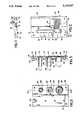
- FIG. 1is a perspective and diagrammatic view of an analysis system in accordance with the invention
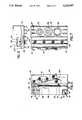
- FIG. 2is a front view of a track plate member of the cuvette assembly employed in the analysis system shown in FIG. 1;
- FIG. 3is a rear view of the track plate shown in FIG. 2;
- FIG. 4is a top view of the track plate shown in FIG. 2;
- FIG. 5is a sectional view taken along the line 5--5 of FIG. 3;
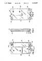
- FIG. 6is a side view of the cuvette assembly employed in the analysis system shown in FIG. 1;
- FIG. 7is a rear view of the cuvette assembly shown in FIG. 6;
- FIG. 8is a top view of the cuvette assembly shown in FIG. 6;
- FIG. 9is a front view of the face plate member of the cuvette assembly shown in FIG. 6;
- FIG. 10is a rear view of the face plate shown in FIG. 9;
- FIG. 11is a sectional view taken along the line 11--11 of FIG. 10;
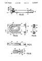
- FIG. 12is a side view of the replaceable cartridge assembly employed in the analysis system shown in FIG. 1;
- FIG. 13is a top plan view of the body member of the cartridge shown in FIG. 12;
- FIG. 14is an end view of the body member shown in FIG. 13;
- FIG. 15is a sectional view taken along the line 15--15 of FIG. 13;
- FIG. 16is a sectional view of a coupling member employed in the cartridge assembly shown in FIG. 12.
- the analysis system shown in FIG. 1is of the type shown in commonly-assigned U.S. Pat. No. 4,997,627, filed Jul. 17, 1987, entitled “Sample Analysis", the disclosure of which is specifically incorporated herein by reference, and includes fluidics module 10 to which sample inlet station 12 is connected by conduit 14, and reservoir 16 for a reagent is connected by conduit 18.
- the sample and reagentare mixed at ambient temperature in module 10 and the resulting mixture is flowed over line 20 through preheater 22 (which raises the mixture temperature to about 29° C.) to inlet 24 of cuvette assembly 30.
- Coupled to cuvette assembly 30are nonactin ionophor ammonium sensing electrode 32, oxygen sensing electrode 34 (FIG. 5) and reference electrode 36 (FIG.
- control unit 40receives temperature signals from cuvette assembly 30 over lines 46 and provides control signals over lines 48 through thermostat 49 to thermoelectric heat pump assembly 50 in cuvette assembly 30.
- Cuvette assembly 30includes face plate 52 (FIGS. 9-11) of transparent acrylic that has a recess 54 (FIGS. 6 and 10) in which transparent urethane gasket 56 is received. Face plate 52 is seated against aluminum track plate member 58 (FIGS. 2-5) and secured by fasteners 60. Inlet 24 is connected to channel 62 that extends to port 64 in the base of cartridge receiving recess 66 that is formed in track plate 58.
- Coupling channel 68extends from port 70 in the base of recess 66 to analysis region 72 for ammonium sensor 32; coupling channel 74 in track plate 58 connects analysis region 72 to analysis region 76 for oxygen sensor 34; serpentine isolation channel 78 connects analysis region 76 to analysis region 80 for reference electrode 36; and isolation loop channel 82 connects analysis region 80 to outlet 84 that in turn is connected to positive displacement piston pump 86.
- Replaceable cartridge 90carries a nylon reaction chamber tube 92 that is about twenty centimeters long and has a capacity of about 115 microliters and is secured in spiral form on aluminum cartridge body 94.
- Urease and glucose oxidase enzymesare co-imobilized on the inner surface of nylon tube 92.
- Tube 92is seated in a groove 170 (FIG. 13) formed in aluminum body 94.
- Resilient coupling elements 96connect the ends of tube 92 to ports 64 and 68 when cartridge 90 is secured in cavity 66 by fastener structure 98 that cooperates with threaded bore 104 in the top wall of track plate 58.
- Post 102 in the base of cavity 66cooperates with recess 196 (FIG. 13) cartridge 90 and provides cartridge alignment.
- Aluminum track plate 58has a width of about six centimeters, a height of about ten centimeters, a thickness of about one centimeter in the vicinity of cartridge recess 66 and a thickness of about six millimeters in the vicinity of analysis regions 72, 76 and 80. Such relative thicknesses can be seen in the view of FIG. 4.
- Boss 103projects from the rear surface of plate 58; recess 101 receives thermistor conductors 46; recess 105 receives temperature sensing thermistor 132, and recesses 106 aligned with analysis regions 72, 76 and 80 receive electrode housing members 108 as indicated in FIGS. 3 and 5.
- Front surface 110 of track plate 58is coated with an inert, nonreactive pinhole free, thermally conductive, dielectric polymer (polyparaxylylene - Parylene) layer of about 0.03 millimeter thickness. Locating pins 112, 114 project from the front surface 110 of plate 58.
- Coated heater groove 62has a width of about 0.8 millimeter, a depth of about 0.9 millimeter with a smoothly radiused base surface, and a length of about eighteen centimeters from inlet port 116 to outlet port 64 in the base surface 118 of recess 66.
- the other grooves 68, 74, 76 and 82 in track plate surface 110are of similar cross sectional configuration, and of shape as indicated in the sectional view of FIG. 5, and are also coated with Parylene.
- track plate 58is secured to heat sink block 120 with fasteners 122.
- the width and height of heat sink block 120are similar to those dimensions of track plate 58, and the body of block 120 is about 0.6 centimeter thick with three centimeter long radiating fins 124 (fins 124 being broken off in FIG. 8) extending therefrom.
- Mounted on the side surface of a fin 124 of heat sink block 120is thermostat 49 and clamped between heat sink block 120 and track plate 58 is an assembly 50 of three 12-watt maximum capacity thermoelectric heat pump units 126 (Material Electronic Product Corporation Part No. CP1.0-63-06L) that are interconnected in series with thermostat 49 between control unit lines 48-1 and 48-2.
- thermoelectric heat pump units 126Material Electronic Product Corporation Part No. CP1.0-63-06L
- the heat pump units 126are sandwiched between and are in thermal contact with heat sink 120 and track plate 58 (their cold faces being thermally coupled to track plate 58 and their hot faces being thermally coupled to heat sink 120); silicone rubber fiberglass reinforced insulator sheet 128 surrounds the heat pump units 126; and similar insulator sheets 130 are provided on the side and end surfaces of the track plate - face plate assembly.
- Thermistor 132is secured in a recess 105 in track plate 58 immediately adjacent oxygen sensing electrode 34.
- Face plate 52is of clear acrylic and is secured to track plate 58 with fasteners 50 that pass through holes 140.
- Inlet line 24is secured in port 142.
- An inclined passage in face plate 52extends to port 144 on the rear surface 146 of face plate 52 that is surrounded by groove 148 that receives a sealing O-ring 150 as indicated in FIG. 6.
- outlet line 84is secured in recess 152 and communicates through inclined passage 154 to port 156 in the rear surface 146 of face plate 52 that is surrounded by O-ring receiving groove 158.
- Recess 160receives track plate locating pin 112; and recess 162 receives locating pin 114.
- recess 56Formed in face plate 52 is recess 56 that is about three millimeters deep and receives clear urethane gasket 54 that has a thickness about 0.1 millimeter greater than the depth of recess 56 such that gasket 54 overlies and is compressed to form a transparent outer boundary of the flow passage defined by the grooves 62, 68, 74, 76 and 82 in track plate 58.
- apertures 164Also carried by face plate 52 in apertures 164 are two spring biased ball plungers 166 (FIG. 8) that provide frictional resistance and positively seat cartridge 90 against the metal wall surface of cartridge recess 66.
- cartridge 90includes aluminum body 94 that has a length of about five centimeters and a width of about 2.5 centimeters. Formed in the upper surface of body 94 is a spiral groove 170 that has an inclined base 172 (as indicated in FIG. 15) and tube retaining lip structure 174 at its upper edge. The ends of reaction chamber tube 92 are inserted into resilient couplings 96 and tube 92 is inserted into groove 170 in spiral configuration and couplings 96 are secured in tab portions 176 at the end of body 94 that are spaced about one centimeter from end surface 178 of the tube receiving groove portion of body 94.
- Each seal coupling 96is of 50 durometer black EP rubber and has a length of about 1.25 centimeters with a body portion 180 of about 0.6 centimeter length and one half centimeter diameter with cylindrical recess 182 that receives an end of reaction chamber tube 92; a reduced diameter connector portion 184 of about 0.4 centimeter length with a through passage 186 of about one millimeter diameter; and a seal portion 188 into which passage 186 extends and terminates in a flared port 190 that has an end diameter of about two millimeters.
- Seal portion 188 of coupling 96is received in slot 192 and seated on surface 194 so its end surface 195 projects beyond end body tab 176 as indicated in FIG. 12.
- Delrin cap 198carries fastener 98 and is secured to aluminum body 94 by bolts 200.
- the reaction chamber cartridge 90is replaceably inserted into the cuvette assembly 30 and secured by fastener 98 with the end surfaces 195 of the seal members 96 seated against and compressed in sealing relation on ports 64 and 70 to complete a series flow circuit between serpentine heater 62 and isolation channel 68. Cartridge 90 permits ready replacement of the reaction chamber 92 as desired.
- track plate 58is maintained at a temperature of 31° ⁇ 0.1° C. by control unit 40 that responds to signals from thermistor 132 and operates the thermoelectric units 126.
- Specified volumes of sample to be analyzed and acidic reagentare transferred into mixing module 10.
- one milliliter volume syringe pump 86is operated to pull the sample reagent mixture from module 10 through preheater 22, Parylene coated serpentine heater channel 62 and reaction chamber coil 92 into the Parylene coated analysis and reference channel regions 72, 76 and 80 of the electrode 32, 34, 36 at a flow rate of about 200 microliters per second. In this condition, a first portion of the sample mixture is at the 31° C.
- the diluted sample portion contacting electrodes 32, 34 and 36contains unconverted sample that has not been acted upon by the enzymes to convert urea to ammonium ions and to convert glucose to hydrogen peroxide.
- Pump 86is then operated in bidirectional mode (alternate forward and backward directions of piston movement) to oscillate the diluted sample portions in the reaction chamber 92 and the analysis regions 72, 76 and 80 back and forth over a distance of about two centimeter.
- This bidirectional flow modepromotes enzyme - sample contact within reaction chamber 92 and equilibration at electrodes 32, 34 and 36.
- the bidirectional mode of operation of pump 86is then terminated and the outputs from electrodes 32, 34, 36 are recorded by control unit 40 to provide first (pre-enzymatic reaction) sample data values.
- pump 86is operated in unidirectional flow mode to pull the second diluted sample portion from reaction chamber 92 into the analysis regions 72, 76 and 80 of electrodes 32, 34 and 36. Pump 86 is again operated in bidirectional flow mode to oscillate the second sample portion in alternate directions to promote electrode equilibration. After that equilibration interval, a second set of data readings are taken, that data including information on the apparent oxygen and ammonium concentrations in the converted sample mixture.
- pump 86is operated in unidirectional flow mode to discard the sample to waste and the flow path is washed with buffer solution.
- the two sets of dataprovide pre-enzymatic reaction (background) measurements representing interferring contribution to electrode response; and post enzymatic reaction measurements.
- Cartridge 90is readily removed from cuvette assembly 30 to change or replace the reaction chamber tube 92 as desired, and readily reinserted into cavity 66 with its upper body surface biased against heat sink 120 by biasing members 166, and reaction chamber tube 92 sealingly connected in the series flow path by resilient couplings 96.
Landscapes
- Health & Medical Sciences (AREA)
- Chemical & Material Sciences (AREA)
- Clinical Laboratory Science (AREA)
- Chemical Kinetics & Catalysis (AREA)
- Analytical Chemistry (AREA)
- General Health & Medical Sciences (AREA)
- Hematology (AREA)
- Automatic Analysis And Handling Materials Therefor (AREA)
- Apparatus Associated With Microorganisms And Enzymes (AREA)
Abstract
Description
Claims (23)
Priority Applications (1)
| Application Number | Priority Date | Filing Date | Title |
|---|---|---|---|
| US07/360,008US5133937A (en) | 1989-06-01 | 1989-06-01 | Analysis system having a removable reaction cartridge and temperature control |
Applications Claiming Priority (1)
| Application Number | Priority Date | Filing Date | Title |
|---|---|---|---|
| US07/360,008US5133937A (en) | 1989-06-01 | 1989-06-01 | Analysis system having a removable reaction cartridge and temperature control |
Publications (1)
| Publication Number | Publication Date |
|---|---|
| US5133937Atrue US5133937A (en) | 1992-07-28 |
Family
ID=23416220
Family Applications (1)
| Application Number | Title | Priority Date | Filing Date |
|---|---|---|---|
| US07/360,008Expired - Fee RelatedUS5133937A (en) | 1989-06-01 | 1989-06-01 | Analysis system having a removable reaction cartridge and temperature control |
Country Status (1)
| Country | Link |
|---|---|
| US (1) | US5133937A (en) |
Cited By (31)
| Publication number | Priority date | Publication date | Assignee | Title |
|---|---|---|---|---|
| US5503985A (en)* | 1993-02-18 | 1996-04-02 | Cathey; Cheryl A. | Disposable device for diagnostic assays |
| US5798215A (en)* | 1993-02-18 | 1998-08-25 | Biocircuits Corporation | Device for use in analyte detection assays |
| US5849208A (en)* | 1995-09-07 | 1998-12-15 | Microfab Technoologies, Inc. | Making apparatus for conducting biochemical analyses |
| US5863506A (en)* | 1996-11-12 | 1999-01-26 | Beckman Instruments, Inc. | Automatic chemistry analyzer with improved heated reaction cup assembly |
| US6004512A (en)* | 1995-12-08 | 1999-12-21 | Mj Research | Sample cartridge slide block |
| WO2000072970A1 (en)* | 1999-05-28 | 2000-12-07 | Cepheid | Cartridge for conducting a chemical reaction |
| US6379910B1 (en)* | 1997-06-05 | 2002-04-30 | Nihon Kohden Corporation | Measuring apparatus and method for material or organism inducing PH-change of substrate solution |
| EP1224976A1 (en)* | 2000-12-28 | 2002-07-24 | F. Hoffmann-La Roche Ag | Method, system and cartridge for processing a nucleic acid sample by oscillating the cartridge |
| US6432721B1 (en)* | 1999-10-29 | 2002-08-13 | Honeywell International Inc. | Meso sniffer: a device and method for active gas sampling using alternating flow |
| US20040106097A1 (en)* | 2002-11-14 | 2004-06-03 | Roche Molecular Systems, Inc. | Method, system and reaction vessel for processing a biological sample contained in a liquid |
| US20040132220A1 (en)* | 2001-01-08 | 2004-07-08 | Leonard Fish | Diagnostic instruments and methods for detecting analytes |
| US6818185B1 (en)* | 1999-05-28 | 2004-11-16 | Cepheid | Cartridge for conducting a chemical reaction |
| JP2007536542A (en)* | 2004-05-06 | 2007-12-13 | シーメンス アクチエンゲゼルシヤフト | Microfluidic system |
| DE102007017681A1 (en)* | 2007-04-14 | 2009-01-08 | Papst Licensing Gmbh & Co. Kg | Device for determining activity of enzymes in liquid test sample containing enzyme and enzyme inhibitor, comprises chromatography column, which contains substrate and substance bound to substrate |
| EP1325110A4 (en)* | 2000-10-02 | 2009-03-25 | Thomas F Cannon | Automated bioculture and bioculture experiments system |
| JP2009525465A (en)* | 2006-01-30 | 2009-07-09 | ビーピー オイル インターナショナル リミテッド | Sample plate for liquid analysis in the essential oil process |
| US20100047774A1 (en)* | 2005-06-23 | 2010-02-25 | Koninklijke Philips Electronics, N.V. | Cartridge, system and method for automated medical diagnostics |
| US20110256617A1 (en)* | 2010-04-15 | 2011-10-20 | Ali S.P.A. - Carpigiani Group | Device for detecting the bacterial charge in a liquid or semi-liquid food product |
| JP2012150130A (en)* | 2006-04-26 | 2012-08-09 | Nikkiso Co Ltd | Biological component measuring apparatus and calibration method of biological component measuring apparatus |
| US20120258545A1 (en)* | 2011-04-06 | 2012-10-11 | Ash Stephen R | Measuring chemical properties of a sample fluid in dialysis systems |
| US8441629B2 (en) | 2009-04-15 | 2013-05-14 | Biocartis Sa | Optical detection system for monitoring rtPCR reaction |
| US8512637B2 (en) | 2009-05-06 | 2013-08-20 | Biocartis Sa | Device for cutting a sample carrier |
| US8641971B2 (en) | 2009-04-14 | 2014-02-04 | Biocartis Sa | HIFU induced cavitation with reduced power threshold |
| JP2015516583A (en)* | 2012-05-15 | 2015-06-11 | ウェルスタット ダイアグノスティクス,エルエルシー | Clinical diagnostic system including instrument and cartridge |
| US9079182B2 (en) | 2009-04-15 | 2015-07-14 | Biocartis Nv | Protection of bioanalytical sample chambers |
| WO2015187849A2 (en) | 2014-06-04 | 2015-12-10 | Lucigen Corporation | Sample collection and analysis devices |
| US9927333B2 (en)* | 2010-05-29 | 2018-03-27 | Gerstel Systemtechnik Gmbh & Co. Kg | Method for preparing a sample for chromatographic separation processes and systems for carrying out a sample preparation |
| US20180209921A1 (en)* | 2017-01-20 | 2018-07-26 | Mallinckrodt Nuclear Medicine Llc | Systems and methods for assaying an eluate of a radionuclide generator |
| KR102104741B1 (en)* | 2019-02-15 | 2020-06-01 | 국민대학교산학협력단 | Sliding type replaceable fluid analysis chamber module |
| US20210299668A1 (en)* | 2020-03-30 | 2021-09-30 | Singular Genomics Systems, Inc. | Sequencing system with preheating |
| US20210340485A1 (en)* | 2017-05-04 | 2021-11-04 | Universität Zürich | Cell culture device |
Citations (16)
| Publication number | Priority date | Publication date | Assignee | Title |
|---|---|---|---|---|
| US3515491A (en)* | 1966-10-27 | 1970-06-02 | Gilford Instr Labor Inc | Fluid sample flow cell |
| US3915804A (en)* | 1974-07-15 | 1975-10-28 | Corning Glass Works | Apparatus and method for measuring conductivity change in a urea-urease reaction |
| US3926734A (en)* | 1973-12-21 | 1975-12-16 | Owens Illinois Inc | Urea analysis |
| US4052161A (en)* | 1974-08-22 | 1977-10-04 | The Perkin-Elmer Corporation | Kinetic analyzer |
| US4066365A (en)* | 1976-05-28 | 1978-01-03 | The Perkin-Elmer Corporation | Temperature control apparatus |
| US4153513A (en)* | 1976-09-20 | 1979-05-08 | Boehringer Mannheim Gmbh | Method and apparatus for the continuous determination of the concentration of an enzyme substrate |
| US4207394A (en)* | 1976-01-28 | 1980-06-10 | Mcdonnell Douglas Corporation | Process and apparatus for analyzing specimens for the presence of microorganisms therein |
| US4367041A (en)* | 1980-08-25 | 1983-01-04 | Micromeritics Instrument Corporation | Chromatograph detection system |
| US4377560A (en)* | 1981-07-13 | 1983-03-22 | Occidental Research Corporation | Process for producing low aluminum content phosphoric acid from high aluminum matrix |
| US4420564A (en)* | 1980-11-21 | 1983-12-13 | Fuji Electric Company, Ltd. | Blood sugar analyzer having fixed enzyme membrane sensor |
| US4443407A (en)* | 1981-04-02 | 1984-04-17 | Instrumentation Laboratory Inc. | Analysis system |
| US4476005A (en)* | 1982-10-04 | 1984-10-09 | Hitachi, Ltd. | Urease-immobilized urea electrode and process for preparing the same |
| US4490235A (en)* | 1981-07-13 | 1984-12-25 | Claudio Calzi | Electrochemical cell provided with selective electrodes and at least one chemical reactor, for indirect measurement of clinical-chemical parameters |
| US4525765A (en)* | 1982-05-05 | 1985-06-25 | Siemens Aktiengesellschaft | Protective circuit for a switching transistor |
| US4640821A (en)* | 1985-07-16 | 1987-02-03 | Fisher Scientific Company | Analysis apparatus |
| US4759828A (en)* | 1987-04-09 | 1988-07-26 | Nova Biomedical Corporation | Glucose electrode and method of determining glucose |
- 1989
- 1989-06-01USUS07/360,008patent/US5133937A/ennot_activeExpired - Fee Related
Patent Citations (16)
| Publication number | Priority date | Publication date | Assignee | Title |
|---|---|---|---|---|
| US3515491A (en)* | 1966-10-27 | 1970-06-02 | Gilford Instr Labor Inc | Fluid sample flow cell |
| US3926734A (en)* | 1973-12-21 | 1975-12-16 | Owens Illinois Inc | Urea analysis |
| US3915804A (en)* | 1974-07-15 | 1975-10-28 | Corning Glass Works | Apparatus and method for measuring conductivity change in a urea-urease reaction |
| US4052161A (en)* | 1974-08-22 | 1977-10-04 | The Perkin-Elmer Corporation | Kinetic analyzer |
| US4207394A (en)* | 1976-01-28 | 1980-06-10 | Mcdonnell Douglas Corporation | Process and apparatus for analyzing specimens for the presence of microorganisms therein |
| US4066365A (en)* | 1976-05-28 | 1978-01-03 | The Perkin-Elmer Corporation | Temperature control apparatus |
| US4153513A (en)* | 1976-09-20 | 1979-05-08 | Boehringer Mannheim Gmbh | Method and apparatus for the continuous determination of the concentration of an enzyme substrate |
| US4367041A (en)* | 1980-08-25 | 1983-01-04 | Micromeritics Instrument Corporation | Chromatograph detection system |
| US4420564A (en)* | 1980-11-21 | 1983-12-13 | Fuji Electric Company, Ltd. | Blood sugar analyzer having fixed enzyme membrane sensor |
| US4443407A (en)* | 1981-04-02 | 1984-04-17 | Instrumentation Laboratory Inc. | Analysis system |
| US4377560A (en)* | 1981-07-13 | 1983-03-22 | Occidental Research Corporation | Process for producing low aluminum content phosphoric acid from high aluminum matrix |
| US4490235A (en)* | 1981-07-13 | 1984-12-25 | Claudio Calzi | Electrochemical cell provided with selective electrodes and at least one chemical reactor, for indirect measurement of clinical-chemical parameters |
| US4525765A (en)* | 1982-05-05 | 1985-06-25 | Siemens Aktiengesellschaft | Protective circuit for a switching transistor |
| US4476005A (en)* | 1982-10-04 | 1984-10-09 | Hitachi, Ltd. | Urease-immobilized urea electrode and process for preparing the same |
| US4640821A (en)* | 1985-07-16 | 1987-02-03 | Fisher Scientific Company | Analysis apparatus |
| US4759828A (en)* | 1987-04-09 | 1988-07-26 | Nova Biomedical Corporation | Glucose electrode and method of determining glucose |
Non-Patent Citations (6)
| Title |
|---|
| Gilford Instrument Laboratories, Inc., Spectrophotometers, "Stasar III", 1975, pp. 1.1-3.6. |
| Gilford Instrument Laboratories, Inc., Spectrophotometers, Stasar III , 1975, pp. 1.1 3.6.* |
| Leon, Luis P. "Continuous-Flow Analysis for Glucose in Serum, with Use of Hexokinase and Glucose-6-Phosphate Dehydrogenase Co-Immobilized in Tubular Form", Clin. Chem. 26/1, 123-129 (1980). |
| Leon, Luis P. Continuous Flow Analysis for Glucose in Serum, with Use of Hexokinase and Glucose 6 Phosphate Dehydrogenase Co Immobilized in Tubular Form , Clin. Chem. 26/1, 123 129 (1980).* |
| Pacakova, Vera "Use of the Clark Oxygen Sensor With Immobilized Enzymes for Determinations in Flow Systems", Analytica Chimica Acta, 159 (1984) pp. 71-79. |
| Pacakova, Vera Use of the Clark Oxygen Sensor With Immobilized Enzymes for Determinations in Flow Systems , Analytica Chimica Acta, 159 (1984) pp. 71 79.* |
Cited By (53)
| Publication number | Priority date | Publication date | Assignee | Title |
|---|---|---|---|---|
| US5798215A (en)* | 1993-02-18 | 1998-08-25 | Biocircuits Corporation | Device for use in analyte detection assays |
| US5503985A (en)* | 1993-02-18 | 1996-04-02 | Cathey; Cheryl A. | Disposable device for diagnostic assays |
| US6334980B1 (en) | 1995-09-07 | 2002-01-01 | Microfab Technologies Inc. | Flexible apparatus with ablation formed chamber(s) for conducting bio-chemical analyses |
| US5849208A (en)* | 1995-09-07 | 1998-12-15 | Microfab Technoologies, Inc. | Making apparatus for conducting biochemical analyses |
| US6004512A (en)* | 1995-12-08 | 1999-12-21 | Mj Research | Sample cartridge slide block |
| US5863506A (en)* | 1996-11-12 | 1999-01-26 | Beckman Instruments, Inc. | Automatic chemistry analyzer with improved heated reaction cup assembly |
| US6379910B1 (en)* | 1997-06-05 | 2002-04-30 | Nihon Kohden Corporation | Measuring apparatus and method for material or organism inducing PH-change of substrate solution |
| WO2000072970A1 (en)* | 1999-05-28 | 2000-12-07 | Cepheid | Cartridge for conducting a chemical reaction |
| US8168442B2 (en) | 1999-05-28 | 2012-05-01 | Cepheid | Cartridge for conducting a chemical reaction |
| US8709363B2 (en) | 1999-05-28 | 2014-04-29 | Cepheid | Cartridge for conducting a chemical reaction |
| JP2003500674A (en)* | 1999-05-28 | 2003-01-07 | シーフィード | Cartridge for controlling chemical reactions |
| US9322052B2 (en) | 1999-05-28 | 2016-04-26 | Cepheid | Cartridge for conducting a chemical reaction |
| US6818185B1 (en)* | 1999-05-28 | 2004-11-16 | Cepheid | Cartridge for conducting a chemical reaction |
| US20050042137A1 (en)* | 1999-05-28 | 2005-02-24 | Cepheid | Cartridge for conducting a chemical reaction |
| AU781122B2 (en)* | 1999-05-28 | 2005-05-05 | Cepheid | Cartridge for conducting a chemical reaction |
| US6432721B1 (en)* | 1999-10-29 | 2002-08-13 | Honeywell International Inc. | Meso sniffer: a device and method for active gas sampling using alternating flow |
| EP1325110A4 (en)* | 2000-10-02 | 2009-03-25 | Thomas F Cannon | Automated bioculture and bioculture experiments system |
| US20050170496A1 (en)* | 2000-12-28 | 2005-08-04 | Roche Molecular Systems, Inc. | Method for processing a nucleic acid sample by oscillating a cartridge, a system and a cartridge for performing such a method |
| US6921639B2 (en) | 2000-12-28 | 2005-07-26 | Roche Molecular Systems, Inc. | Method for processing a nucleic acid sample by oscillating a cartridge, a system and a cartridge for performing such a method |
| US7435575B2 (en) | 2000-12-28 | 2008-10-14 | Roche Molecular Systems, Inc. | Method for processing a nucleic acid sample by oscillating a cartridge, a system and a cartridge for performing such a method |
| US20020155475A1 (en)* | 2000-12-28 | 2002-10-24 | Peter Vischer | Method for processing a nucleic acid sample by oscillating a cartridge, a system and a cartridge for performing such a method |
| EP1224976A1 (en)* | 2000-12-28 | 2002-07-24 | F. Hoffmann-La Roche Ag | Method, system and cartridge for processing a nucleic acid sample by oscillating the cartridge |
| US7435384B2 (en) | 2001-01-08 | 2008-10-14 | Leonard Fish | Diagnostic instrument with movable electrode mounting member and methods for detecting analytes |
| US20040132220A1 (en)* | 2001-01-08 | 2004-07-08 | Leonard Fish | Diagnostic instruments and methods for detecting analytes |
| US20040106097A1 (en)* | 2002-11-14 | 2004-06-03 | Roche Molecular Systems, Inc. | Method, system and reaction vessel for processing a biological sample contained in a liquid |
| JP2007536542A (en)* | 2004-05-06 | 2007-12-13 | シーメンス アクチエンゲゼルシヤフト | Microfluidic system |
| US20100047774A1 (en)* | 2005-06-23 | 2010-02-25 | Koninklijke Philips Electronics, N.V. | Cartridge, system and method for automated medical diagnostics |
| US9568424B2 (en) | 2005-06-23 | 2017-02-14 | Biocartis Nv | Cartridge, system and method for automated medical diagnostics |
| JP2009525465A (en)* | 2006-01-30 | 2009-07-09 | ビーピー オイル インターナショナル リミテッド | Sample plate for liquid analysis in the essential oil process |
| JP2012150130A (en)* | 2006-04-26 | 2012-08-09 | Nikkiso Co Ltd | Biological component measuring apparatus and calibration method of biological component measuring apparatus |
| DE102007017681A1 (en)* | 2007-04-14 | 2009-01-08 | Papst Licensing Gmbh & Co. Kg | Device for determining activity of enzymes in liquid test sample containing enzyme and enzyme inhibitor, comprises chromatography column, which contains substrate and substance bound to substrate |
| US8641971B2 (en) | 2009-04-14 | 2014-02-04 | Biocartis Sa | HIFU induced cavitation with reduced power threshold |
| US9097626B2 (en) | 2009-04-14 | 2015-08-04 | Biocartis Nv | HIFU induced cavitation with reduced power threshold |
| US8986612B2 (en) | 2009-04-14 | 2015-03-24 | Biocartis Nv | HIFU induced cavitation with reduced power threshold |
| US9079182B2 (en) | 2009-04-15 | 2015-07-14 | Biocartis Nv | Protection of bioanalytical sample chambers |
| US8441629B2 (en) | 2009-04-15 | 2013-05-14 | Biocartis Sa | Optical detection system for monitoring rtPCR reaction |
| US8512637B2 (en) | 2009-05-06 | 2013-08-20 | Biocartis Sa | Device for cutting a sample carrier |
| US20110256617A1 (en)* | 2010-04-15 | 2011-10-20 | Ali S.P.A. - Carpigiani Group | Device for detecting the bacterial charge in a liquid or semi-liquid food product |
| US9756870B2 (en)* | 2010-04-15 | 2017-09-12 | Ali S.P.A.-Carpigiani Group | Device for detecting the bacterial charge in a liquid or semi-liquid food product |
| US10801930B2 (en) | 2010-05-29 | 2020-10-13 | Gerstel Systemtechnik Gmbh & Co. Kg | Method for preparing a sample for chromatographic separation processes and system for carrying out a sample preparation |
| US9927333B2 (en)* | 2010-05-29 | 2018-03-27 | Gerstel Systemtechnik Gmbh & Co. Kg | Method for preparing a sample for chromatographic separation processes and systems for carrying out a sample preparation |
| US8945936B2 (en)* | 2011-04-06 | 2015-02-03 | Fresenius Medical Care Holdings, Inc. | Measuring chemical properties of a sample fluid in dialysis systems |
| US20120258545A1 (en)* | 2011-04-06 | 2012-10-11 | Ash Stephen R | Measuring chemical properties of a sample fluid in dialysis systems |
| US9599599B2 (en) | 2011-04-06 | 2017-03-21 | Fresenius Medical Care Holdings, Inc. | Measuring chemical properties of a sample fluid in dialysis systems |
| JP2015516583A (en)* | 2012-05-15 | 2015-06-11 | ウェルスタット ダイアグノスティクス,エルエルシー | Clinical diagnostic system including instrument and cartridge |
| WO2015187849A2 (en) | 2014-06-04 | 2015-12-10 | Lucigen Corporation | Sample collection and analysis devices |
| US10093918B2 (en) | 2014-06-04 | 2018-10-09 | Lucigen Corporation | Sample collection and analysis devices |
| US20180209921A1 (en)* | 2017-01-20 | 2018-07-26 | Mallinckrodt Nuclear Medicine Llc | Systems and methods for assaying an eluate of a radionuclide generator |
| US20210340485A1 (en)* | 2017-05-04 | 2021-11-04 | Universität Zürich | Cell culture device |
| US12195717B2 (en)* | 2017-05-04 | 2025-01-14 | Universität Zürich | Cell culture device |
| KR102104741B1 (en)* | 2019-02-15 | 2020-06-01 | 국민대학교산학협력단 | Sliding type replaceable fluid analysis chamber module |
| US11130126B2 (en)* | 2019-02-15 | 2021-09-28 | Kookmin University Industry Academy Cooperation Foundation | Sliding type replaceable fluid analysis chamber module |
| US20210299668A1 (en)* | 2020-03-30 | 2021-09-30 | Singular Genomics Systems, Inc. | Sequencing system with preheating |
Similar Documents
| Publication | Publication Date | Title |
|---|---|---|
| US5133937A (en) | Analysis system having a removable reaction cartridge and temperature control | |
| US4654127A (en) | Self-calibrating single-use sensing device for clinical chemistry and method of use | |
| CA1316981C (en) | Sample analysis | |
| US4443407A (en) | Analysis system | |
| US12208393B2 (en) | Thermal control system for controlling the temperature of a fluid | |
| US4361539A (en) | Analysis system | |
| US6814846B1 (en) | Device to operate a laboratory microchip | |
| EP1481246B1 (en) | Apparatus and methods for analyte measurement and immunoassay | |
| CA2439924C (en) | Analysis device | |
| EP0179129B1 (en) | Self-calibrating single-use sensing device for clinical chemistry analyzer | |
| US6919045B1 (en) | Supply element for a laboratory microchip | |
| US9423393B2 (en) | Analytical test cartridge; and, methods | |
| WO1999046591A3 (en) | Integrated assay device and methods of production and use | |
| US20090041623A1 (en) | Fluid analyzing apparatus | |
| RU2658516C2 (en) | Apparatus with electrochemical sensor matrix | |
| CN111344062B (en) | Sensor cartridge | |
| EP0299658A2 (en) | Analysis system | |
| CN111495451A (en) | Biochemical index detection integrated chip and detection method and application thereof | |
| US5037737A (en) | Analysis by sensor placement in recprocating flow | |
| CN102548659A (en) | Flat body in the manner of a chip card for biochemical analysis and method for the use thereof | |
| EP0805350B1 (en) | An apparatus and method for the determination of substances in solution, suspension or emulsion by differential pH measurement | |
| CN217688681U (en) | Sample analyzer | |
| US9493812B2 (en) | Method for detecting a target analyte that exhibits protease enzyme activity | |
| CN105628660A (en) | Passive microvalve POCT chip | |
| JPH0213741B2 (en) |
Legal Events
| Date | Code | Title | Description |
|---|---|---|---|
| AS | Assignment | Owner name:FISHER SCIENTIFIC COMPANY, PITTSBURGH, PA A CORP. Free format text:ASSIGNMENT OF ASSIGNORS INTEREST.;ASSIGNORS:FRACKLETON, JOHN J.;RASMUSSEN, JAMES E.;MILESKY, LAWRENCE;REEL/FRAME:005112/0543 Effective date:19890627 | |
| AS | Assignment | Owner name:INIZIATIVE MARITTIME 1991, S.R.L. A CORPORATION Free format text:ASSIGNMENT OF ASSIGNORS INTEREST.;ASSIGNOR:FISHER SCIENTIFIC COMPANY, A CORPORATION OF DE;REEL/FRAME:005881/0919 Effective date:19911023 | |
| AS | Assignment | Owner name:CITIBANK N.A. Free format text:SECURITY INTEREST;ASSIGNOR:INIZIATIVE MARITTIME 1991, S.R.L.;REEL/FRAME:005913/0325 Effective date:19911023 | |
| AS | Assignment | Owner name:IL HOLDING S.P.A. Free format text:CHANGE OF NAME;ASSIGNOR:INIZIATIVE MARITTIME 1991 S.R.L.);REEL/FRAME:006179/0978 Effective date:19920219 | |
| REMI | Maintenance fee reminder mailed | ||
| LAPS | Lapse for failure to pay maintenance fees | ||
| FP | Lapsed due to failure to pay maintenance fee | Effective date:19960731 | |
| STCH | Information on status: patent discontinuation | Free format text:PATENT EXPIRED DUE TO NONPAYMENT OF MAINTENANCE FEES UNDER 37 CFR 1.362 |