US5133729A - Motor driven hand piece for a surgical tool - Google Patents
Motor driven hand piece for a surgical toolDownload PDFInfo
- Publication number
- US5133729A US5133729AUS07/569,082US56908290AUS5133729AUS 5133729 AUS5133729 AUS 5133729AUS 56908290 AUS56908290 AUS 56908290AUS 5133729 AUS5133729 AUS 5133729A
- Authority
- US
- United States
- Prior art keywords
- drive shaft
- seal element
- surgical device
- dynamic seal
- surgical tool
- Prior art date
- Legal status (The legal status is an assumption and is not a legal conclusion. Google has not performed a legal analysis and makes no representation as to the accuracy of the status listed.)
- Expired - Lifetime
Links
Images


Classifications
- A—HUMAN NECESSITIES
- A61—MEDICAL OR VETERINARY SCIENCE; HYGIENE
- A61B—DIAGNOSIS; SURGERY; IDENTIFICATION
- A61B17/00—Surgical instruments, devices or methods
- A61B17/32—Surgical cutting instruments
- A61B17/320016—Endoscopic cutting instruments, e.g. arthroscopes, resectoscopes
- A61B17/32002—Endoscopic cutting instruments, e.g. arthroscopes, resectoscopes with continuously rotating, oscillating or reciprocating cutting instruments
- Y—GENERAL TAGGING OF NEW TECHNOLOGICAL DEVELOPMENTS; GENERAL TAGGING OF CROSS-SECTIONAL TECHNOLOGIES SPANNING OVER SEVERAL SECTIONS OF THE IPC; TECHNICAL SUBJECTS COVERED BY FORMER USPC CROSS-REFERENCE ART COLLECTIONS [XRACs] AND DIGESTS
- Y10—TECHNICAL SUBJECTS COVERED BY FORMER USPC
- Y10T—TECHNICAL SUBJECTS COVERED BY FORMER US CLASSIFICATION
- Y10T408/00—Cutting by use of rotating axially moving tool
- Y10T408/65—Means to drive tool
Definitions
- the inventionrelates to surgical devices having motor driven handpieces which receive rotatable surgical tools.
- Surgical devicestypically include a handpiece containing a motor and having a distal portion adapted to receive a surgical tool, e.g., an arthroplasty resector.
- a surgical toole.g., an arthroplasty resector.
- the distal tip of the surgical toolusually defines a vacuum passage through which fluid and tissue are removed from a patient's body during surgery.
- the passageextends from the distal tip of the surgical tool through the tool and into a drain tube in the handpiece which is connected to a suction device.
- the fluid and tissuealso enter the motor through the space created between the motor housing and the rotating drive shaft, causing the motor to malfunction and corrode.
- One known solution to this problemis to provide flexible lip seals or O-rings around the drive shaft which contact the surface of the drive shaft and seal it parallel to its axis of rotation.
- the O-rings and the lips of the lip sealsi.e., those portions of the seals which contact the drive shaft, are very flexible, e.g., formed of silicone rubber, or formed of a cover material and some type of filler such as Teflon® and a graphite compound.
- systems which use the O-ring and lip sealing techniquesare also known to use close tolerance fitting of the bearings with the drive shaft to prevent the surgical device from rotating off center and pulling away from a portion of the seal, thereby allowing fluids to enter the motor housing.
- the inventionfeatures a handpiece adapted to receive a surgical tool, a motor driven drive shaft for rotating the tool about an axis, a static seal element sealed to the motor assembly, and a dynamic seal element sealed to the drive shaft, the seal elements having mating sealing portions defining a face seal in a surface transverse to the axis of rotation of the drive shaft.
- the face sealis in a planar surface perpendicular to the axis of rotation.
- the dynamic seal elementis biased against the static seal element by circumferentially spaced springs that act through an axially movable drive ring and a resilient buffer ring.
- the drive ringSurrounding the drive shaft, the drive ring is rotatably keyed to the shaft and the dynamic seal element.
- An O-ringsurrounds the drive shaft, provides a seal between the shaft and the dynamic seal element, and maintains a distance between the shaft and the dynamic seal element.
- the static seal elementis sealed to the handpiece housing by a pair of silicone O-rings, to prevent fluid from flowing past the motor assembly.
- the dynamic seal element and the static sealare flat lapped within three helium light bands.
- the advantages of the present inventioninclude preventing fluid from entering the motor by providing the face seal transverse to the axis of rotation, particularly in situations where a fluid passageway from the surgical tool exposes the motor housing to fluid.
- the face sealis maintained regardless of whether the drive shaft wobbles, and motor vibrations in the handpiece are reduced.
- the seals between the dynamic seal element and the drive shaft, and between the static seal element and the handpiece housing,further protect the motor.
- FIG. 1is a plan view, partially cut away and in cross section, of a surgical device according to the present invention.
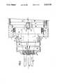
- FIG. 2is an enlarged plan view, partially cut away and in cross section, of a portion of the handpiece shown in FIG. 1, including the drive shaft and the motor housing.
- FIG. 3is a plan view of the portion of the handpiece shown in FIG. 2, but rotated approximately 90° and further cut away and in cross section to show additional detail.
- FIG. 4is a perspective view of a rotatable surgical tool used with the surgical device shown in FIG. 1 and connectable to the drive shaft shown in FIGS. 2 and 3.
- FIG. 4ais an enlarged perspective view, partially cut away and in cross section, of the detail area of FIG. 4.
- a surgical deviceincludes a cylindrical surgical handpiece 10, having an outer housing 11, the length and diameter of which are sized and textured to fit comfortably into the palm of a surgeon.
- the distal end of the handpiece 10is adapted to receive a rotatable surgical tool 12 (shown in dotted lines in FIG. 1), e.g., an arthroplasty resector (shown in FIG. 4).
- the tool 12engages a rotatable drive shaft 14 (shown in dotted lines in FIG. 1) which is bonded, e.g.
- Loctite 620 adhesiveto a rotatable motor shaft 16 extending distally from a conventional electric motor 18 (the motor shaft and the motor also shown in dotted lines in FIG. 1) into a recess in the drive shaft 14. This bonding causes the drive shaft 14 to rotate with the motor shaft 16 relative to the handpiece 10, in turn rotating the tool 12.
- a power line 20connects the motor 18 to a power source 22 or other control device to regulate the action of the tool 12, e.g., its rotation speed.
- the distal end of the tool 12defines an opening 13 which communicates with proximal portions of the tool.
- a flange 15shown in detail in FIG. 4a
- fluidcan flow from a patient's body through the tool and collect in a passageway 24 exposed to the drive shaft and motor housing.
- the passageway 24is defined by the open areas between the tool 12 and the inner wall of the handpiece 10, and between the drive shaft 14 and the inner wall of the handpiece. Most of the fluid exits the passageway 24 through a port 26 and a rotary valve 28 into a channel 30 connected to a drain tube 32. Fluid in the channel 30 is then suctioned through the drain tube 32 by a suction source 34 connected to the tube. Nevertheless, it is possible for some fluid to remain within the passageway 24, which presents a potential hazard should the fluid seep into the motor 18 and cause it to malfunction or corrode. As described below in connection with FIGS. 2 and 3, the present invention provides an improved sealing assembly to prevent fluid from reaching the motor 18.
- the handpiece 10further contains a motor housing 36 which includes a ring gear section 38, a ball bearing section 40, and a shoulder section 42, which are pressed and swaged together to form a 3-piece assembly.
- a seal assembly 44Adjacent to the distal end of the motor housing 36 and surrounding the proximal end of the drive shaft 14 is a seal assembly 44 which includes a static seal ring 46 and a dynamic seal ring 48.
- the static ring 46is rotationally fixed relative to the motor housing 36 by a pin 50 that extends from within the motor housing and fits into a slot 52 cut into the proximal face of the static ring.
- the static ring 46is not otherwise attached to the motor housing 36, but rather is held in place against the motor housing by the adjacent dynamic ring 48 which rotates with the drive shaft 14.
- a pair of silicone O-rings 53seal between the static ring 46 and the main housing 11 of the handpiece, to prevent fluid from flowing past the motor assembly.
- a cap ring 54is screwed over a threaded portion of the distal U-shaped end of the drive shaft 14, thereby causing the cap ring to rotate with the drive shaft.
- Adjacent to the cap ring 54is a spring ring 56 captured between the cap ring 54 and shoulder 55 of shaft 14 so as to rotate with the shaft.
- a drive ring 58is rotatably connected to the spring ring 56 by a tab 60 on the drive ring which fits into a slot 62 cut into the spring ring.
- the dynamic ring 48is rotatably connected to the drive ring 58 by a pair of tabs 64 (180° apart), which fit into slots 65 in the dynamic ring.
- a number of springs 66are circumferentially spaced around the drive shaft 14 in holes drilled through the spring ring 56.
- the springs 66act against the cap ring 56 and press the drive ring 58, which is axially movable along the drive shaft 14, toward the dynamic ring 48.
- a buffer ring 68Disposed around the drive shaft 14, between the drive ring 58 and the dynamic ring 48, is a buffer ring 68, which is preferably formed of silicone rubber.
- the buffer ring 68acts as a resilient interface between the drive ring and the dynamic ring to insulate seal rings 46 and 48 from vibrations during operation of the device, and to avoid direct contact between the metal drive ring 58 and the distal surface of the dynamic ring 48, all to increase the operating life of the seal.
- the dynamic ring 48 surrounding the drive shaft 14is sealed thereto by an O-ring 70 disposed in a groove 71 formed in the drive shaft, thus closing a secondary fluid leakage path to the motor and maintaining a constant distance between the drive shaft 14 and the dynamic ring 48 should the drive shaft 14 begin to wobble, thereby helping to preserve the seal formed between the mating portions of the dynamic ring 48 and the static ring 46.
- a tapered proximal end portion 14a of the drive shaft 14is disposed adjacent to the O-ring.
- the tapered portion 14ais bonded as described above to the distal end of the motor shaft 16 (shown in dotted lines), thereby causing the drive shaft 14, and all components described above as being rotatably connected thereto, to rotate with the motor shaft 16 relative to the handpiece 10.
- a washer 72surrounding the motor shaft 16, is a washer 72 which acts as a spacer between the tapered portion 14a and the motor housing 36.
- the mating portions of the static ring 46 and the dynamic ring 48form a face seal 76 in a plane perpendicular to the drive shaft axis 80.
- the face seal 76is formed toward the inner edge of the static ring 46 because the proximal portion of the dynamic ring 48, i.e., that portion which makes contact with the static ring 46, is stepped inwardly on the surface of its outer diameter so that the mating portion of the dynamic ring is approximately 1/3 the width of the mating portion of the static ring 46.
- the face seal 76generally remains at the inner edge of the static ring 46, it can sometimes shift towards an outer edge of the static ring because of a lack of rigidity or a side to side wobble in the drive shaft 14.
- the shape of the dynamic ring 48 and its positioning relative to the static ring 46allow the drive shaft 14 to wobble relative to the motor housing 36 without disturbing the face seal 76, i.e., the mating portion of the dynamic ring simply slides radially along the mating portion of the static ring.
- the dynamic and static rings 48 and 46are preferably formed of silicon carbide and a carbon graphite composite, respectively. Also, in order to provide as effective a face seal as possible, the contacting faces of the dynamic and static rings 48 and 46 are polished to a very flat surface free of scratches and grooves, e.g., flat lapped within two or three helium light bands.
- the solid materials chosenare preferred over the more flexible materials used in previous sealing arrangements, e.g., Teflon and silicone rubber, because they are not sensitive to the material or finish of the drive shaft. Previously used materials were prone to wear out quickly, in part because they contacted the drive shaft itself, a disadvantage that the placement of the rings in the present invention avoids. Finally, the harder materials used in the present invention are resistant to abrasives and other contaminants in the environment, thus ensuring a greater lifetime of use for the motor 18.
- the surgical device of the present inventionprovides several advantages over previously known surgical devices using O-ring or lip seal arrangements. Most notably, an effective face seal is achieved transverse of the axis of rotation of the drive shaft, and the seal is maintained regardless of whether the drive shaft wobbles. In addition, the materials of the sealing elements are not prone to warp or wear out quickly, nor are they likely to become contaminated. And finally, vibrations in the handpiece are reduced.
Landscapes
- Health & Medical Sciences (AREA)
- Surgery (AREA)
- Life Sciences & Earth Sciences (AREA)
- Medical Informatics (AREA)
- Animal Behavior & Ethology (AREA)
- Engineering & Computer Science (AREA)
- Biomedical Technology (AREA)
- Heart & Thoracic Surgery (AREA)
- Orthopedic Medicine & Surgery (AREA)
- Molecular Biology (AREA)
- Nuclear Medicine, Radiotherapy & Molecular Imaging (AREA)
- General Health & Medical Sciences (AREA)
- Public Health (AREA)
- Veterinary Medicine (AREA)
- Surgical Instruments (AREA)
- Saccharide Compounds (AREA)
- Manipulator (AREA)
Abstract
Description
Claims (19)
Priority Applications (9)
| Application Number | Priority Date | Filing Date | Title |
|---|---|---|---|
| US07/569,082US5133729A (en) | 1990-08-17 | 1990-08-17 | Motor driven hand piece for a surgical tool |
| DE69113722TDE69113722T2 (en) | 1990-08-17 | 1991-08-12 | Surgical device. |
| AT91307399TATE128845T1 (en) | 1990-08-17 | 1991-08-12 | SURGICAL DEVICE. |
| DK91307399.5TDK0471533T3 (en) | 1990-08-17 | 1991-08-12 | Surgical device |
| EP91307399AEP0471533B1 (en) | 1990-08-17 | 1991-08-12 | Surgical device |
| ES91307399TES2081438T3 (en) | 1990-08-17 | 1991-08-12 | SURGICAL DEVICE. |
| JP20437991AJP3164607B2 (en) | 1990-08-17 | 1991-08-14 | Surgical equipment |
| CA002049233ACA2049233C (en) | 1990-08-17 | 1991-08-15 | Surgical device |
| AU82529/91AAU637753B2 (en) | 1990-08-17 | 1991-08-16 | Surgical device |
Applications Claiming Priority (1)
| Application Number | Priority Date | Filing Date | Title |
|---|---|---|---|
| US07/569,082US5133729A (en) | 1990-08-17 | 1990-08-17 | Motor driven hand piece for a surgical tool |
Publications (1)
| Publication Number | Publication Date |
|---|---|
| US5133729Atrue US5133729A (en) | 1992-07-28 |
Family
ID=24274034
Family Applications (1)
| Application Number | Title | Priority Date | Filing Date |
|---|---|---|---|
| US07/569,082Expired - LifetimeUS5133729A (en) | 1990-08-17 | 1990-08-17 | Motor driven hand piece for a surgical tool |
Country Status (9)
| Country | Link |
|---|---|
| US (1) | US5133729A (en) |
| EP (1) | EP0471533B1 (en) |
| JP (1) | JP3164607B2 (en) |
| AT (1) | ATE128845T1 (en) |
| AU (1) | AU637753B2 (en) |
| CA (1) | CA2049233C (en) |
| DE (1) | DE69113722T2 (en) |
| DK (1) | DK0471533T3 (en) |
| ES (1) | ES2081438T3 (en) |
Cited By (42)
| Publication number | Priority date | Publication date | Assignee | Title |
|---|---|---|---|---|
| US5437678A (en)* | 1992-11-30 | 1995-08-01 | Neomedix Corporation | Ophthalmic lens removal method and apparatus |
| US5474566A (en)* | 1994-05-05 | 1995-12-12 | United States Surgical Corporation | Self-contained powered surgical apparatus |
| DE4422426A1 (en)* | 1994-06-28 | 1996-01-18 | Kurt Eberle Kg | Surgical instrument for tissue and cartilage removal |
| US5490860A (en)* | 1993-12-08 | 1996-02-13 | Sofamor Danek Properties, Inc. | Portable power cutting tool |
| US5492527A (en)* | 1994-09-09 | 1996-02-20 | Linvatec Corporation | Arthroscopic shaver with rotatable collet and slide aspiration control valve |
| WO1997016123A1 (en) | 1995-10-31 | 1997-05-09 | Smith & Nephew, Inc. | Magnetic switching element for controlling a surgical device |
| WO1997016124A1 (en) | 1995-10-31 | 1997-05-09 | Smith & Nephew, Inc. | Surgical instrument handpiece and system |
| US5628446A (en)* | 1994-05-05 | 1997-05-13 | United States Surgical Corporation | Self-contained powered surgical apparatus |
| US5653374A (en)* | 1994-08-05 | 1997-08-05 | United States Surgical Corporation | Self-contained powered surgical apparatus |
| US5680981A (en)* | 1994-05-05 | 1997-10-28 | United States Surgical Corporation | Self-contained powered surgical apparatus |
| US5779130A (en)* | 1994-08-05 | 1998-07-14 | United States Surgical Corporation | Self-contained powered surgical apparatus |
| US5792167A (en)* | 1996-09-13 | 1998-08-11 | Stryker Corporation | Surgical irrigation pump and tool system |
| US5976165A (en)* | 1997-12-10 | 1999-11-02 | Scimed Life Systems, Inc. | Rotational ablation device having replaceable screw-on burrs |
| US6264087B1 (en) | 1999-07-12 | 2001-07-24 | Powermed, Inc. | Expanding parallel jaw device for use with an electromechanical driver device |
| US6342061B1 (en) | 1996-09-13 | 2002-01-29 | Barry J. Kauker | Surgical tool with integrated channel for irrigation |
| US6348061B1 (en) | 2000-02-22 | 2002-02-19 | Powermed, Inc. | Vessel and lumen expander attachment for use with an electromechanical driver device |
| US6443973B1 (en) | 1999-06-02 | 2002-09-03 | Power Medical Interventions, Inc. | Electromechanical driver device for use with anastomosing, stapling, and resecting instruments |
| US6478681B1 (en) | 2000-11-27 | 2002-11-12 | Duke University | Magnetic couplings for imparting simultaneous rotary and longitudinal oscillations |
| US6488197B1 (en) | 2000-02-22 | 2002-12-03 | Power Medical Interventions, Inc. | Fluid delivery device for use with anastomosing resecting and stapling instruments |
| US6491201B1 (en) | 2000-02-22 | 2002-12-10 | Power Medical Interventions, Inc. | Fluid delivery mechanism for use with anastomosing, stapling, and resecting instruments |
| US6506176B1 (en) | 1999-02-17 | 2003-01-14 | Bausch & Lomb Incorporated | Methods, apparatus and system for removal of lenses from mammalian eyes |
| US6517565B1 (en) | 1999-06-02 | 2003-02-11 | Power Medical Interventions, Inc. | Carriage assembly for controlling a steering wire steering mechanism within a flexible shaft |
| US6517560B1 (en) | 2000-11-27 | 2003-02-11 | Duke University | Hand-held surgical instruments employing magnetic couplings for simultaneous rotary and longitudinal oscillations of distal workpieces |
| US6533157B1 (en) | 2000-02-22 | 2003-03-18 | Power Medical Interventions, Inc. | Tissue stapling attachment for use with an electromechanical driver device |
| US6716233B1 (en) | 1999-06-02 | 2004-04-06 | Power Medical Interventions, Inc. | Electromechanical driver and remote surgical instrument attachment having computer assisted control capabilities |
| US6793652B1 (en) | 1999-06-02 | 2004-09-21 | Power Medical Interventions, Inc. | Electro-mechanical surgical device |
| US6843403B2 (en) | 1999-06-02 | 2005-01-18 | Power Medical Interventions, Inc. | Surgical clamping, cutting and stapling device |
| US20050240206A1 (en)* | 2004-04-21 | 2005-10-27 | Sjostrom Douglas D | Surgical instrument aspiration valve |
| US20050268427A1 (en)* | 2004-05-26 | 2005-12-08 | Rory Britz | Dust extracting device |
| US6981941B2 (en) | 1999-06-02 | 2006-01-03 | Power Medical Interventions | Electro-mechanical surgical device |
| US7032798B2 (en) | 1999-06-02 | 2006-04-25 | Power Medical Interventions, Inc. | Electro-mechanical surgical device |
| US7150747B1 (en) | 2003-01-22 | 2006-12-19 | Smith & Nephew, Inc. | Electrosurgical cutter |
| US20100076477A1 (en)* | 2008-09-22 | 2010-03-25 | Smith & Nephew, Inc. | Drive Shaft For A Surgical Tool |
| US20100102517A1 (en)* | 2008-10-29 | 2010-04-29 | Ajay Kumar | Sealing system for medical/dental handpieces |
| US7918230B2 (en) | 2007-09-21 | 2011-04-05 | Tyco Healthcare Group Lp | Surgical device having a rotatable jaw portion |
| US7951071B2 (en) | 1999-06-02 | 2011-05-31 | Tyco Healthcare Group Lp | Moisture-detecting shaft for use with an electro-mechanical surgical device |
| US7963433B2 (en) | 2007-09-21 | 2011-06-21 | Tyco Healthcare Group Lp | Surgical device having multiple drivers |
| US20110282374A1 (en)* | 2009-02-04 | 2011-11-17 | Sandeep Ambardekar | Disposable and reusable morcellator |
| US20120234325A1 (en)* | 2011-03-17 | 2012-09-20 | Wai To Li | Air Control Valve |
| WO2013173114A2 (en) | 2012-05-16 | 2013-11-21 | Smith & Nephew, Inc. | Reusable blade hub assembly |
| US10617431B2 (en) | 2012-06-26 | 2020-04-14 | DePuy Synthes Products, Inc. | Systems and apparatus for providing motor protection in a power tool and method of manufacturing the same |
| US11309764B2 (en) | 2012-06-26 | 2022-04-19 | DePuy Synthes Products, Inc. | Systems and apparatus for providing motor protection in a power tool and method of manufacturing the same |
Families Citing this family (3)
| Publication number | Priority date | Publication date | Assignee | Title |
|---|---|---|---|---|
| DE69734845T2 (en)* | 1996-09-24 | 2006-09-14 | Xomed Surgical Products, Inc., North Jacksonville | Assembly of surgical blades |
| DE19859217B4 (en)* | 1998-12-21 | 2004-01-29 | Richard Wolf Gmbh | Electromotive drive for a surgical tool |
| US9216062B2 (en)* | 2011-02-15 | 2015-12-22 | Intuitive Surgical Operations, Inc. | Seals and sealing methods for a surgical instrument having an articulated end effector actuated by a drive shaft |
Citations (13)
| Publication number | Priority date | Publication date | Assignee | Title |
|---|---|---|---|---|
| US3409213A (en)* | 1967-01-23 | 1968-11-05 | 500 Inc | Rotary seal and centrifuge incorporation |
| US3519201A (en)* | 1968-05-07 | 1970-07-07 | Us Health Education & Welfare | Seal means for blood separator and the like |
| US3990453A (en)* | 1973-04-25 | 1976-11-09 | Douvas Nicholas G | Apparatus for cataract surgery |
| US4167944A (en)* | 1977-06-27 | 1979-09-18 | Surgical Design Corp. | Rotatable surgical cutting instrument with improved cutter blade wear |
| US4167943A (en)* | 1977-06-27 | 1979-09-18 | Surgical Design Corp. | Blade type rotatable surgical cutting instrument with improved cutter blade wear |
| US4203444A (en)* | 1977-11-07 | 1980-05-20 | Dyonics, Inc. | Surgical instrument suitable for closed surgery such as of the knee |
| US4246902A (en)* | 1978-03-10 | 1981-01-27 | Miguel Martinez | Surgical cutting instrument |
| US4517977A (en)* | 1981-07-24 | 1985-05-21 | Unisearch Limited | Co-axial tube surgical infusion/suction cutter tip |
| EP0189807A2 (en)* | 1985-01-23 | 1986-08-06 | SMITH & NEPHEW DYONICS, INC. | Surgical system for powered instruments |
| EP0190000A2 (en)* | 1985-01-23 | 1986-08-06 | BAXTER INTERNATIONAL INC. (a Delaware corporation) | Surgical instrument |
| US4623028A (en)* | 1985-09-16 | 1986-11-18 | Reed Tool Company | Seal assembly for drill bits |
| US4895146A (en)* | 1982-01-25 | 1990-01-23 | Klaus Draenert | Surgical bone-grinding instrument |
| US4951690A (en)* | 1984-01-31 | 1990-08-28 | Baker John W | Method of drilling through a bone structure |
- 1990
- 1990-08-17USUS07/569,082patent/US5133729A/ennot_activeExpired - Lifetime
- 1991
- 1991-08-12DKDK91307399.5Tpatent/DK0471533T3/enactive
- 1991-08-12ESES91307399Tpatent/ES2081438T3/ennot_activeExpired - Lifetime
- 1991-08-12EPEP91307399Apatent/EP0471533B1/ennot_activeRevoked
- 1991-08-12ATAT91307399Tpatent/ATE128845T1/ennot_activeIP Right Cessation
- 1991-08-12DEDE69113722Tpatent/DE69113722T2/ennot_activeRevoked
- 1991-08-14JPJP20437991Apatent/JP3164607B2/ennot_activeExpired - Lifetime
- 1991-08-15CACA002049233Apatent/CA2049233C/ennot_activeExpired - Fee Related
- 1991-08-16AUAU82529/91Apatent/AU637753B2/ennot_activeExpired
Patent Citations (16)
| Publication number | Priority date | Publication date | Assignee | Title |
|---|---|---|---|---|
| US3409213A (en)* | 1967-01-23 | 1968-11-05 | 500 Inc | Rotary seal and centrifuge incorporation |
| US3519201A (en)* | 1968-05-07 | 1970-07-07 | Us Health Education & Welfare | Seal means for blood separator and the like |
| US3990453A (en)* | 1973-04-25 | 1976-11-09 | Douvas Nicholas G | Apparatus for cataract surgery |
| US4167944A (en)* | 1977-06-27 | 1979-09-18 | Surgical Design Corp. | Rotatable surgical cutting instrument with improved cutter blade wear |
| US4167943A (en)* | 1977-06-27 | 1979-09-18 | Surgical Design Corp. | Blade type rotatable surgical cutting instrument with improved cutter blade wear |
| US4203444B1 (en)* | 1977-11-07 | 1987-07-21 | ||
| US4203444A (en)* | 1977-11-07 | 1980-05-20 | Dyonics, Inc. | Surgical instrument suitable for closed surgery such as of the knee |
| US4246902A (en)* | 1978-03-10 | 1981-01-27 | Miguel Martinez | Surgical cutting instrument |
| US4517977A (en)* | 1981-07-24 | 1985-05-21 | Unisearch Limited | Co-axial tube surgical infusion/suction cutter tip |
| US4895146A (en)* | 1982-01-25 | 1990-01-23 | Klaus Draenert | Surgical bone-grinding instrument |
| US4951690A (en)* | 1984-01-31 | 1990-08-28 | Baker John W | Method of drilling through a bone structure |
| EP0189807A2 (en)* | 1985-01-23 | 1986-08-06 | SMITH & NEPHEW DYONICS, INC. | Surgical system for powered instruments |
| EP0190000A2 (en)* | 1985-01-23 | 1986-08-06 | BAXTER INTERNATIONAL INC. (a Delaware corporation) | Surgical instrument |
| US4649919A (en)* | 1985-01-23 | 1987-03-17 | Precision Surgical Instruments, Inc. | Surgical instrument |
| US4705038A (en)* | 1985-01-23 | 1987-11-10 | Dyonics, Inc. | Surgical system for powered instruments |
| US4623028A (en)* | 1985-09-16 | 1986-11-18 | Reed Tool Company | Seal assembly for drill bits |
Cited By (105)
| Publication number | Priority date | Publication date | Assignee | Title |
|---|---|---|---|---|
| US5437678A (en)* | 1992-11-30 | 1995-08-01 | Neomedix Corporation | Ophthalmic lens removal method and apparatus |
| US5871492A (en)* | 1992-11-30 | 1999-02-16 | Optex Ophthalmologics, Inc. | Rotary device for removing ophthalmic lens |
| US5690641A (en)* | 1992-11-30 | 1997-11-25 | Optex Ophthalmologics, Inc. | Rotary device for removing ophthalmic lens |
| US5490860A (en)* | 1993-12-08 | 1996-02-13 | Sofamor Danek Properties, Inc. | Portable power cutting tool |
| US5628446A (en)* | 1994-05-05 | 1997-05-13 | United States Surgical Corporation | Self-contained powered surgical apparatus |
| US5680981A (en)* | 1994-05-05 | 1997-10-28 | United States Surgical Corporation | Self-contained powered surgical apparatus |
| US5474566A (en)* | 1994-05-05 | 1995-12-12 | United States Surgical Corporation | Self-contained powered surgical apparatus |
| DE4422426A1 (en)* | 1994-06-28 | 1996-01-18 | Kurt Eberle Kg | Surgical instrument for tissue and cartilage removal |
| DE4422426C2 (en)* | 1994-06-28 | 1998-02-26 | Kurt Eberle Kg | Surgical instrument for removing tissue or cartilage |
| US5779130A (en)* | 1994-08-05 | 1998-07-14 | United States Surgical Corporation | Self-contained powered surgical apparatus |
| US5954259A (en)* | 1994-08-05 | 1999-09-21 | United States Surgical Corporation | Self-contained powered surgical apparatus for applying surgical fasteners |
| US5653374A (en)* | 1994-08-05 | 1997-08-05 | United States Surgical Corporation | Self-contained powered surgical apparatus |
| US5492527A (en)* | 1994-09-09 | 1996-02-20 | Linvatec Corporation | Arthroscopic shaver with rotatable collet and slide aspiration control valve |
| US5592727A (en)* | 1994-09-09 | 1997-01-14 | Linvatec Corporation | Method of making arthroscopic shaver with rotatable collet and slide aspiration control valve |
| WO1997016123A1 (en) | 1995-10-31 | 1997-05-09 | Smith & Nephew, Inc. | Magnetic switching element for controlling a surgical device |
| US5871493A (en)* | 1995-10-31 | 1999-02-16 | Smith & Nephew Endoscopy Inc. | Surgical instrument handpiece and system |
| US5712543A (en)* | 1995-10-31 | 1998-01-27 | Smith & Nephew Endoscopy Inc. | Magnetic switching element for controlling a surgical device |
| WO1997016124A1 (en) | 1995-10-31 | 1997-05-09 | Smith & Nephew, Inc. | Surgical instrument handpiece and system |
| US6090122A (en)* | 1995-10-31 | 2000-07-18 | Smith & Nephew, Inc. | Surgical instrument handpiece and system |
| US6328752B1 (en) | 1995-10-31 | 2001-12-11 | Smith & Nephew, Inc. | Method for positioning a surgical instrument relative to a surgical handpiece |
| US5792167A (en)* | 1996-09-13 | 1998-08-11 | Stryker Corporation | Surgical irrigation pump and tool system |
| US6007556A (en)* | 1996-09-13 | 1999-12-28 | Stryker Corporation | Surgical irrigation pump and tool system |
| US6342061B1 (en) | 1996-09-13 | 2002-01-29 | Barry J. Kauker | Surgical tool with integrated channel for irrigation |
| US5976165A (en)* | 1997-12-10 | 1999-11-02 | Scimed Life Systems, Inc. | Rotational ablation device having replaceable screw-on burrs |
| US6506176B1 (en) | 1999-02-17 | 2003-01-14 | Bausch & Lomb Incorporated | Methods, apparatus and system for removal of lenses from mammalian eyes |
| US7077856B2 (en) | 1999-06-02 | 2006-07-18 | Power Medical Interventions, Inc. | Electromechanical driver and remote surgical instrument attachment having computer assisted control capabilities |
| US9241716B2 (en) | 1999-06-02 | 2016-01-26 | Covidien Lp | Electromechanical drive and remote surgical instrument attachment having computer assisted control capabilities |
| US8357144B2 (en) | 1999-06-02 | 2013-01-22 | Covidien, LP | Electro-mechanical surgical device |
| US8016858B2 (en) | 1999-06-02 | 2011-09-13 | Tyco Healthcare Group Ip | Electromechanical driver and remote surgical instrument attachment having computer assisted control capabilities |
| US8628467B2 (en) | 1999-06-02 | 2014-01-14 | Covidien Lp | Moisture-detecting shaft for use with an electro-mechanical surgical device |
| US8690913B2 (en) | 1999-06-02 | 2014-04-08 | Covidien Lp | Electromechanical drive and remote surgical instrument attachment having computer assisted control capabilities |
| US7951071B2 (en) | 1999-06-02 | 2011-05-31 | Tyco Healthcare Group Lp | Moisture-detecting shaft for use with an electro-mechanical surgical device |
| US6517565B1 (en) | 1999-06-02 | 2003-02-11 | Power Medical Interventions, Inc. | Carriage assembly for controlling a steering wire steering mechanism within a flexible shaft |
| US9033868B2 (en) | 1999-06-02 | 2015-05-19 | Covidien Lp | Couplings for interconnecting components of an electro-mechanical surgical device |
| US9113847B2 (en) | 1999-06-02 | 2015-08-25 | Covidien Lp | Electro-mechanical surgical device |
| US7758613B2 (en) | 1999-06-02 | 2010-07-20 | Power Medical Interventions, Llc | Electromechanical driver and remote surgical instrument attachment having computer assisted control capabilities |
| US6443973B1 (en) | 1999-06-02 | 2002-09-03 | Power Medical Interventions, Inc. | Electromechanical driver device for use with anastomosing, stapling, and resecting instruments |
| US9364200B2 (en) | 1999-06-02 | 2016-06-14 | Covidien Lp | Electro-mechanical surgical device |
| US6716233B1 (en) | 1999-06-02 | 2004-04-06 | Power Medical Interventions, Inc. | Electromechanical driver and remote surgical instrument attachment having computer assisted control capabilities |
| US9662109B2 (en) | 1999-06-02 | 2017-05-30 | Covidien Lp | Electromechanical drive and remote surgical instrument attachment having computer assisted control capabilities |
| US6793652B1 (en) | 1999-06-02 | 2004-09-21 | Power Medical Interventions, Inc. | Electro-mechanical surgical device |
| US6843403B2 (en) | 1999-06-02 | 2005-01-18 | Power Medical Interventions, Inc. | Surgical clamping, cutting and stapling device |
| US6846308B2 (en) | 1999-06-02 | 2005-01-25 | Power Medical Interventions, Inc. | Electro-mechanical surgical device |
| US6846309B2 (en) | 1999-06-02 | 2005-01-25 | Power Medical Interventions, Inc. | Electro-mechanical surgical device |
| US6846307B2 (en) | 1999-06-02 | 2005-01-25 | Power Medical Interventions, Inc. | Electro-mechanical surgical device |
| US6849071B2 (en) | 1999-06-02 | 2005-02-01 | Power Medical Interventions, Inc. | Electro-mechanical surgical device |
| US10314659B2 (en) | 1999-06-02 | 2019-06-11 | Covidien Lp | Electro-mechanical surgical device |
| US9782172B2 (en) | 1999-06-02 | 2017-10-10 | Covidien Lp | Electromechanical drive and remote surgical instrument attachment having computer assisted control capabilities |
| US6981941B2 (en) | 1999-06-02 | 2006-01-03 | Power Medical Interventions | Electro-mechanical surgical device |
| US7032798B2 (en) | 1999-06-02 | 2006-04-25 | Power Medical Interventions, Inc. | Electro-mechanical surgical device |
| US6505768B2 (en) | 1999-07-12 | 2003-01-14 | Power Medical Interventions, Inc. | Expanding parallel jaw device for use with an electromechanical driver device |
| US7114642B2 (en) | 1999-07-12 | 2006-10-03 | Power Medical Interventions, Inc. | Expanding parallel jaw device for use with an electromechanical driver device |
| US6264087B1 (en) | 1999-07-12 | 2001-07-24 | Powermed, Inc. | Expanding parallel jaw device for use with an electromechanical driver device |
| US8186559B1 (en) | 1999-07-12 | 2012-05-29 | Tyco Healthcare Group Lp | Expanding parallel jaw device for use with an electromechanical driver device |
| US7537602B2 (en) | 1999-07-12 | 2009-05-26 | Power Medical Interventions, Inc. | Expanding parallel jaw device for use with an electromechanical driver device |
| US6698643B2 (en) | 1999-07-12 | 2004-03-02 | Power Medical Interventions, Inc. | Expanding parallel jaw device for use with an electromechanical driver device |
| US8056791B2 (en) | 1999-07-12 | 2011-11-15 | Tyco Healthcare Group Lp | Expanding parallel jaw device for use with an electromechanical driver device |
| US8459523B2 (en) | 1999-07-12 | 2013-06-11 | Covidien Lp | Expanding parallel jaw device for use with an electromechanical driver device |
| US8118208B2 (en) | 1999-07-12 | 2012-02-21 | Tyco Healthcare Group Lp | Expanding parallel jaw device for use with an electromechanical driver device |
| US7845538B2 (en) | 1999-07-12 | 2010-12-07 | Power Medical Interventions, Llc | Expanding parallel jaw device for use with an electromechanical driver device |
| US6533157B1 (en) | 2000-02-22 | 2003-03-18 | Power Medical Interventions, Inc. | Tissue stapling attachment for use with an electromechanical driver device |
| US6348061B1 (en) | 2000-02-22 | 2002-02-19 | Powermed, Inc. | Vessel and lumen expander attachment for use with an electromechanical driver device |
| US6491201B1 (en) | 2000-02-22 | 2002-12-10 | Power Medical Interventions, Inc. | Fluid delivery mechanism for use with anastomosing, stapling, and resecting instruments |
| US6681979B2 (en) | 2000-02-22 | 2004-01-27 | Power Medical Interventions, Inc. | Fluid delivery device for use with anastomosing stapling, and resecting instruments |
| US6488197B1 (en) | 2000-02-22 | 2002-12-03 | Power Medical Interventions, Inc. | Fluid delivery device for use with anastomosing resecting and stapling instruments |
| US6695199B2 (en) | 2000-02-22 | 2004-02-24 | Power Medical Interventions, Inc. | Fluid delivery mechanism for use with anastomosing, stapling, and resecting instruments |
| US6716230B2 (en) | 2000-02-22 | 2004-04-06 | Power Medical Interventions, Inc. | Vessel and lumen expander attachment for use with an electromechanical driver device |
| US6517560B1 (en) | 2000-11-27 | 2003-02-11 | Duke University | Hand-held surgical instruments employing magnetic couplings for simultaneous rotary and longitudinal oscillations of distal workpieces |
| US6478681B1 (en) | 2000-11-27 | 2002-11-12 | Duke University | Magnetic couplings for imparting simultaneous rotary and longitudinal oscillations |
| US7150747B1 (en) | 2003-01-22 | 2006-12-19 | Smith & Nephew, Inc. | Electrosurgical cutter |
| US20050240206A1 (en)* | 2004-04-21 | 2005-10-27 | Sjostrom Douglas D | Surgical instrument aspiration valve |
| US7766844B2 (en) | 2004-04-21 | 2010-08-03 | Smith & Nephew, Inc. | Surgical instrument aspiration valve |
| US8608666B2 (en) | 2004-04-21 | 2013-12-17 | Smith & Nephew, Inc. | Surgical instrument aspiration valve |
| US7455486B2 (en)* | 2004-05-26 | 2008-11-25 | Hilti Aktiengesellschaft | Dust extracting device |
| US20050268427A1 (en)* | 2004-05-26 | 2005-12-08 | Rory Britz | Dust extracting device |
| US8353440B2 (en) | 2007-09-21 | 2013-01-15 | Covidien Lp | Surgical device having a rotatable jaw portion |
| US7963433B2 (en) | 2007-09-21 | 2011-06-21 | Tyco Healthcare Group Lp | Surgical device having multiple drivers |
| US10881397B2 (en) | 2007-09-21 | 2021-01-05 | Covidien Lp | Surgical device having a rotatable jaw portion |
| US9204877B2 (en) | 2007-09-21 | 2015-12-08 | Covidien Lp | Surgical device having a rotatable jaw portion |
| US10117651B2 (en) | 2007-09-21 | 2018-11-06 | Covidien Lp | Surgical device having a rotatable jaw portion |
| US7992758B2 (en) | 2007-09-21 | 2011-08-09 | Tyco Healthcare Group Lp | Surgical device having a rotatable jaw portion |
| US8342379B2 (en) | 2007-09-21 | 2013-01-01 | Covidien Lp | Surgical device having multiple drivers |
| US10420548B2 (en) | 2007-09-21 | 2019-09-24 | Covidien Lp | Surgical device having multiple drivers |
| US8752748B2 (en) | 2007-09-21 | 2014-06-17 | Covidien Lp | Surgical device having a rotatable jaw portion |
| US8272554B2 (en) | 2007-09-21 | 2012-09-25 | Tyco Healthcare Group Lp | Surgical device having multiple drivers |
| US9017371B2 (en) | 2007-09-21 | 2015-04-28 | Covidien Lp | Surgical device having multiple drivers |
| US9282961B2 (en) | 2007-09-21 | 2016-03-15 | Covidien Lp | Surgical device having multiple drivers |
| US7918230B2 (en) | 2007-09-21 | 2011-04-05 | Tyco Healthcare Group Lp | Surgical device having a rotatable jaw portion |
| US11317909B2 (en) | 2007-09-21 | 2022-05-03 | Covidien Lp | Surgical device having multiple drivers |
| US20150119919A1 (en)* | 2008-09-22 | 2015-04-30 | Smith & Nephew, Inc. | Drive Shaft for a Surgical Tool |
| US8945165B2 (en)* | 2008-09-22 | 2015-02-03 | Smith & Nephew, Inc. | Drive shaft for a surgical tool |
| JP2016010730A (en)* | 2008-09-22 | 2016-01-21 | スミス アンド ネフュー インコーポレーテッドSmith & Nephew,Inc. | Drive shaft for surgical tool |
| CN102164549A (en)* | 2008-09-22 | 2011-08-24 | 史密夫和内修有限公司 | Drive shafts for surgical tools |
| JP2012502736A (en)* | 2008-09-22 | 2012-02-02 | スミス アンド ネフュー インコーポレーテッド | Surgical tool drive shaft |
| US20100076477A1 (en)* | 2008-09-22 | 2010-03-25 | Smith & Nephew, Inc. | Drive Shaft For A Surgical Tool |
| US9468455B2 (en)* | 2008-09-22 | 2016-10-18 | Smith & Nephew, Inc. | Drive shaft for a surgical tool |
| AU2009293561B2 (en)* | 2008-09-22 | 2015-10-08 | Smith & Nephew, Inc. | Drive shaft for a surgical tool |
| US8641417B2 (en)* | 2008-10-29 | 2014-02-04 | Arthrex, Inc. | Sealing system for medical/dental handpieces |
| US20100102517A1 (en)* | 2008-10-29 | 2010-04-29 | Ajay Kumar | Sealing system for medical/dental handpieces |
| US8608764B2 (en)* | 2009-02-04 | 2013-12-17 | Sandeep Ambardekar | Disposable and reusable morcellator |
| US20110282374A1 (en)* | 2009-02-04 | 2011-11-17 | Sandeep Ambardekar | Disposable and reusable morcellator |
| US20120234325A1 (en)* | 2011-03-17 | 2012-09-20 | Wai To Li | Air Control Valve |
| WO2013173114A2 (en) | 2012-05-16 | 2013-11-21 | Smith & Nephew, Inc. | Reusable blade hub assembly |
| US10617431B2 (en) | 2012-06-26 | 2020-04-14 | DePuy Synthes Products, Inc. | Systems and apparatus for providing motor protection in a power tool and method of manufacturing the same |
| US11309764B2 (en) | 2012-06-26 | 2022-04-19 | DePuy Synthes Products, Inc. | Systems and apparatus for providing motor protection in a power tool and method of manufacturing the same |
Also Published As
| Publication number | Publication date |
|---|---|
| JPH04244148A (en) | 1992-09-01 |
| EP0471533B1 (en) | 1995-10-11 |
| DE69113722D1 (en) | 1995-11-16 |
| JP3164607B2 (en) | 2001-05-08 |
| DK0471533T3 (en) | 1996-02-19 |
| AU637753B2 (en) | 1993-06-03 |
| AU8252991A (en) | 1992-02-20 |
| EP0471533A1 (en) | 1992-02-19 |
| CA2049233C (en) | 2002-03-19 |
| ATE128845T1 (en) | 1995-10-15 |
| CA2049233A1 (en) | 1992-02-18 |
| ES2081438T3 (en) | 1996-03-16 |
| DE69113722T2 (en) | 1996-03-21 |
Similar Documents
| Publication | Publication Date | Title |
|---|---|---|
| US5133729A (en) | Motor driven hand piece for a surgical tool | |
| CN101711129B (en) | Handheld medical device | |
| US4517977A (en) | Co-axial tube surgical infusion/suction cutter tip | |
| EP1476088B1 (en) | Surgical rotary abrader | |
| JP4392347B2 (en) | Surgical handpiece with dual drive heads rotating at different speeds | |
| US20180199955A1 (en) | Surgical tool system with quick release coupling assembly | |
| US5405348A (en) | Surgical cutting instrument | |
| JP5001143B2 (en) | Surgical instrument suction valve | |
| EP0392838A2 (en) | Coolant union with fluid actuated seal assembly | |
| US11540845B2 (en) | High speed cutting bur | |
| WO1981001363A1 (en) | Co-axial tube surgical infusion/suction cutter tip | |
| JP3965690B2 (en) | Endoscope pipe switching valve | |
| US6880223B2 (en) | Grease slinger | |
| JP5276771B2 (en) | Endoscope suction valve | |
| US5816803A (en) | Water injection type dental handpiece | |
| US12007030B2 (en) | Two position medical handpiece seal | |
| JP3070147B2 (en) | Endoscope suction valve | |
| US20050026110A1 (en) | Seal for a medical handpiece | |
| KR20240083512A (en) | Suction and irrigation device with single valve with controllable flow rate | |
| JP2558585Y2 (en) | Packing | |
| EP1491800A1 (en) | Compliant viscous seal for fluid transfer device | |
| AU6572580A (en) | Surgical instrument |
Legal Events
| Date | Code | Title | Description |
|---|---|---|---|
| AS | Assignment | Owner name:SMITH & NEPHEW DYONICS, INC., ANDOVER, MA A CORP. Free format text:ASSIGNMENT OF ASSIGNORS INTEREST.;ASSIGNOR:SJOSTROM, DOUGLAS D.;REEL/FRAME:005479/0728 Effective date:19900913 Owner name:SMITH & NEPHEW DYONICS, INC., MASSACHUSETTS Free format text:ASSIGNMENT OF ASSIGNORS INTEREST;ASSIGNOR:SJOSTROM, DOUGLAS D.;REEL/FRAME:005479/0728 Effective date:19900913 | |
| STCF | Information on status: patent grant | Free format text:PATENTED CASE | |
| RR | Request for reexamination filed | Effective date:19950406 | |
| FPAY | Fee payment | Year of fee payment:4 | |
| AS | Assignment | Owner name:SMITH & NEPHEW ENDOSCOPY, INC., MASSACHUSETTS Free format text:CHANGE OF NAME;ASSIGNOR:SMITH & NEPHEW DYONICS, INC.;REEL/FRAME:008693/0407 Effective date:19951010 Owner name:SMITH & NEPHEW, INC., MASSACHUSETTS Free format text:MERGER;ASSIGNOR:SMITH & NEPHEW ENDOSCOPY, INC.;REEL/FRAME:008693/0295 Effective date:19961126 | |
| FPAY | Fee payment | Year of fee payment:8 | |
| B1 | Reexamination certificate first reexamination | Free format text:THE PATENTABILITY OF CLAIMS 10-19 IS CONFIRMED. CLAIMS 1-9 ARE CANCELLED. | |
| FPAY | Fee payment | Year of fee payment:12 |