US5133420A - Bearing support for a scale platform - Google Patents
Bearing support for a scale platformDownload PDFInfo
- Publication number
- US5133420A US5133420AUS07/625,570US62557090AUS5133420AUS 5133420 AUS5133420 AUS 5133420AUS 62557090 AUS62557090 AUS 62557090AUS 5133420 AUS5133420 AUS 5133420A
- Authority
- US
- United States
- Prior art keywords
- platform
- levers
- bearing members
- bearing
- base
- Prior art date
- Legal status (The legal status is an assumption and is not a legal conclusion. Google has not performed a legal analysis and makes no representation as to the accuracy of the status listed.)
- Expired - Lifetime
Links
Images


Classifications
- G—PHYSICS
- G01—MEASURING; TESTING
- G01G—WEIGHING
- G01G19/00—Weighing apparatus or methods adapted for special purposes not provided for in the preceding groups
- G01G19/40—Weighing apparatus or methods adapted for special purposes not provided for in the preceding groups with provisions for indicating, recording, or computing price or other quantities dependent on the weight
- G01G19/42—Weighing apparatus or methods adapted for special purposes not provided for in the preceding groups with provisions for indicating, recording, or computing price or other quantities dependent on the weight for counting by weighing
- G—PHYSICS
- G01—MEASURING; TESTING
- G01G—WEIGHING
- G01G21/00—Details of weighing apparatus
- G01G21/02—Arrangements of bearings
- G01G21/08—Bearing mountings or adjusting means therefor
- Y—GENERAL TAGGING OF NEW TECHNOLOGICAL DEVELOPMENTS; GENERAL TAGGING OF CROSS-SECTIONAL TECHNOLOGIES SPANNING OVER SEVERAL SECTIONS OF THE IPC; TECHNICAL SUBJECTS COVERED BY FORMER USPC CROSS-REFERENCE ART COLLECTIONS [XRACs] AND DIGESTS
- Y10—TECHNICAL SUBJECTS COVERED BY FORMER USPC
- Y10S—TECHNICAL SUBJECTS COVERED BY FORMER USPC CROSS-REFERENCE ART COLLECTIONS [XRACs] AND DIGESTS
- Y10S177/00—Weighing scales
- Y10S177/09—Scale bearings
Definitions
- This inventionrelates primarily to scales, and more specifically, to a bearing mechanism for the support of a platform in a domestic scale.
- the typical domestic platform scaleincludes two generally flat housing portions, one being a base and the other being a platform which is superimposed over the base and substantially coextensive therewith.
- the baseincludes a peripheral, upstanding flange which is received inside of a corresponding downwardly extending peripheral flange on the platform.
- the weighing mechanismis supported on the base in the area between the platform and the base.
- the weighing mechanismtypically includes a number of force collecting levers which are pivotally supported at one end in each of the corners of the base and have means for delivering a force to a spring, the deflection of which is measured to indicate the weigh applied to the platform.
- To transfer the weight or force produced by the weight on the platform to the force collecting leversthere are typically four bearing members in the corners of the platform which transfer force to the four levers mounted on the base. It is important that the forces be applied precisely to the pre-determined bearing points located on each of the four levers. In the past, this has required a multi-piece bearing, as shown in the U.S. Pat. No. to Hanson, No. 3,134,451.
- the approach disclosed in the Hanson patentinvolved a bearing post pivotally supporting a rocking member or link which could adjust in its engagement with the force collecting lever to avoid the introduction of any binding or twisting moments to the lever in transferring the downward force from the platform to the force collecting lever.
- the present inventionprovides a simplified, one-piece bearing which represents an improvement in the prior art in that it exerts a pure downward force between the scale platform and the force collection lever which it engages.
- the bearing memberconsists of a base portion with flanges in a single plane and a column portion which extends normal to the plane of these flanges. At the top of the column there is provided a slot and a bearing edge, the slot being adapted to receive the force collection lever, and the bearing edge to bear in a V notch on the lever.
- Another object of the present inventionis to provide an improved domestic scale having the platform supported by four floating bearing supports which are movable to align themselves with the points of engagement between the bearing supports and the force collection levers to apply only vertical forces to the levers.
- Another object of the present inventionis to provide a platform having four one-piece bearing members which are loosely secured to the platform by deformable tabs integrally punched from the scale platform.
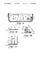
- FIG. 1is a top plan view of a domestic scale having a portion platform cut away to expose the novel bearing forms a part of my invention
- FIG. 2is fragmentary, front, elevational view of the scale of FIG. 1;
- FIG. 3is a sectional view taken on line 3--3 of FIG. 1;
- FIG. 4is a fragmentary, sectional view taken substantially on line 4--4 of FIG. 3;
- FIG. 5top plan view of the scale of FIG. 1 with the platform removed to expose the force collection levers and weight indicating mechanism;
- FIG. 7is an enlarged, fragmentary sectional view taken on lines 7--7 of FIG. 6;
- FIG. 8is a plan view of of a portion of the under side of the platform with only the lower right bearing member assembled thereto;
- FIG. 9is a fragmentary, sectional view taken on line 9--9 of FIG. 9;
- FIG. 10is a perspective view of the bearing member.
- FIG. 11a fragmentary sectional view taken on line 11--11 of FIG. 8.
- the scale 12includes a load support platform 14 and a base 16.
- the base 16as best shown in FIGS. 2, 3 and 5, includes a substantially flat horizontal base portion 16a and an upstanding peripheral wall 16b.
- the platform 14is substantially coextensive and spaced from the base 16 having a flat support portion 14a and a peripherally and downwardly extending flange 14b. As best shown in FIG. 3, the platform 14 extends beyond the base 16 with the peripheral flange 14b extending downwardly and overlapping the upwardly extending wall 16b on the base 16.
- the platform 14 and the base 16form an enclosure within which force collection levers 18 and an weighing mechanism 20 are located.
- the force collection leversinclude primary levers 18a and 18b and secondary levers 18c and 18d. All four of the levers 18a, 18b, 18c and 18d have their outermost ends resting in slots 16c formed in the corners and the upper edges of the walls 16b to provide bearing surfaces for the outer ends of the force levers 18a, 18b, 18c and 18d.
- each of the force leversincludes a downwardly facing V-shaped notch 22 which engages in the slot 16c and forms the bearing on the force lever and serves to locate the force lever against lengthwise displacement.
- the weighing mechanism 20it forms no part of the present invention and may include a mechanical mechanism utilizing a spring as disclosed in the drawings including FIGS. 5, 6 and 7 and described in detail in Hanssen U.S. Pat. No. 3,134,451, assigned to the same assignee as the present invention.
- the weighing mechanismcan be of the electronic strain gauge or pulse count variety as are well known in the domestic scale art.
- the weighing mechanism 20includes a spring 24 which is deformed and displaced by application of force to a plate 26 which is engaged by the ends 28 of the primary force levers 18a and 18b. The force levers 18a and 18b cause the plate 26 to be forced downwardly against the action of the spring 24.
- the amount of displacement of the plate 26is proportional to the weight applied to the platform 14 or to the force exerted by the levers 18a and 18b.
- This downward displacement of the plate 26is sensed through a lever 30 and a link 32, the link having a rack 32a formed thereon.
- the rack 32acooperates with a pinion 34 to rotate a shaft supporting an indicia bearing disk 36.
- the indicia bearing disk 36is visible through a window 14c in the platform 14.
- the windowis provided with an index line 38 which cooperates with the disk 36 to provide a weight reading as is well known in the art.
- Each bearing 42includes a somewhat channel-shaped column portion 42a and a base or stand portion made up of the flanges 42b, 42c and 42d.
- the oppositely extending flanges 42b and 42care formed with elongated slots 42e.
- the column portion 42ais formed with two spaced projections 42f between which is formed a slot 42g.
- the bearing members 42are mounted on the underside of the platform 14 as illustrated in FIGS. 1, 3 and 4 which show only one of the bearing members.
- the purpose of the slot 42g formed in the end of the downwardly extending column portion 42ais to receive the force lever as is shown in FIG. 4.
- the slot 42gis about thirty-thousandths of an inch (0.030) wider than the thickness of the force lever received therein, allowing some latitude for alignment and displacement. As best shown in FIG.
- each force leveris formed with an open, upwardly facing V-shaped notch or bearing recess 44 into which the end of the column 42a, and more particularly, the end of the slot 42g engages the force lever.
- the force applied through the bearing members 42must be vertical, causing rotational movement of the force collecting levers but may not include a twisting or lengthwise moment of force on the force levers or additional friction would be introduced to produce inaccuracies and inconsistent weight measurement.
- the bearing members 42are mounted to the under side of the platform 14 with a loose connection so that the bearing members 42 may be displaced in the horizontal direction while at the same time being maintained vertical.
- the bearing members 42are mounted to the platform 14 by tabs 46 formed integrally from the sheet metal member which forms the platform 14. The tabs 46 are shown in FIG.
- the amount of permitted movement either lengthwise of the force levers or transverse of the force leversis about 1/16" or 0.0625".
- the four bearing members 42may move lengthwise of the force levers to center themselves at the bottom of the notches 44 and also align themselves transversely of the levers so that no binding will occur as the force on the platform 14 is applied vertically through the bearings 42.
- the resultis a simple and inexpensive expedient to transmit the force from the platform to the force collecting levers providing a pure vertical application of forces to the levers while avoiding any twisting or lengthwise forces in the levers which might create friction in the bearings for the force levers 18a, 18b, 18c and 18d which would in turn introduce error in the measurements made by the scale.
- the bearing members 42are formed sheet metal members which are inexpensive and easy to manufacture.
- the tabs 46 which interconnect the bearing members 42 to the platform 14are formed integrally from the sheet metal of the platform and are inherently inexpensive to form and provide a simple assembly device.
Landscapes
- Physics & Mathematics (AREA)
- General Physics & Mathematics (AREA)
- Engineering & Computer Science (AREA)
- Mathematical Physics (AREA)
- Theoretical Computer Science (AREA)
- Force Measurement Appropriate To Specific Purposes (AREA)
Abstract
Description
Claims (9)
Priority Applications (1)
| Application Number | Priority Date | Filing Date | Title |
|---|---|---|---|
| US07/625,570US5133420A (en) | 1990-12-11 | 1990-12-11 | Bearing support for a scale platform |
Applications Claiming Priority (1)
| Application Number | Priority Date | Filing Date | Title |
|---|---|---|---|
| US07/625,570US5133420A (en) | 1990-12-11 | 1990-12-11 | Bearing support for a scale platform |
Publications (1)
| Publication Number | Publication Date |
|---|---|
| US5133420Atrue US5133420A (en) | 1992-07-28 |
Family
ID=24506692
Family Applications (1)
| Application Number | Title | Priority Date | Filing Date |
|---|---|---|---|
| US07/625,570Expired - LifetimeUS5133420A (en) | 1990-12-11 | 1990-12-11 | Bearing support for a scale platform |
Country Status (1)
| Country | Link |
|---|---|
| US (1) | US5133420A (en) |
Cited By (15)
| Publication number | Priority date | Publication date | Assignee | Title |
|---|---|---|---|---|
| EP0674159A1 (en)* | 1994-03-24 | 1995-09-27 | Eks International Ab | Scale, especially bathroom scale, and method for mounting thereof |
| US6585647B1 (en) | 1998-07-21 | 2003-07-01 | Alan A. Winder | Method and means for synthetic structural imaging and volume estimation of biological tissue organs |
| US6608260B2 (en) | 2001-09-21 | 2003-08-19 | Sunbeam Products, Inc. | Planetary weigh scale |
| US20040092849A1 (en)* | 2002-11-08 | 2004-05-13 | Talish Roger J. | Apparatuses and methods for therapeutically treating damaged tissues, bone fractures, osteopenia, or osteoporosis |
| US6932308B2 (en) | 2000-10-25 | 2005-08-23 | Exogen, Inc. | Transducer mounting assembly |
| US7108663B2 (en) | 1997-02-06 | 2006-09-19 | Exogen, Inc. | Method and apparatus for cartilage growth stimulation |
| US7211060B1 (en) | 1998-05-06 | 2007-05-01 | Exogen, Inc. | Ultrasound bandages |
| US20070260161A1 (en)* | 2002-11-08 | 2007-11-08 | Titi Trandafir | Apparatus and methods for therapeutically treating damaged tissues, bone fractures, osteopenia, or osteoporosis |
| US7410469B1 (en) | 1999-05-21 | 2008-08-12 | Exogen, Inc. | Apparatus and method for ultrasonically and electromagnetically treating tissue |
| US7429249B1 (en) | 1999-06-14 | 2008-09-30 | Exogen, Inc. | Method for cavitation-induced tissue healing with low intensity ultrasound |
| US7429248B1 (en) | 2001-08-09 | 2008-09-30 | Exogen, Inc. | Method and apparatus for controlling acoustic modes in tissue healing applications |
| US7628764B2 (en) | 1997-02-14 | 2009-12-08 | Exogen, Inc. | Ultrasonic treatment for wounds |
| US7789841B2 (en) | 1997-02-06 | 2010-09-07 | Exogen, Inc. | Method and apparatus for connective tissue treatment |
| US8603017B2 (en) | 2005-03-07 | 2013-12-10 | American Medical Innovations, L.L.C. | Vibrational therapy assembly for treating and preventing the onset of deep venous thrombosis |
| US8795210B2 (en) | 2006-07-11 | 2014-08-05 | American Medical Innovations, L.L.C. | System and method for a low profile vibrating plate |
Citations (10)
| Publication number | Priority date | Publication date | Assignee | Title |
|---|---|---|---|---|
| US349521A (en)* | 1886-09-21 | Automatic weighing mechanism for elevators | ||
| US3134451A (en)* | 1962-03-14 | 1964-05-26 | Hanson Scale Co | Platform type bathroom scale |
| US3193034A (en)* | 1961-01-06 | 1965-07-06 | Continental Scale Corp | Weighing scale |
| US3844365A (en)* | 1972-03-08 | 1974-10-29 | B Ek | Platform-type scale |
| DE2364293A1 (en)* | 1973-12-22 | 1975-06-26 | Stube Fa Richard | Bathroom scale with frame having levers - which are at four corners operating against a resetting force and supporting a platform |
| US4452326A (en)* | 1982-07-26 | 1984-06-05 | Tricolor Corporation | Corner bearing assembly for platform scale |
| US4456086A (en)* | 1979-08-01 | 1984-06-26 | The United States Of America As Represented By The Secretary Of The Navy | Integrated wheelchair and ambulator |
| US4458771A (en)* | 1982-09-20 | 1984-07-10 | Tricolor Corporation | Corner post mount for weighing scale |
| US4521658A (en)* | 1984-01-16 | 1985-06-04 | Amana Refrigeration, Inc. | Microwave oven scale apparatus |
| US4609069A (en)* | 1984-08-14 | 1986-09-02 | Yasui Sangyo, Ltd. | Silencer for a pneumatically driven hydraulic jack |
- 1990
- 1990-12-11USUS07/625,570patent/US5133420A/ennot_activeExpired - Lifetime
Patent Citations (10)
| Publication number | Priority date | Publication date | Assignee | Title |
|---|---|---|---|---|
| US349521A (en)* | 1886-09-21 | Automatic weighing mechanism for elevators | ||
| US3193034A (en)* | 1961-01-06 | 1965-07-06 | Continental Scale Corp | Weighing scale |
| US3134451A (en)* | 1962-03-14 | 1964-05-26 | Hanson Scale Co | Platform type bathroom scale |
| US3844365A (en)* | 1972-03-08 | 1974-10-29 | B Ek | Platform-type scale |
| DE2364293A1 (en)* | 1973-12-22 | 1975-06-26 | Stube Fa Richard | Bathroom scale with frame having levers - which are at four corners operating against a resetting force and supporting a platform |
| US4456086A (en)* | 1979-08-01 | 1984-06-26 | The United States Of America As Represented By The Secretary Of The Navy | Integrated wheelchair and ambulator |
| US4452326A (en)* | 1982-07-26 | 1984-06-05 | Tricolor Corporation | Corner bearing assembly for platform scale |
| US4458771A (en)* | 1982-09-20 | 1984-07-10 | Tricolor Corporation | Corner post mount for weighing scale |
| US4521658A (en)* | 1984-01-16 | 1985-06-04 | Amana Refrigeration, Inc. | Microwave oven scale apparatus |
| US4609069A (en)* | 1984-08-14 | 1986-09-02 | Yasui Sangyo, Ltd. | Silencer for a pneumatically driven hydraulic jack |
Cited By (25)
| Publication number | Priority date | Publication date | Assignee | Title |
|---|---|---|---|---|
| US5721400A (en)* | 1994-03-24 | 1998-02-24 | Eks International Ab | Scale with lever mechanism and method for mounting components |
| EP0674159A1 (en)* | 1994-03-24 | 1995-09-27 | Eks International Ab | Scale, especially bathroom scale, and method for mounting thereof |
| US7108663B2 (en) | 1997-02-06 | 2006-09-19 | Exogen, Inc. | Method and apparatus for cartilage growth stimulation |
| US8123707B2 (en) | 1997-02-06 | 2012-02-28 | Exogen, Inc. | Method and apparatus for connective tissue treatment |
| US7789841B2 (en) | 1997-02-06 | 2010-09-07 | Exogen, Inc. | Method and apparatus for connective tissue treatment |
| US7628764B2 (en) | 1997-02-14 | 2009-12-08 | Exogen, Inc. | Ultrasonic treatment for wounds |
| US7211060B1 (en) | 1998-05-06 | 2007-05-01 | Exogen, Inc. | Ultrasound bandages |
| US6585647B1 (en) | 1998-07-21 | 2003-07-01 | Alan A. Winder | Method and means for synthetic structural imaging and volume estimation of biological tissue organs |
| US7410469B1 (en) | 1999-05-21 | 2008-08-12 | Exogen, Inc. | Apparatus and method for ultrasonically and electromagnetically treating tissue |
| US7429249B1 (en) | 1999-06-14 | 2008-09-30 | Exogen, Inc. | Method for cavitation-induced tissue healing with low intensity ultrasound |
| US6932308B2 (en) | 2000-10-25 | 2005-08-23 | Exogen, Inc. | Transducer mounting assembly |
| US7429248B1 (en) | 2001-08-09 | 2008-09-30 | Exogen, Inc. | Method and apparatus for controlling acoustic modes in tissue healing applications |
| US6608260B2 (en) | 2001-09-21 | 2003-08-19 | Sunbeam Products, Inc. | Planetary weigh scale |
| US20070225626A1 (en)* | 2002-11-08 | 2007-09-27 | Krompasick Donald E | Apparatus and method for therapeutically treating damaged tissues, bone fractures, osteopenia or osteoporosis |
| US20070260161A1 (en)* | 2002-11-08 | 2007-11-08 | Titi Trandafir | Apparatus and methods for therapeutically treating damaged tissues, bone fractures, osteopenia, or osteoporosis |
| US6884227B2 (en) | 2002-11-08 | 2005-04-26 | Juvent, Inc. | Apparatuses and methods for therapeutically treating damaged tissues, bone fractures, osteopenia, or osteoporosis |
| US7207955B2 (en) | 2002-11-08 | 2007-04-24 | Juvent, Inc. | Apparatus and method for therapeutically treating damaged tissues, bone fractures, osteopenia or osteoporosis |
| US20060229536A1 (en)* | 2002-11-08 | 2006-10-12 | Exogen, Inc. | Apparatus and method for therapeutically treating damaged tissues, bone fractures, osteopenia or osteoporosis |
| US20040092849A1 (en)* | 2002-11-08 | 2004-05-13 | Talish Roger J. | Apparatuses and methods for therapeutically treating damaged tissues, bone fractures, osteopenia, or osteoporosis |
| US20050148911A1 (en)* | 2002-11-08 | 2005-07-07 | Exogen Inc. | Apparatuses and methods for therapeuticaly treating damaged tissues, bone fractures, osteopenia or osteoporosis |
| US7985191B2 (en)* | 2002-11-08 | 2011-07-26 | American Medical Innovations, L.L.C. | Apparatus and methods for therapeutically treating damaged tissues, bone fractures, osteopenia, or osteoporosis |
| US8114036B2 (en) | 2002-11-08 | 2012-02-14 | American Medical Innovations, L.L.C. | Apparatus and method for therapeutically treating damaged tissues, bone fractures, osteopenia or osteoporosis |
| US7094211B2 (en) | 2002-11-08 | 2006-08-22 | Krompasick Donald E | Apparatuses and methods for therapeutically treating damaged tissues, bone fractures, osteopenia, or osteoporosis |
| US8603017B2 (en) | 2005-03-07 | 2013-12-10 | American Medical Innovations, L.L.C. | Vibrational therapy assembly for treating and preventing the onset of deep venous thrombosis |
| US8795210B2 (en) | 2006-07-11 | 2014-08-05 | American Medical Innovations, L.L.C. | System and method for a low profile vibrating plate |
Similar Documents
| Publication | Publication Date | Title |
|---|---|---|
| US5133420A (en) | Bearing support for a scale platform | |
| US4387777A (en) | Calorie counting method and apparatus | |
| EP0136118A2 (en) | Load cell with shift adjustment and scale | |
| US3193034A (en) | Weighing scale | |
| US4452326A (en) | Corner bearing assembly for platform scale | |
| US7214892B2 (en) | Scale lever assembly | |
| US4381826A (en) | Weighing scale of unitary construction | |
| US4150729A (en) | Strain gauge flexure isolated weighing scale | |
| US4273204A (en) | Capacitive force load cell for weighing scale | |
| US4836316A (en) | Bath scale | |
| US3709310A (en) | Load indicating apparatus with hysteresis correction | |
| US4691794A (en) | Weight scales and strain gauge assemblies useable therein | |
| US2098845A (en) | Weighing scale | |
| JPS5827023A (en) | Register | |
| US3844365A (en) | Platform-type scale | |
| EP0194363A1 (en) | Improved rocking scale | |
| US4832142A (en) | Electronic scale apparatus | |
| US2582017A (en) | Balance | |
| US2716546A (en) | Weighing mechanisms | |
| EP0020030A1 (en) | Weigh head assembly | |
| US2224327A (en) | Weighing scale | |
| US3405775A (en) | Weighing mechanism | |
| CA1216312A (en) | Load cell apparatus | |
| US2788963A (en) | Weighing scales | |
| CA1273369A (en) | Weighing element for a weighing apparatus |
Legal Events
| Date | Code | Title | Description |
|---|---|---|---|
| AS | Assignment | Owner name:SUNBEAM CORPORATION, ILLINOIS Free format text:ASSIGNMENT OF ASSIGNORS INTEREST.;ASSIGNOR:SMITH, RODNEY;REEL/FRAME:005533/0922 Effective date:19901205 | |
| STCF | Information on status: patent grant | Free format text:PATENTED CASE | |
| FPAY | Fee payment | Year of fee payment:4 | |
| AS | Assignment | Owner name:SUNBEAM PRODUCTS, INC., FLORIDA Free format text:CHANGE OF NAME;ASSIGNOR:SUNBEAM CORPORATION;REEL/FRAME:009297/0347 Effective date:19950512 | |
| FPAY | Fee payment | Year of fee payment:8 | |
| AS | Assignment | Owner name:FIRST UNION NATIONAL BANK, AS ADMINISTRATIVE AGENT Free format text:CONDITIONL ASSIGNMENT OF AND SECURITY INTEREST IN PATENT RIGHTS;ASSIGNOR:SUNBEAM PRODUCTS, INC. (DE CORPORATION);REEL/FRAME:011019/0138 Effective date:20001005 | |
| AS | Assignment | Owner name:FIRST UNION NATIONAL BANK, AS ADMINISTRATIVE AGENT Free format text:SECURITY INTEREST;ASSIGNOR:SUNBEAM PRODUCTS, INC. (DE CORPORATION);REEL/FRAME:011111/0172 Effective date:20000929 | |
| AS | Assignment | Owner name:GENERAL ELECTRIC CAPITAL CORPORATION, GEORGIA Free format text:INTELLECTUAL PROPERTY SECURITY AGREEMENT;ASSIGNORS:COLEMAN COMPANY, INC., THE;COLEMAN POWERMATE, INC.;BRK BRANDS, INC.;AND OTHERS;REEL/FRAME:014027/0767 Effective date:20021213 | |
| FPAY | Fee payment | Year of fee payment:12 |