US5131397A - Imaging system for producing ultrasonic images and insonifier for such systems - Google Patents
Imaging system for producing ultrasonic images and insonifier for such systemsDownload PDFInfo
- Publication number
- US5131397A US5131397AUS07/579,010US57901090AUS5131397AUS 5131397 AUS5131397 AUS 5131397AUS 57901090 AUS57901090 AUS 57901090AUS 5131397 AUS5131397 AUS 5131397A
- Authority
- US
- United States
- Prior art keywords
- insonifier
- catheter
- disposed
- image
- sonic
- Prior art date
- Legal status (The legal status is an assumption and is not a legal conclusion. Google has not performed a legal analysis and makes no representation as to the accuracy of the status listed.)
- Expired - Fee Related
Links
- 238000003384imaging methodMethods0.000titleclaimsabstractdescription12
- 238000002604ultrasonographyMethods0.000claimsabstractdescription10
- 210000000056organAnatomy0.000claimsdescription14
- 230000005540biological transmissionEffects0.000claimsdescription10
- 230000002792vascularEffects0.000claimsdescription6
- 210000001367arteryAnatomy0.000abstractdescription9
- 239000002131composite materialSubstances0.000abstract1
- 238000000034methodMethods0.000description7
- 238000002592echocardiographyMethods0.000description6
- 239000012530fluidSubstances0.000description4
- 238000012285ultrasound imagingMethods0.000description4
- 210000003484anatomyAnatomy0.000description3
- 239000008280bloodSubstances0.000description3
- 210000004369bloodAnatomy0.000description3
- 230000003902lesionEffects0.000description3
- 239000004020conductorSubstances0.000description2
- 239000000976inkSubstances0.000description2
- 230000033001locomotionEffects0.000description2
- 230000007246mechanismEffects0.000description2
- 239000013307optical fiberSubstances0.000description2
- 230000005855radiationEffects0.000description2
- 206010003210ArteriosclerosisDiseases0.000description1
- 244000273618Sphenoclea zeylanicaSpecies0.000description1
- 208000011775arteriosclerosis diseaseDiseases0.000description1
- 230000001427coherent effectEffects0.000description1
- 210000004351coronary vesselAnatomy0.000description1
- 238000001514detection methodMethods0.000description1
- 238000003745diagnosisMethods0.000description1
- 201000010099diseaseDiseases0.000description1
- 208000037265diseases, disorders, signs and symptomsDiseases0.000description1
- 230000009977dual effectEffects0.000description1
- 230000003760hair shineEffects0.000description1
- 208000014674injuryDiseases0.000description1
- 238000003780insertionMethods0.000description1
- 230000037431insertionEffects0.000description1
- 230000002452interceptive effectEffects0.000description1
- 238000002608intravascular ultrasoundMethods0.000description1
- 210000003127kneeAnatomy0.000description1
- 239000007788liquidSubstances0.000description1
- 239000000463materialSubstances0.000description1
- 230000004048modificationEffects0.000description1
- 238000012986modificationMethods0.000description1
- 230000000414obstructive effectEffects0.000description1
- 229920001296polysiloxanePolymers0.000description1
- 230000008569processEffects0.000description1
- 230000009467reductionEffects0.000description1
- 230000004044responseEffects0.000description1
- 230000002966stenotic effectEffects0.000description1
- 239000000758substrateSubstances0.000description1
- 238000001356surgical procedureMethods0.000description1
- 230000008733traumaEffects0.000description1
- 210000003462veinAnatomy0.000description1
- 230000000007visual effectEffects0.000description1
- XLYOFNOQVPJJNP-UHFFFAOYSA-NwaterSubstancesOXLYOFNOQVPJJNP-UHFFFAOYSA-N0.000description1
Images
Classifications
- A—HUMAN NECESSITIES
- A61—MEDICAL OR VETERINARY SCIENCE; HYGIENE
- A61B—DIAGNOSIS; SURGERY; IDENTIFICATION
- A61B5/00—Measuring for diagnostic purposes; Identification of persons
- A61B5/68—Arrangements of detecting, measuring or recording means, e.g. sensors, in relation to patient
- A61B5/6801—Arrangements of detecting, measuring or recording means, e.g. sensors, in relation to patient specially adapted to be attached to or worn on the body surface
- A61B5/684—Indicating the position of the sensor on the body
- A61B5/6842—Indicating the position of the sensor on the body by marking the skin
- A—HUMAN NECESSITIES
- A61—MEDICAL OR VETERINARY SCIENCE; HYGIENE
- A61B—DIAGNOSIS; SURGERY; IDENTIFICATION
- A61B8/00—Diagnosis using ultrasonic, sonic or infrasonic waves
- A61B8/08—Clinical applications
- A61B8/0833—Clinical applications involving detecting or locating foreign bodies or organic structures
- A61B8/0841—Clinical applications involving detecting or locating foreign bodies or organic structures for locating instruments
- A—HUMAN NECESSITIES
- A61—MEDICAL OR VETERINARY SCIENCE; HYGIENE
- A61B—DIAGNOSIS; SURGERY; IDENTIFICATION
- A61B8/00—Diagnosis using ultrasonic, sonic or infrasonic waves
- A61B8/12—Diagnosis using ultrasonic, sonic or infrasonic waves in body cavities or body tracts, e.g. by using catheters
- A—HUMAN NECESSITIES
- A61—MEDICAL OR VETERINARY SCIENCE; HYGIENE
- A61B—DIAGNOSIS; SURGERY; IDENTIFICATION
- A61B8/00—Diagnosis using ultrasonic, sonic or infrasonic waves
- A61B8/44—Constructional features of the ultrasonic, sonic or infrasonic diagnostic device
- A61B8/4444—Constructional features of the ultrasonic, sonic or infrasonic diagnostic device related to the probe
- A61B8/445—Details of catheter construction
- A—HUMAN NECESSITIES
- A61—MEDICAL OR VETERINARY SCIENCE; HYGIENE
- A61B—DIAGNOSIS; SURGERY; IDENTIFICATION
- A61B8/00—Diagnosis using ultrasonic, sonic or infrasonic waves
- A61B8/44—Constructional features of the ultrasonic, sonic or infrasonic diagnostic device
- A61B8/4444—Constructional features of the ultrasonic, sonic or infrasonic diagnostic device related to the probe
- A61B8/4461—Features of the scanning mechanism, e.g. for moving the transducer within the housing of the probe
Definitions
- the present inventionrelates to a system for determining the location and orientation of intravascular ultrasound images relative to the external anatomy of the organ being studied and an insonifier that is especially useful in the system.
- Ultrasound imaging cathetersprovide for cross-sectional views of lumenal structures and are especially useful in the diagnosis of obstructive diseases that affect the vascular system in humans. Although there are various ways to accomplish this type of imaging, most ultrasound imaging catheters employ mechanisms to direct scanning beams of ultrasonic energy into the area being studied and receive the return echoes from these beams in a sequence for display on a cathode ray tube (CRT). Equipment that generates the sound and receives the return echoes so that the sound can be displayed on the CRT is well known.
- CTRcathode ray tube
- One of the more troublesome problems encountered during medical examinations using ultrasound imaging cathetersis the difficulty encountered in subsequently returning to the exact same site and with the same orientation of the tip if a second examination of the same area of the organ being studied is required.
- the orientation of the ultrasound image displayed on the CRTmight bear no relationship to the external anatomy of the catheterized body because insertion of the catheter subjects it to twists, bends and other conditions that make the orientation of the tip difficult or impossible to predict accurately.
- the position of the cathetercan be determined generally by X-ray, the physician cannot identify its orientation easily from the image on the CRT, that is whether the image being transmitted from the catheter to the CRT is "up", "down” or somewhere in between.
- Such devicesinclude an acoustical output pulse generator and a receiver to detect the pulses in the form of echoes. From surface discontinuities in the form of impedance mismatches and the ultrasonic frequency of the precise part of the body at which the pulse is directed, an image of the portion of the body being examined can be displayed on the CRT.
- the pulsesprovide information about the tissue through which the pulses travel and the relative timing of the return pulses corresponds to impedance discontinuities which provide information on the thickness of various types of tissues at the specific location at which the initial pulse is directed.
- the relative strength of the echoesreflects the differences in impedance between adjacent boundaries of different types of tissues and therefore the difference in densities of the material.
- the acoustical techniquecan therefore be used to ascribe the character of tissues from which the echoes are received.
- the information that is generatedis particularly useful in procedures such as removing arteriosclerotic plaque deposits which restrict the flow of blood in coronary arteries.
- the plaque depositsBy moving the tip of the catheter to the location that is being studied, the plaque deposits can be identified.
- the obstructionscan be removed.
- techniquessuch as laser radiation can be used in which an optical fiber or fibers are used to vaporize the plaque through known techniques.
- the plaquecan thus be removed without the trauma associated with surgery.
- Such proceduresrequire specific knowledge of the location, thickness and density of the plaque to be removed in order to minimize damage to the arterial wall of the diseased site.
- Fairly complicated mechanisms to identify the site preciselyinclude x-ray detection, the use of external magnetic fields or systems and methods for collecting sets of data derived from acoustical signals generated at a corresponding plurality of locations at the diseased site and relating the sets of data with respect to the relative locations from which they are obtained so that they can be used to create a coherent image of the diseased site.
- the Martinelli et al apparatusthat includes a catheter which is partially inserted into the body so that the tip is positioned relative to the preselected site and imaging data relating to the internal features can be acoustically determined by moving the tip to a plurality of positions relative to the site.
- An acoustical signalcan be generated when the tip is in each of the positions.
- the acoustical energy responsive to the acoustical signal at each of the positionsis sensed so as to create a set of data and the location is sensed magnetically in each of the positions.
- the sensed data and the respective positions from which each was obtainedis related to create an image of the internal features of the organ being studied.
- the creation of an image of an arteriosclerosis lesion on the interior wall of an arteryis accomplished by longitudinally and rotationally displacing the catheter tip (and thus the transducer in the catheter tip) through the diseased site so that a set of return pulses is obtained from a series of locations within the diseased site.
- the set of return pulses obtained from each angular and longitudinal position of the cathetercan then be related to one another so as to create relative spatial information of the structure of the portions of the diseased site represented by sets of return pulses based on the known signatures of various types of tissue encountered in such diseased sites.
- the orientation of the tip of the catheteris accomplished by sensing the orientation of magnetic fields. The equipment necessary to provide for such views and their orientations is complicated and bulky, at best.
- a novel imaging systemincluding a catheter tip having transducers housed inside and an insonifier for detecting both the position and orientation of a catheter tip when it has been inserted into an organ or canal of the body.
- the system of my inventioncan display images of cross-sections of the organ or canal on a CRT and the CRT can also display the orientation of the tip simultaneously.
- One part of the systemincludes a catheter which has a longitudinal axis, a tip and a proximal end. Sonic image generating means and an image sensing means in the form of transducers are disposed in the tip of the catheter.
- An insonifierforms another part of the system and is placed externally to the portion of the body being examined.
- the insonifierincludes a sonic generator which produces sound at a frequency that can be received by the image sensing means housed in the catheter tip.
- the insonifierhas two modes of operation.
- a wide angle of ultrasound energyis generated at a frequency that can be received and displayed by the image sensing means which is housed in the catheter that is placed inside the body.
- the wide angle ultrasound from the insonifieris urged against the outside of the body in the general area of where the catheter tip is thought to be.
- the representation of the wide angle soundwill appear on the CRT and provide an interference pattern adjacent where the catheter tip is located.
- the sonic generator in the catheteris sending its own signals to the CRT.
- the ultrasound of the insonifieris focused so as to determine precisely where the catheter tip is located.
- the orientation of the catheter tipbecomes evident on the CRT through the signal that is generated by the insonifier and detected by the image sensing means.
- the pattern from the insonifiershows on the CRT because the externally applied field can be picked up by the transducer within the catheter that is disposed within the patient.
- the patternis brightest when the insonifier is in closest proximity to the tip of the catheter.
- the patternalso has a directional characteristic which is due to the manner in which the sonic energy propagates through the tissue.
- the patternforms a viewable image on the CRT that correctly indicates the orientation of the catheter tip relative to the insonifier.
- the most efficient transfer of sonic energy from the insonifier to the image sensing meansoccurs when the two devices face each other.
- the viewable image of the insonifiercan be a bright light which shines to the area of the image and corresponds to the direction of the insonifier. If the display imaging system, the CRT, is equipped with a means to rotate image electronically, then the orientation (up, down, etc.) can be displayed correctly and repeatedly together with a knowledge of the exact position of the catheter tip.
- a marking devicecan be added to the insonifier to mark and identify permanently where the catheter is relative to the outside of the body.
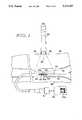
- FIG. 1is a view of the system, partially in cross section, according to the present invention including a catheter disposed in an artery, an insonifier and related electro-acoustical transmission and display devices.
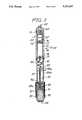
- FIG. 2is a cross-sectional view of an insonifier having a dual range acoustical transmission that can be used with the system of the present invention.
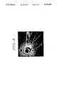
- FIG. 3is a view of a sonogram as displayed on a an ultrasound imaging console cathode ray tube whereby the orientation of the catheter can be determined by an interference signal generated by the insonifier.
- the catheter 20is shown disposed within an artery 28 with the tip section 30 positioned opposite a stenotic lesion shown at 32.
- a transducer 34 disposed in the tip section 30is positioned to transmit a beam of acoustical pulses from tip section 30 transversely to the longitudinal axis 22 of catheter 20 preferably through a window 30a. Sonic pulses are generated in response to electrical pulses transmitted along a set of insulated electrical conductors (not shown) that are disposed within a cable 50.
- the generation and receiving of soundcan be produced by the transducer 34 which can be a single transducer that is switched back and forth between a transmission mode and a receiving mode.
- a set of transducers 34 and 34ais used, one connected for transmission and the other for receiving.
- the acoustical pulseswill be transmitted along a radius of transmission 38 and pass into a lesion 32 and the underlining arterial wall 28.
- Acoustical echos, deflected by impedance mismatches of the various surfaces of the different substratesreturn to the transducer 34 (or 34a) and are converted to electrical signals which are transmitted through the conductors in the cable 50.
- the transduceris preferably disposed within the tip section 30 and can rotate about the longitudinal axis 22. Such rotation is accomplished by turning cable 50 with a motor 51. Motor 51 and the use of a transducer disposed in a catheter on a rotatable cable is well known.
- a motor controllerpositions the transducer 34 for the next scan line.
- a transmit pulserdrives the ultrasound transducer.
- the transducer 34converts the electrical energy to acoustical energy and emits a sound wave at a predetermined frequency.
- the sound wavereflects off the section 32 of the organ being studied.
- a portion of the sound wavereturns to the transducer 34 (or to a second transducer 34a placed in close proximity to the first one).
- the acoustical energyis reconverted to electrical energy.
- a receiver in the unit 53takes a waveform of the electrical energy and gates out the originally transmitted pulse.
- the remaining informationis processed so that signal amplitude is converted to intensity, and time from the originally transmitted pulse and the signal is translated to distance.
- the brightness and distance informationis transmitted into a vector/scan connector which, together with the position information from the motor controller, converts the polar coordinates to rectangular coordinates for a raster monitor. The process is repeated many thousands of times per second to form a real time, two dimensional ultrasound image of the subject being studied and for display on a CRT 53a and recording.
- an interfering second image generated by the insonifier 55is simultaneously displayed on the CRT 53a.
- the sonic emissions for the second imageare produced by the insonifier 55 and are shown as dotted lines 56.
- an wide angle signalis produced by the insonifier 55 which enables the user to apply the device in the general area of the body 46 where the catheter tip 30 is thought to be.
- the emission from the device 55can be focused so as to produce a narrower signal thereby to provide a bright area on the CRT which will more closely correspond to the relative position of the device 55 and the tip 30 of the catheter. Then, with an appropriate adjustment, the "top" of the organ being examined can be adjusted on the CRT as desired.
- there is no electrical connection between the unit 53 and the insonifier 55although in some instances it may be desirable to use a wand that is pulsed from a common pulse generator in unit 53 for supplying a pulse to both the insonifier 55 and the transducer 34.
- the signal from the insonifier 55should preferably be pulsed so as to conserve power since the insonifier 55 is battery powered and continuous operation of the insonifier 55 will quickly reduce its output. In those cases where it is found to be more efficacious to use pulses in each transducer generated from a single source, an electrical connection is required between the insonifier 55 and unit 53.
- the preferred embodiment of the insonifierhas a tubular barrel with an operating end 82 and an examining end 84.
- the operating end 82is connected to the examining end 84 by means of threads 79 and a male to female fitting.
- An on/off button 63slides within a collar 65 that is attached, preferably by threads, to the end of operating end 82.
- the collar 65can be unscrewed to enable the user to reach a battery set 67 for their replacement.
- Button 63is normally biased in the "off" position by a spring 71, as is conventional with many battery operated devices.
- the battery set 67sits upon a spring 73 that rests on a wall 76.
- a chamber 74 disposed within the operating end 82houses a conventional pulse generator circuit disposed on a circuit board 75. Electrical connection between the battery set 67 and the pulse generator circuit board 75 is accomplished through wire 77.
- a coaxial wire 81extends from the circuit board 75 and the upper chamber 74 through a wall 78 to the top of a plunger 83.
- Coaxial cable 81is of a sufficient length to provide for motion of the plunger 83 along the axis of a lower chamber 85.
- the plunger 83has a knob 83a that extends outwardly from lower chamber 85 and is moveable in a slot 85a.
- a hollow stem 87extends from plunger 83 and receives the coaxial cable 81.
- a support plate 89preferably supported by knees 89a, is disposed on the end of the stem 87 and within the examining end 84 of the insonifier.
- a transducer 91is disposed on the support plate 89 and is connected to coaxial cable 81.
- the tip of examining end 84forms a fluid holding chamber 92 and is filled with fluid 93 commonly used for the transmission of sound. Fluids may be, for example, water, oil or silicones. To keep the fluids within the chamber 92, stem 87 rides within an 0-ring seal 90 which prevents leaking. A window 95, generally formed of plastic that is transparent to sonic waves, is disposed in the tip.
- Movement of the plunger 83 relative to window 95moves transducer 91 relative to the window 95.
- the transducer 91When the transducer 91 is most distantly positioned relative to window 95, the sonic radiation is most sharply in focus. As it is moved nearer to the window 95, the focus is reduced, but the area that is being irradiated is wider.
- the insonifier 55can be moved around over a wide area with the transducer 91 nearest the window 95 until the interference signal shows on the CRT. Then the focus can be narrowed by moving the transducer 91 away from the window 95 to determine the precise location of the catheter tip.
- a marking sleeve 97is used that is slidably disposed around the end of the examining end 84.
- the marking sleeve 97can include a felt tip 97a with an ink supply.
- the sleeve 97can be moved along the examining end 85 and can mark the precise location on the skin for subsequent use.
- Conventional marking inkscan be used at the end of the sleeve 97 to accomplish the marking.
- FIG. 3a view is shown of an interference pattern overlaying a typical sonogram of an artery.
- the circular dark area at the centeris the lumen of the catheter.
- the circular bright area surrounding the dark areais the wall of the catheter.
- To the right of the bright area(between 12 and 5 o'clock) is a dark section that is the portion of the artery carrying blood and not occupied by the catheter.
- the walls of the arteryare delineated as the line between the blood-containing dark section and the bright area surrounding it.
- a circular dark areais shown at 12 o'clock. This area represents a vein that is adjacent to the artery.
- the generally radial bright lines at 12, 1 and 3 o'clockare the interference pattern generated by the insonifier.
- the interference patternWith this visual representation of the interference pattern, it is possible for the operator to establish with certainty the orientation of the catheter in the artery being examined. With additional reduction of the focus of the insonifier, the interference pattern can be narrowed, as desired, or it can be converted electronically to an indicator such as an arrow.
Landscapes
- Life Sciences & Earth Sciences (AREA)
- Health & Medical Sciences (AREA)
- Surgery (AREA)
- Physics & Mathematics (AREA)
- Veterinary Medicine (AREA)
- Pathology (AREA)
- Public Health (AREA)
- Engineering & Computer Science (AREA)
- Biomedical Technology (AREA)
- Heart & Thoracic Surgery (AREA)
- Medical Informatics (AREA)
- Molecular Biology (AREA)
- Biophysics (AREA)
- Animal Behavior & Ethology (AREA)
- General Health & Medical Sciences (AREA)
- Radiology & Medical Imaging (AREA)
- Nuclear Medicine, Radiotherapy & Molecular Imaging (AREA)
- Ultra Sonic Daignosis Equipment (AREA)
Abstract
Description
The present invention relates to a system for determining the location and orientation of intravascular ultrasound images relative to the external anatomy of the organ being studied and an insonifier that is especially useful in the system.
1. Background of the Invention
Ultrasound imaging catheters provide for cross-sectional views of lumenal structures and are especially useful in the diagnosis of obstructive diseases that affect the vascular system in humans. Although there are various ways to accomplish this type of imaging, most ultrasound imaging catheters employ mechanisms to direct scanning beams of ultrasonic energy into the area being studied and receive the return echoes from these beams in a sequence for display on a cathode ray tube (CRT). Equipment that generates the sound and receives the return echoes so that the sound can be displayed on the CRT is well known.
One of the more troublesome problems encountered during medical examinations using ultrasound imaging catheters is the difficulty encountered in subsequently returning to the exact same site and with the same orientation of the tip if a second examination of the same area of the organ being studied is required. When the second examination of the organ is necessary the orientation of the ultrasound image displayed on the CRT might bear no relationship to the external anatomy of the catheterized body because insertion of the catheter subjects it to twists, bends and other conditions that make the orientation of the tip difficult or impossible to predict accurately. Thus, although the position of the catheter can be determined generally by X-ray, the physician cannot identify its orientation easily from the image on the CRT, that is whether the image being transmitted from the catheter to the CRT is "up", "down" or somewhere in between.
Knowledge of the "up/down" positioning is important especially when a sequence of ultrasound images is prepared for display in a series so as to provide images that, when grouped together, can generate an approximation of a three dimensional depiction of the organ being studied.
2. Description of the Prior Art
Devices for using acoustical pulses to generate echo sounds relating to the internal and external features of various parts of the body have been known and described in the prior art. Martinelli et al, U.S. Pat. No. 4,821,731, describes an electro-acoustical transducer device positioned on the tip of a catheter. The transducer device can be inserted into a liquid filled body canal or cavity. The catheter is moved into position at a particular site in the body and the transducer generates acoustical pulses in the directions of interest which can be displayed on a CRT.
Such devices include an acoustical output pulse generator and a receiver to detect the pulses in the form of echoes. From surface discontinuities in the form of impedance mismatches and the ultrasonic frequency of the precise part of the body at which the pulse is directed, an image of the portion of the body being examined can be displayed on the CRT. The pulses provide information about the tissue through which the pulses travel and the relative timing of the return pulses corresponds to impedance discontinuities which provide information on the thickness of various types of tissues at the specific location at which the initial pulse is directed. The relative strength of the echoes reflects the differences in impedance between adjacent boundaries of different types of tissues and therefore the difference in densities of the material. The acoustical technique can therefore be used to ascribe the character of tissues from which the echoes are received.
The information that is generated is particularly useful in procedures such as removing arteriosclerotic plaque deposits which restrict the flow of blood in coronary arteries. By moving the tip of the catheter to the location that is being studied, the plaque deposits can be identified. When the sites of the plaque or other irregularities are determined, the obstructions can be removed. Frequently, techniques such as laser radiation can be used in which an optical fiber or fibers are used to vaporize the plaque through known techniques. The plaque can thus be removed without the trauma associated with surgery. Such procedures, however, require specific knowledge of the location, thickness and density of the plaque to be removed in order to minimize damage to the arterial wall of the diseased site.
Fairly complicated mechanisms to identify the site precisely have been disclosed and include x-ray detection, the use of external magnetic fields or systems and methods for collecting sets of data derived from acoustical signals generated at a corresponding plurality of locations at the diseased site and relating the sets of data with respect to the relative locations from which they are obtained so that they can be used to create a coherent image of the diseased site.
Exemplary of such systems is the Martinelli et al apparatus that includes a catheter which is partially inserted into the body so that the tip is positioned relative to the preselected site and imaging data relating to the internal features can be acoustically determined by moving the tip to a plurality of positions relative to the site. An acoustical signal can be generated when the tip is in each of the positions. The acoustical energy responsive to the acoustical signal at each of the positions is sensed so as to create a set of data and the location is sensed magnetically in each of the positions. The sensed data and the respective positions from which each was obtained is related to create an image of the internal features of the organ being studied.
In the prior art system, the creation of an image of an arteriosclerosis lesion on the interior wall of an artery is accomplished by longitudinally and rotationally displacing the catheter tip (and thus the transducer in the catheter tip) through the diseased site so that a set of return pulses is obtained from a series of locations within the diseased site. The set of return pulses obtained from each angular and longitudinal position of the catheter can then be related to one another so as to create relative spatial information of the structure of the portions of the diseased site represented by sets of return pulses based on the known signatures of various types of tissue encountered in such diseased sites. The orientation of the tip of the catheter is accomplished by sensing the orientation of magnetic fields. The equipment necessary to provide for such views and their orientations is complicated and bulky, at best.
According to the present invention, I have discovered a novel imaging system including a catheter tip having transducers housed inside and an insonifier for detecting both the position and orientation of a catheter tip when it has been inserted into an organ or canal of the body. The system of my invention can display images of cross-sections of the organ or canal on a CRT and the CRT can also display the orientation of the tip simultaneously.
One part of the system includes a catheter which has a longitudinal axis, a tip and a proximal end. Sonic image generating means and an image sensing means in the form of transducers are disposed in the tip of the catheter. An insonifier forms another part of the system and is placed externally to the portion of the body being examined. The insonifier includes a sonic generator which produces sound at a frequency that can be received by the image sensing means housed in the catheter tip.
The insonifier has two modes of operation. In the first mode, a wide angle of ultrasound energy is generated at a frequency that can be received and displayed by the image sensing means which is housed in the catheter that is placed inside the body. In operation, the wide angle ultrasound from the insonifier is urged against the outside of the body in the general area of where the catheter tip is thought to be. The representation of the wide angle sound will appear on the CRT and provide an interference pattern adjacent where the catheter tip is located. At the same time the sonic generator in the catheter is sending its own signals to the CRT. When the general area of the catheter is located, the ultrasound of the insonifier is focused so as to determine precisely where the catheter tip is located. At the same time, the orientation of the catheter tip becomes evident on the CRT through the signal that is generated by the insonifier and detected by the image sensing means. The pattern from the insonifier shows on the CRT because the externally applied field can be picked up by the transducer within the catheter that is disposed within the patient. The pattern is brightest when the insonifier is in closest proximity to the tip of the catheter. The pattern also has a directional characteristic which is due to the manner in which the sonic energy propagates through the tissue. The pattern forms a viewable image on the CRT that correctly indicates the orientation of the catheter tip relative to the insonifier.
The most efficient transfer of sonic energy from the insonifier to the image sensing means occurs when the two devices face each other. By knowing the orientation of one of the devices, the position at any given time of either of them can be determined. The viewable image of the insonifier can be a bright light which shines to the area of the image and corresponds to the direction of the insonifier. If the display imaging system, the CRT, is equipped with a means to rotate image electronically, then the orientation (up, down, etc.) can be displayed correctly and repeatedly together with a knowledge of the exact position of the catheter tip. A marking device can be added to the insonifier to mark and identify permanently where the catheter is relative to the outside of the body.
FIG. 1 is a view of the system, partially in cross section, according to the present invention including a catheter disposed in an artery, an insonifier and related electro-acoustical transmission and display devices.
FIG. 2 is a cross-sectional view of an insonifier having a dual range acoustical transmission that can be used with the system of the present invention.
FIG. 3 is a view of a sonogram as displayed on a an ultrasound imaging console cathode ray tube whereby the orientation of the catheter can be determined by an interference signal generated by the insonifier.
Referring to FIG. 1, thecatheter 20 is shown disposed within anartery 28 with thetip section 30 positioned opposite a stenotic lesion shown at 32. Atransducer 34 disposed in thetip section 30 is positioned to transmit a beam of acoustical pulses fromtip section 30 transversely to thelongitudinal axis 22 ofcatheter 20 preferably through a window 30a. Sonic pulses are generated in response to electrical pulses transmitted along a set of insulated electrical conductors (not shown) that are disposed within acable 50. The generation and receiving of sound can be produced by thetransducer 34 which can be a single transducer that is switched back and forth between a transmission mode and a receiving mode. Preferably, however, a set oftransducers transmission 38 and pass into alesion 32 and the underliningarterial wall 28. Acoustical echos, deflected by impedance mismatches of the various surfaces of the different substrates return to the transducer 34 (or 34a) and are converted to electrical signals which are transmitted through the conductors in thecable 50. The transducer is preferably disposed within thetip section 30 and can rotate about thelongitudinal axis 22. Such rotation is accomplished by turningcable 50 with amotor 51.Motor 51 and the use of a transducer disposed in a catheter on a rotatable cable is well known.
In the usual operation of ultrasonic image producing catheters and display of the image, a motor controller positions thetransducer 34 for the next scan line. Within aconventional unit 53, a transmit pulser drives the ultrasound transducer. Thetransducer 34 converts the electrical energy to acoustical energy and emits a sound wave at a predetermined frequency. The sound wave reflects off thesection 32 of the organ being studied. A portion of the sound wave returns to the transducer 34 (or to asecond transducer 34a placed in close proximity to the first one). The acoustical energy is reconverted to electrical energy. A receiver in theunit 53 takes a waveform of the electrical energy and gates out the originally transmitted pulse. The remaining information is processed so that signal amplitude is converted to intensity, and time from the originally transmitted pulse and the signal is translated to distance. The brightness and distance information is transmitted into a vector/scan connector which, together with the position information from the motor controller, converts the polar coordinates to rectangular coordinates for a raster monitor. The process is repeated many thousands of times per second to form a real time, two dimensional ultrasound image of the subject being studied and for display on aCRT 53a and recording.
In addition to the image of the anatomy displayed on theCRT 53a from the transducers in the catheter, an interfering second image generated by theinsonifier 55 is simultaneously displayed on theCRT 53a. As set out previously, the sonic emissions for the second image are produced by the insonifier 55 and are shown as dottedlines 56. In the illustrated example, an wide angle signal is produced by theinsonifier 55 which enables the user to apply the device in the general area of thebody 46 where thecatheter tip 30 is thought to be. Once theinsonifier 55 has been located in the general region of thecatheter tip 30, an interference signal will show on the CRT. When the area is generally located, the emission from thedevice 55 can be focused so as to produce a narrower signal thereby to provide a bright area on the CRT which will more closely correspond to the relative position of thedevice 55 and thetip 30 of the catheter. Then, with an appropriate adjustment, the "top" of the organ being examined can be adjusted on the CRT as desired. As can be seen from the drawing, in the preferred embodiment there is no electrical connection between theunit 53 and theinsonifier 55, although in some instances it may be desirable to use a wand that is pulsed from a common pulse generator inunit 53 for supplying a pulse to both theinsonifier 55 and thetransducer 34. The signal from theinsonifier 55 should preferably be pulsed so as to conserve power since theinsonifier 55 is battery powered and continuous operation of theinsonifier 55 will quickly reduce its output. In those cases where it is found to be more efficacious to use pulses in each transducer generated from a single source, an electrical connection is required between the insonifier 55 andunit 53.
Referring to FIG. 2, an embodiment of the sonic insonifier of the present invention is shown. The preferred embodiment of the insonifier has a tubular barrel with an operatingend 82 and an examiningend 84. The operatingend 82 is connected to the examiningend 84 by means ofthreads 79 and a male to female fitting. An on/offbutton 63 slides within a collar 65 that is attached, preferably by threads, to the end of operatingend 82. The collar 65 can be unscrewed to enable the user to reach a battery set 67 for their replacement.Button 63 is normally biased in the "off" position by aspring 71, as is conventional with many battery operated devices. The battery set 67 sits upon aspring 73 that rests on awall 76.
Achamber 74 disposed within the operating end 82 houses a conventional pulse generator circuit disposed on acircuit board 75. Electrical connection between the battery set 67 and the pulsegenerator circuit board 75 is accomplished throughwire 77.
Acoaxial wire 81 extends from thecircuit board 75 and theupper chamber 74 through awall 78 to the top of aplunger 83.Coaxial cable 81 is of a sufficient length to provide for motion of theplunger 83 along the axis of alower chamber 85. Theplunger 83 has aknob 83a that extends outwardly fromlower chamber 85 and is moveable in aslot 85a. Ahollow stem 87 extends fromplunger 83 and receives thecoaxial cable 81. Asupport plate 89, preferably supported byknees 89a, is disposed on the end of thestem 87 and within the examiningend 84 of the insonifier. Atransducer 91 is disposed on thesupport plate 89 and is connected tocoaxial cable 81. The tip of examiningend 84 forms afluid holding chamber 92 and is filled withfluid 93 commonly used for the transmission of sound. Fluids may be, for example, water, oil or silicones. To keep the fluids within thechamber 92, stem 87 rides within an 0-ring seal 90 which prevents leaking. Awindow 95, generally formed of plastic that is transparent to sonic waves, is disposed in the tip.
Movement of theplunger 83 relative towindow 95moves transducer 91 relative to thewindow 95. When thetransducer 91 is most distantly positioned relative towindow 95, the sonic radiation is most sharply in focus. As it is moved nearer to thewindow 95, the focus is reduced, but the area that is being irradiated is wider. Thus, theinsonifier 55 can be moved around over a wide area with thetransducer 91 nearest thewindow 95 until the interference signal shows on the CRT. Then the focus can be narrowed by moving thetransducer 91 away from thewindow 95 to determine the precise location of the catheter tip.
In order to identify permanently the exact location of where the catheter is on the inside of the body, a markingsleeve 97 is used that is slidably disposed around the end of the examiningend 84. The markingsleeve 97 can include a felt tip 97a with an ink supply. When the interference signal is seen by the operator of the equipment on theCRT 53a, and when the catheter has been precisely located, thesleeve 97 can be moved along the examiningend 85 and can mark the precise location on the skin for subsequent use. Conventional marking inks can be used at the end of thesleeve 97 to accomplish the marking.
Referring to FIG. 3, a view is shown of an interference pattern overlaying a typical sonogram of an artery. In the sonogram, the circular dark area at the center is the lumen of the catheter. The circular bright area surrounding the dark area is the wall of the catheter. To the right of the bright area (between 12 and 5 o'clock) is a dark section that is the portion of the artery carrying blood and not occupied by the catheter. The walls of the artery are delineated as the line between the blood-containing dark section and the bright area surrounding it. A circular dark area is shown at 12 o'clock. This area represents a vein that is adjacent to the artery. The generally radial bright lines at 12, 1 and 3 o'clock are the interference pattern generated by the insonifier. With this visual representation of the interference pattern, it is possible for the operator to establish with certainty the orientation of the catheter in the artery being examined. With additional reduction of the focus of the insonifier, the interference pattern can be narrowed, as desired, or it can be converted electronically to an indicator such as an arrow.
It is apparent the modification and changes can be made within the spirit and scope of present invention. It is my intention, however, only to be limited by the scope of the appended claims.
Claims (10)
1. An imaging system for detecting the position and axial orientation of device adapted to produce intravascular ultrasonic images from a human body and to enable an operator of the system to reposition the device at the same location and axial orientation, said system comprising:
a catheter having a longitudinal axis, a distal end and a proximal end, said catheter further having a sonic image generating means and a sonic image sensing means disposed in the distal end thereof, said catheter being adapted to be disposed in a vascular organ of the body and being susceptible of random axial orientation within said vascular organ;
an insonifier disposed external to said body, said insonifier being operatively associated with said sonic image sensing means and providing sound at a frequency that can be detected and displayed by said sonic image sensing means;
means for displaying an image detected by said sonic image sensing means and simultaneously displaying on the same display the signal produced by said insonifier.
2. The system according to claim 1 wherein the sonic image generating means and said sonic image sensing means are rotatable about said longitudinal axis of said catheter whereby to generate an sonogram representing a cross section of the vascular organ being catheterized.
3. The system according to claim 1 further including in said insonifier a means to produce both narrow and wide angle ultrasonic waves.
4. The system according to claim 1 wherein acoustical energy generated by said insonifier has two stages, the first stage providing a wide flood of acoustical energy and the second stage having an insonifying beam of narrow focus whereby to enable the user to initially identify the general area being studied and then to focus clearly upon the precise area.
5. An imaging system according to claim 1 further including a marking means to mark the location of the insonifier on the outside of the body being examined.
6. An imaging system for detecting the position and axial orientation of a device adapted to produce intravascular ultrasonic images from a human body and to enable an operator of the system to reposition the device in the same location and axial orientation, said system comprising:
a catheter having a longitudinal axis, a distal end and a proximal end, said catheter having an image generating means and an image sensing means disposed in the distal end of said catheter, said catheter being adapted to be disposed in a vascular organ of the body and being susceptible of random axial orientation within said vascular organ;
an insonifier arranged external to said body, said insonifier being operatively associated with said image sensing means and providing sound that can be sensed and displayed by said image sensing means, said insonifier including a housing having an ultrasonically transparent tip, a proximal end, a distal end and a window disposed at said distal end, a chamber disposed in said housing at the distal end thereof, a sonic image generating means disposed in said chamber and a pulse generating means disposed in the proximal end to generate pulses for said sonic image generation means, and means connecting said pulse generating means to said sonic image generating means;
means for displaying an image detected by said image generating means and simultaneously displaying the image produced by said insonifier, the image produced by said insonifier being displayed as an interference signal so as to display the orientation of the catheter whereby the operator of the system can determine the axial orientation of the image generating and image sensing means.
7. An imaging system according to claim 6 further including a marking means to mark the location of the insonifier on the outside of the body being examined.
8. An insonifier adapted to provide for a display of axial orientation of an image produced by an ultrasound image device disposed within a human body, said insonifier comprising:
a housing having a ultrasonically transparent tip, a proximal end and a distal end;
a chamber disposed in said housing at the distal end thereof;
sonic image generating means disposed in said chamber, said sonic image generating means being movable on a longitudinal axis relative to said transparent tip from an advanced position where it can generate wide angle ultrasound transmissions that can be received as unfocused transmissions by the ultrasonic image generating device disposed within said body to a retracted position adjacent said transparent tip where it can generate focused sonic transmissions and can be received as focused transmissions by said device;
means to move said sonic image generating means from said retracted position to said advanced position;
pulse generating means disposed in the proximal end of said housing;
means connecting said pulse generating means to said sonic image generating means.
9. An imaging system according to claim 8 further including a marking means to mark the location of the insonifier on the outside of the body being examined.
10. The imaging system according to claim 8 wherein said sonic image generating means is a transducer disposed on a plunger movable on a longitudinal axis.
Priority Applications (6)
| Application Number | Priority Date | Filing Date | Title |
|---|---|---|---|
| US07/579,010US5131397A (en) | 1990-09-07 | 1990-09-07 | Imaging system for producing ultrasonic images and insonifier for such systems |
| JP3516682AJPH06504686A (en) | 1990-09-07 | 1991-09-04 | Ultrasonic imaging system and its sonic components |
| PCT/US1991/006312WO1992003972A1 (en) | 1990-09-07 | 1991-09-04 | Ultrasonic imaging system and insonifier |
| DE69124385TDE69124385T2 (en) | 1990-09-07 | 1991-09-04 | ULTRASONIC IMAGE GENERATION SYSTEM WITH ADDITIONAL CONVERTER |
| CA002094933ACA2094933C (en) | 1990-09-07 | 1991-09-04 | Ultrasonic imaging system and insonifier |
| EP91917993AEP0547159B1 (en) | 1990-09-07 | 1991-09-04 | Ultrasonic imaging system and insonifier |
Applications Claiming Priority (1)
| Application Number | Priority Date | Filing Date | Title |
|---|---|---|---|
| US07/579,010US5131397A (en) | 1990-09-07 | 1990-09-07 | Imaging system for producing ultrasonic images and insonifier for such systems |
Publications (1)
| Publication Number | Publication Date |
|---|---|
| US5131397Atrue US5131397A (en) | 1992-07-21 |
Family
ID=24315222
Family Applications (1)
| Application Number | Title | Priority Date | Filing Date |
|---|---|---|---|
| US07/579,010Expired - Fee RelatedUS5131397A (en) | 1990-09-07 | 1990-09-07 | Imaging system for producing ultrasonic images and insonifier for such systems |
Country Status (6)
| Country | Link |
|---|---|
| US (1) | US5131397A (en) |
| EP (1) | EP0547159B1 (en) |
| JP (1) | JPH06504686A (en) |
| CA (1) | CA2094933C (en) |
| DE (1) | DE69124385T2 (en) |
| WO (1) | WO1992003972A1 (en) |
Cited By (72)
| Publication number | Priority date | Publication date | Assignee | Title |
|---|---|---|---|---|
| US5199437A (en)* | 1991-09-09 | 1993-04-06 | Sensor Electronics, Inc. | Ultrasonic imager |
| US5220924A (en)* | 1989-09-28 | 1993-06-22 | Frazin Leon J | Doppler-guided retrograde catheterization using transducer equipped guide wire |
| US5377685A (en)* | 1993-12-17 | 1995-01-03 | Baylis Medical Company, Inc. | Ultrasound catheter with mechanically steerable beam |
| US5398691A (en)* | 1993-09-03 | 1995-03-21 | University Of Washington | Method and apparatus for three-dimensional translumenal ultrasonic imaging |
| US5465724A (en) | 1993-05-28 | 1995-11-14 | Acuson Corporation | Compact rotationally steerable ultrasound transducer |
| US5485845A (en)* | 1995-05-04 | 1996-01-23 | Hewlett Packard Company | Rotary encoder for intravascular ultrasound catheter |
| US5529067A (en)* | 1994-08-19 | 1996-06-25 | Novoste Corporation | Methods for procedures related to the electrophysiology of the heart |
| US5571088A (en)* | 1993-07-01 | 1996-11-05 | Boston Scientific Corporation | Ablation catheters |
| US5588432A (en)* | 1988-03-21 | 1996-12-31 | Boston Scientific Corporation | Catheters for imaging, sensing electrical potentials, and ablating tissue |
| US5617870A (en)* | 1993-04-29 | 1997-04-08 | Scimed Life Systems, Inc. | Intravascular flow measurement system |
| US5630837A (en)* | 1993-07-01 | 1997-05-20 | Boston Scientific Corporation | Acoustic ablation |
| US5699806A (en)* | 1996-10-01 | 1997-12-23 | Hewlett-Packard Company | Ultrasound system with nonuniform rotation corrector |
| US5840031A (en)* | 1993-07-01 | 1998-11-24 | Boston Scientific Corporation | Catheters for imaging, sensing electrical potentials and ablating tissue |
| US5860974A (en)* | 1993-07-01 | 1999-01-19 | Boston Scientific Corporation | Heart ablation catheter with expandable electrode and method of coupling energy to an electrode on a catheter shaft |
| US5865748A (en)* | 1998-01-16 | 1999-02-02 | Guidant Corporation | Guided directional coronary atherectomy distal linear encoder |
| US5967976A (en)* | 1994-08-19 | 1999-10-19 | Novoste Corporation | Apparatus and methods for procedures related to the electrophysiology of the heart |
| US6004269A (en)* | 1993-07-01 | 1999-12-21 | Boston Scientific Corporation | Catheters for imaging, sensing electrical potentials, and ablating tissue |
| US6027451A (en)* | 1997-09-26 | 2000-02-22 | Ep Technologies, Inc. | Method and apparatus for fixing the anatomical orientation of a displayed ultrasound generated image |
| US6117101A (en)* | 1997-07-08 | 2000-09-12 | The Regents Of The University Of California | Circumferential ablation device assembly |
| US6231515B1 (en)* | 1999-01-13 | 2001-05-15 | Scimed Life Systems, Inc. | Safety mechanism and method to prevent rotating imaging guide device from exiting a catheter |
| US6251078B1 (en)* | 1999-04-12 | 2001-06-26 | Scimed Life Systems, Inc. | Preamplifier and protection circuit for an ultrasound catheter |
| US6336899B1 (en)* | 1998-10-14 | 2002-01-08 | Kabushiki Kaisha Toshiba | Ultrasonic diagnosis apparatus |
| US20020068869A1 (en)* | 2000-06-27 | 2002-06-06 | Axel Brisken | Drug delivery catheter with internal ultrasound receiver |
| US6416492B1 (en) | 2000-09-28 | 2002-07-09 | Scimed Life Systems, Inc. | Radiation delivery system utilizing intravascular ultrasound |
| US20020103434A1 (en)* | 2001-01-25 | 2002-08-01 | Swanbom Rebecca L. | Method and device for marking skin during an ultrasound examination |
| US6500174B1 (en) | 1997-07-08 | 2002-12-31 | Atrionix, Inc. | Circumferential ablation device assembly and methods of use and manufacture providing an ablative circumferential band along an expandable member |
| US6577904B1 (en) | 2000-03-30 | 2003-06-10 | Cardiac Pacemakers, Inc. | Ultrasound echogenic cardiac lead |
| US6599288B2 (en) | 2000-05-16 | 2003-07-29 | Atrionix, Inc. | Apparatus and method incorporating an ultrasound transducer onto a delivery member |
| US6607502B1 (en) | 1998-11-25 | 2003-08-19 | Atrionix, Inc. | Apparatus and method incorporating an ultrasound transducer onto a delivery member |
| US20030158477A1 (en)* | 2001-11-09 | 2003-08-21 | Dorin Panescu | Systems and methods for guiding catheters using registered images |
| US20030176778A1 (en)* | 2002-03-15 | 2003-09-18 | Scimed Life Systems, Inc. | Medical device control systems |
| US20030216721A1 (en)* | 2002-01-15 | 2003-11-20 | The Regents Of The University Of Calfornia | System and method providing directional ultrasound therapy to skeletal joints |
| US6652515B1 (en) | 1997-07-08 | 2003-11-25 | Atrionix, Inc. | Tissue ablation device assembly and method for electrically isolating a pulmonary vein ostium from an atrial wall |
| US20030225331A1 (en)* | 2002-01-23 | 2003-12-04 | The Regents Of The University Of California | Implantable thermal treatment method and apparatus |
| US20040055572A1 (en)* | 2002-09-24 | 2004-03-25 | Caterpillar Inc. | Hydraulic pump circuit |
| US6752805B2 (en) | 2000-06-13 | 2004-06-22 | Atrionix, Inc. | Surgical ablation probe for forming a circumferential lesion |
| US20040193041A1 (en)* | 2003-03-28 | 2004-09-30 | Isaac Ostrovsky | Imaging transducer assembly |
| US6855144B2 (en) | 1997-05-09 | 2005-02-15 | The Regents Of The University Of California | Tissue ablation device and method of use |
| US6869431B2 (en) | 1997-07-08 | 2005-03-22 | Atrionix, Inc. | Medical device with sensor cooperating with expandable member |
| US6872205B2 (en) | 1997-05-09 | 2005-03-29 | The Regents Of The University Of California | Circumferential ablation device assembly |
| US20050079666A1 (en)* | 2002-04-05 | 2005-04-14 | French Roger Harquail | Method for providing nano-structures of uniform length |
| US6966908B2 (en) | 1997-07-08 | 2005-11-22 | Atrionix, Inc. | Tissue ablation device assembly and method for electrically isolating a pulmonary vein ostium from an atrial wall |
| US6997925B2 (en) | 1997-07-08 | 2006-02-14 | Atrionx, Inc. | Tissue ablation device assembly and method for electrically isolating a pulmonary vein ostium from an atrial wall |
| US7044135B2 (en) | 1997-05-09 | 2006-05-16 | The Regents Of The University Of California | Device and method for forming a circumferential conduction block in a pulmonary vein |
| US7174202B2 (en)* | 1992-08-14 | 2007-02-06 | British Telecommunications | Medical navigation apparatus |
| US20070106155A1 (en)* | 2005-10-31 | 2007-05-10 | Novelis, Inc. | System and method for reducing angular geometric distortion in an imaging device |
| US7223238B2 (en) | 2001-01-25 | 2007-05-29 | Swanbom Rebecca L | Method and device for marking skin during an ultrasound examination |
| US20070225605A1 (en)* | 2001-01-25 | 2007-09-27 | Swanbom Rebecca L | Method and Device for Marking Skin During an Ultrasound Examination |
| US20070250000A1 (en)* | 2006-03-30 | 2007-10-25 | Novelis, Inc. | Method and system for imaging, diagnosing, and/or treating an area of interest in a patient's body |
| US20070268287A1 (en)* | 2006-05-22 | 2007-11-22 | Magnin Paul A | Apparatus and method for rendering for display forward-looking image data |
| US20080287801A1 (en)* | 2006-08-14 | 2008-11-20 | Novelis, Inc. | Imaging device, imaging system, and methods of imaging |
| US20090306518A1 (en)* | 2008-06-06 | 2009-12-10 | Boston Scientific Scimed, Inc. | Transducers, devices and systems containing the transducers, and methods of manufacture |
| US20120053468A1 (en)* | 2010-08-31 | 2012-03-01 | General Electric Company | Multi-focus ultrasound system and method |
| US8663116B2 (en) | 2012-01-11 | 2014-03-04 | Angiodynamics, Inc. | Methods, assemblies, and devices for positioning a catheter tip using an ultrasonic imaging system |
| US8753292B2 (en) | 2010-10-01 | 2014-06-17 | Angiodynamics, Inc. | Method for locating a catheter tip using audio detection |
| US8932208B2 (en) | 2005-05-26 | 2015-01-13 | Maquet Cardiovascular Llc | Apparatus and methods for performing minimally-invasive surgical procedures |
| US10058380B2 (en) | 2007-10-05 | 2018-08-28 | Maquet Cordiovascular Llc | Devices and methods for minimally-invasive surgical procedures |
| US10111704B2 (en) | 2002-09-30 | 2018-10-30 | Relievant Medsystems, Inc. | Intraosseous nerve treatment |
| US10188831B2 (en) | 2013-03-14 | 2019-01-29 | Angiodynamics, Inc. | Systems and methods for catheter tip placement using ECG |
| US10265099B2 (en) | 2008-09-26 | 2019-04-23 | Relievant Medsystems, Inc. | Systems for accessing nerves within bone |
| US10357258B2 (en) | 2012-11-05 | 2019-07-23 | Relievant Medsystems, Inc. | Systems and methods for creating curved paths through bone |
| US10390877B2 (en) | 2011-12-30 | 2019-08-27 | Relievant Medsystems, Inc. | Systems and methods for treating back pain |
| US10456187B2 (en) | 2013-08-08 | 2019-10-29 | Relievant Medsystems, Inc. | Modulating nerves within bone using bone fasteners |
| US10463423B2 (en) | 2003-03-28 | 2019-11-05 | Relievant Medsystems, Inc. | Thermal denervation devices and methods |
| US10588691B2 (en) | 2012-09-12 | 2020-03-17 | Relievant Medsystems, Inc. | Radiofrequency ablation of tissue within a vertebral body |
| US10905440B2 (en) | 2008-09-26 | 2021-02-02 | Relievant Medsystems, Inc. | Nerve modulation systems |
| USRE48460E1 (en) | 2002-09-30 | 2021-03-09 | Relievant Medsystems, Inc. | Method of treating an intraosseous nerve |
| US11007010B2 (en) | 2019-09-12 | 2021-05-18 | Relevant Medsysterns, Inc. | Curved bone access systems |
| US11607150B2 (en) | 2014-04-08 | 2023-03-21 | Angiodynamics Va Llc | Medical device placement system and a method for its use |
| US12039731B2 (en) | 2020-12-22 | 2024-07-16 | Relievant Medsystems, Inc. | Prediction of candidates for spinal neuromodulation |
| US12082876B1 (en) | 2020-09-28 | 2024-09-10 | Relievant Medsystems, Inc. | Introducer drill |
| US12433668B1 (en) | 2021-11-08 | 2025-10-07 | Relievant Medsystems, Inc. | Impedance stoppage mitigation during radiofrequency tissue ablation procedures |
Families Citing this family (4)
| Publication number | Priority date | Publication date | Assignee | Title |
|---|---|---|---|---|
| US5546949A (en)* | 1994-04-26 | 1996-08-20 | Frazin; Leon | Method and apparatus of logicalizing and determining orientation of an insertion end of a probe within a biotic structure |
| ATE279883T1 (en)* | 1996-06-11 | 2004-11-15 | Roke Manor Research | CATHETER TRACKING SYSTEM |
| GB9612199D0 (en)* | 1996-06-11 | 1996-08-14 | Roke Manor Research | Improvements in or relating to catheters |
| US6709396B2 (en) | 2002-07-17 | 2004-03-23 | Vermon | Ultrasound array transducer for catheter use |
Citations (8)
| Publication number | Priority date | Publication date | Assignee | Title |
|---|---|---|---|---|
| US3810459A (en)* | 1972-04-27 | 1974-05-14 | American Optical Corp | Transcutaneous blood vessel probe with relocation marker |
| US4407294A (en)* | 1982-01-07 | 1983-10-04 | Technicare Corporation | Ultrasound tissue probe localization system |
| US4431006A (en)* | 1982-01-07 | 1984-02-14 | Technicare Corporation | Passive ultrasound needle probe locator |
| US4431005A (en)* | 1981-05-07 | 1984-02-14 | Mccormick Laboratories, Inc. | Method of and apparatus for determining very accurately the position of a device inside biological tissue |
| US4501277A (en)* | 1981-11-12 | 1985-02-26 | Tokyo Shibaura Denki Kabushiki Kaisha | Selected beam marking system for rapid ultrasound measurements |
| US4546771A (en)* | 1982-03-04 | 1985-10-15 | Indianapolis Center For Advanced Research, Inc. (Icfar) | Acoustic microscope |
| US4706681A (en)* | 1984-07-26 | 1987-11-17 | Telectronics N.V. | Cardiac ultrasonically marked leads and method for used same |
| US4821731A (en)* | 1986-04-25 | 1989-04-18 | Intra-Sonix, Inc. | Acoustic image system and method |
Family Cites Families (5)
| Publication number | Priority date | Publication date | Assignee | Title |
|---|---|---|---|---|
| US3556079A (en)* | 1967-05-16 | 1971-01-19 | Haruo Omizo | Method of puncturing a medical instrument under guidance of ultrasound |
| US4249539A (en)* | 1979-02-09 | 1981-02-10 | Technicare Corporation | Ultrasound needle tip localization system |
| US4899757A (en)* | 1988-02-22 | 1990-02-13 | Intertherapy, Inc. | Ultrasound imaging probe with zero dead space |
| DE3814246A1 (en)* | 1988-04-27 | 1989-11-09 | Siemens Ag | MEDICAL EXAMINATION SYSTEM WITH AN IMAGING DEVICE |
| US5085220A (en)* | 1989-10-05 | 1992-02-04 | Spacelabs, Inc. | Doppler flow sensing device and method for its use |
- 1990
- 1990-09-07USUS07/579,010patent/US5131397A/ennot_activeExpired - Fee Related
- 1991
- 1991-09-04JPJP3516682Apatent/JPH06504686A/enactivePending
- 1991-09-04EPEP91917993Apatent/EP0547159B1/ennot_activeExpired - Lifetime
- 1991-09-04WOPCT/US1991/006312patent/WO1992003972A1/enactiveIP Right Grant
- 1991-09-04DEDE69124385Tpatent/DE69124385T2/ennot_activeExpired - Fee Related
- 1991-09-04CACA002094933Apatent/CA2094933C/ennot_activeExpired - Fee Related
Patent Citations (8)
| Publication number | Priority date | Publication date | Assignee | Title |
|---|---|---|---|---|
| US3810459A (en)* | 1972-04-27 | 1974-05-14 | American Optical Corp | Transcutaneous blood vessel probe with relocation marker |
| US4431005A (en)* | 1981-05-07 | 1984-02-14 | Mccormick Laboratories, Inc. | Method of and apparatus for determining very accurately the position of a device inside biological tissue |
| US4501277A (en)* | 1981-11-12 | 1985-02-26 | Tokyo Shibaura Denki Kabushiki Kaisha | Selected beam marking system for rapid ultrasound measurements |
| US4407294A (en)* | 1982-01-07 | 1983-10-04 | Technicare Corporation | Ultrasound tissue probe localization system |
| US4431006A (en)* | 1982-01-07 | 1984-02-14 | Technicare Corporation | Passive ultrasound needle probe locator |
| US4546771A (en)* | 1982-03-04 | 1985-10-15 | Indianapolis Center For Advanced Research, Inc. (Icfar) | Acoustic microscope |
| US4706681A (en)* | 1984-07-26 | 1987-11-17 | Telectronics N.V. | Cardiac ultrasonically marked leads and method for used same |
| US4821731A (en)* | 1986-04-25 | 1989-04-18 | Intra-Sonix, Inc. | Acoustic image system and method |
Cited By (136)
| Publication number | Priority date | Publication date | Assignee | Title |
|---|---|---|---|---|
| US5588432A (en)* | 1988-03-21 | 1996-12-31 | Boston Scientific Corporation | Catheters for imaging, sensing electrical potentials, and ablating tissue |
| US5220924A (en)* | 1989-09-28 | 1993-06-22 | Frazin Leon J | Doppler-guided retrograde catheterization using transducer equipped guide wire |
| US5199437A (en)* | 1991-09-09 | 1993-04-06 | Sensor Electronics, Inc. | Ultrasonic imager |
| US7174202B2 (en)* | 1992-08-14 | 2007-02-06 | British Telecommunications | Medical navigation apparatus |
| US8200314B2 (en) | 1992-08-14 | 2012-06-12 | British Telecommunications Public Limited Company | Surgical navigation |
| US5617870A (en)* | 1993-04-29 | 1997-04-08 | Scimed Life Systems, Inc. | Intravascular flow measurement system |
| US5465724A (en) | 1993-05-28 | 1995-11-14 | Acuson Corporation | Compact rotationally steerable ultrasound transducer |
| US5860974A (en)* | 1993-07-01 | 1999-01-19 | Boston Scientific Corporation | Heart ablation catheter with expandable electrode and method of coupling energy to an electrode on a catheter shaft |
| US5575772A (en)* | 1993-07-01 | 1996-11-19 | Boston Scientific Corporation | Albation catheters |
| US5571088A (en)* | 1993-07-01 | 1996-11-05 | Boston Scientific Corporation | Ablation catheters |
| US5630837A (en)* | 1993-07-01 | 1997-05-20 | Boston Scientific Corporation | Acoustic ablation |
| US5840031A (en)* | 1993-07-01 | 1998-11-24 | Boston Scientific Corporation | Catheters for imaging, sensing electrical potentials and ablating tissue |
| US6004269A (en)* | 1993-07-01 | 1999-12-21 | Boston Scientific Corporation | Catheters for imaging, sensing electrical potentials, and ablating tissue |
| US5398691A (en)* | 1993-09-03 | 1995-03-21 | University Of Washington | Method and apparatus for three-dimensional translumenal ultrasonic imaging |
| US5377685A (en)* | 1993-12-17 | 1995-01-03 | Baylis Medical Company, Inc. | Ultrasound catheter with mechanically steerable beam |
| US5529067A (en)* | 1994-08-19 | 1996-06-25 | Novoste Corporation | Methods for procedures related to the electrophysiology of the heart |
| US5755663A (en)* | 1994-08-19 | 1998-05-26 | Novoste Corporation | Apparatus for procedures related to the electrophysiology of the heart |
| US5967976A (en)* | 1994-08-19 | 1999-10-19 | Novoste Corporation | Apparatus and methods for procedures related to the electrophysiology of the heart |
| US5485845A (en)* | 1995-05-04 | 1996-01-23 | Hewlett Packard Company | Rotary encoder for intravascular ultrasound catheter |
| US5699806A (en)* | 1996-10-01 | 1997-12-23 | Hewlett-Packard Company | Ultrasound system with nonuniform rotation corrector |
| US7993337B2 (en) | 1997-05-09 | 2011-08-09 | The Regents Of The University Of California | Circumferential ablation device assembly |
| US7044135B2 (en) | 1997-05-09 | 2006-05-16 | The Regents Of The University Of California | Device and method for forming a circumferential conduction block in a pulmonary vein |
| US6872205B2 (en) | 1997-05-09 | 2005-03-29 | The Regents Of The University Of California | Circumferential ablation device assembly |
| US6855144B2 (en) | 1997-05-09 | 2005-02-15 | The Regents Of The University Of California | Tissue ablation device and method of use |
| US6758847B2 (en) | 1997-07-08 | 2004-07-06 | Atrionix, Inc. | Circumferential ablation device assembly and methods of use and manufacture providing an ablative circumferential band along an expandable member |
| US6964660B2 (en) | 1997-07-08 | 2005-11-15 | Atrionix, Inc. | Tissue ablation device assembly and method of electrically isolating a pulmonary vein ostium from an atrial wall |
| US6954977B2 (en) | 1997-07-08 | 2005-10-18 | Maguire Mark A | Circumferential ablation device assembly and methods of use and manufacture providing an ablative circumferential band along an expandable member |
| US6966908B2 (en) | 1997-07-08 | 2005-11-22 | Atrionix, Inc. | Tissue ablation device assembly and method for electrically isolating a pulmonary vein ostium from an atrial wall |
| US6652515B1 (en) | 1997-07-08 | 2003-11-25 | Atrionix, Inc. | Tissue ablation device assembly and method for electrically isolating a pulmonary vein ostium from an atrial wall |
| US6117101A (en)* | 1997-07-08 | 2000-09-12 | The Regents Of The University Of California | Circumferential ablation device assembly |
| US6500174B1 (en) | 1997-07-08 | 2002-12-31 | Atrionix, Inc. | Circumferential ablation device assembly and methods of use and manufacture providing an ablative circumferential band along an expandable member |
| US6869431B2 (en) | 1997-07-08 | 2005-03-22 | Atrionix, Inc. | Medical device with sensor cooperating with expandable member |
| US6997925B2 (en) | 1997-07-08 | 2006-02-14 | Atrionx, Inc. | Tissue ablation device assembly and method for electrically isolating a pulmonary vein ostium from an atrial wall |
| US6383151B1 (en) | 1997-07-08 | 2002-05-07 | Chris J. Diederich | Circumferential ablation device assembly |
| US7340307B2 (en) | 1997-07-08 | 2008-03-04 | Atrionix, Inc. | Tissue ablation device assembly and method for electrically isolating a pulmonary vein ostium from an atrial wall |
| US6248075B1 (en) | 1997-09-26 | 2001-06-19 | Ep Technologies, Inc. | Method and apparatus for fixing the anatomical orientation of a displayed ultrasound generated image |
| US6027451A (en)* | 1997-09-26 | 2000-02-22 | Ep Technologies, Inc. | Method and apparatus for fixing the anatomical orientation of a displayed ultrasound generated image |
| US5865748A (en)* | 1998-01-16 | 1999-02-02 | Guidant Corporation | Guided directional coronary atherectomy distal linear encoder |
| US6336899B1 (en)* | 1998-10-14 | 2002-01-08 | Kabushiki Kaisha Toshiba | Ultrasonic diagnosis apparatus |
| US6607502B1 (en) | 1998-11-25 | 2003-08-19 | Atrionix, Inc. | Apparatus and method incorporating an ultrasound transducer onto a delivery member |
| US6231515B1 (en)* | 1999-01-13 | 2001-05-15 | Scimed Life Systems, Inc. | Safety mechanism and method to prevent rotating imaging guide device from exiting a catheter |
| US6398737B2 (en)* | 1999-01-13 | 2002-06-04 | Scimed Life Systems, Inc. | Safety mechanism and methods to prevent rotating imaging device from exiting a catheter |
| US7241295B2 (en) | 1999-03-19 | 2007-07-10 | Astrionix | Circumferential ablation device assembly and methods of use and manufacture providing an ablative circumferential band along an expandable member |
| US6251078B1 (en)* | 1999-04-12 | 2001-06-26 | Scimed Life Systems, Inc. | Preamplifier and protection circuit for an ultrasound catheter |
| US6511432B2 (en) | 1999-04-12 | 2003-01-28 | Scimed Life Systems, Inc. | Preamplifier and protection circuit for an ultrasound catheter |
| US6577904B1 (en) | 2000-03-30 | 2003-06-10 | Cardiac Pacemakers, Inc. | Ultrasound echogenic cardiac lead |
| US6944505B2 (en) | 2000-03-30 | 2005-09-13 | Cardiac Pacemakers, Inc. | Ultrasound echogenic cardiac lead |
| US6599288B2 (en) | 2000-05-16 | 2003-07-29 | Atrionix, Inc. | Apparatus and method incorporating an ultrasound transducer onto a delivery member |
| US6752805B2 (en) | 2000-06-13 | 2004-06-22 | Atrionix, Inc. | Surgical ablation probe for forming a circumferential lesion |
| US20020068869A1 (en)* | 2000-06-27 | 2002-06-06 | Axel Brisken | Drug delivery catheter with internal ultrasound receiver |
| US6416492B1 (en) | 2000-09-28 | 2002-07-09 | Scimed Life Systems, Inc. | Radiation delivery system utilizing intravascular ultrasound |
| US6805669B2 (en)* | 2001-01-25 | 2004-10-19 | Rebecca L. Swanbom | Method and device for marking skin during an ultrasound examination |
| US20020103434A1 (en)* | 2001-01-25 | 2002-08-01 | Swanbom Rebecca L. | Method and device for marking skin during an ultrasound examination |
| US20070225605A1 (en)* | 2001-01-25 | 2007-09-27 | Swanbom Rebecca L | Method and Device for Marking Skin During an Ultrasound Examination |
| US7223238B2 (en) | 2001-01-25 | 2007-05-29 | Swanbom Rebecca L | Method and device for marking skin during an ultrasound examination |
| US8175680B2 (en) | 2001-11-09 | 2012-05-08 | Boston Scientific Scimed, Inc. | Systems and methods for guiding catheters using registered images |
| US20030158477A1 (en)* | 2001-11-09 | 2003-08-21 | Dorin Panescu | Systems and methods for guiding catheters using registered images |
| US8915949B2 (en) | 2002-01-15 | 2014-12-23 | The Regents Of The University Of California | Method for providing directional therapy to skeletal joints |
| US20030216721A1 (en)* | 2002-01-15 | 2003-11-20 | The Regents Of The University Of Calfornia | System and method providing directional ultrasound therapy to skeletal joints |
| US7211055B2 (en) | 2002-01-15 | 2007-05-01 | The Regents Of The University Of California | System and method providing directional ultrasound therapy to skeletal joints |
| US10272271B2 (en) | 2002-01-15 | 2019-04-30 | The Regents Of The University Of California | Method for providing directional therapy to skeletal joints |
| US20060241576A1 (en)* | 2002-01-15 | 2006-10-26 | Diederich Chris J | System and method providing directional ultrasound therapy to skeletal joints |
| US10589131B2 (en) | 2002-01-15 | 2020-03-17 | The Regents Of The University Of California | Methods of delivering chemical denervation to the vertebral body |
| US10603522B2 (en) | 2002-01-15 | 2020-03-31 | The Regents Of The University Of California | Method of treating back pain with microwave sources |
| US20110022133A1 (en)* | 2002-01-15 | 2011-01-27 | The Regents Of The University Of California | Method for providing directional therapy to skeletal joints |
| US11052267B2 (en) | 2002-01-15 | 2021-07-06 | The Regents Of The University Of California | Back pain treatment using microwave sources |
| US20110087314A1 (en)* | 2002-01-23 | 2011-04-14 | The Regents Of The University Of California | Implantable thermal treatment method and apparatus |
| US8414509B2 (en) | 2002-01-23 | 2013-04-09 | The Regents Of The University Of California | Implantable thermal treatment method and apparatus |
| US9770280B2 (en) | 2002-01-23 | 2017-09-26 | The Regents Of The University Of California | Implantable thermal treatment method and apparatus |
| US7819826B2 (en) | 2002-01-23 | 2010-10-26 | The Regents Of The University Of California | Implantable thermal treatment method and apparatus |
| US20030225331A1 (en)* | 2002-01-23 | 2003-12-04 | The Regents Of The University Of California | Implantable thermal treatment method and apparatus |
| US20030176778A1 (en)* | 2002-03-15 | 2003-09-18 | Scimed Life Systems, Inc. | Medical device control systems |
| US7285117B2 (en) | 2002-03-15 | 2007-10-23 | Boston Scientific Scimed, Inc. | Medical device control systems |
| US20050079666A1 (en)* | 2002-04-05 | 2005-04-14 | French Roger Harquail | Method for providing nano-structures of uniform length |
| US20040055572A1 (en)* | 2002-09-24 | 2004-03-25 | Caterpillar Inc. | Hydraulic pump circuit |
| USRE48460E1 (en) | 2002-09-30 | 2021-03-09 | Relievant Medsystems, Inc. | Method of treating an intraosseous nerve |
| US11596468B2 (en) | 2002-09-30 | 2023-03-07 | Relievant Medsystems, Inc. | Intraosseous nerve treatment |
| US10111704B2 (en) | 2002-09-30 | 2018-10-30 | Relievant Medsystems, Inc. | Intraosseous nerve treatment |
| US10478246B2 (en) | 2002-09-30 | 2019-11-19 | Relievant Medsystems, Inc. | Ablation of tissue within vertebral body involving internal cooling |
| US10463423B2 (en) | 2003-03-28 | 2019-11-05 | Relievant Medsystems, Inc. | Thermal denervation devices and methods |
| US20060106314A1 (en)* | 2003-03-28 | 2006-05-18 | Scimed Life Systems, Inc. | Imaging transducer assembly |
| US20040193041A1 (en)* | 2003-03-28 | 2004-09-30 | Isaac Ostrovsky | Imaging transducer assembly |
| US8506493B2 (en) | 2003-03-28 | 2013-08-13 | Scimed Life Systems, Inc. | Imaging transducer assembly |
| US7081094B2 (en)* | 2003-03-28 | 2006-07-25 | Scimed Life Systems, Inc. | Imaging transducer assembly |
| US8932208B2 (en) | 2005-05-26 | 2015-01-13 | Maquet Cardiovascular Llc | Apparatus and methods for performing minimally-invasive surgical procedures |
| US20070106155A1 (en)* | 2005-10-31 | 2007-05-10 | Novelis, Inc. | System and method for reducing angular geometric distortion in an imaging device |
| US8414496B2 (en) | 2005-10-31 | 2013-04-09 | Volcano Corporation | System and method for reducing angular geometric distortion in an imaging device |
| US8047996B2 (en) | 2005-10-31 | 2011-11-01 | Volcano Corporation | System and method for reducing angular geometric distortion in an imaging device |
| US10512446B2 (en) | 2006-03-30 | 2019-12-24 | Volcano Corporation | Method and system for imaging, diagnosing, and/or treating an area of interest in a patient's body |
| US8491567B2 (en) | 2006-03-30 | 2013-07-23 | Volcano Corporation | Method and system for imaging, diagnosing, and/or treating an area of interest in a patient's body |
| US20070250000A1 (en)* | 2006-03-30 | 2007-10-25 | Novelis, Inc. | Method and system for imaging, diagnosing, and/or treating an area of interest in a patient's body |
| US10039522B2 (en) | 2006-03-30 | 2018-08-07 | Volcano Corporation | Method and system for imaging, diagnosing, and/or treating an area of interest in a patient's body |
| US7785286B2 (en) | 2006-03-30 | 2010-08-31 | Volcano Corporation | Method and system for imaging, diagnosing, and/or treating an area of interest in a patient's body |
| US20070268287A1 (en)* | 2006-05-22 | 2007-11-22 | Magnin Paul A | Apparatus and method for rendering for display forward-looking image data |
| US7612773B2 (en) | 2006-05-22 | 2009-11-03 | Magnin Paul A | Apparatus and method for rendering for display forward-looking image data |
| US20080287801A1 (en)* | 2006-08-14 | 2008-11-20 | Novelis, Inc. | Imaging device, imaging system, and methods of imaging |
| US10058380B2 (en) | 2007-10-05 | 2018-08-28 | Maquet Cordiovascular Llc | Devices and methods for minimally-invasive surgical procedures |
| US10993766B2 (en) | 2007-10-05 | 2021-05-04 | Maquet Cardiovascular Llc | Devices and methods for minimally-invasive surgical procedures |
| US8197413B2 (en) | 2008-06-06 | 2012-06-12 | Boston Scientific Scimed, Inc. | Transducers, devices and systems containing the transducers, and methods of manufacture |
| US20090306518A1 (en)* | 2008-06-06 | 2009-12-10 | Boston Scientific Scimed, Inc. | Transducers, devices and systems containing the transducers, and methods of manufacture |
| US10905440B2 (en) | 2008-09-26 | 2021-02-02 | Relievant Medsystems, Inc. | Nerve modulation systems |
| US11471171B2 (en) | 2008-09-26 | 2022-10-18 | Relievant Medsystems, Inc. | Bipolar radiofrequency ablation systems for treatment within bone |
| US12303166B2 (en) | 2008-09-26 | 2025-05-20 | Relievant Medsystems, Inc. | Methods for accessing nerves within bone |
| US12329412B2 (en) | 2008-09-26 | 2025-06-17 | Relievant Medsystems, Inc. | Systems for accessing nerves within bone |
| US12161350B2 (en) | 2008-09-26 | 2024-12-10 | Relievant Medsystems, Inc. | Systems for treating nerves within bone using steam |
| US10265099B2 (en) | 2008-09-26 | 2019-04-23 | Relievant Medsystems, Inc. | Systems for accessing nerves within bone |
| US20120053468A1 (en)* | 2010-08-31 | 2012-03-01 | General Electric Company | Multi-focus ultrasound system and method |
| US8409102B2 (en)* | 2010-08-31 | 2013-04-02 | General Electric Company | Multi-focus ultrasound system and method |
| US8753292B2 (en) | 2010-10-01 | 2014-06-17 | Angiodynamics, Inc. | Method for locating a catheter tip using audio detection |
| US12059193B2 (en) | 2011-12-30 | 2024-08-13 | Relievant Medsystems, Inc. | Methods of denervating vertebral body using external energy source |
| US11471210B2 (en) | 2011-12-30 | 2022-10-18 | Relievant Medsystems, Inc. | Methods of denervating vertebral body using external energy source |
| US10390877B2 (en) | 2011-12-30 | 2019-08-27 | Relievant Medsystems, Inc. | Systems and methods for treating back pain |
| US8663116B2 (en) | 2012-01-11 | 2014-03-04 | Angiodynamics, Inc. | Methods, assemblies, and devices for positioning a catheter tip using an ultrasonic imaging system |
| US11690667B2 (en) | 2012-09-12 | 2023-07-04 | Relievant Medsystems, Inc. | Radiofrequency ablation of tissue within a vertebral body |
| US11737814B2 (en) | 2012-09-12 | 2023-08-29 | Relievant Medsystems, Inc. | Cryotherapy treatment for back pain |
| US10588691B2 (en) | 2012-09-12 | 2020-03-17 | Relievant Medsystems, Inc. | Radiofrequency ablation of tissue within a vertebral body |
| US11701168B2 (en) | 2012-09-12 | 2023-07-18 | Relievant Medsystems, Inc. | Radiofrequency ablation of tissue within a vertebral body |
| US10517611B2 (en) | 2012-11-05 | 2019-12-31 | Relievant Medsystems, Inc. | Systems for navigation and treatment within a vertebral body |
| US10357258B2 (en) | 2012-11-05 | 2019-07-23 | Relievant Medsystems, Inc. | Systems and methods for creating curved paths through bone |
| US11974759B2 (en) | 2012-11-05 | 2024-05-07 | Relievant Medsystems, Inc. | Methods of navigation and treatment within a vertebral body |
| US11234764B1 (en) | 2012-11-05 | 2022-02-01 | Relievant Medsystems, Inc. | Systems for navigation and treatment within a vertebral body |
| US11291502B2 (en) | 2012-11-05 | 2022-04-05 | Relievant Medsystems, Inc. | Methods of navigation and treatment within a vertebral body |
| US11160563B2 (en) | 2012-11-05 | 2021-11-02 | Relievant Medsystems, Inc. | Systems for navigation and treatment within a vertebral body |
| US10188831B2 (en) | 2013-03-14 | 2019-01-29 | Angiodynamics, Inc. | Systems and methods for catheter tip placement using ECG |
| US11065046B2 (en) | 2013-08-08 | 2021-07-20 | Relievant Medsystems, Inc. | Modulating nerves within bone |
| US12193719B2 (en) | 2013-08-08 | 2025-01-14 | Relievant Medsystems, Inc. | Modulating nerves within bone |
| US10456187B2 (en) | 2013-08-08 | 2019-10-29 | Relievant Medsystems, Inc. | Modulating nerves within bone using bone fasteners |
| US11607150B2 (en) | 2014-04-08 | 2023-03-21 | Angiodynamics Va Llc | Medical device placement system and a method for its use |
| US11426199B2 (en) | 2019-09-12 | 2022-08-30 | Relievant Medsystems, Inc. | Methods of treating a vertebral body |
| US11123103B2 (en) | 2019-09-12 | 2021-09-21 | Relievant Medsystems, Inc. | Introducer systems for bone access |
| US11202655B2 (en) | 2019-09-12 | 2021-12-21 | Relievant Medsystems, Inc. | Accessing and treating tissue within a vertebral body |
| US11207100B2 (en) | 2019-09-12 | 2021-12-28 | Relievant Medsystems, Inc. | Methods of detecting and treating back pain |
| US11007010B2 (en) | 2019-09-12 | 2021-05-18 | Relevant Medsysterns, Inc. | Curved bone access systems |
| US12082876B1 (en) | 2020-09-28 | 2024-09-10 | Relievant Medsystems, Inc. | Introducer drill |
| US12039731B2 (en) | 2020-12-22 | 2024-07-16 | Relievant Medsystems, Inc. | Prediction of candidates for spinal neuromodulation |
| US12433668B1 (en) | 2021-11-08 | 2025-10-07 | Relievant Medsystems, Inc. | Impedance stoppage mitigation during radiofrequency tissue ablation procedures |
Also Published As
| Publication number | Publication date |
|---|---|
| WO1992003972A1 (en) | 1992-03-19 |
| EP0547159A4 (en) | 1993-07-07 |
| JPH06504686A (en) | 1994-06-02 |
| DE69124385T2 (en) | 1997-08-28 |
| CA2094933A1 (en) | 1992-03-08 |
| CA2094933C (en) | 1996-10-29 |
| EP0547159A1 (en) | 1993-06-23 |
| DE69124385D1 (en) | 1997-03-06 |
| EP0547159B1 (en) | 1997-01-22 |
Similar Documents
| Publication | Publication Date | Title |
|---|---|---|
| US5131397A (en) | Imaging system for producing ultrasonic images and insonifier for such systems | |
| US4911170A (en) | High frequency focused ultrasonic transducer for invasive tissue characterization | |
| US4821731A (en) | Acoustic image system and method | |
| JP3782107B2 (en) | Acoustic imaging, Doppler catheters and guidewires | |
| JP2839373B2 (en) | Method and apparatus for positioning a vibration device | |
| US5176141A (en) | Disposable intra-luminal ultrasonic instrument | |
| US5836882A (en) | Method and apparatus of localizing an insertion end of a probe within a biotic structure | |
| US6530888B2 (en) | Imaging probes and catheters for volumetric intraluminal ultrasound imaging | |
| US5394878A (en) | Method for two dimensional real time color doppler ultrasound imaging of bodily structures through the gastro intestinal wall | |
| US7211044B2 (en) | Method for mapping temperature rise using pulse-echo ultrasound | |
| US20080071172A1 (en) | Combined 2D Pulse-Echo Ultrasound And Optoacoustic Signal | |
| US11123141B2 (en) | Systems and methods for navigating a catheter and delivering a needle | |
| JPH0889525A (en) | Method and equipment for monitoring the physique of patient during ultrasonic wave medical treatment | |
| JP5255964B2 (en) | Surgery support device | |
| US20200375468A1 (en) | Opto acoustic device system and method | |
| CN102028503B (en) | Hysteroscope system with color Doppler ultrasonic scanning function | |
| Crowley et al. | Optimized ultrasound imaging catheters for use in the vascular system | |
| JPH0556978A (en) | Ultrasonic diagnostic device | |
| JPH0352286B2 (en) | ||
| CN113057581A (en) | External photoacoustic scanner | |
| Tobis et al. | Intravascular ultrasonic imaging | |
| Obruchkov | The technology and performance of 4D ultrasound | |
| JPH07155316A (en) | Intraluminal diagnostic system | |
| CA2027391C (en) | Disposable intra-luminal ultrasonic instrument | |
| JPH04307046A (en) | Ultrasound diagnostic equipment |
Legal Events
| Date | Code | Title | Description |
|---|---|---|---|
| AS | Assignment | Owner name:BOSTON SCIENTIFIC CORPORATION, MASSACHUSETTS Free format text:ASSIGNMENT OF ASSIGNORS INTEREST.;ASSIGNOR:CROWLEY, ROBERT J.;REEL/FRAME:005444/0532 Effective date:19900906 | |
| FPAY | Fee payment | Year of fee payment:4 | |
| REMI | Maintenance fee reminder mailed | ||
| LAPS | Lapse for failure to pay maintenance fees | ||
| FP | Lapsed due to failure to pay maintenance fee | Effective date:20000721 | |
| STCH | Information on status: patent discontinuation | Free format text:PATENT EXPIRED DUE TO NONPAYMENT OF MAINTENANCE FEES UNDER 37 CFR 1.362 |