US5130794A - Panoramic display system - Google Patents
Panoramic display systemDownload PDFInfo
- Publication number
- US5130794A US5130794AUS07/501,277US50127790AUS5130794AUS 5130794 AUS5130794 AUS 5130794AUS 50127790 AUS50127790 AUS 50127790AUS 5130794 AUS5130794 AUS 5130794A
- Authority
- US
- United States
- Prior art keywords
- image
- display
- video
- assembly
- viewer
- Prior art date
- Legal status (The legal status is an assumption and is not a legal conclusion. Google has not performed a legal analysis and makes no representation as to the accuracy of the status listed.)
- Expired - Lifetime
Links
- 238000012545processingMethods0.000claimsabstractdescription109
- 230000003287optical effectEffects0.000claimsabstractdescription103
- 239000002131composite materialSubstances0.000claimsabstractdescription69
- 230000000694effectsEffects0.000claimsabstractdescription67
- 238000003860storageMethods0.000claimsabstractdescription13
- 239000000835fiberSubstances0.000claimsdescription65
- 238000004519manufacturing processMethods0.000claimsdescription41
- 230000000007visual effectEffects0.000claimsdescription28
- 239000004020conductorSubstances0.000claimsdescription23
- 238000000034methodMethods0.000claimsdescription20
- 230000006870functionEffects0.000claimsdescription18
- 238000009826distributionMethods0.000claimsdescription14
- 230000008569processEffects0.000claimsdescription13
- 230000005540biological transmissionEffects0.000claimsdescription12
- 239000004973liquid crystal related substanceSubstances0.000claimsdescription11
- 230000003993interactionEffects0.000claimsdescription10
- 230000005236sound signalEffects0.000claimsdescription9
- 230000001427coherent effectEffects0.000claimsdescription7
- 238000004891communicationMethods0.000claimsdescription7
- 239000006185dispersionSubstances0.000claimsdescription6
- 230000002452interceptive effectEffects0.000claimsdescription6
- 238000013461designMethods0.000claimsdescription4
- 238000001454recorded imageMethods0.000claimsdescription4
- 238000012546transferMethods0.000claimsdescription4
- 230000008859changeEffects0.000claimsdescription2
- 210000005069earsAnatomy0.000claimsdescription2
- 230000000873masking effectEffects0.000claims2
- 230000004075alterationEffects0.000claims1
- 230000005611electricityEffects0.000claims1
- 230000000712assemblyEffects0.000abstractdescription12
- 238000000429assemblyMethods0.000abstractdescription12
- 239000000463materialSubstances0.000description18
- 210000003128headAnatomy0.000description17
- 238000010586diagramMethods0.000description12
- 239000011521glassSubstances0.000description9
- 230000007246mechanismEffects0.000description9
- 239000004033plasticSubstances0.000description9
- 238000009408flooringMethods0.000description7
- 238000006243chemical reactionMethods0.000description6
- 230000006835compressionEffects0.000description6
- 238000007906compressionMethods0.000description6
- 239000011159matrix materialSubstances0.000description6
- 239000012780transparent materialSubstances0.000description6
- 239000013256coordination polymerSubstances0.000description5
- 239000013307optical fiberSubstances0.000description5
- 230000001360synchronised effectEffects0.000description5
- 238000003491arrayMethods0.000description4
- 238000005070samplingMethods0.000description4
- 208000030984MIRAGE syndromeDiseases0.000description3
- 238000003384imaging methodMethods0.000description3
- 239000002184metalSubstances0.000description3
- TVLSRXXIMLFWEO-UHFFFAOYSA-NprochlorazChemical compoundC1=CN=CN1C(=O)N(CCC)CCOC1=C(Cl)C=C(Cl)C=C1ClTVLSRXXIMLFWEO-UHFFFAOYSA-N0.000description3
- 230000001681protective effectEffects0.000description3
- 230000011218segmentationEffects0.000description3
- 210000000707wristAnatomy0.000description3
- 240000005020Acaciella glaucaSpecies0.000description2
- 230000003213activating effectEffects0.000description2
- 238000005253claddingMethods0.000description2
- 238000000576coating methodMethods0.000description2
- 230000000295complement effectEffects0.000description2
- 238000010276constructionMethods0.000description2
- 238000003709image segmentationMethods0.000description2
- 230000033001locomotionEffects0.000description2
- 230000002093peripheral effectEffects0.000description2
- 235000003499redwoodNutrition0.000description2
- 238000009877renderingMethods0.000description2
- 238000011160researchMethods0.000description2
- 239000013598vectorSubstances0.000description2
- 238000009423ventilationMethods0.000description2
- 240000000136Scabiosa atropurpureaSpecies0.000description1
- 238000010521absorption reactionMethods0.000description1
- 230000004913activationEffects0.000description1
- 238000013459approachMethods0.000description1
- 238000004364calculation methodMethods0.000description1
- 230000015556catabolic processEffects0.000description1
- 239000011248coating agentSubstances0.000description1
- 150000001875compoundsChemical class0.000description1
- 238000013500data storageMethods0.000description1
- 238000006731degradation reactionMethods0.000description1
- 230000001419dependent effectEffects0.000description1
- 238000001514detection methodMethods0.000description1
- 238000002059diagnostic imagingMethods0.000description1
- 238000005315distribution functionMethods0.000description1
- 238000010894electron beam technologyMethods0.000description1
- QPADNTZLUBYNEN-UHFFFAOYSA-NetallobarbitalChemical compoundC=CCC1(CC)C(=O)NC(=O)NC1=OQPADNTZLUBYNEN-UHFFFAOYSA-N0.000description1
- 239000000284extractSubstances0.000description1
- 210000004247handAnatomy0.000description1
- 230000004886head movementEffects0.000description1
- 238000009413insulationMethods0.000description1
- 230000010354integrationEffects0.000description1
- 239000002650laminated plasticSubstances0.000description1
- 239000003562lightweight materialSubstances0.000description1
- 238000013507mappingMethods0.000description1
- 238000005259measurementMethods0.000description1
- 239000007769metal materialSubstances0.000description1
- 238000012986modificationMethods0.000description1
- 230000004048modificationEffects0.000description1
- 239000003973paintSubstances0.000description1
- 238000005192partitionMethods0.000description1
- 238000002360preparation methodMethods0.000description1
- 238000012552reviewMethods0.000description1
- 239000007787solidSubstances0.000description1
- 230000003068static effectEffects0.000description1
- 230000009466transformationEffects0.000description1
- 229910052724xenonInorganic materials0.000description1
- FHNFHKCVQCLJFQ-UHFFFAOYSA-Nxenon atomChemical compound[Xe]FHNFHKCVQCLJFQ-UHFFFAOYSA-N0.000description1
Images


Classifications
- F—MECHANICAL ENGINEERING; LIGHTING; HEATING; WEAPONS; BLASTING
- F41—WEAPONS
- F41G—WEAPON SIGHTS; AIMING
- F41G7/00—Direction control systems for self-propelled missiles
- F41G7/20—Direction control systems for self-propelled missiles based on continuous observation of target position
- F41G7/30—Command link guidance systems
- G—PHYSICS
- G02—OPTICS
- G02B—OPTICAL ELEMENTS, SYSTEMS OR APPARATUS
- G02B27/00—Optical systems or apparatus not provided for by any of the groups G02B1/00 - G02B26/00, G02B30/00
- G02B27/01—Head-up displays
- G02B27/017—Head mounted
- G—PHYSICS
- G09—EDUCATION; CRYPTOGRAPHY; DISPLAY; ADVERTISING; SEALS
- G09B—EDUCATIONAL OR DEMONSTRATION APPLIANCES; APPLIANCES FOR TEACHING, OR COMMUNICATING WITH, THE BLIND, DEAF OR MUTE; MODELS; PLANETARIA; GLOBES; MAPS; DIAGRAMS
- G09B5/00—Electrically-operated educational appliances
- G09B5/02—Electrically-operated educational appliances with visual presentation of the material to be studied, e.g. using film strip
- G—PHYSICS
- G09—EDUCATION; CRYPTOGRAPHY; DISPLAY; ADVERTISING; SEALS
- G09B—EDUCATIONAL OR DEMONSTRATION APPLIANCES; APPLIANCES FOR TEACHING, OR COMMUNICATING WITH, THE BLIND, DEAF OR MUTE; MODELS; PLANETARIA; GLOBES; MAPS; DIAGRAMS
- G09B9/00—Simulators for teaching or training purposes
- G09B9/02—Simulators for teaching or training purposes for teaching control of vehicles or other craft
- G09B9/04—Simulators for teaching or training purposes for teaching control of vehicles or other craft for teaching control of land vehicles
- G09B9/05—Simulators for teaching or training purposes for teaching control of vehicles or other craft for teaching control of land vehicles the view from a vehicle being simulated
- G—PHYSICS
- G09—EDUCATION; CRYPTOGRAPHY; DISPLAY; ADVERTISING; SEALS
- G09B—EDUCATIONAL OR DEMONSTRATION APPLIANCES; APPLIANCES FOR TEACHING, OR COMMUNICATING WITH, THE BLIND, DEAF OR MUTE; MODELS; PLANETARIA; GLOBES; MAPS; DIAGRAMS
- G09B9/00—Simulators for teaching or training purposes
- G09B9/02—Simulators for teaching or training purposes for teaching control of vehicles or other craft
- G09B9/08—Simulators for teaching or training purposes for teaching control of vehicles or other craft for teaching control of aircraft, e.g. Link trainer
- G09B9/30—Simulation of view from aircraft
- G09B9/307—Simulation of view from aircraft by helmet-mounted projector or display
- G—PHYSICS
- G09—EDUCATION; CRYPTOGRAPHY; DISPLAY; ADVERTISING; SEALS
- G09B—EDUCATIONAL OR DEMONSTRATION APPLIANCES; APPLIANCES FOR TEACHING, OR COMMUNICATING WITH, THE BLIND, DEAF OR MUTE; MODELS; PLANETARIA; GLOBES; MAPS; DIAGRAMS
- G09B9/00—Simulators for teaching or training purposes
- G09B9/02—Simulators for teaching or training purposes for teaching control of vehicles or other craft
- G09B9/08—Simulators for teaching or training purposes for teaching control of vehicles or other craft for teaching control of aircraft, e.g. Link trainer
- G09B9/48—Simulators for teaching or training purposes for teaching control of vehicles or other craft for teaching control of aircraft, e.g. Link trainer a model being viewed and manoeuvred from a remote point
- G—PHYSICS
- G09—EDUCATION; CRYPTOGRAPHY; DISPLAY; ADVERTISING; SEALS
- G09F—DISPLAYING; ADVERTISING; SIGNS; LABELS OR NAME-PLATES; SEALS
- G09F21/00—Mobile visual advertising
- G09F21/02—Mobile visual advertising by a carrier person or animal
- G09F21/026—Advertising carried by a person, e.g. carried on the shoulders
- H—ELECTRICITY
- H04—ELECTRIC COMMUNICATION TECHNIQUE
- H04N—PICTORIAL COMMUNICATION, e.g. TELEVISION
- H04N13/00—Stereoscopic video systems; Multi-view video systems; Details thereof
- H04N13/20—Image signal generators
- H04N13/204—Image signal generators using stereoscopic image cameras
- H04N13/243—Image signal generators using stereoscopic image cameras using three or more 2D image sensors
- H—ELECTRICITY
- H04—ELECTRIC COMMUNICATION TECHNIQUE
- H04N—PICTORIAL COMMUNICATION, e.g. TELEVISION
- H04N13/00—Stereoscopic video systems; Multi-view video systems; Details thereof
- H04N13/20—Image signal generators
- H04N13/296—Synchronisation thereof; Control thereof
- H—ELECTRICITY
- H04—ELECTRIC COMMUNICATION TECHNIQUE
- H04N—PICTORIAL COMMUNICATION, e.g. TELEVISION
- H04N13/00—Stereoscopic video systems; Multi-view video systems; Details thereof
- H04N13/30—Image reproducers
- H04N13/332—Displays for viewing with the aid of special glasses or head-mounted displays [HMD]
- H04N13/344—Displays for viewing with the aid of special glasses or head-mounted displays [HMD] with head-mounted left-right displays
- H—ELECTRICITY
- H04—ELECTRIC COMMUNICATION TECHNIQUE
- H04N—PICTORIAL COMMUNICATION, e.g. TELEVISION
- H04N13/00—Stereoscopic video systems; Multi-view video systems; Details thereof
- H04N13/30—Image reproducers
- H04N13/366—Image reproducers using viewer tracking
- H04N13/373—Image reproducers using viewer tracking for tracking forward-backward translational head movements, i.e. longitudinal movements
- H—ELECTRICITY
- H04—ELECTRIC COMMUNICATION TECHNIQUE
- H04N—PICTORIAL COMMUNICATION, e.g. TELEVISION
- H04N13/00—Stereoscopic video systems; Multi-view video systems; Details thereof
- H04N13/30—Image reproducers
- H04N13/366—Image reproducers using viewer tracking
- H04N13/376—Image reproducers using viewer tracking for tracking left-right translational head movements, i.e. lateral movements
- H—ELECTRICITY
- H04—ELECTRIC COMMUNICATION TECHNIQUE
- H04N—PICTORIAL COMMUNICATION, e.g. TELEVISION
- H04N13/00—Stereoscopic video systems; Multi-view video systems; Details thereof
- H04N13/30—Image reproducers
- H04N13/366—Image reproducers using viewer tracking
- H04N13/378—Image reproducers using viewer tracking for tracking rotational head movements around an axis perpendicular to the screen
- H—ELECTRICITY
- H04—ELECTRIC COMMUNICATION TECHNIQUE
- H04N—PICTORIAL COMMUNICATION, e.g. TELEVISION
- H04N13/00—Stereoscopic video systems; Multi-view video systems; Details thereof
- H04N13/30—Image reproducers
- H04N13/366—Image reproducers using viewer tracking
- H04N13/38—Image reproducers using viewer tracking for tracking vertical translational head movements
- H—ELECTRICITY
- H04—ELECTRIC COMMUNICATION TECHNIQUE
- H04N—PICTORIAL COMMUNICATION, e.g. TELEVISION
- H04N25/00—Circuitry of solid-state image sensors [SSIS]; Control thereof
- H04N25/40—Extracting pixel data from image sensors by controlling scanning circuits, e.g. by modifying the number of pixels sampled or to be sampled
- H04N25/41—Extracting pixel data from a plurality of image sensors simultaneously picking up an image, e.g. for increasing the field of view by combining the outputs of a plurality of sensors
- H—ELECTRICITY
- H04—ELECTRIC COMMUNICATION TECHNIQUE
- H04N—PICTORIAL COMMUNICATION, e.g. TELEVISION
- H04N5/00—Details of television systems
- H04N5/222—Studio circuitry; Studio devices; Studio equipment
- H04N5/262—Studio circuits, e.g. for mixing, switching-over, change of character of image, other special effects ; Cameras specially adapted for the electronic generation of special effects
- H04N5/265—Mixing
- H—ELECTRICITY
- H04—ELECTRIC COMMUNICATION TECHNIQUE
- H04N—PICTORIAL COMMUNICATION, e.g. TELEVISION
- H04N9/00—Details of colour television systems
- H04N9/12—Picture reproducers
- H04N9/31—Projection devices for colour picture display, e.g. using electronic spatial light modulators [ESLM]
- H04N9/3141—Constructional details thereof
- H04N9/3147—Multi-projection systems
- G—PHYSICS
- G02—OPTICS
- G02B—OPTICAL ELEMENTS, SYSTEMS OR APPARATUS
- G02B27/00—Optical systems or apparatus not provided for by any of the groups G02B1/00 - G02B26/00, G02B30/00
- G02B27/01—Head-up displays
- G02B27/0101—Head-up displays characterised by optical features
- G02B2027/0123—Head-up displays characterised by optical features comprising devices increasing the field of view
- G—PHYSICS
- G02—OPTICS
- G02B—OPTICAL ELEMENTS, SYSTEMS OR APPARATUS
- G02B27/00—Optical systems or apparatus not provided for by any of the groups G02B1/00 - G02B26/00, G02B30/00
- G02B27/01—Head-up displays
- G02B27/0101—Head-up displays characterised by optical features
- G02B2027/0132—Head-up displays characterised by optical features comprising binocular systems
- G—PHYSICS
- G02—OPTICS
- G02B—OPTICAL ELEMENTS, SYSTEMS OR APPARATUS
- G02B27/00—Optical systems or apparatus not provided for by any of the groups G02B1/00 - G02B26/00, G02B30/00
- G02B27/01—Head-up displays
- G02B27/0101—Head-up displays characterised by optical features
- G02B2027/0138—Head-up displays characterised by optical features comprising image capture systems, e.g. camera
- G—PHYSICS
- G02—OPTICS
- G02B—OPTICAL ELEMENTS, SYSTEMS OR APPARATUS
- G02B27/00—Optical systems or apparatus not provided for by any of the groups G02B1/00 - G02B26/00, G02B30/00
- G02B27/01—Head-up displays
- G02B27/0101—Head-up displays characterised by optical features
- G02B2027/014—Head-up displays characterised by optical features comprising information/image processing systems
- G—PHYSICS
- G02—OPTICS
- G02B—OPTICAL ELEMENTS, SYSTEMS OR APPARATUS
- G02B27/00—Optical systems or apparatus not provided for by any of the groups G02B1/00 - G02B26/00, G02B30/00
- G02B27/01—Head-up displays
- G02B27/0179—Display position adjusting means not related to the information to be displayed
- G02B2027/0187—Display position adjusting means not related to the information to be displayed slaved to motion of at least a part of the body of the user, e.g. head, eye
- G—PHYSICS
- G02—OPTICS
- G02B—OPTICAL ELEMENTS, SYSTEMS OR APPARATUS
- G02B27/00—Optical systems or apparatus not provided for by any of the groups G02B1/00 - G02B26/00, G02B30/00
- G02B27/01—Head-up displays
- G02B2027/0192—Supplementary details
- G02B2027/0198—System for aligning or maintaining alignment of an image in a predetermined direction
- G—PHYSICS
- G03—PHOTOGRAPHY; CINEMATOGRAPHY; ANALOGOUS TECHNIQUES USING WAVES OTHER THAN OPTICAL WAVES; ELECTROGRAPHY; HOLOGRAPHY
- G03B—APPARATUS OR ARRANGEMENTS FOR TAKING PHOTOGRAPHS OR FOR PROJECTING OR VIEWING THEM; APPARATUS OR ARRANGEMENTS EMPLOYING ANALOGOUS TECHNIQUES USING WAVES OTHER THAN OPTICAL WAVES; ACCESSORIES THEREFOR
- G03B37/00—Panoramic or wide-screen photography; Photographing extended surfaces, e.g. for surveying; Photographing internal surfaces, e.g. of pipe
- G03B37/04—Panoramic or wide-screen photography; Photographing extended surfaces, e.g. for surveying; Photographing internal surfaces, e.g. of pipe with cameras or projectors providing touching or overlapping fields of view
- H—ELECTRICITY
- H04—ELECTRIC COMMUNICATION TECHNIQUE
- H04N—PICTORIAL COMMUNICATION, e.g. TELEVISION
- H04N13/00—Stereoscopic video systems; Multi-view video systems; Details thereof
- H04N13/10—Processing, recording or transmission of stereoscopic or multi-view image signals
- H04N13/106—Processing image signals
- H04N13/111—Transformation of image signals corresponding to virtual viewpoints, e.g. spatial image interpolation
- H04N13/117—Transformation of image signals corresponding to virtual viewpoints, e.g. spatial image interpolation the virtual viewpoint locations being selected by the viewers or determined by viewer tracking
- H—ELECTRICITY
- H04—ELECTRIC COMMUNICATION TECHNIQUE
- H04N—PICTORIAL COMMUNICATION, e.g. TELEVISION
- H04N13/00—Stereoscopic video systems; Multi-view video systems; Details thereof
- H04N13/10—Processing, recording or transmission of stereoscopic or multi-view image signals
- H04N13/106—Processing image signals
- H04N13/15—Processing image signals for colour aspects of image signals
- H—ELECTRICITY
- H04—ELECTRIC COMMUNICATION TECHNIQUE
- H04N—PICTORIAL COMMUNICATION, e.g. TELEVISION
- H04N13/00—Stereoscopic video systems; Multi-view video systems; Details thereof
- H04N13/10—Processing, recording or transmission of stereoscopic or multi-view image signals
- H04N13/106—Processing image signals
- H04N13/156—Mixing image signals
- H—ELECTRICITY
- H04—ELECTRIC COMMUNICATION TECHNIQUE
- H04N—PICTORIAL COMMUNICATION, e.g. TELEVISION
- H04N13/00—Stereoscopic video systems; Multi-view video systems; Details thereof
- H04N13/10—Processing, recording or transmission of stereoscopic or multi-view image signals
- H04N13/106—Processing image signals
- H04N13/158—Switching image signals
- H—ELECTRICITY
- H04—ELECTRIC COMMUNICATION TECHNIQUE
- H04N—PICTORIAL COMMUNICATION, e.g. TELEVISION
- H04N13/00—Stereoscopic video systems; Multi-view video systems; Details thereof
- H04N13/10—Processing, recording or transmission of stereoscopic or multi-view image signals
- H04N13/106—Processing image signals
- H04N13/167—Synchronising or controlling image signals
- H—ELECTRICITY
- H04—ELECTRIC COMMUNICATION TECHNIQUE
- H04N—PICTORIAL COMMUNICATION, e.g. TELEVISION
- H04N13/00—Stereoscopic video systems; Multi-view video systems; Details thereof
- H04N13/10—Processing, recording or transmission of stereoscopic or multi-view image signals
- H04N13/189—Recording image signals; Reproducing recorded image signals
- H—ELECTRICITY
- H04—ELECTRIC COMMUNICATION TECHNIQUE
- H04N—PICTORIAL COMMUNICATION, e.g. TELEVISION
- H04N13/00—Stereoscopic video systems; Multi-view video systems; Details thereof
- H04N13/10—Processing, recording or transmission of stereoscopic or multi-view image signals
- H04N13/194—Transmission of image signals
- H—ELECTRICITY
- H04—ELECTRIC COMMUNICATION TECHNIQUE
- H04N—PICTORIAL COMMUNICATION, e.g. TELEVISION
- H04N13/00—Stereoscopic video systems; Multi-view video systems; Details thereof
- H04N13/20—Image signal generators
- H04N13/257—Colour aspects
- H—ELECTRICITY
- H04—ELECTRIC COMMUNICATION TECHNIQUE
- H04N—PICTORIAL COMMUNICATION, e.g. TELEVISION
- H04N13/00—Stereoscopic video systems; Multi-view video systems; Details thereof
- H04N13/20—Image signal generators
- H04N13/286—Image signal generators having separate monoscopic and stereoscopic modes
- H04N13/289—Switching between monoscopic and stereoscopic modes
- H—ELECTRICITY
- H04—ELECTRIC COMMUNICATION TECHNIQUE
- H04N—PICTORIAL COMMUNICATION, e.g. TELEVISION
- H04N13/00—Stereoscopic video systems; Multi-view video systems; Details thereof
- H04N13/30—Image reproducers
- H04N13/324—Colour aspects
- H—ELECTRICITY
- H04—ELECTRIC COMMUNICATION TECHNIQUE
- H04N—PICTORIAL COMMUNICATION, e.g. TELEVISION
- H04N19/00—Methods or arrangements for coding, decoding, compressing or decompressing digital video signals
- H04N19/50—Methods or arrangements for coding, decoding, compressing or decompressing digital video signals using predictive coding
- H04N19/597—Methods or arrangements for coding, decoding, compressing or decompressing digital video signals using predictive coding specially adapted for multi-view video sequence encoding
- H—ELECTRICITY
- H04—ELECTRIC COMMUNICATION TECHNIQUE
- H04N—PICTORIAL COMMUNICATION, e.g. TELEVISION
- H04N13/00—Stereoscopic video systems; Multi-view video systems; Details thereof
- H04N2013/0074—Stereoscopic image analysis
- H04N2013/0088—Synthesising a monoscopic image signal from stereoscopic images, e.g. synthesising a panoramic or high resolution monoscopic image
Definitions
- the present inventionprovides improved panoramic display systems for recording, distribution and display of panoramic scenes which encompass all directions viewable by a viewer.
- the systemcomprises a panoramic camcorder system, a television production system, and two panoramic display assemblies.
- the panoramic camcorderis arranged to record video pictures of spherical coverage.
- the television production systemcomprises a digital production center for performing digital effects to recorded panoramic pictures in order that they are rendered for viewing.
- a head mounted display assemblyis included for viewing the image of spherical coverage.
- the panoramic display assemblyincludes an image segment circuit means for distribution of the rendered panoramic scene to a large display assembly once post production has been accomplished using the head mounted display assembly.
- a structural assemblyis provided for securing the plurality of active displays such that they surround the viewer in all viewable directions.
- the systemcomprises a personal computer or PC for processing the input panoramic scene, and a helmet mounted display system for viewing the scene.
- the systemcomprises an image controller that segments and distributes the panoramic scene for viewing.
- a first input sourcecomprises a panoramic camcorder system of spherical coverage.
- Each objective lens of the camerarecords a segment of spherical coverage.
- Mirrors, prisms, and fiber optic image conduitsare arranged to reflect the image from the plurality of objective lenses to the light sensitive recording surface of the camera.
- Adjacent and overlapping lenses of the cameras of spherical field of view coverageare disclosed.
- An over-the-air video transmission systemcomprising a transmitter for broadcasting the panoramic scene from the camcorder to a transmitter located at a remote location is also disclosed.
- a second input deviceincludes a plurality of cameras.
- a third input deviceinclude a computer graphics system for creating panoramic scenes and editing camera recorded panoramic scenes.
- an image controllerdistributes image segments to the plurality of displays.
- a first and then a second set of image controllerscooperate to distribute a plurality of image segments to a plurality of displays.
- a plurality of input sources with respective image controllersare incorporated.
- a head mounted display systemis proposed for both binocular and stereoscopic viewing.
- a large display assemblyincludes structural framework, supports, and associated fasteners which are integrated to securely hold the displays and optional enlargement optics above, to the sides of, and below the viewer.
- the floor on which the viewer is situatedis of rigid transparent material through which the viewer sees the viewing side of the display systems or optical enlarging assemblies.
- the viewing side of the display systems or optical enlarging assembliesare constructed of materials that support the viewer. Entries and exits are configured to not interfere with a continuous panoramic scene.
- each display systemsis serviceable from the viewing side or rear side of the viewing space.
- display unitsare set forth for use with the system to include video monitors, video projectors, or flat panel displays.
- Several enlarging techniquesare disclosed to enhance the continuity of the displayed scene. These include a fiber optic assembly, a lenticular plate & rear projection assembly, a fresnel lens plate assembly, and rear projection screen.
- the systemsare proposed for use with various peripheral and host systems.
- U.S. Pat. No. 4,571,628 by Thornton of Miami, Floridaincludes a binocular arrangement which include typical components found in conventional camcorders.
- Thornton's assemblyan adjustable object lens assembly observes the predetermined field of viewing and additional processing assemblies convert the resulting visual image into electrical video signals which are transferred to a remotely located video recorder which in turn transfers the process signal back to a liquid crystal display specifically dimensioned for mounting within the portable housing along independent lines of sight of the viewing assembly.
- Remote control meansmay serve to operate the video recorder so as to accomplish selective and substantially concurrent playback of the previously recorded field of vision selectively observed by the object lens assembly wherein such replay may be reviewed on the liquid crystal display structure within the housing.
- No portable video camera and recorder system proposed in prior arthas included a lens assembly with spherical coverage.
- CRT-based (cathode ray tube) video monitorsmounted in a variety of matrix geometries, such as four monitors by four monitors or 4 ⁇ 4 (whose overall image may be 6.6 feet by 5.0 feet), 3 ⁇ 3, 2 ⁇ 2, and also arrays involving as may as 356 monitors.
- the audiencedirectly views directly the front faces of video monitors.
- These video array systemsare capable of creating multi-image effects involving the entire matrix of CRT's using electronic digital image processing circuits. The user may present a single image covering the entire array or the same image on each individual CRT, or any combination of image/CRT displays.
- Video array systemsare as follows: The"Vidiwall” (TM) of Philips of Holland, which is driven by a laser videodisk system using a large number of laser videodisks; a system marketed by TC Studio of West Germany, whose video array is driven by a 3/4" VTR (video tape recorder); a system marketed by Nurnberger Ruletechnick GmbH (Tele-wall Delcom 256 Model) of West Germany, also operated by 3/4" VTR or laser disks; systems marketed by Electronic (“videowall” TM) of Minneapolis, MN. Electronic markets video systems which are both 3/4" VTR or laser video disk sources; and systems marketed by Video Matrix Corporation, U.S. Pat. No.
- U.S. Pat. No. 4,463,380 by John T. Hooks, Jr., marketed by Vought Corporation of Dallas, TXdisclosed an image processing system which processes information corresponding to a selected geographical region of a geometric system which is stored and selectively retrieved and processed to reproduce images corresponding to selected portions of the geographical or geometric system.
- the informationis initially recorded photographically by a camera with semi-spherical coverage.
- Processing, memory, and control systemsare employed for producing video signals to be provided to video display units of semi-spherical coverage, for producing simulated real time images corresponding to the selected portion of the geographical or geometric system.
- Hook's systemis that only a system for recording, processing, and displaying semi-spherical images is disclosed, and not a system for recording, processing, and displaying an image of spherical coverage.
- a system with spherical coverageis desirable in order to increase the realism perceived by the viewer.
- a further limitationis that the whole process can not be accomplished in near realtime, which is desirable for interactive applications, such as teleconferencing and telerobotic applications.
- U.S. Pat. No. 4,656,506by the inventor of the present invention, disclosed the a spherical projection system that rear screen projected a panoramic scene of spherical coverage completely around the viewer.
- a limitation of the '506 systemis that plural cameras used to achieve spherical coverage had limited portability and compactness.
- a further limitationis that the rear projection screen system required a large amount of space for rear projection and the system does not prescribe a method whereby portions of the images can be transmitted to remote sides of the viewer other than by reflective mirrors.
- T.V. special effect generators and image processing systemsfor accomplishing three dimensional visual effects on a display monitor.
- generators and image processing systemsinclude: The "Digital Production Center” by Quantel Inc. of Stamford, CT, whose Mirage special effects system can perform 3-D image manipulation in realtime with live video (U.S. Pat. No. 4,334,245); and less expensive image processing systems such the "Illuminator” videographics printed circuit board by Matrox of Quebec, Canada, whose board level system operates from of an expansion port of an IBM PC. Both of these systems allow video images to be manipulated and integrated with computer graphics.
- Prior arthas not incorporated such image processing systems to process an image recorded by a panoramic camera of spherical coverage such that a viewer can pan, scroll, and zoom in on portions of the recorded panoramic scene on a HMD system.
- HMDhead mounted display
- images for display on HMD systemshave been generated by a single camera or two cameras pointing in a single direction or by using computer graphics.
- a camera system of spherical coveragehas not been proposed for use with HMD systems in prior art.
- Camera systems of prior arthave had limited fields of view, not allowing for replay of a scene having spherical coverage.
- Some prior art HMD systemssuch as the "EyePhone" TM by VPL Research Inc., Redwood City, CA, included a position sensing system to electronically define the direction in which the viewer is looking and to define the computer graphic scene to be generated in the HMD system.
- Makers of such position sensing systemsinclude the Isopace 3D by Polehmus Navigational Systems of Colchester, VT.
- Prior arthas not incorporated position sensing systems to interact with a camera recorded image of spherical coverage.
- a limitation of interacting with a computer graphic sceneis that it typically lacks the realism of a camera recorded scene.
- RPVremotely piloted vehicles
- the principal objects of the present inventionare: to provide an improved image display system for panoramic viewing; to provide such a system which increases the perceived realism of the displayed images; to provide alternative arrangements for such a system; to provide such a system in which the portions of the image are viewable in all directions in which a viewer may turn such that the viewer perceives that he or she is completely surrounded by a continuous panoramic scene; to provide such a display systems including a conventional video production unit for creating visual effects and routing video input and output signals within the system; to provide such display systems including a graphics computer including a keyboard or other graphics input devices for the creation of computer generated graphics for display on the display system; to provide such display systems including an image processing computer including a keyboard or other input devices for the manipulation of images for display on the display system; to provide a system for individual viewing and a complementary system for large theater viewing of an image with spherical coverage; to provide a panoramic camera system of spherical coverage; to provide a system for camera coverage of adjacent and overlapping fields of view; to provide a head mounted
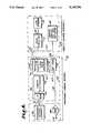
- FIG. 1is a block diagram of an image formatting system for recording, processing, and display of an image of spherical coverage which embodies the present invention.
- FIG. 2is a diagrammatic representation of the spherical field of view coverage provided within the system.
- FIG. 3is a diagrammatic representation of a video frame having image segments which comprise a composite image of spherical coverage.
- FIG. 4is a diagrammatic representation of a video frame having image segments which are arranged adjacently according to their true geographic adjacency.
- FIG. 5is a diagrammatic representation of a processed video frame shown in FIG. 4.
- FIG. 6is a block diagram illustrating a portable panoramic viewing and recording system (camcorder) with spherical field of view coverage.
- FIG. 7is a perspective view of a cameraman carrying the panoramic camcorder system of spherical coverage.
- FIG. 8is a perspective view of the panoramic camcorder system coupled with a remote control system.
- FIG. 9is a side elevational view with portions in section and showing the interior components of the panoramic camcorder system.
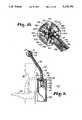
- FIG. 10is a greatly enlarged fragmentary sectional view of the optical assembly of the panoramic camcorder used for taking pictures of spherical coverage.
- FIG. 11is a greatly enlarged fragmentary sectional view of one of the optical assemblies of the camera and illustrates an optical assembly interface.
- FIG. 12is a greatly enlarged sectional view taken on line 12--12 of FIG. 11 and illustrates further details of the optical system.
- FIG. 13is a top sectional view of the remote control assembly showing the interior components thereof.
- FIG. 14is a cross sectional view taken on line 14--14 of FIG. 13 and illustrates further details of the remote control assembly.
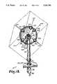
- FIG. 15is a perspective view of an alternative arrangement of the optical assembly of a panoramic camera with portions broken away to illustrate mirrors or prisms to reflect each image from the objective lens to a remote camera head.
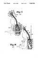
- FIG. 16is a side elevational view with portions broken away to show the interior of an alternative arrangement of the panoramic camcorder system which includes a transmitter for sending over-the-air video signals.
- FIG. 17is a view similar to FIG. 16 and shows a second alternative arrangement of the panoramic camcorder system which includes a plurality of camcorder systems with remote camera heads for recording a mosaic of picture elements constituting representing spherical coverage.
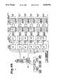
- FIG. 18is a block diagram showing details of the television production portion of the panoramic display system .
- FIG. 19is a block diagram of a graphics computer system for generating and rendering images for display in the panoramic display system.
- FIG. 20is a block diagram showing details of a video special effects unit incorporating a HMD assembly and floating viewpoint control panel to interactively define the scene viewed.
- FIG. 21is a block diagram showing details of a video special effects unit incorporating a video special effects unit including a position sensing system that is interfaced with the HMD to interactively define the scene viewed.
- FIG. 22is a block diagram showing a microcomputer based system for processing an image of spherical coverage for viewing in the HMD assembly.
- FIG. 23is a block diagram showing an alternative embodiment of a system for processing an image of spherical coverage.
- FIG. 24is a horizontal sectional view of a head mounted display (HMD) assembly and shows components of the HMD assembly.
- HMDhead mounted display
- FIG. 25is a sectional view taken on line 25--25 of FIG. 24 and illustrating further details of the HMD assembly.
- FIG. 26is a perspective view of the exterior of the HMD system worn by a viewer.
- FIG. 28is a diagrammatic representation of a video frame having a binocular coverage scene for viewing in a HMD display assembly and sampled from the frame in FIG. 3 which has adjacent field of view coverage image segments.
- FIG. 29is a diagrammatic representation of a video frame having image segments comprising overlapping stereoscopic spherical coverage for processing for display in a stereoscopic HMD assembly.
- FIG. 30is a diagrammatic representation of a video frame with a left and right eye stereoscopic view sampled from the frame in FIG. 29 for viewing in a stereoscopic HMD assembly.
- FIG. 32is a perspective, partially diagrammatic view showing details of an alternative arrangement of the image segment circuit means with a first and second image controller.
- FIG. 33is a block diagram showing details of an alternative arrangement of the image segment circuit means with plural input sources and image controllers.
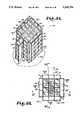
- FIG. 34is a perspective view of the exterior of a large image display assembly for displaying images of spherical coverage.
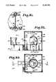
- FIG. 35is a top plan view of the display assembly enclosure with the ceiling removed to illustrate details of the assembly.
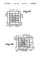
- FIG. 36is a cross sectional view of the display assembly enclosure taken on line 36--36 of FIG. 35 and illustrates details of the assembly.
- FIG. 37is a cross sectional view of the display assembly enclosure taken on line 37--37 of FIG. 35.
- FIG. 38is an enlarged fragmentary sectional view of a lower corner of the display assembly enclosure and illustrates details of the interconnection of the component sections of the display assembly.
- FIG. 39is an enlarged fragmentary sectional view of a top corner of the display assembly enclosure and illustrates details of the interconnection of the component sections of the display assembly.
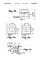
- FIG. 41is an enlarged fragmentary sectional view of an upper corner of the display assembly enclosure and fresnel lens plate assembly.
- FIG. 44is an enlarged fragmentary sectional view of a lower corner of the system enclosure illustrating details of the interconnection of the system enclosure and the fiber optic enlarging plate assembly.
- FIG. 45is a greatly enlarged fragmentary sectional view illustrating the positioning, supporting, and fastening of the fiber optic enlarging plate assembly.
- FIG. 46is an enlarged fragmentary sectional view of a lower corner of the display assembly enclosure illustrating details of the interconnection of the display assembly enclosure and a lenticular plate and rear projection screen assembly.
- FIG. 47is an enlarged fragmentary sectional view of an upper corner of the display assembly enclosure and the lenticular plate and rear projection screen assembly.
- FIG. 48is a greatly enlarged fragmentary sectional view illustrating the positioning, supporting, and fastening of the lenticular plate and rear projection screen assembly.
- FIG. 49is an enlarged fragmentary sectional view of a lower corner of the display assembly enclosure illustrating details of the interconnection of the display assembly enclosure and a rear projection screen assembly.
- FIG. 50is an enlarged fragmentary sectional view of an upper corner of the display assembly enclosure illustrating details of the interconnection of the assembly enclosure and projection screen assembly.
- FIG. 51is a greatly enlarged fragmentary sectional view illustrating the positioning, supporting, and fastening of the rear projection screen assembly.
- FIG. 52is a cross sectional view of a spherical projection assembly enclosure with a wall removed to illustrate details of the assembly.
- FIG. 53is a top plan view of a spherical projection assembly with the roof removed to illustrate details of the assembly.
- FIG. 55is a perspective, partially diagrammatic view illustrating the remote control viewing system described in FIG. 54.
- the reference 1generally designates a panoramic display system according to the present invention.
- the system 1generally includes an input means 2, signal processing means 3, and display means 4 connected generally by suitable electrical interface means 66. Electrical interface means 66 is indicated by lines and arrows in the drawings.
- Input means 2typically a panoramic video camera system 5 or graphics computer system 6, are provided such that image segments 13 of adjacent spherical coverage about a center point CP of a geographic or geometric system are recorded on a single frame 14 to form a composite image 26.
- Television signal processing means 3typically includes a television production unit 65 that switches incoming television signals to other signal processing components of the signal processing means.
- Componentsat least include a television special effects unit 7 for manipulation of an image prior to display; or image segment circuit means 8 for transmitting the processed television signal representing one of a plurality of image segments 13 or sub-segments comprising portions of a scene of a spherical field of view coverage to each predetermined illuminated image display unit 11 of the display means 4.
- the preferred embodiment of the system 1generally comprises two display means: a headmounted display (HMD) assembly 22 and a large display assembly 23.
- the HMD 22 and large display assembly 23are designed to essentially complement and emulate one another such that post production work is accomplished using the HMD assembly 22 which is more compact and economical to construct, while the large display assembly 23, which is less compact and more expensive to construct, is used by large audiences to view finished productions.
- the viewerwears the HMD assembly 22 to preview, manipulate, and review panoramic scenes recorded by input means 2 and manipulated by the signal processing means 3.
- a composite signal representing the composite image 26is transmitted to the image segment circuit means 8.
- the image segment circuit means 8performs operations on the signal representing the composite image 26 such that image segments 13 are transmitted to display units of the display assembly 23.
- the viewer's entire bodyis positioned in the large display assembly, referred to herein as a "VIDEOROOM" TM; in which the viewer is surrounded by display units such that the viewer sees a respective portion of the scene of spherical coverage in any viewable direction.
- the vieweris positioned at the center of a viewing space 25.
- the large display assembly 23is comprised of a structural framework 9 and supports 10, which hold the display units 11 and optical enlarging means 12 securely in place.
- FIG. 6illustrates the preferred input means 2 for recording a panoramic scene of spherical coverage, which is the panoramic camera system 5 including a camera 43, and which comprises a portable panoramic video viewing and recording system 27, referred to hereafter as a "panoramic camcorder".
- the panoramic camcorder 27is carried by a host being or vehicle.
- Housing means 28is provided to hold the major components of the camcorder 27 in place.
- the inner and outer portions of the housing 28are constructed of a conventional material, such as plastic or metal.
- Housing means 28includes a panoramic optical assembly 30 held in place by a optical assembly housing 31.
- the optical housing 31is supported over the camera operators head by a rigid support armature 33.
- the optical housing 31 and support armature 33are mounted to a the backpack housing 34.
- the backpack housing 34is held in place on the camera operator by straps 35 and fasteners 36 or other conventional means.
- Objective lenses 37a-37fare directed outward from a center point of the panoramic optical assembly 30.
- Each objective lens 37is preferably fixed and focused at infinity to cover a predetermined field of view.
- the optical assembly 30is associated with the panoramic video camera system 5.
- the optical assembly 30may be associated with still or movie photographic cameras (not shown).
- conventional objective lenses 37are incorporated which have wide angles of acceptance such that the image segments 13 have a wide field-of-view, but with minimal barrel distortion.
- a type of objective lens utilizedis generally of the type manufactured by Carl Zeiss of West Germany as the Distagon T*/f3.5 15 mm and the Distagon T*f/4 18 mm which have a circular field of view coverage of greater than 90 degrees.
- the optical assemblymay include a minimum of two "fisheye" objective lenses which cooperate to achieve a spherical field of view coverage.
- the fisheye lenseshave greater than 180 degree spherical field of view coverage and are faced in opposite directions on a similar axis at a short distance from a common center point.
- the fisheye objective lensmay be generally of the type manufactured by Nikkor Nikon of Japan, such as the 6 mm f2.8 fisheye lens with a 220 degree hemispherical field of view coverage.
- the objective lenses 37 and their associated focusing lensesare of a lightweight and compact design to facilitate integration with the optical assembly 30.
- Integral with the objective lenses 37a-37fare respective optical elements 63a-63f for transmitting the images in focus to the receiving end of each image fiber optic bundle 38a-38f.
- the objective lenses 37may be directed outward from a center point CP of the lens assembly 30 at any angle from the lens assembly housing 31 as long as the objective lenses 37 are arranged to achieve spherical coverage about the camcorder 27.
- the illustrated objective lenses 37a-37fare directed outward along right angle axes at 90 degree intervals of an x-y-z Cartesian coordinates.
- each objective lens 37transmits an image segment 13 with a field of view of 90 degree coverage across the optical axis OA. The result is that each image segment 13 is recorded in a square format with the center point of the square corresponding to the optical axis OAa-OAf of each objective lens 37.
- objective lens 37 atransmits scene 64a, lens 37b scene 64b, lens 37c scene 64c, lens 37d scene 64d, lens 37e scene 64e, and lens 37f scene 64f of the scene that surrounds the lens assembly.
- the scene of each objective lens 37a-37fis focused as an image segment 13a14 13f by the respective objective lens to the receiving end 39a-39f of a corresponding image fiber optic bundle 38a-38f.
- Each respective image segment 13a-13fis then transmitted by its respective image fiber bundle 38 to the exit end 40a-40f of the image fiber bundle 38, in focus and as a coherent image (See FIGS. 11 and 12).
- Conventional coherent image fiber optic bundles 38are incorporated in the optical assembly 30.
- the image fiber bundles 38may be of a rigid or flexible design, such that they can be bent at an angle to accept the image transmitted from the objective lenses 37, and then to bent at some point between the entrance end 39 and their exit end 40 to facilitate transmission of the image segments 13 to the receiving surface 42 of the camera 43.
- the optical fiber bundles 38are of a type that allows them to be twisted in route such that the desired image orientation at the exit end 40 of the bundle 38 is facilitated.
- the image fiber bundles 38have rectangular cross sections to facilitate the formatting of the image within the camera's format.
- image fiber bundles 38 of various cross sections and lengthsare commercially available for use within the present invention.
- a remote camera head 71FIG. 15
- very short fiber optic bundles 38be used to transmit the image from each objective lens 37 to the recording surface 42 of the camera 43.
- the image fibers that comprise the image fiber optic bundles 38are of a quality that allows low light transmission loss as the image is transmitted through the fibers.
- the optical elements 41are interfaced with the camera 43 to facilitate the composite image 26 being transmitted to the recording surface 42 of the camera 43 by conventional means, such as a screw or bayonet mount arrangement.
- the recording surface 42is directly associated with an image processor means 44 of a self-scanning solid state imaging device such as a charge coupled device located in the image plane of each respective lens element 41.
- a self-scanning solid state imaging devicesuch as a charge coupled device located in the image plane of each respective lens element 41.
- the lens elements 41may be omitted, and the exit ends of the fiber optic image bundles may be placed directly adjacent to or welded to the light sensitive recording surface 42 of the TV camera 43 to facilitate recording of the transmitted image segments 13.
- FIG. 3illustrates an exemplary picture frame 14 comprising a composite image 26 of spherical coverage recorded by the camcorder 27.
- Each image segment 13a-13fis placed on the frame adjacent to another image segment 13 to form a composite scene 26.
- FIG. 4illustrates an alternative frame format in which the exit ends 40 of image bundles 38 of rectangular and triangular cross sections are incorporated to form a composite image 26.
- the image segments 13are generally positioned on the planar surface similar to their geographic adjacency.
- Scene segments 64c and 64eare sub-segmented triangularly to facilitate conversion of a three dimensional scene to a scene where the image segments 13 have proper adjacency and orientation.
- objective lenses 37a-37f of camera 5 of FIG. 1are incorporated which have overlapping fields of view.
- at least two views of all scenesare recorded by the camcorder 27.
- a "fisheye" lenssimilar to that previously described, can be incorporated in the present invention to accomplish overlapping coverage (also see FIGS. 7-10 and 15-17).
- Objective lenses 37a-37f optical elements 63a-63f, optical elements 41a-41f, and construction of the optical housing 31, support armature 33, and camera interface means which may be utilized in the present inventionare manufactured for or manufacture by Schott Fiber Optics of Southbridge, MA.
- the camcorder 27also includes a conventional portable audio recording system commonly associated with conventional camcorder systems.
- the camcorder 27receives audible sounds for recording within proximity to the camcorder.
- each microphone 67a and 67bis integrated with the optical assembly housing 31 such that the microphones 67 face outward.
- the two microphones 67are dispersed respectively on the left and right side of the housing 31 such that stereo sound is recorded.
- Conductors 68are provided to transmit the audio signals from the microphones 67 through the support armature 33 to the recorder/player 47 where the audio signals are input using a conventional input jack.
- the microphones 67may be located elsewhere on the camera operator or elsewhere on the camcorder 27.
- the recorded audio signalsare synchronized with the picture being recorded by the camera 43 by means of the electronic circuitry of the recorder/player 47 such that a conventional television signal results.
- the electrical section 45is structured to convert the visual images received by the image processor 44 into electrical video signals such that the information is in a format that is compatible with standard video processing equipment. Any conventional TV camera 43 may be adapted to accept the images from the disclosed optical system 30.
- the image processor 44is structured to convert the visual images received into electrical video signals.
- the processed signalsare standard synchronized coded signals utilized in the United States for video transmission.
- the signal processor 3could be modified so as to convert the received electrical video signal from the image processor means 44 into a standard synchronized coded signal of any given country or format for transmission as desired, such as NTSC, PAL, SECAM or the like.
- the picture signal from the camera 43is then transferred through conductor 46 to a conventional portably structured videotape recorder/player 47.
- the conductor 46along with other conductors to be described hereinafter are positioned to be housed within a conductor sheath 61.
- An electronic interface generally indicated as 145is provided to receive the various signals being transferred over such conductors and to interface such signals for reception by and transmission from the video recorder/player 47 in any substantially conventional fashion.
- a connecting jack or suitable input connection, as at 146is provided for proper interconnection in a conventional fashion.
- a type of electronic interfacegenerally of a type utilized in the present invention, is referenced in U.S. Pat. No. 4,571,628. This television signal is then stored by the recorder/player 47 on video tape.
- the camera 43 and recorder 47, along with the lens assembly 31may be integrated into a single housing.
- Such an integrated housingis currently being marketed as conventional "camcorder" units.
- conventional camcorder componentsare incorporated to form the recorder and camera portions of the panoramic camcorder 27.
- U.S. Pat. No. 4,571,628 dated Feb. 18, 1986 to Thirstol Thortondiscloses components of a type which may form the components of the camcorder 27 of the present invention.
- Such conventional camcordersinclude integrated battery packs which supply electrical power to all components requiring electrical current to function.
- a conductor with suitable input/output jacksis provided for proper interconnection in a conventional fashion between the camera 43 and the recorder/player 47.
- the remote control assembly 62includes a remote control housing 29 including a wrist mounted video screen means 49 and remote controls 50 for operating the video recorder/player means 47.
- Conductor 60is interconnected from the video recorder/player 47 to the remote control housing 29 by conventional input/output jacks.
- the conductor 60 wiresare housed within a conductor sheath 61 and serves to transmit the recorded signal from the video recorder/player 47 to the video screen means 49 previously mentioned.
- the video screen means 49comprises a liquid crystal display drive circuitry 53 associated therewith and structured to electronically communicate with and receive the signal from the video tape recorder 47 through conductor 51.
- the liquid crystal display system 52may be of the type disclosed above and manufactured by Suwa Seikosha Co of Suwa, Japan.
- the size of the screen 49is such as to be capable of being mounted within a wrist mounted housing 29 wherein the display screen itself is approximately two inches in diagonal producing a substantially 43.2 by 32.4 millimeter display.
- the liquid crystal display means 52is specifically structured to convert the electrical video signal received from the video recorder 47 onto a visual display.
- FIGS. 13 and 14further structural features of the present invention include the provision of the remote control assembly 62 with individual activating controls or buttons 50 for appropriate switching (not shown) wherein the switching communicates with the video recorder/player 47 through conductor 60 also housed within conductor sheath 61 and interconnected to the recorder/player 47 through electronic interface 145.
- the individual activating buttons 50are structured to cause activation by switch conductors 60 so as to selectively activate the recorder in a play mode, rewind mode, record mode, and on/off switch as desired respectively, dependent on the function which the user wishes the mechanism to perform.
- the remote control housing 29is constructed of a rigid material such as metal or plastic. A conventional wrist band is provided to hold the remote control housing 29 to the camera operator's arm.
- an optical assembly 74 of the camcorder 27which is configured to provide an image of spherical coverage by incorporating reflective means 70 such as mirrors, prisms, or a combination of mirrors and prisms that transmit the image from the objective lenses through respective optical paths to the image processor 44 of the camera 43.
- Each objective lens 37a-37f including respective focusing lenses 63a-63fare located at approximately 90 degree intervals facing outward from a center point CP.
- the fields of coverage of the objective lenses 37a-37fare at least tangent or touching to achieve a spherical field of view or coverage.
- Each objective lens 37transmits the image in focus to the light sensitive recording surface 42 of the remote camera head 71.
- Planar mirrors or right-angled reflecting prisms 70are placed at 90 degree angles to the optical path such that the image is reflected to the light sensitive recording surface 42 of the remote camera head 71.
- Rotating dove prismsmay be provided and positioned incident to the optical axis along the optical path such that the incident image is rotated to the desired orientation within the optical assembly 74.
- Collective and erecting lens (not shown) elementsare provided to orient and focus the images as the images are transmitted along the optical path of the optical assembly 74.
- the optical componentsare held in place by a lens assembly housing 31 similar to that previously described.
- the housing 31contains the remote camera head 43 whose recording surface 42 is positioned perpendicular to the incident optical path of the transmitted images to facilitate recording of the incident images.
- the image transmitted by objective lens 37cis reflected directly onto the recording surface of the remote camera head, and requires no reflective means because lens 37a's optical axis is perpendicular and incident to the recording surface of the remote camera head.
- the remote camera head 71is positioned in the optical assembly housing 31.
- the connector cableruns from the remote camera head 71, through the support armature 33, and to the backpack housing 34.
- the remote camera head 71communicates a picture signal to the camera electronics by means of a connector cable 73.
- the cable 73is enclosed and supported by the support armature 33 which attaches to the backpack housing.
- the camera electronics unit and recorder/player 47are located in the backpack housing 34.
- the camera system with a remote camera head utilized aboveis generally of a type manufactured by Pulinx America Inc, Sunnyvale, CA as the TMC-50/TMC-60 RGB remote version.
- FIG. 16illustrates an alternative arrangement of the panoramic camcorder system 27 shown in FIGS. 6 in which an over-the-air transmitter 75 transmits a television signal representing a composite image of spherical coverage to a remote television receiver 76 (FIG. 1).
- the transmitter 75is of a compact portable configuration such that it is positioned in the backpack housing 34.
- the recorder/player 47outputs a conventional television signal over a conventional output cable 77 with conventional input/output jacks to the wireless over-the-air video camera signal transmitter 75.
- the transmitter 75transmits high quality over-the-air signals from a whip antenna 78 to the remotely located conventional television receiver 76 tuned into the proper channel and frequency.
- a portably configured video multiplexer(not shown) operates to combine the signals from each camera into a single recorder/player as a composite image.
- a video multiplexer system utilized aboveis generally of a type manufactured by Colorado Video Inc. of Boulder, Colorado as the 496A/B. The individual signals may then be demultiplexed for processing and/or display.
- a graphics computer 6is operated as an input source to create images comprising a spherical coverage.
- the computer system 6includes a digital computer 79 including a central processing unit, memory, communications ports, and the like.
- Operating system software, graphics software, processing data, generated images and the likeare stored in mass storage devices 80 which may include magnetic disk drives, optical disk drives, and so forth.
- Commands to operate the computer system 6 and graphics generation commandsare entered by means of the viewer interaction devices which may include a keyboard 81 and a graphics input device 82.
- the graphics input device 82may consist of one or more of a joystick, a trackball, a "mouse", a digitizer pad, or other such devices.
- the computer system 6includes a bit mapped video display generator 83 wherein each picture element or pixel is accessible for generating high resolution images.
- the video display generator 83is connected to one of the channels of the video production unit 65.
- the computer generated imagesare then further processed by the signal processing means 3 for display.
- the digital computer 79may be any type of computer system which has the required processing power and speed such as the type which are employed in computer graphic animation and paint applications.
- the computer system 6may function as a simulator controller if the display means of the present invention are used as simulators or as a game controller if the systems are employed as arcade games.
- the computer system 6may also be used to create special visual effects by combining artificial and animated scenes with live camera recorded scenes.
- an integrated part of the post production unit 65 and its video special effects unit 7is the graphics computer system 6.
- the graphics computer system 6is in direct communicating relationship with the special effects system 7 via the production unit 65.
- the keyboard 89, touch tablet 90, and host computer 91are also operated to control the processors and memory and other devices which comprise the graphics computer system 6.
- Various input sources 2may be routed by the production unit 65 to the graphics computer system 6 for rendering.
- the graphics computer system 6Once the graphics computer system 6 has been operated to create or affect an existing picture, the picture is stored in mass storage 80 or bused as a picture signal to the effects unit 7 or image segmentation circuitry means 8.
- Graphics system 6transmits a picture signal to the processor of the effects unit 7. In FIGS.
- a computer graphics system 6comprising a digital computer may be operated to create or effect the recorded video images.
- a system 6may be integrated with a television production unit 65 or special effects unit 7. The two are typically integrated in order for the viewer/operator to affect the video images captured by a camera. Typically the viewer/operator affects the video images frame by frame.
- Such a system 6is used in the present invention to affect the images captured by input sources.
- the components in a typical vector or raster electronic graphic system 6include a touch tablet 90, a computer 91, framestore 86, and a display.
- a graphics computer system of a type utilized hereinis generally of the type manufactured by USA Quantel Inc., Stamford, CT as the Quantel Graphics "Paintbox" TM.
- each frameconsists of a composite image representing a scene of spherical coverage.
- the signal processing means 3performs two major signal processing functions in the preferred system: first, the video post production unit 65 that includes a TV special effects unit 7 is used to compose the image for viewing; and second, image segment circuit means 8 distributes the scene of spherical coverage to the display means 4 for viewing.
- FIG. 18illustrates a video production unit 65 for viewing, composing, and distribution of television signals representing a panoramic scene of spherical coverage.
- the video production unit 65is comprised of various image processing devices.
- a panoramic camera system 5inputs a standard television signal on which the image has been encoded as a composite image 26 of spherical coverage for application to the television production unit 65.
- a plurality of image segments 13 from a plurality of cameras 72may be input to the production unit 65.
- the production unit 65may have compression functions, the ability to create multiple split images, and the ability to position the split images at selected locations on a video screen.
- the unit 65includes image compression controls 157 for accomplishing such functions.
- the production unit 65preferably includes a subset monitor bank 155 including a video monitor corresponding to each video camera.
- a composite image monitor 156 connected to the production unit 65allows viewing the image segments 13 assembled onto a single screen.
- the assembled images 26, as processed by the production unit 65 and viewed on the composite image monitor 156,may be stored.
- the production unit 65is of a conventional type (see FIG. 18) that also has audio and video switching and distribution functions such that a single or a plurality of channels can be input and output to the television special effects units 7, the segment circuit means 8, the graphic computer system 6, or the display 11 and recording 153, 154 units.
- the unit 65includes video switching controls -58 and audio switching controls 159 for accomplishing such functions.
- a production unit 65 of the type generally utilized in the present inventionis manufactured by Industrial Sciences, Inc.
- An image compression unit of the type generally utilized in the present inventionis manufactured by Precision Echo, of CA, as the "Squeezer”.
- some input meanscan transmit a signal representing a composite image 26 directly to the TV special effects unit 7 and then to an associated HMD assembly 22.
- An input meanscan also transmit a signal representing a composite image 26 directly to the segment circuit means 8 and then directly to an associated large display assembly 23.
- the TV production unit 65is not necessary to connect components of the system to facilitate post production work as shown in preferred arrangement of the system 1 shown in FIG. 1.
- the composite signalis applied by the television production unit 65 to an analog-to-digital (ADC) converter 84 whose digital output is transmitted to the television special effects unit 7.
- ADCanalog-to-digital
- the effects unit 7such as that described in U.S. Pat. No. 4,563,703 and U.S. Pat. No. 4,334,245, is used to manipulate the image segments 13.
- the component signals comprising image segments 13a-13fare transmitted from the panoramic camcorder 27.
- the image segments 13are manipulated by the effects unit 7 to generate the effect to the viewer that he or she can visually pan the scene of spherical coverage.
- the effects unit 7performs programmed mathematical operations on the input composite scene resulting in the reconstruction of the image segments 13 specified for viewing.
- the image segments 13are reconstructed in the same geographic or geometric orientation in which they were recorded.
- the effects unit 7receives a standard television signal representing a composite image 26.
- the signaltogether with information previously stored in framestore 86, is operated upon within the effects unit 7.
- the x, y, address which is used to access the framestore 86 at a given picture point locationis determined by the output of an address mechanism 87.
- a parameter Zis provided by the address mechanism for controlling the processing within the processor 88.
- a keyboard 89 or a touch tablet 90is used to input standard mathematical formulas to generate the desired polyhedral shapes (such as a cube shown in FIG. 2a) in the computer 91. Other shapes, such as a sphere could also be input.
- disc 92contains a whole range of shapes including shape sequences to allow picture transformation from one shape to another to be achieved. Once the shapes have been entered, the computer 91 is not necessarily required thereafter, and the system merely uses the disc store 92 as its shape data source. The disc access is generally not rapid enough to accommodate near real-time video rates of addressing.
- an address interpolator 93is used. The disc store 92 holds coarse cell address data used to address specific cell patches within a recorded picture frame of matrixed pixel data. The interpolator 93 addresses every 8th frame.
- address mechanism B7produces the main x, y, address for the respective framestores 86, the fractional (Z) part of the address, and the density compensation value (K).
- address mechanism 87addresses framestore 86 and video processor 88 cooperate to wed every eighth live or prerecorded video frame with a shape. The wedding of shape and content is called texture or surface mapping.
- the video processing system 7may form the cube by wrapping, warping, twisting, or moving the video.
- FIG. 3shows a typical video frame 26 comprised of six image segments 13a-13f representing portions of the surrounding scene of spherical coverage. Portions of the picture 13a-13f are moved and wed to the sides of the cube defined in the video processing system 7. More specifically, the type of special effects unit 7 utilized are generally of the type manufactured by Quantel Inc., of Stamford, Conn., as the "Mirage” TM; as part of their video "Digital Production Center”.
- FIG. 4shows a video frame 14 recorded by the panoramic camera 27 in which 13a-13f may be folded or wrapped into a cube.
- the effects system 7 or video graphics board 171mazy achieve a wrap-around effect without using a 3-dimensional mathematical formula (also see FIGS. 18, and 20-22).
- the vieweroperates the effects system 7 or computer 171 to pan a 360 degree scene on the horizontal axis.
- An arrow(FIG. 4) is oriented in the direction of the pan.
- Image segments 13, representing adjacent portions of the sceneare placed in side-by-side touching or tangent relation.
- FIG. 5illustrates a wrap-effect command operated upon by the image processing system 7 or 171 such that when a write command goes to the maximum limits of the x or y coordinates of the buffer, the coordinates automatically re-enter the buffer again on the opposite edge.
- the image processing system 7 or 171automatically performs calculations such that the opposite edge 48a2 of image segment 64d is automatically placed tangent to edge 48a1. In this manner a viewer can achieve a wrap around effect which provides the visual effect of being able to pan a scene of spherical coverage.
- FIG. 20shows a simplified arrangement of the system where the viewer/operator uses his hands to operate a floating viewpoint control panel 94 of address mechanism 93 to interactively define the portion of the scene he or she wishes to view.
- Panel 94is used in lieu of the keyboard 89 or touch tablet 90 for input into computer 91.
- a panel 94 of the type generally utilizedis manufactured by Quantel Inc., Stamford, CT, as the "Floating Viewpoint Control Panel" TM.
- the control panel 94has a track ball (not shown) for controlling the x, y viewpoint parameters, and a shift bar (not shown) for controlling the z viewpoint parameter of the created shape.
- the viewerhaving previously defined a cubical shape and K so that the viewpoint appears to be at CP as shown in FIG. 2, operates the shift bar and tracker ball to pan the inside walls of the cube on which image segments 64a-64f are texture mapped as a continuous scene.
- the address interpolator 93 of address mechanism 87responds to the spatial address interpolator 93 for interpolating picture point addresses in pictures intermediate of two separated pictures.
- the multipliers and adders of the system 7define the picture to be viewed based on the x, y, z orientation of the cube.
- the value of compression K, length L, and time Twill vary between 0 and 1 typically in 1/8 steps as the addresses to modify the successive shapes within each frame are calculated. This allows any change in address shape between the 8 frame periods to be gradually introduced.
- Effects system 7can be programmed to warp image segments of the composite picture. This type of operation is conducted to remove barrel distortion introduced by wide angle objective taking lenses, such as "fisheye” lenses, that may be used with the panoramic camera system 27.
- wide angle objective taking lensessuch as "fisheye” lenses
- the signal representing the processed imageis then typically reconverted into an analog form by digital to analog converter (DAC) 85.
- DACdigital to analog converter
- the converters 84 and 85are standard items used in digital video systems and are therefore not described further.
- the digital signalis typically converted to standard NTSC synchronized analog signal compatible for input with the head-mounted display assembly 22 or the image segment circuit means 8.
- FIG. 21shows a more complex embodiment of the system in which a position sensing system 95 mounted on a head-mounted display assembly 22 worn by the viewer/operator VO 32 defines the resultant scene viewed.
- FIGS. 24 through 26illustrate the construction of the head-mounted assembly 22 to be described hereafter.
- the viewer/operator VOwears the head-mounted display assembly 22.
- the head assemblyincludes a helmet 96 constructed of a non-metallic substance, preferably plastic, which does not interfere with the electronics of the position sensor 97.
- Mounted on helmet 96is a position sensor 97 which monitors the magnetic field generated by a magnetic source 98.
- the sensor 97is a lightweight cube whose position and orientation is measured as it moves through free space.
- the source 98generates a low-frequency magnetic field for pick-up by the sensor, and is the reference point for sensor measurements.
- the source 98 and the sensor 97both receive an analog voltage signal.
- a voltage signal transmitted to the sensoris pulsed burst, and energizes x, y, and z coils (not shown) in turn or in phases.
- the affected current for each coilis then transmitted from the sensor to the position sensing system electronics unit 99.
- Each coilprovides three readings for a total of nine readings that are processed in the position sensing system electronics unit 99 to provide position and orientation data readings.
- the source 98is stationed in relation to the viewer/operator in a stationary location several feet from the viewer/operator.
- the position sensor 97transmits electronic signals providing position (x-y-z coordinates) and orientation (angular vectors), with respect to the location of source 98, to the position system electronics unit 99.
- System electronics unit 99contains the hardware and software necessary to control the tracker elements and interface with the host computer 91 or address mechanism 93 of the video effects system 7.
- the signal transmitted from the system electronics unit 99 to the host computer 91is a digital signal.
- Computer 99 or address mechanism 93is connected through a serial output port on the system electronics unit 99.
- a system electronic board in the form of a printed circuit board 100which has the same capabilities of unit 99 and occupies an separate console, may be plugged into the host computer terminal bus. If the board 100 is used, the source 98 and sensor 97 transmit position sensing data to the board 100. Conductor links from the board 100 provide electrical current to the source 98 and sensor 97.
- Position sensing systems 95 and 100 of a type generally utilizedare manufactured by Polhemus Navigational Sciences Division of McDonnell Douglas Electronics Company, Colchester, VT under the name "3SPACE Isotrak" TM.
- the updated coordinatescause the multipliers and adders of the video effects unit 7 to update the field of view every 8 frames and in 1/8 steps, conveniently using a look up table.
- the effects system 7is configured to be frame addressable and pixel addressable. As illustrated in FIG. 2, the pixels of each image segment 13 of each composite image 26 are associated with cartesian coordinates of a three dimensional scene of spherical coverage about a substantially common viewpoint. As shown in FIG. 3, once the scene is translated onto a planar frame format, each three dimensional coordinate pixel point is addressable as a corresponding x-y axis pixel point.
- Look up tablesare programmed into the effects system 7 to mathematically define the relationship between the three dimensional world and the two dimensional world represented.
- the look up tablesare operated upon by the effects system 7 to facilitate a three dimensional effect on the two dimensional display means provided in the HMD assembly 22.
- the position sensing system 95affects the video effects unit 7 such that the portion of the panoramic scene displayed on the HMD display assembly 22 corresponds to the upward head movement of the viewer. In this way the viewer can interactively scan the entire simulated scene of spherical coverage.
- adjacent objective lenses 37a-37f of the panoramic camera system 5have adjacent overlapping coverage such that at least two views of all portions of the surrounding scene are recorded, and a stereographic image may be sampled by the image processor 7 for stereographic viewing.
- each objective lens 37a-37fmay consist of a fisheye lens with greater than 180 degree field of view coverage.
- FIG. 29illustrates a composite image 26 whose image segments 13a-13f each have greater than 180 degree coverage.
- the image processing system 7performs mathematical operations using look up tables to define corresponding left eye and right eye views to be sampled from the composite image 26 based upon the point of view defined by the viewer.
- a stereographic field of viewis arrived at by sampling left and right eye fields of either side of the orientation defined by the position sensors 97.
- image segments 13 for the left eye and right eyeare chosen from two adjacent objective lenses 37, each with a different, but adjacent, overlapping field of view of the visual scene.
- the point of viewis defined automatically by the position sensing system 95 associated with the HMD assembly 22.
- FIG. 30illustrates the resultant stereoscopic image 101 that the image processing system 7 has processed for stereographic display.
- a single stereographic image 101represented on a single frame and output over a single channel to a single display, may be viewed on the HMD assembly 22 in FIGS. 24 through 26.
- the stereoscopic image 101may comprise a single frame and be transmitted over a single channel to the display means 4, or may be segmented for display on two channels.
- image segment circuit means 8such as a type described later, may be provided to segment the stereoscopic image 101 into a left eye and right eye image each for distribution over two separate channels.
- the segment circuit means 8may be operated to scan out the same scene, adjacent scenes, or overlapping scenes from a binocular or stereoscopic frame created by the special effects unit 7. Each channel's signal is then applied to a display associated with the correct eye.
- the HMD assembly 22 with two display units of a type generally utilized for stereoscopic viewing with two channels hereinis manufactured by VPL Research Inc., Redwood City, Calif., as the "EyePhone" TM System.
- FIG. 22illustrates an alternative arrangement of system 1 in which the signal processing means 3 for the HMD assembly 22 comprises a microcomputer system 165.
- the systemincludes a digital computer including a central processing unit 165, terminal bus 168, communication ports 177, memory, and the like.
- Operating system software, board level software, processing data, generated images and the likeare stored in mass storage devices 80 which may include disk drives, optical disk drives, and so forth.
- a conventional microcomputer generally of a type utilizedis manufactured by International Business Machines of Armonk, New York as the 386 based "IBM PC AT" (TM).
- the microcomputer 165includes expansion slots for adding circuit boards on the bus 168. The boards are addressed over the system bus 168 of the microcomputer 165.
- Commands to operate the computer system 165 and associated board level commandsare entered by means of the viewer interaction devices which may include a keyboard 81, and printed circuit board level systems such as position sensing system 97, 98, and 100, videographics system 171, and a voice recognition system 169 and 170.
- the operation of the board level position sensing system 100is similar to the position sensing electronics unit 99 and associated components described earlier.
- the position sensing board 100transmits position and orientation data to the videographics board 171 to define the scene viewed in the HMD assembly 22.
- the videographics board 171operates to pan, zoom, and wrap each composite frame shown in FIG. 4 in a manner previously described according to FIG. 5.
- FIG. 23illustrates a modification according to the present invention of a system shown in U.S. Pat. No. 4,463,380, in which a system of hemispherical coverage is modified for processing a spherical image. Illustrated is the image processing system 7 wherein information corresponding to a selected spherical geographical region or geometric system is stored and selectively retrieved and processed to reproduce images corresponding to selected portions of the spherical geographical or geometric system. In a preferred embodiment, the information is initially recorded photographically and subsequently stored in a digital recording system. Processing, memory, and control systems are employed for producing video signals to be provided to video display units, for producing simulated real time images corresponding to the selected portion of the geographical or geometric system.
- a panoramic camera system 6 of overlapping spherical coveragereplaces the hemispherical camera of U.S. Pat. No. 4,463,380.
- the processing system 3is reprogrammed to accept and process images of spherical coverage.
- Display assembly means 4, as described herein,are provided to display the processed image of spherical coverage.
- Image segment circuit means 8are provided to distribute the images comprising spherical coverage to the large display assembly 23.
- the function of the digital processing circuitry means 8is to accept an incoming NTSC television signal and to display it over an array of display units 11 so that the resulting image appears as it would on a single very large screen TV that completely and continuously surrounds the viewer. This is called segmenting an image.
- the circuit segment means 8generally includes:
- an input signal representing a composite scene according to frame 26 of FIG. 3 is transmittedis from an input means 2, such as a panoramic video camera 5, to the video distribution switcher/amplifier 116.
- an input means 2such as a panoramic video camera 5
- the video distribution switcher/amplifier 116Such a video distributor is manufactured by Delcom USA, Inc., Philadelphia, Pa., for use in their "VIDEOWALL" TM systems.
- Video distribution amplifier/switcher devicesare well known to those in the industry and so will not be described in detail.
- An image processing system or video image controller 117, described hereinafter,can alternatively be operated to distribute a signal representing the composite image 26, image segments 13a-13f, or sub-segments 13a1-13f12.
- the distributor 116routes the input video signal representing a composite image to a plurality of control units or red-green-blue (RGB) converters 178a-178f.
- RGBred-green-blue
- Each RGB converter 178converts the signal into RGB signals and routes them to a respective image controller 117a-117f.
- the image controller manufactured by Video Matrix Corporationmay be incorporated in which an NTSC signal may be routed directly to the image controller 117 which accomplishes the RGB conversion internally.
- the electronic video controller system 117a-117faccepts the incoming video signal and partitions and processes it for display on the display units 11a1 through 11f12.
- the imageis partitioned into "segments", one segment or sub-segment for each display unit 11.
- the edges of the segments 13a-13fare denoted by dashed lines, and the edges of the sub-segments 13a-f,1-12 are denoted by dotted lines.
- the image controller 117is capable of accepting a single NTSC type video signal and dividing this single image into a displayable array covering 2 ⁇ 2, 3 ⁇ 3 or 4 ⁇ 4 television units.
- the segment on any individual display unitmay be frozen, independent of the incoming signal, and the system is compatible with certain computer generated graphic images.
- the number of vertical and horizontal picture elementsIn order to cover the 2 ⁇ 2, 3 ⁇ 3 and 4 ⁇ 4 monitor array configurations while maintaining a reasonably clean system design, it is desirable to set the number of vertical and horizontal picture elements to a value which is divisible by the least common multiple of the array size, in this case 12.
- the number of vertical lines in a standard TV frameis 480, which meets the above criterion.
- the number of pixels to be sampled in each horizontal lineis somewhat arbitrary; a larger number provides better resolution at the cost of increased processing speed.
- a number which meets the above criterion and which is reasonable from both the resolution and processing standpointsis 768 pixels per line.
- the 768 pixel per line sampleis about (14.318 Mhz), which is 4 times the color subcarrier frequency exceeding the Nyquist Sampling Criterion by a fairly comfortable factor of two.
- the active portion of a video line of informationis displayed in an interval of about 54 microseconds. Given a sampling of 14.31313 Mhz, 773 video samples can be acquired in this time of 54 microseconds.
- the systempreferably allows for selection of image storage elements within the image memory with boundaries identical to those associated with 2 ⁇ 2, 3 ⁇ 3 and 4 ⁇ 4 display unit arrays.
- each display unit output channelmay be provided with an individual sub-frame of storage.
- the incoming NTSC signalprovides a complete video image typically each 1/30th of a second.
- the system 117produces N (4,9,16 . . .) processed image segments and N' sub-segments (e.g. 48,108,192 . . .) in the same 1/30th of a second. Each segment contains the same number of lines as the original image.
- the process for performing this type of functionis known as "scan conversion and interpolation".
- Scan conversionis the production of information at a rate different form that at which it is acquired.
- Interpolationis the provision of a finer grain in the information output than is present in the input. This general technique of scan conversion and interpolation is used in acquisition and display systems for medical imaging and military imaging applications.
- System 117typically consists of four discrete modules when the image converters 178 are not present: an NTSC converter and digitizer; a frame memory; a line segment router; and output converters (not shown).
- the NTSC converter and digitizer 178converts the incoming NTSC video signal to a stripped, DC restored video and sync form. It digitizes the video signal in time synchronization with the stripped sync signal and passes the resulting image data to the frame memory.
- the datais stored in frame memory of controller 117 (a digital storage system, preferably a high-speed solid-state memory) as sequential image lines taking into account the interlaced nature of the NTSC signal.
- the frame memoryacts as a data storage device for a full frame of video data, consisting of two interlaced fields each containing 240 lines of information.
- the line segment routerextracts segments of video lines from frame memory and routes these line segments, appropriately, to a number of output converters, one of which is associated with each video display unit displaying some portion of the desired image.
- the output converterstake the line data and perform the necessary interpolation and digital-to-analog functions to produce an RS-170 (RGB+SYNC) video signal to drive the individual TV display units 11.
- the line segment router and the output converterare programmable to accommodate the multiplicity of display unit array sizes. In this way image segments and sub-segments can be scanned out of the composite image signal.
- Video imagesare conventionally generated in an interlaced fashion wherein every other line in the image frame is generated during one field interval the alternative lines are generated during the next field interval. If each frame of video information is written to a memory and read out, for example, onto a 2 ⁇ 2 array of monitors, with the writing and reading process beginning at the top of each image and proceeding to the bottom of the image, the writing process will overtake the reading process almost immediately on the top row of monitors and again 3/4 the way down the image (in the center of the bottom row of display units). The implications are that the information contributing to the 1/4 of the image beginning at the top of the lower row of units will be out of time sync with the remainder of the image by as much as 1 frame interval, depending on motion, which is clearly unacceptable.
- each image controller 117a-117fis a central processing unit (CPU) 120a-120f, respectively, which executes software commands to effect the processing of the images in each framestore memory of framestore cards 121a-121f.
- the CPU's of each image controllerare connected by an internal bus to each respective framestore card.
- the software commands read by the CPUmay be pre-recorded onto optical disk, video tape, or image controller by use of a conventional microcomputer 122.
- the viewer operatormay interactively operate a conventional microcomputer 122 programmed to interact with segment circuitry means 117 by operating an input device 123, such as a keyboard.
- the microcomputer 122is connected by a control bus to the image controllers 117a-117f via the distributor 116.
- the microcomputertransmits software commands to the image controllers 117a-117f to effect image display.
- Software commandsconsist of time code and program code for control of the displayed picture.
- the host computer 122is also used to input software commands that specify the picture aspect ratio to be scanned for display.
- the signal representing the composite image within the image controller 117may be segmented into image segments 13a-13f or sub-segments 13a1-13f12.
- the video signal representing each framestore cards (not shown) picture segmentis then transmitted to a corresponding display unit 11.
- the number of picture segments that the image controller can segment the composite picture intovaries and determines the maximum number of display units that can be accommodated.
- image segmentsare pre-formatted by the panoramic camera 5 to correspond to the picture segmentation accomplished by the image controller 117.
- the associated audio signal transmitted from the input sourceis applied to an audio distribution system 126.
- the audio signal 129is applied to an amplifier 127 which transmits the signal to audio speakers 128.
- Image segment circuit means 8including an audio system, of the type generally utilized in FIG. 31 of the system 1 is marketed by DELCOM USA, Philadelphia, Pa. and includes image controllers 117 sold as the "Station Pro” and "Universal”.
- any image processing system 3that facilitates the segmentation and distribution of images of spherical coverage can be adapted for use within the present system.
- Similar segment circuit means 8which is of a type generally utilizable within the scope of the present invention is also disclosed in U.S. Pat. No. 4,734,779.
- FIG. 32illustrates an alternative segment circuit means 8 arrangement in which a first image controller 117 transmits an image segment 13a-13f of the composite image to a second image controller.
- the second image controller 117a-117foperates upon the transmitted signal to sub-segment the image.
- the sub-segmented imageis then applied to an associated display units 11a-11f,1-12.
- the first and second image controllersreceive program and time code in the form of computer language over a control bus from the programming computer 122 as previously discussed. Dots in FIG. 3 indicate the edges of the sub-segmented image 131a1- 13f12 displayed on the display units of FIGS. 31 through 33.
- Image segment circuit means 8 of the type generally utilized in FIGS. 31 and 32 of the system 1is manufactured by DELCOM USA, Inc., Philadelphia, Pa., and includes a first image controller and a second image controller sold under the name Universal and Station Pro respectively.
- FIG. 33illustrates a segment circuit means 8 arrangement in which a plurality of image controllers 117a-f receive an image segment 13a-13f from a respective input source 2.
- Each block of display units 11a-11f, 1-12receives an image sub-segment from an associated image controller 117a-117f.
- a microcomputer 122is programmed and operated to control the functions of each image controller 117a-117f and input source 2.
- Image segmentation circuitry means 8 of the type generally utilized in FIGS. 33 of the system 1is manufactured by North American Philips Inc., of New York, N.Y. under the name "VIDIWALL".
- FIG. 23illustrates an additional arrangement for image segment circuit means 8 which is adaptable and of a type which may be utilized in system 1 and which is manufactured by Vought Corporation, Dallas, Tex., and described in U.S. Pat. No. 4,463,380.
- Segment circuit means 8may be configured to sample out an image segment or segments for display in the head mounted display assembly 22 or numerous image segments for large display assembly 23.
- the video effects unit 7cooperates with the head-mounted display assembly 22 which is designed to allow the viewer a natural field of view.
- a humans binocular visual fieldis about 130 degrees vertically and 208 degrees horizontally, assuming the eyes to be fixated straight ahead.
- the vertical fieldextends from 60 degrees above horizontal to 70 degrees below.
- the horizontal fieldextends 104 degrees laterally (left and right). With an overlap at the center point of the viewed image of about 30 degrees for both the left and right eye.
- the field of viewis a function of compression (K) as defined by the viewer/operator of the effects system 7.
- the digital-to-analog converter 85transmits the video signal to the head mounted display means 104 of the HMD assembly 22.
- Head-mounted display means 104consist of a conventional portable flat television display 105 generally of a type manufactured by Sony Corporation, Tokyo, Japan as US Model FD-40A, U.S. Pat. No. 4,339,694 or by Casio Computer LTD, Tokyo, Japan, under U.S. Pat. No. 4,562,478.
- the portable television 105receives a conventional television signal.
- the signal output by the effects unit 7is processed to be compatible for input to the television unit.
- the signalmay be transmitted to the TV over a conductor and input through a video input jack or broadcast over-the-air to the portable television.
- a portable televisionhas a audio/video input jack for receiving a standard video signal.
- Portable television 105is held in place by conventional fasteners and is a sub-assembly of the HMD assembly 22.
- the display means 104 portion of the portable television 105is positioned flush or immediately adjacent to dispersion lens means 106.
- the placement of the dispersion lens means 106allows projection of the displayed image on display means 104 in visual communication via lines of sight 107 and 108 with the respective right eye (Er) and left eye (El) of the viewer.
- the displayed image on display means 104is reflected to reflector elements or mirrors 109 through viewing lens 111 to the viewers right eye Er.
- the displayed image on display means 104is reflected to reflector elements or mirrors 110 through viewing lens 112 to the viewers left eye El.
- Mirrorsare mounted such that they are adjustable to achieve overlapping or non-overlapping coverage.
- the mirrorsare mounted in brackets 147 and 148 that may be slid forward and backward to define the portion of the displayed scene reflected from the display means to the viewers eyes.
- Position sensor 97is mounted at the rear of the helmet.
- the position sensor 97is connected to the position electronics unit 99 by a conductor and appropriate interface means.
- the audio reception from portable television 105is transferred to the viewers ears using conventional headphones which plug into the earphone jack 114.
- Earphones 115a and 115bare provided for both the left and right ear, respectively.
- the helmetis of a lightweight material, such as plastic that holds the components of the assembly in place. Cushions are placed in the helmet to facilitate the wearing of the helmet by the viewer.
- a large display assembly 23is provided to receive and display the image of spherical coverage to large audiences once post production work using the HMD assembly 22 has been completed.
- the large display assembly 23is configured in a polyhedral arrangement.
- the display assemblycomprises a structural assembly that enclosed the viewers head, upper body, or entire body.
- the assemblyis designed to facilitate a single or plural number of viewers.
- the floor 130 and its associated display units 11 beneath, to the sides, andover the viewer/operatorare integrated so the viewer is presented with a substantially continuous scene for viewing.
- the structural framework 8, supports 10, and associated fasteners 134are integrated with the display assembly such that they are hidden from the viewer.
- structural framework 9 and supports 10are constructed of conventional metal rods and plates, respectively. The structural supports 10 and framework 9 cooperate to securely hold the display systems 11 and optical enlargement panels 12 securely in place.
- the floor 130 on which the viewer is situatedis preferably of a rigid transparent material through which the viewer sees the viewing side of the display systems or optical enlarging assemblies.
- the viewing side of the display systems or optical enlarging assembliesis constructed of materials that support the viewer.
- the material on which the viewer is situatedis preferably formed of a transparent rigid glass, plastic, or glass-plastic laminate.
- FIGS. 23 and 31-33illustrate how the processing means typically relates to the display assembly.
- each framestore card, 121a1-121a12, 121b1-121b12, through 121f1-121f12 associated with image controllers 117a-117f respectivelyoutput a picture signal representing sub-segments 13a-13f,1-12 of the composite image 26.
- Each respective display units electrical circuitrypossesses the signal for display.
- Conventional display unitssuch as flat panel 17, cathode ray tube (CRT) 16, or video or laser projector 15 units are incorporated to receive the image segments from each image controller 117a-117f.
- FIGS. 35 through 39illustrate a basic display assembly 23 that uses CRT's 16.
- FIGS. 49 through 53illustrates a similar assignment that incorporates projector units 15.
- the example presented in FIGS. 35 through 37uses seventy-two display units 11, comprised of six arrays of twelve display units each.
- FIGS. 52 and 53illustrates a system in which a single display unit 11a-11f is positioned to each side of the viewer to achieve a scene of spherical coverage.
- a single image controller using six framestore cardstransmit image segments to a corresponding number of display units.
- Displays of various aspect ratios and color or monochrome displayscan be incorporated.
- Display subsystemsare located to the rear of the display units such that the viewing surface of the display unit is maximized and the frame of the display unit minimized.
- Display unit control and adjustment leversare located on a small area on the front of the panel, located on the back side of the panel, or preferably, located in a console in an adjacent room. Each display is powered by standard power source using conventional electrical outlets.
- FIG. 38shows an enlargement of the bottom corner of the large display assembly 23 shown in FIGS. 35 through 37.
- Floor framework 9eholds the display unit supports 10e of the floor above the stage 133.
- the display unit supports 10ehold the transparent flooring material 130 above the display units.
- the transparent flooring material 130in turn supports the viewer and any associated interactive input, control, or peripheral systems located in the viewing space 25. The viewer observes the display units 11 below him through the transparent flooring material 130.
- Access space behind the display screen of the display unitsis allowed for ventilation, electrical cables, and wires, audio speakers required to operate the system. Display units are packed beside one another as tightly as possible to increase the continuity of the displayed panoramic scene.
- FIG. 39shows an enlargement of the top corner of the assembly 23 shown in FIGS. 35 through 37.
- Display units over the viewer that form the ceilingare held securely by ceiling display unit supports 10c which surround and are fastened by fasteners 134 to each display unit 11c.
- the display support framework supports 10care fastened by conventional fasteners 134, such as nuts and bolts or welds, to horizontal beams 9c of the supporting structural framework 9.
- the horizontal beamsform a matrix that is supported by vertical columns of the framework 9a, 9b, 9f, and 9d.
- the vertical columns 135are supported by the stage 133.
- the vertical columns 9a, 9b, 9f, and 9d of the assembly 23hold the CRT display unit supports 10a, 10b, 10f, and 10d which form the wells of display units 11a1-12, 11b1-12, 11f1-12, and 11d1-12 located to the sides of the viewer. Access space for electrical cables, ventilation ducts, and audio speakers are positioned behind the display units 11.
- optical enlargement means 12hide or minimize the undisplayed area between and around the active viewing portion of each display unit so that a viewer sees a continuous scene in any viewable direction.
- Enlargement means 12comprise a plurality of optical enlargement plates 19, 20, 21 or screens 18 arranged adjacent to one another to form an assembly. The edges of the adjacent enlarging plates or screens may be constructed to be overlapping and/or interlocking. The optical enlargement plates or screens are placed between the display units and the viewer. Optical enlargement plates or screens can be constructed to have either curved or flat sides facing the viewer.
- FIG. 40floor 130 and display unit support 10e support fresnel lens plates 20e, a thin transparent protective floor cover 135 is positioned on top of fresnel lens.
- the floor cover 135protects each fresnel lens plate below the viewer from damage by the viewer who is situated upon the floor.
- FIG. 42shows an enlarged detail in which fresnel lenses on the wall and ceiling are supported at the edges by fresnel lens support armatures 132. Armatures 132 are fastened by conventional means to each corresponding display units supports 10 at one end and to an associated fresnel lens plate 20 at the other end.
- Each support armature 132is angled toward the viewer so as to not interfere with reflected light cast from the viewing side of the display unit 11 to its corresponding fresnel lens plate 20.
- each fresnel lens 20is positioned parallel to a corresponding display unit 11 viewing surface.
- Each display unit 11reflects image through an associated fresnel lens plate 20 to the viewer.
- the edges of each fresnel lens plate 20is positioned tangent to an adjacent fresnel lens plate 20 and appear to reflect a continuous scene about the viewer.
- the floor support, fresnel lens plates, and protective floor coverare constructed of any suitable transparent material such as plastic or glass.
- Fresnel lens platesare optically formed so that they cooperate to reflect a continuous scene to the viewer.
- Fresnel lens plates of a type generally utilized in the present inventionare manufactured by North American Philips Inc. for use in their "VIDIWALL" TM system.
- FIGS. 43 through 45illustrates another arrangement of the enlarging assembly.
- FIG. 44illustrates an enlarged view of a top corner of the assembly 23 shown in FIGS. 21 through 25 which incorporates fiber optic plates 21, to surround the viewer such that a continuous uninterrupted scene is displayed to the viewer. Edges on the viewing side of each plate 21 are placed tangent to one another.
- a plurality of adjacent fiber optic image transmitting guides 139reflect adjacent portions of the displayed image of the displayed image of the display unit 11 to the viewing side 137 of the fiber optic plates in focus.
- the fiber optic guides 137are tapered and increase in width as they go from the receiving side 138 to the viewing side 137 of fiber optic plate 21.
- the main body of the fiber optic guides 139tilt increasingly outward from the center of each fiber optic plate 21 in order to conceal the frame from the viewer and to allow the fiber optic plates to be placed adjacent to one another to form an uninterrupted continuous scene.
- the adjacent fiber optic guides orientationis fixed and maintained from one side of the panel so that a coherent image is transmitted.
- a transparent rigid materialsuch as glass or plastic may be placed between the fiber optic plate and viewer in order to support the viewers weight.
- the fiber optic plate and the transparent flooring materialis supported by the floor and display unit supports 10.
- the fiber optic plates 21may be constructed of rigid transparent material to independently support the viewer.
- the frames of each fiber optic plate 21is fastened with fasteners 134 at their backedges by conventional means to the associated display unit support 10 that surrounds their respective display unit 11.
- Each fiber optic plate 21is positioned parallel to its corresponding display unit 11 to accept the image transmitted from that associated display unit 11.
- Fiber-optic plates 19 of a type generally utilized in the present systemare disclosed in U.S. Pat. No. 4,299,447 and U.S. Pat. No. 4,613,210 where a display unit is placed flush to a transparent plate through which the image appears, is replaced by a block of glass made up of fused-together tapered optical fibers, said block being designed to form a magnifying glass.
- Fiber optic transfer deviceswhich use flexible optical fibers to transmit and magnify an image from a display unit may also be incorporated for use as fiber optic plates 11 in the present invention.
- the fiber optic bundlesmay be of various sections, lengths, and diameters.
- Fiber optic bundlesconsist of many transparent glass or plastic rods for internal transmission of a coherent image. Fiber optic bundles within each of the fiber optic plates are preferably fused together.
- a black compound cladding termed extra-mural absorptionis applied to the exterior of each fiber optic guide.
- the claddinghas the triple functions of protecting the reflection surface, providing optical insulation from adjacent fibers and permitting fiber optic guides to be fused to vacuum tightness.
- the cross section of the optical fiber plate and guide bundles that make up each plateneeds not obviously be circular, it could also be square, or rectangular or any other shape, as long as the object ends remain quasi contiguous and placed in strict correspondence to the pixels of the active side of the display unit 11.
- a window of microlenses 140which are centered both on pixels of the display unit and on the receiving ends of the fibers or fiber bundles of the fiber optic plate 11 may be included to assist in transmitting the image.
- FIG. 45illustrates that the receiving ends of the fiber optic plates are placed against the window of the CRT behind which the active display lies.
- the image displayed on the active display surface of the display unitare reflected through the fiber optic panels to the viewing side of the fiber optic plate.
- a sheet of micro-lenses 141which are pyramid shaped or convex may be placed in strict correspondence to fibers or fiber bundles on the exit side of the fiber optic plate to facilitate viewing by the viewer.
- the sheet of micro-lenses 141referred to as micro-pyramids in U.S. Pat. No. 4,613210, are of a type generally incorporated in the present invention.
- FIGS. 46 through 48show another alternative optical enlarging assembly for use with the system.
- FIGS. 46 through 48show enlarged sectional views of the display assembly shown in FIGS. 35 through 37 for use with system 1 in which the enlarging optics comprise a lenticular plate 19 and rear projection screen 18.
- the illuminated active display surface of each display unit 11is reflected by a plurality of projection lenses 142 that comprise an associated lenticular plate 19 to an associated rear projection screen 18.
- the lensesare positioned such that each lenses projected images are enlarged adjacent to one another and form a continuous scene.
- the rear projection screens associated with each lenticular plateare placed tangent at their edges to form a continuing viewing surface above, to the side, and below the viewer.
- FIG. 46shows a bottom corner of the display.
- the floor 130consists of a rigid transparent material whose viewing side has been prepared with a rear projection screen coating or material.
- Each lenticular plate 19 and the rigid transparent floor that supports the vieweris supported by the supports 10e of the display unit 11.
- the rear projection screen 18 to the side of the vieweris held by the stage 133 and support armatures 144.
- the support armaturesare fastened to the display unit supports 10b at one end and are fastened to the rear projection screen 18 at the other end.
- the support armatures 144 and fasteners 134 of the rear projection screendo not block or interfere with the projected image. Additionally, the support armatures 144 are constructed so they do not interfere with the transmission of the image from one side of the rear projection to the viewing side of the projection screen 18.
- the rear projection screenis either of a rigid or flexible rear projection material that is stretched tight and fastened at the edges.
- the lenticular platesare securely held in place by fasteners and armatures that are attached to the display unit supports 10.
- FIG. 47shows an enlarged sectional diagram of the top corner of assembly 23 that incorporates lenticular plates 19 and a rear projection screen 18 to enlarge the displayed image.
- the greatly enlarged detail of FIG. 48shows an arrangement of lenticular plates 19 and a rear projection screen 18 in which two adjacent display panels and said enlarging optics are placed adjacent to one another to form a continuous planar viewing surface.
- U.S. Pat. No. 4,734,779 by Levis et al.discusses the use of lenticular screen and rear projection screen for enlarging an image.
- Levis et al.teaches that the image is preferably sub-segmented before projection in the present invention. Sub-segmenting can be accomplished in the present invention by a segment circuit means disclosed Levis et al prior to imaging on the active display system. In the present invention sub-segmenting the image can also be accomplished optically in the panoramic camera 5 or by the special effects unit 7.
- Levis et al.teaches that conventional rear projection screens may be replaced by a fiber optic plate 21 or lenticular plate 19 in the present invention.
- FIGS. 49 through 51show enlarged sectional views of the display assembly shown in FIGS. 35 through 37 in which the enlarging optics comprise a rear projection screen 18.
- Display unitsare held in place by the supports 10 and associated fasteners 134. Display units are located at a required distance from the rear projection screen to allow a focused image to be projected to the viewing surface of the rear projection screen 18.
- the display projectors 15are positioned such that the images are projected tangent to one another and form a continuous scene on the viewing surface of the rear projection screen.
- FIG. 49shows an enlargement of the bottom corner of the large display assembly in which floor framework 9 holds the display unit supports 10 of the floor above the stage 133.
- the display unit supports 10in turn hold the planar transparent or translucent rigid flooring 130 material above the display units 11.
- the flooringmay be of plastic, glass, or plastic-glass laminant sufficient to support the viewer.
- the viewing surfaceconsists of a conventional rear projection screen material or preparation.
- FIG. 50shows an enlargement of the top corner of the assembly in which the rear projection screen 18b and 18c segments to the sides and over of the viewer are held by support armatures which in turn attach to the display unit supports 10b and 10c respectively.
- the armatures 144are held to the rear projection screen segments 18 and the display unit supports 10b and 10c by conventional fasteners 134.
- the armatureis attached at the rear edges of the rear projection screen segments 18 such that the projected image is not blocked.
- the edges of a projected imageare denoted by dashed lines 179 with arrows indicating the direction of the projection. As shown in the greatly enlarged detail of FIG.
- Projectors 15are conventional large screen projectors that accept an NTSC standard signal. Projectors adaptable for use in the display assembly 23 include the Talaria Television Projector line made by General Electric.
- This type of projection unitemploys an Eidopher type of video projection system. This type of system employs a thin layer of oil which is electrostatically distorted by a scanned electron beam modulated by a video signal. A high intensity light source, such as a xenon light source, is beamed through the oil film and by way of optical elements to a rear projection screen 18.
- a direct CRT or LCDwhich includes a small diameter screen which produces a small but intense image which is suitable for projection with the assembly may be used.
- a laser projectormay be incorporated. All such conventional video projection systems may be used and are capable of reproducing color images.
- Each segmented pictureis transmitted from an image controller over a conductor to its corresponding projector 15.
- the video signal representing each framestore cards 121 output picture segmentsare then transmitted to a corresponding video projector.
- FIGS. 52 through 53illustrate rear projection onto a spherically shaped screen described in U.S. Pat. No. 4,656,506 is possible.
- the imageis "pin cushion" distorted such that a square figured would be rendered with inwardly curved sides.
- the original scenemust be recorded with lenses which distort in an opposite sense, "barrel distort", or recorded image must be electronically processed (i.e. by a video special effects system 7) to oppositely distort them or the image must be oppositely distorted during projection.
- the preferred solution to such distortionsis to re-distort the images during projection by use of aspheric lens elements within each projection unit.
- a plurality of video projection units 15are incorporated. Projectors 15a-15f project their associated image segment 13a-13f to a corresponding rear projection screen 18a-18f.
- the projection units 15 and the screen segments 18cooperate in such a way to project a substantially continuous panoramic scene onto the screen assembly 18a-18f such that a viewer sees a respective portion of the scene in any viewable direction.
- the framework 9 and supports 10 holding the screen 18 and projection units 15may be connected or independent of one another.
- the display assembly 23 illustrated in FIGS. 52 through 53generally includes rear projection screens and projection units positioned within an opaque enclosure.
- a major portion of the screen assemblyis the rear projection screen segments which form a polyhedral.
- the polyhedralis formed of four side segments 18a, 18b, 18d, and 18f, a top segment 18c, and floor segment 18e.
- the segments 18have a supporting structural assembly comprising a framework of flanges which receive fasteners 134 such as bolts to join the segments 18.
- the floor screen 130is supported by an edge of the stage 133.
- the stage 133supports the opaque enclosure of the display assembly 23.
- the interior side 143 of all the segments 18has a rear projection screen surface or material.
- the side segments and top segmentsmay be of a flexible rear projection screen material.
- a pneumatically supported flexible spherical rear projection screen 18, as disclosed in U.S. Pat. No. 4,656,506,may be incorporated to form the rear projection screen of system 1.
- Screen segments 18 or portions of screen segmentsmay be moved laterally on rollers or by hinges to provide entry and exit by the viewer.
- the entry and exit openings 131are hidden to the viewers eyes located at approximately the center of the viewing space 25. If a chair for the viewer to sit in is provided, it is desirable for the seating device to be rotatable about a vertical axis to allow the viewer to view in all azimuthal directions.
- the chairis preferably provided with a viewer interaction device, which may include program selection controls.
- display assemblies 22 and 23 as part of system 1may be used in various kinds of vehicles. It is also foreseen that the display assemblies 22 and 23 of the system 1 may be used as a simulator for various kinds of vehicles 149. In such application, the device might take the form of simulated controls 150 for such vehicles 149. Similarly it is foreseen that the system could be used to remotely pilot a vehicle 149, such as described in FIG. 54 and 55.
- a panoramic camera system 5transmits by transmitter 75 a composite image 26 to a remote location for reception by receiver 76 for processing by processing means 3 and display by display system 4 within system 1.
- the system 1replaces the recording, processing, and viewing systems put forth in U.S. Pat. No. 3,564,134, U.S. Pat. No. 4,549,208, U.S. Pat. No. 4,670,648, U.S. Pat. No. 4,518,990, and the like, to provide the viewer/operator of a remotely piloted vehicle 149 with a spherical field of view such that he or she can operate remote control devices 150 to transmit control signals to the remote control system 151 on the vehicle 149 to effect or affect actions of the vehicle 149.
- the optical and camera arrangements disclosed in FIGS. 6 through 17may transmit their recorded image to various types of sensors such as visual, motion detection, and pyroelectric sensors. And furthermore, the disclosed optical arrangements may be mounted such that their images are transmitted to optical sensors onboard unpiloted vehicles 149 such as robots.
Landscapes
- Engineering & Computer Science (AREA)
- Multimedia (AREA)
- Signal Processing (AREA)
- Theoretical Computer Science (AREA)
- Physics & Mathematics (AREA)
- General Physics & Mathematics (AREA)
- Business, Economics & Management (AREA)
- Educational Administration (AREA)
- Educational Technology (AREA)
- Aviation & Aerospace Engineering (AREA)
- Optics & Photonics (AREA)
- Chemical & Material Sciences (AREA)
- Combustion & Propulsion (AREA)
- General Engineering & Computer Science (AREA)
- Accounting & Taxation (AREA)
- Marketing (AREA)
- Closed-Circuit Television Systems (AREA)
Abstract
Description
Claims (48)
Priority Applications (1)
| Application Number | Priority Date | Filing Date | Title |
|---|---|---|---|
| US07/501,277US5130794A (en) | 1990-03-29 | 1990-03-29 | Panoramic display system |
Applications Claiming Priority (1)
| Application Number | Priority Date | Filing Date | Title |
|---|---|---|---|
| US07/501,277US5130794A (en) | 1990-03-29 | 1990-03-29 | Panoramic display system |
Publications (1)
| Publication Number | Publication Date |
|---|---|
| US5130794Atrue US5130794A (en) | 1992-07-14 |
Family
ID=23992872
Family Applications (1)
| Application Number | Title | Priority Date | Filing Date |
|---|---|---|---|
| US07/501,277Expired - LifetimeUS5130794A (en) | 1990-03-29 | 1990-03-29 | Panoramic display system |
Country Status (1)
| Country | Link |
|---|---|
| US (1) | US5130794A (en) |
Cited By (472)
| Publication number | Priority date | Publication date | Assignee | Title |
|---|---|---|---|---|
| US5253049A (en)* | 1992-02-24 | 1993-10-12 | Hughes Training, Inc. | Tunnel vision video display system |
| WO1994008309A1 (en)* | 1992-09-30 | 1994-04-14 | Marshall Paul S | Virtual reality generator for use with financial information |
| DE4236091A1 (en)* | 1992-10-26 | 1994-04-28 | Nsm Ag | Projection system for entertainment and play equipment |
| US5321505A (en)* | 1991-01-11 | 1994-06-14 | Microelectronics & Computer Technology Corporation | Computer scalable visualization system |
| US5323174A (en)* | 1992-12-02 | 1994-06-21 | Matthew H. Klapman | Device for determining an orientation of at least a portion of a living body |
| WO1994016406A1 (en)* | 1993-01-11 | 1994-07-21 | Ritchey Kurtis J | Improved panoramic image based virtual reality/telepresence audio-visual system and method |
| WO1994029761A1 (en)* | 1993-06-07 | 1994-12-22 | A.T.M.A. S.R.L. | Stereoscopic vision device of virtual realities and corresponding stereoscopic vision method |
| EP0632303A1 (en) | 1993-06-30 | 1995-01-04 | Canon Kabushiki Kaisha | Image displaying apparatus |
| US5406415A (en)* | 1992-09-22 | 1995-04-11 | Kelly; Shawn L. | Imaging system for a head-mounted display |
| US5423554A (en)* | 1993-09-24 | 1995-06-13 | Metamedia Ventures, Inc. | Virtual reality game method and apparatus |
| US5444478A (en)* | 1992-12-29 | 1995-08-22 | U.S. Philips Corporation | Image processing method and device for constructing an image from adjacent images |
| US5448287A (en)* | 1993-05-03 | 1995-09-05 | Hull; Andrea S. | Spatial video display system |
| US5457751A (en)* | 1992-01-15 | 1995-10-10 | Such; Ronald W. | Ergonomic headset |
| US5457641A (en)* | 1990-06-29 | 1995-10-10 | Sextant Avionique | Method and apparatus for determining an orientation associated with a mobile system, especially a line of sight inside a helmet visor |
| EP0684059A1 (en)* | 1994-05-24 | 1995-11-29 | Texas Instruments Incorporated | Method and apparatus for the display of video images |
| US5496220A (en)* | 1994-06-02 | 1996-03-05 | Brad Engstrand | Sensory simulator |
| US5497188A (en)* | 1993-07-06 | 1996-03-05 | Kaye; Perry | Method for virtualizing an environment |
| WO1996007947A1 (en)* | 1994-08-31 | 1996-03-14 | Virtual I/O, Inc. | Personal display system |
| US5515268A (en)* | 1992-09-09 | 1996-05-07 | Mitsubishi Denki Kabushiki Kaisha | Method of and system for ordering products |
| WO1996014713A1 (en)* | 1994-11-03 | 1996-05-17 | Lockheed Martin Corporation | Simulation display system |
| EP0640859A3 (en)* | 1993-08-26 | 1996-06-05 | Sharp Kk | Image display unit. |
| US5526022A (en) | 1993-01-06 | 1996-06-11 | Virtual I/O, Inc. | Sourceless orientation sensor |
| US5550585A (en)* | 1993-03-26 | 1996-08-27 | Allan Cherri | Video inter-view system |
| USD375495S (en) | 1995-07-20 | 1996-11-12 | Virtual I/O, Inc. | Head mounted display |
| US5581625A (en)* | 1994-01-31 | 1996-12-03 | International Business Machines Corporation | Stereo vision system for counting items in a queue |
| US5586196A (en)* | 1991-04-24 | 1996-12-17 | Michael Sussman | Digital document magnifier |
| WO1997001241A1 (en)* | 1995-06-23 | 1997-01-09 | Omniview, Inc. | Method and apparatus for creating spherical images |
| EP0714043A4 (en)* | 1993-08-12 | 1997-01-29 | Seiko Epson Corp | GLASSES-TYPE VIEWING DEVICE AND IMAGE DATA PROCESSOR PROVIDED WITH SUCH A DEVICE |
| WO1997005744A1 (en)* | 1995-07-27 | 1997-02-13 | Sensormatic Electronics Corporation | Image splitting, forming and processing device and method for use with no moving parts camera |
| US5603507A (en)* | 1994-04-22 | 1997-02-18 | Hasbro, Inc. | Method of input selection in an electronic game system |
| US5619377A (en) | 1992-02-07 | 1997-04-08 | Virtual I/O, Inc. | Optically corrected helmet mounted display |
| US5619373A (en)* | 1995-06-07 | 1997-04-08 | Hasbro, Inc. | Optical system for a head mounted display |
| EP0740177A3 (en)* | 1995-04-28 | 1997-04-16 | At & T Corp | Method and system for panoramic viewing |
| WO1997014253A1 (en)* | 1995-10-10 | 1997-04-17 | Von Tagen Frederick W | Apparatus and method for generating synthetic and absolute real time environments |
| WO1997022918A1 (en)* | 1995-12-20 | 1997-06-26 | Mediamaxx Incorporated | Computer-controlled system for producing three-dimensional navigable photographs of areas and method thereof |
| WO1997023096A1 (en)* | 1995-12-15 | 1997-06-26 | Bell Communications Research, Inc. | Systems and methods employing video combining for intelligent transportation applications |
| WO1997023094A1 (en)* | 1995-12-18 | 1997-06-26 | Bell Communications Research, Inc. | Head mounted displays linked to networked electronic panning cameras |
| FR2743242A1 (en)* | 1995-12-28 | 1997-07-04 | Bertrand Dominique | SYSTEM OF SIMULTANEOUS, SYNCHRONOUS OR ASYNCHRONOUS RESTITUTION OF MULTIPLE AUDIOVISUAL AND DATA SOURCES, PREVIOUSLY COMPRESSED AND STORED IN THE FORM OF DIGITAL DATA STREAMS |
| US5657073A (en)* | 1995-06-01 | 1997-08-12 | Panoramic Viewing Systems, Inc. | Seamless multi-camera panoramic imaging with distortion correction and selectable field of view |
| WO1997030420A1 (en)* | 1996-02-14 | 1997-08-21 | Digital Media Interactive | Method and system for the creation of and navigation through a multidimensional space using encoded digital video |
| US5662523A (en)* | 1994-07-08 | 1997-09-02 | Sega Enterprises, Ltd. | Game apparatus using a video display device |
| USD383455S (en)* | 1995-08-31 | 1997-09-09 | Virtual I/O, Inc. | Head mounted display with headtracker |
| US5682506A (en)* | 1994-09-12 | 1997-10-28 | General Electric Company | Method and system for group visualization of virtual objects |
| US5682213A (en)* | 1994-07-01 | 1997-10-28 | Adaptive Optics Associates, Inc. | Optical illuminator for liquid crystal displays |
| US5684943A (en)* | 1990-11-30 | 1997-11-04 | Vpl Research, Inc. | Method and apparatus for creating virtual worlds |
| US5684531A (en)* | 1995-04-10 | 1997-11-04 | The United States Of America As Represented By The Administrator Of The National Aeronautics And Space Administration | Ranging apparatus and method implementing stereo vision system |
| US5703961A (en)* | 1994-12-29 | 1997-12-30 | Worldscape L.L.C. | Image transformation and synthesis methods |
| US5703604A (en)* | 1995-05-22 | 1997-12-30 | Dodeca Llc | Immersive dodecaherdral video viewing system |
| US5704791A (en)* | 1995-03-29 | 1998-01-06 | Gillio; Robert G. | Virtual surgery system instrument |
| US5708469A (en)* | 1996-05-03 | 1998-01-13 | International Business Machines Corporation | Multiple view telepresence camera system using a wire cage which surroundss a plurality of movable cameras and identifies fields of view |
| US5714997A (en)* | 1995-01-06 | 1998-02-03 | Anderson; David P. | Virtual reality television system |
| US5717414A (en)* | 1995-05-01 | 1998-02-10 | Lockheed-Martin Tactical Defense Systems | Video image tracking and mixing system |
| WO1998006220A1 (en)* | 1996-08-05 | 1998-02-12 | Interval Research Corporation | System and method for wide angle imaging |
| US5721585A (en)* | 1996-08-08 | 1998-02-24 | Keast; Jeffrey D. | Digital video panoramic image capture and display system |
| WO1998010322A1 (en)* | 1996-09-05 | 1998-03-12 | Holakovszky Laszlo | Head worn stereoscopic display device, particularly for displaying television pictures |
| US5731920A (en)* | 1994-12-22 | 1998-03-24 | Canon Kabushiki Kaisha | Converting adapter for interchangeable lens assembly |
| US5734421A (en)* | 1995-05-30 | 1998-03-31 | Maguire, Jr.; Francis J. | Apparatus for inducing attitudinal head movements for passive virtual reality |
| US5737087A (en)* | 1995-09-29 | 1998-04-07 | Eastman Kodak Company | Motion-based hard copy imaging |
| US5736687A (en)* | 1996-08-21 | 1998-04-07 | Compaq Computer Corporation | Digitizer utilizing heat source detection to receive input information |
| US5739893A (en)* | 1993-08-20 | 1998-04-14 | Seiko Epson Corporation | Head-mounted image display apparatus |
| US5742283A (en)* | 1993-09-27 | 1998-04-21 | International Business Machines Corporation | Hyperstories: organizing multimedia episodes in temporal and spatial displays |
| US5745305A (en)* | 1995-04-28 | 1998-04-28 | Lucent Technologies Inc. | Panoramic viewing apparatus |
| US5757424A (en)* | 1995-12-19 | 1998-05-26 | Xerox Corporation | High-resolution video conferencing system |
| GB2319688A (en)* | 1993-08-24 | 1998-05-27 | Downs Roger C | Image stabilization; combining images |
| US5759044A (en)* | 1990-02-22 | 1998-06-02 | Redmond Productions | Methods and apparatus for generating and processing synthetic and absolute real time environments |
| US5784546A (en)* | 1994-05-12 | 1998-07-21 | Integrated Virtual Networks | Integrated virtual networks |
| US5790183A (en)* | 1996-04-05 | 1998-08-04 | Kerbyson; Gerald M. | High-resolution panoramic television surveillance system with synoptic wide-angle field of view |
| US5798791A (en)* | 1993-01-14 | 1998-08-25 | Canon Kabushiki Kaisha | Multieye imaging apparatus |
| US5798739A (en)* | 1991-07-03 | 1998-08-25 | Vpl Research Inc. | Virtual image display device |
| US5846134A (en)* | 1995-07-14 | 1998-12-08 | Latypov; Nurakhmed Nurislamovich | Method and apparatus for immersion of a user into virtual reality |
| US5848399A (en)* | 1993-11-30 | 1998-12-08 | Burke; Raymond R. | Computer system for allowing a consumer to purchase packaged goods at home |
| NL1006407C2 (en)* | 1997-06-26 | 1998-12-29 | Hollandse Signaalapparaten Bv | System for visualizing an environment. |
| US5853330A (en)* | 1994-06-02 | 1998-12-29 | Engstrand; Brad | Sensory simulator and editor |
| US5864326A (en)* | 1992-02-07 | 1999-01-26 | I-O Display Systems Llc | Depixelated visual display |
| US5865624A (en)* | 1995-11-09 | 1999-02-02 | Hayashigawa; Larry | Reactive ride simulator apparatus and method |
| US5874987A (en)* | 1996-02-14 | 1999-02-23 | Shinmei Electric Co., Ltd. | Method for recording stereoscopic images and device for the same |
| US5877803A (en)* | 1997-04-07 | 1999-03-02 | Tritech Mircoelectronics International, Ltd. | 3-D image detector |
| US5892538A (en)* | 1995-06-30 | 1999-04-06 | Ericsson Inc. | True three-dimensional imaging and display system |
| US5903395A (en) | 1994-08-31 | 1999-05-11 | I-O Display Systems Llc | Personal visual display system |
| US5903396A (en) | 1997-10-17 | 1999-05-11 | I/O Display Systems, Llc | Intensified visual display |
| US5905499A (en)* | 1995-07-05 | 1999-05-18 | Fakespace, Inc. | Method and system for high performance computer-generated virtual environments |
| US5913727A (en)* | 1995-06-02 | 1999-06-22 | Ahdoot; Ned | Interactive movement and contact simulation game |
| US5926153A (en)* | 1995-01-30 | 1999-07-20 | Hitachi, Ltd. | Multi-display apparatus |
| US5959663A (en)* | 1995-10-19 | 1999-09-28 | Sony Corporation | Stereoscopic image generation method and apparatus thereof |
| WO1999052288A1 (en)* | 1998-04-02 | 1999-10-14 | Kewazinga Corp. | A navigable telepresence method and system utilizing an array of cameras |
| EP0778699A3 (en)* | 1995-11-30 | 1999-10-20 | AT&T Corp. | Spherical imaging/projection apparatus |
| US5991087A (en) | 1993-11-12 | 1999-11-23 | I-O Display System Llc | Non-orthogonal plate in a virtual reality or heads up display |
| US5991085A (en) | 1995-04-21 | 1999-11-23 | I-O Display Systems Llc | Head-mounted personal visual display apparatus with image generator and holder |
| US6002430A (en)* | 1994-01-31 | 1999-12-14 | Interactive Pictures Corporation | Method and apparatus for simultaneous capture of a spherical image |
| US6003998A (en)* | 1998-01-22 | 1999-12-21 | Interval Research Corp. | System and method for panoramic imaging using concentric spherical mirrors |
| US6009210A (en)* | 1997-03-05 | 1999-12-28 | Digital Equipment Corporation | Hands-free interface to a virtual reality environment using head tracking |
| US6039653A (en)* | 1998-11-16 | 2000-03-21 | Engstrand; Brad | Apparatus, system and method for experiencing motion |
| US6043837A (en)* | 1997-05-08 | 2000-03-28 | Be Here Corporation | Method and apparatus for electronically distributing images from a panoptic camera system |
| US6064430A (en)* | 1995-12-11 | 2000-05-16 | Slc Technologies Inc. | Discrete surveillance camera devices |
| EP0920211A3 (en)* | 1997-12-01 | 2000-05-17 | Lsi Card Corporation | A method of forming a panoramic image |
| WO2000034818A1 (en)* | 1998-12-07 | 2000-06-15 | Koninklijke Philips Electronics N.V. | Head-mounted projection display system |
| US6088140A (en)* | 1998-02-05 | 2000-07-11 | Zebra Imaging, Inc. | Segmented display system for large, continuous autostereoscopic images |
| US6089787A (en)* | 1998-05-26 | 2000-07-18 | Allen Engineering Corp. | Transformable two-person floating screed with automatic grade control |
| US6097543A (en) | 1992-02-07 | 2000-08-01 | I-O Display Systems Llc | Personal visual display |
| US6104452A (en)* | 1994-07-01 | 2000-08-15 | Adaptive Optics Associates, Inc. | Optical illuminator for liquid crystal displays |
| US6106301A (en)* | 1996-09-04 | 2000-08-22 | Ht Medical Systems, Inc. | Interventional radiology interface apparatus and method |
| WO2000049804A1 (en)* | 1999-02-17 | 2000-08-24 | University Of Washington | A halo display system generating a panoramic virtual image surrounding the use |
| US6111702A (en)* | 1995-11-30 | 2000-08-29 | Lucent Technologies Inc. | Panoramic viewing system with offset virtual optical centers |
| US6118414A (en)* | 1997-12-02 | 2000-09-12 | Kintz; Gregory J. | Virtual reality system and method |
| US6121966A (en)* | 1992-11-02 | 2000-09-19 | Apple Computer, Inc. | Navigable viewing system |
| US6128143A (en)* | 1998-08-28 | 2000-10-03 | Lucent Technologies Inc. | Panoramic viewing system with support stand |
| WO2000060857A1 (en)* | 1999-04-08 | 2000-10-12 | Internet Pictures Corporation | Virtual theater |
| WO2000062542A1 (en)* | 1999-04-08 | 2000-10-19 | Interactive Pictures Corporation | Apparatus, media and method for capturing and processing spherical images |
| US6141145A (en)* | 1998-08-28 | 2000-10-31 | Lucent Technologies | Stereo panoramic viewing system |
| US6141034A (en)* | 1995-12-15 | 2000-10-31 | Immersive Media Co. | Immersive imaging method and apparatus |
| US6144501A (en)* | 1998-08-28 | 2000-11-07 | Lucent Technologies Inc. | Split mirrored panoramic image display |
| US6144143A (en)* | 1998-02-03 | 2000-11-07 | Horng; Herng-Er | Cyclotron displays |
| WO2000039995A3 (en)* | 1998-09-17 | 2000-11-23 | Yissum Res Dev Co | System and method for generating and displaying panoramic images and movies |
| US6152739A (en)* | 1998-11-20 | 2000-11-28 | Mcdonnell Douglas Corporation | Visual display system for producing a continuous virtual image |
| US6157385A (en)* | 1992-12-14 | 2000-12-05 | Oxaal; Ford | Method of and apparatus for performing perspective transformation of visible stimuli |
| US6160666A (en) | 1994-02-07 | 2000-12-12 | I-O Display Systems Llc | Personal visual display system |
| US6166744A (en)* | 1997-11-26 | 2000-12-26 | Pathfinder Systems, Inc. | System for combining virtual images with real-world scenes |
| US6175343B1 (en)* | 1998-02-24 | 2001-01-16 | Anivision, Inc. | Method and apparatus for operating the overlay of computer-generated effects onto a live image |
| US6175379B1 (en)* | 1995-06-29 | 2001-01-16 | Matsushita Electric Industrial Co., Ltd. | Stereoscopic CG image generating apparatus and stereoscopic TV apparatus |
| US6181371B1 (en) | 1995-05-30 | 2001-01-30 | Francis J Maguire, Jr. | Apparatus for inducing attitudinal head movements for passive virtual reality |
| US6191808B1 (en)* | 1993-08-04 | 2001-02-20 | Canon Kabushiki Kaisha | Image processing method with viewpoint compensation and apparatus therefor |
| US6191759B1 (en)* | 1997-12-02 | 2001-02-20 | Gregory J. Kintz | Virtual reality system with a static light emitting surface and magnifying optical system |
| US6195204B1 (en) | 1998-08-28 | 2001-02-27 | Lucent Technologies Inc. | Compact high resolution panoramic viewing system |
| US6222683B1 (en) | 1999-01-13 | 2001-04-24 | Be Here Corporation | Panoramic imaging arrangement |
| WO2001045390A1 (en)* | 1999-12-17 | 2001-06-21 | Video Scope International, Ltd. | Camera with multiple tapered fiber bundles coupled to multiple ccd arrays |
| US6256061B1 (en) | 1991-05-13 | 2001-07-03 | Interactive Pictures Corporation | Method and apparatus for providing perceived video viewing experiences using still images |
| US6275529B1 (en)* | 1995-04-05 | 2001-08-14 | Sony Corporation | Method of and apparatus for transmitting news data with script |
| US6285365B1 (en) | 1998-08-28 | 2001-09-04 | Fullview, Inc. | Icon referenced panoramic image display |
| WO2001074090A1 (en)* | 2000-03-31 | 2001-10-04 | Olympus Optical Co., Ltd. | Method for posting three-dimensional image data and system for creating three-dimensional image |
| US20010026684A1 (en)* | 2000-02-03 | 2001-10-04 | Alst Technical Excellence Center | Aid for panoramic image creation |
| US6313865B1 (en) | 1997-05-08 | 2001-11-06 | Be Here Corporation | Method and apparatus for implementing a panoptic camera system |
| US6317151B1 (en)* | 1997-07-10 | 2001-11-13 | Mitsubishi Denki Kabushiki Kaisha | Image reproducing method and image generating and reproducing method |
| US6323858B1 (en)* | 1998-05-13 | 2001-11-27 | Imove Inc. | System for digitally capturing and recording panoramic movies |
| US6326994B1 (en)* | 1997-01-22 | 2001-12-04 | Sony Corporation | Matched field-of-view stereographic imaging apparatus |
| US6327381B1 (en) | 1994-12-29 | 2001-12-04 | Worldscape, Llc | Image transformation and synthesis methods |
| US6331869B1 (en) | 1998-08-07 | 2001-12-18 | Be Here Corporation | Method and apparatus for electronically distributing motion panoramic images |
| US6341044B1 (en) | 1996-06-24 | 2002-01-22 | Be Here Corporation | Panoramic imaging arrangement |
| EP1178352A1 (en)* | 1996-06-24 | 2002-02-06 | Behere Corporation | Method of and apparatus for presenting panoramic images at a local receiver, and a corresponding computer program |
| US6359601B1 (en) | 1993-09-14 | 2002-03-19 | Francis J. Maguire, Jr. | Method and apparatus for eye tracking |
| US6369818B1 (en) | 1998-11-25 | 2002-04-09 | Be Here Corporation | Method, apparatus and computer program product for generating perspective corrected data from warped information |
| US6373642B1 (en) | 1996-06-24 | 2002-04-16 | Be Here Corporation | Panoramic imaging arrangement |
| US6380950B1 (en)* | 1998-01-20 | 2002-04-30 | Globalstreams, Inc. | Low bandwidth television |
| WO2002035831A1 (en)* | 2000-10-26 | 2002-05-02 | Imove Inc. | System and method for camera calibration |
| US6392658B1 (en)* | 1998-09-08 | 2002-05-21 | Olympus Optical Co., Ltd. | Panorama picture synthesis apparatus and method, recording medium storing panorama synthesis program 9 |
| US6411266B1 (en)* | 1993-08-23 | 2002-06-25 | Francis J. Maguire, Jr. | Apparatus and method for providing images of real and virtual objects in a head mounted display |
| US6421031B1 (en)* | 1993-10-22 | 2002-07-16 | Peter A. Ronzani | Camera display system |
| US6426757B1 (en) | 1996-03-04 | 2002-07-30 | International Business Machines Corporation | Method and apparatus for providing pseudo-3D rendering for virtual reality computer user interfaces |
| US6426774B1 (en) | 1996-06-24 | 2002-07-30 | Be Here Corporation | Panoramic camera |
| US20020122113A1 (en)* | 1999-08-09 | 2002-09-05 | Foote Jonathan T. | Method and system for compensating for parallax in multiple camera systems |
| US6456339B1 (en) | 1998-07-31 | 2002-09-24 | Massachusetts Institute Of Technology | Super-resolution display |
| US20020147991A1 (en)* | 2001-04-10 | 2002-10-10 | Furlan John L. W. | Transmission of panoramic video via existing video infrastructure |
| US6466254B1 (en) | 1997-05-08 | 2002-10-15 | Be Here Corporation | Method and apparatus for electronically distributing motion panoramic images |
| US6470302B1 (en) | 1998-01-28 | 2002-10-22 | Immersion Medical, Inc. | Interface device and method for interfacing instruments to vascular access simulation systems |
| US20020180759A1 (en)* | 1999-05-12 | 2002-12-05 | Imove Inc. | Camera system with both a wide angle view and a high resolution view |
| US6493032B1 (en) | 1996-06-24 | 2002-12-10 | Be Here Corporation | Imaging arrangement which allows for capturing an image of a view at different resolutions |
| US20020190920A1 (en)* | 2001-06-15 | 2002-12-19 | Shao-Tsu Kung | Personal digital assistant with a power-saving external image output port |
| DE10134430A1 (en)* | 2001-07-19 | 2003-01-30 | Daimler Chrysler Ag | Immersive stereoscopic projection system for use in virtual reality with software corrected projection onto a concave projection screen and floor and masking of non-visible regions |
| WO2002076093A3 (en)* | 2001-03-15 | 2003-02-06 | Konstantinidis Apostolos | System for multiple viewpoint video signal recording and reproduction |
| US6522325B1 (en) | 1998-04-02 | 2003-02-18 | Kewazinga Corp. | Navigable telepresence method and system utilizing an array of cameras |
| US20030036860A1 (en)* | 2001-06-20 | 2003-02-20 | Xenogen Corporation | Absolute intensity determination for a light source in low level light imaging systems |
| US6529331B2 (en) | 2001-04-20 | 2003-03-04 | Johns Hopkins University | Head mounted display with full field of view and high resolution |
| US6532036B1 (en)* | 1997-01-30 | 2003-03-11 | Yissum Research Development Company Of The Hebrew University Of Jerusalem | Generalized panoramic mosaic |
| US6538624B1 (en) | 1993-08-20 | 2003-03-25 | Seiko Epson Corporation | Head-mounted image display apparatus |
| US6545654B2 (en) | 1996-10-31 | 2003-04-08 | Kopin Corporation | Microdisplay for portable communication systems |
| US20030068057A1 (en)* | 2001-10-06 | 2003-04-10 | Miller Eric C. | Information system using eyewear for communication |
| US6559853B1 (en) | 2000-02-16 | 2003-05-06 | Enroute, Inc. | Environment map creation using texture projections with polygonal curved surfaces |
| US6559846B1 (en)* | 2000-07-07 | 2003-05-06 | Microsoft Corporation | System and process for viewing panoramic video |
| USD477345S1 (en) | 2002-05-08 | 2003-07-15 | Ge Interlogix Inc. | Surveillance camera housing |
| US20030133037A1 (en)* | 2002-01-15 | 2003-07-17 | Hung-Lung Lee | TV wall for liquid crystal displays |
| US6603502B2 (en) | 1991-05-13 | 2003-08-05 | Internet Pictures Corporation | System for omnidirectional image viewing at a remote location without the transmission of control signals to select viewing parameters |
| US20030156122A1 (en)* | 2001-06-15 | 2003-08-21 | Donahue Joseph P. | Method and apparatus for reducing printing artifacts of stitched images |
| US6611629B2 (en) | 1997-11-03 | 2003-08-26 | Intel Corporation | Correcting correlation errors in a composite image |
| US20030189661A1 (en)* | 2002-04-04 | 2003-10-09 | Matt Flach | Systems and methods for using a digital imaging device using a near-eye viewfinder adapter |
| US20030194683A1 (en)* | 2002-04-11 | 2003-10-16 | The Boeing Company | Visual display system and method for displaying images utilizing a holographic collimator |
| US6650360B1 (en) | 1993-12-23 | 2003-11-18 | Wells & Verne Investments Limited | Camera guidance system |
| US6650396B2 (en) | 2000-12-04 | 2003-11-18 | Hytechnology, Inc. | Method and processor for stereo cylindrical imaging |
| US20030215779A1 (en)* | 2002-05-08 | 2003-11-20 | Anne Dupont | Telecommunications virtual simulator |
| US6654019B2 (en) | 1998-05-13 | 2003-11-25 | Imove, Inc. | Panoramic movie which utilizes a series of captured panoramic images to display movement as observed by a viewer looking in a selected direction |
| JP3483274B2 (en) | 1993-06-30 | 2004-01-06 | キヤノン株式会社 | Image display device |
| US20040021631A1 (en)* | 2002-07-30 | 2004-02-05 | Mclaughlin William J. | Apparatus for mounting and arranging a plurality of flat panel video displays |
| US6690338B1 (en) | 1993-08-23 | 2004-02-10 | Francis J. Maguire, Jr. | Apparatus and method for providing images of real and virtual objects in a head mounted display |
| US6690374B2 (en) | 1999-05-12 | 2004-02-10 | Imove, Inc. | Security camera system for tracking moving objects in both forward and reverse directions |
| US20040044742A1 (en)* | 2002-08-29 | 2004-03-04 | Roni Evron | Multi-media system and method |
| US20040061933A1 (en)* | 2000-12-07 | 2004-04-01 | Jeff Hack | Systems and methods for registration of hemispheric images for panomaric viewing |
| US6717567B1 (en)* | 1998-01-07 | 2004-04-06 | Intel Corporation | Wireless digital picture display frame |
| US20040066449A1 (en)* | 2000-11-29 | 2004-04-08 | Dor Givon | System and method for spherical stereoscopic photographing |
| US20040073931A1 (en)* | 2002-10-10 | 2004-04-15 | Tempur World, Inc. | Interactive bed display |
| US20040077285A1 (en)* | 2002-04-22 | 2004-04-22 | Bonilla Victor G. | Method, apparatus, and system for simulating visual depth in a concatenated image of a remote field of action |
| US20040076940A1 (en)* | 1998-01-28 | 2004-04-22 | Immersion Medical, Inc. | Interface device and method for interfacing instruments to medical procedure simulation systems |
| US6731284B1 (en) | 1992-12-14 | 2004-05-04 | Ford Oxaal | Method of and apparatus for performing perspective transformation of visible stimuli |
| US20040107149A1 (en)* | 2001-01-10 | 2004-06-03 | Dag Landvik | Product demonstration system and method for using the same |
| US20040111742A1 (en)* | 1992-12-09 | 2004-06-10 | Hendricks John S. | Method and apparatus for switching targeted advertisements at a set top terminal |
| US20040113887A1 (en)* | 2002-08-27 | 2004-06-17 | University Of Southern California | partially real and partially simulated modular interactive environment |
| US6774869B2 (en) | 2000-12-22 | 2004-08-10 | Board Of Trustees Operating Michigan State University | Teleportal face-to-face system |
| US6778211B1 (en) | 1999-04-08 | 2004-08-17 | Ipix Corp. | Method and apparatus for providing virtual processing effects for wide-angle video images |
| US6778150B1 (en)* | 1993-09-14 | 2004-08-17 | Francis J. Maguire, Jr. | Method and apparatus for eye tracking |
| US20040162637A1 (en)* | 2002-07-25 | 2004-08-19 | Yulun Wang | Medical tele-robotic system with a master remote station with an arbitrator |
| US20040169724A1 (en)* | 2002-12-09 | 2004-09-02 | Ekpar Frank Edughom | Method and apparatus for creating interactive virtual tours |
| US20040174129A1 (en)* | 2003-03-06 | 2004-09-09 | Yulun Wang | Medical tele-robotic system with a head worn device |
| US6795109B2 (en) | 1999-09-16 | 2004-09-21 | Yissum Research Development Company Of The Hebrew University Of Jerusalem | Stereo panoramic camera arrangements for recording panoramic images useful in a stereo panoramic image pair |
| US6798443B1 (en) | 1995-05-30 | 2004-09-28 | Francis J. Maguire, Jr. | Apparatus for inducing attitudinal head movements for passive virtual reality |
| US20040257436A1 (en)* | 1997-04-21 | 2004-12-23 | Sony Corporation | Controller for photographing apparatus and photographing system |
| US6847336B1 (en) | 1996-10-02 | 2005-01-25 | Jerome H. Lemelson | Selectively controllable heads-up display system |
| US20050041156A1 (en)* | 2002-04-25 | 2005-02-24 | Tetsujiro Kondo | Image processing apparatus, image processing method, and image processing program |
| US20050041100A1 (en)* | 1995-05-30 | 2005-02-24 | Maguire Francis J. | Apparatus for inducing attitudinal head movements for passive virtual reality |
| US6897858B1 (en) | 2000-02-16 | 2005-05-24 | Enroute, Inc. | Partial image decompression of a tiled image |
| US20050125098A1 (en)* | 2003-12-09 | 2005-06-09 | Yulun Wang | Protocol for a remotely controlled videoconferencing robot |
| US20050141089A1 (en)* | 2003-12-26 | 2005-06-30 | Micoy Corporation | Multi-dimensional imaging apparatus, systems, and methods |
| US20050145786A1 (en)* | 2002-02-06 | 2005-07-07 | Xenogen Corporation | Phantom calibration device for low level light imaging systems |
| US6924832B1 (en) | 1998-08-07 | 2005-08-02 | Be Here Corporation | Method, apparatus & computer program product for tracking objects in a warped video image |
| US6923080B1 (en)* | 2000-07-20 | 2005-08-02 | Daimlerchrysler Ag | Device and method for monitoring the surroundings of an object |
| US20050168707A1 (en)* | 2004-01-30 | 2005-08-04 | Feldpausch Thomas G. | Convertible projection assembly and method |
| US6929481B1 (en) | 1996-09-04 | 2005-08-16 | Immersion Medical, Inc. | Interface device and method for interfacing instruments to medical procedure simulation systems |
| WO2004072935A3 (en)* | 2003-02-11 | 2005-09-01 | Nds Ltd | Apparatus and methods for handling interactive applications in broadcast networks |
| US20050195128A1 (en)* | 2004-03-03 | 2005-09-08 | Sefton Robert T. | Virtual reality system |
| US20050248539A1 (en)* | 2004-05-05 | 2005-11-10 | Morrison Gerald D | Apparatus and method for detecting a pointer relative to a touch surface |
| US20050271299A1 (en)* | 2004-05-31 | 2005-12-08 | Olympus Corporation | Image transforming method, image transforming device and multiprojection system |
| US20060017654A1 (en)* | 2004-07-23 | 2006-01-26 | Romo Justin R | Virtual reality interactivity system and method |
| US20060022962A1 (en)* | 2002-11-15 | 2006-02-02 | Gerald Morrison | Size/scale and orientation determination of a pointer in a camera-based touch system |
| US20060023106A1 (en)* | 2004-07-28 | 2006-02-02 | Microsoft Corporation | Multi-view integrated camera system |
| US20060028550A1 (en)* | 2004-08-06 | 2006-02-09 | Palmer Robert G Jr | Surveillance system and method |
| US20060028548A1 (en)* | 2004-08-06 | 2006-02-09 | Salivar William M | System and method for correlating camera views |
| US20060033813A1 (en)* | 2004-08-06 | 2006-02-16 | Provinsal Mark S | Immersive surveillance system interface |
| US20060105299A1 (en)* | 2004-03-15 | 2006-05-18 | Virtra Systems, Inc. | Method and program for scenario provision in a simulation system |
| US20060103651A1 (en)* | 2004-11-18 | 2006-05-18 | Amx Corporation | Method and computer program for implementing interactive bargraphs of any shape or design on a graphical user in interface |
| WO2006056797A1 (en)* | 2004-11-26 | 2006-06-01 | Tv Sports Network Limited | Surround vision |
| US20060158416A1 (en)* | 2005-01-15 | 2006-07-20 | Samsung Electronics Co., Ltd. | Apparatus and method for driving small-sized LCD device |
| US20060201080A1 (en)* | 2003-09-23 | 2006-09-14 | Sotiris Theodorakakis | Construction method of rooms with multimedia equipment for meditation and other similar activities |
| US7118228B2 (en) | 2003-11-04 | 2006-10-10 | Hewlett-Packard Development Company, L.P. | Image display system |
| US20060227417A1 (en)* | 2005-04-04 | 2006-10-12 | Micoy Corporation | Multi-dimensional imaging |
| US20060256113A1 (en)* | 2005-05-13 | 2006-11-16 | Micoy Corporation | Image processing and display |
| US20060268102A1 (en)* | 2005-05-25 | 2006-11-30 | Ginther Mark E | Viewing environment and recording system |
| US7164785B2 (en) | 2001-08-07 | 2007-01-16 | Southwest Research Institute | Apparatus and methods of generation of textures with depth buffers |
| US20070021199A1 (en)* | 2005-07-25 | 2007-01-25 | Ned Ahdoot | Interactive games with prediction method |
| US20070021207A1 (en)* | 2005-07-25 | 2007-01-25 | Ned Ahdoot | Interactive combat game between a real player and a projected image of a computer generated player or a real player with a predictive method |
| US20070075982A1 (en)* | 2000-07-05 | 2007-04-05 | Smart Technologies, Inc. | Passive Touch System And Method Of Detecting User Input |
| US20070124783A1 (en)* | 2005-11-23 | 2007-05-31 | Grandeye Ltd, Uk, | Interactive wide-angle video server |
| US7239345B1 (en) | 2001-10-12 | 2007-07-03 | Worldscape, Inc. | Camera arrangements with backlighting detection and methods of using same |
| US20070176914A1 (en)* | 2006-01-27 | 2007-08-02 | Samsung Electronics Co., Ltd. | Apparatus, method and medium displaying image according to position of user |
| US20070188712A1 (en)* | 2002-02-12 | 2007-08-16 | Ben Kutner | Simulation of attendance at a live event |
| US20070188653A1 (en)* | 2006-02-13 | 2007-08-16 | Pollock David B | Multi-lens array system and method |
| US7259760B1 (en)* | 2000-02-16 | 2007-08-21 | Be Here Corporation | Polygonal curvature mapping to increase texture efficiency |
| US20070198130A1 (en)* | 2006-02-22 | 2007-08-23 | Yulun Wang | Graphical interface for a remote presence system |
| US7280134B1 (en)* | 1998-01-26 | 2007-10-09 | Thales Avionics, Inc. | Landscape camera system with electronic field of view switching |
| US20070242168A1 (en)* | 2004-05-11 | 2007-10-18 | Ritva Laijoki-Puska | Method and Arrangement for Presenting a Virtual Landscape |
| US20070247457A1 (en)* | 2004-06-21 | 2007-10-25 | Torbjorn Gustafsson | Device and Method for Presenting an Image of the Surrounding World |
| US7289883B2 (en) | 2002-07-25 | 2007-10-30 | Intouch Technologies, Inc. | Apparatus and method for patient rounding with a remote controlled robot |
| US20070285554A1 (en)* | 2005-10-31 | 2007-12-13 | Dor Givon | Apparatus method and system for imaging |
| US20070291109A1 (en)* | 2006-06-15 | 2007-12-20 | Yulun Wang | Remote controlled mobile robot with auxillary input ports |
| US20080024594A1 (en)* | 2004-05-19 | 2008-01-31 | Ritchey Kurtis J | Panoramic image-based virtual reality/telepresence audio-visual system and method |
| US7352415B1 (en)* | 2004-04-23 | 2008-04-01 | Geronimi Heather A | Electronic image display systems |
| US20080106489A1 (en)* | 2006-11-02 | 2008-05-08 | Brown Lawrence G | Systems and methods for a head-mounted display |
| US7382399B1 (en) | 1991-05-13 | 2008-06-03 | Sony Coporation | Omniview motionless camera orientation system |
| US7414595B1 (en) | 2003-12-07 | 2008-08-19 | Advanced Simulation Displays Co. | Virtual mosaic wide field of view display system |
| US20080252784A1 (en)* | 2007-04-16 | 2008-10-16 | General Electric Company | Systems and methods for multi-source video distribution and composite display |
| US20080297471A1 (en)* | 2003-09-16 | 2008-12-04 | Smart Technologies Ulc | Gesture recognition method and touch system incorporating the same |
| US20090002394A1 (en)* | 2007-06-29 | 2009-01-01 | Microsoft Corporation | Augmenting images for panoramic display |
| US20090055023A1 (en)* | 2007-08-23 | 2009-02-26 | Derek Walters | Telepresence robot with a printer |
| WO2008120020A3 (en)* | 2007-03-30 | 2009-02-26 | Ashley Kalman Ltd T A Project | Projection method |
| US20090058988A1 (en)* | 2007-03-16 | 2009-03-05 | Kollmorgen Corporation | System for Panoramic Image Processing |
| MD3886B2 (en)* | 2005-09-22 | 2009-04-30 | Николае Павел КОВАЛЕНКО | Simulator |
| WO2008078321A3 (en)* | 2006-12-22 | 2009-04-30 | Geosim Systems Ltd | Split-scene rendering of a three-dimensional model |
| US20090137860A1 (en)* | 2005-11-10 | 2009-05-28 | Olivier Lordereau | Biomedical Device for Treating by Virtual Immersion |
| US20090201430A1 (en)* | 2008-02-08 | 2009-08-13 | Streid Harold R | Method and apparatus for a wide field of view display |
| US7593030B2 (en) | 2002-07-25 | 2009-09-22 | Intouch Technologies, Inc. | Tele-robotic videoconferencing in a corporate environment |
| MD3871C2 (en)* | 2005-04-25 | 2009-10-31 | Николае Павел КОВАЛЕНКО | Method and devices for recording and reproducing three-dimensional dynamic images |
| US20090278816A1 (en)* | 2008-05-06 | 2009-11-12 | Next Holdings Limited | Systems and Methods For Resolving Multitouch Scenarios Using Software Filters |
| US20100010672A1 (en)* | 2008-07-10 | 2010-01-14 | Yulun Wang | Docking system for a tele-presence robot |
| US7649185B2 (en) | 2002-02-06 | 2010-01-19 | Xenogen Corporation | Fluorescent phantom device |
| US20100019715A1 (en)* | 2008-04-17 | 2010-01-28 | David Bjorn Roe | Mobile tele-presence system with a microphone system |
| US20100045773A1 (en)* | 2007-11-06 | 2010-02-25 | Ritchey Kurtis J | Panoramic adapter system and method with spherical field-of-view coverage |
| US20100048288A1 (en)* | 2008-08-21 | 2010-02-25 | Wms Gaming, Inc. | Multiple wagering game displays from single input |
| US7673321B2 (en) | 1991-01-07 | 2010-03-02 | Paul Yurt | Audio and video transmission and receiving system |
| US7692625B2 (en) | 2000-07-05 | 2010-04-06 | Smart Technologies Ulc | Camera-based touch system |
| US20100115418A1 (en)* | 2004-02-26 | 2010-05-06 | Yulun Wang | Graphical interface for a remote presence system |
| US20100134692A1 (en)* | 2006-09-04 | 2010-06-03 | Michael Costello | Displaying Video |
| US20100180296A1 (en)* | 2000-06-19 | 2010-07-15 | Comcast Ip Holdings I, Llc | Method and Apparatus for Targeting of Interactive Virtual Objects |
| US20100222140A1 (en)* | 2009-03-02 | 2010-09-02 | Igt | Game validation using game play events and video |
| CN101825840A (en)* | 2010-05-06 | 2010-09-08 | 浙江大学 | Multi-camera real-time omnidirectional imaging system |
| US7815436B2 (en) | 1996-09-04 | 2010-10-19 | Immersion Corporation | Surgical simulation interface device and method |
| US20100268383A1 (en)* | 2009-04-17 | 2010-10-21 | Yulun Wang | Tele-presence robot system with software modularity, projector and laser pointer |
| US7839399B2 (en) | 1999-07-29 | 2010-11-23 | Benman William J | System and method for volumetric display of video images extracted from arbitrary background environments |
| GB2470462A (en)* | 2009-05-01 | 2010-11-24 | Tv Sports Network Ltd | Surround projection display system with synchronised screens |
| US20100302348A1 (en)* | 2001-06-25 | 2010-12-02 | Angus Duncan Richards | VTV System |
| US20100313215A1 (en)* | 2001-08-03 | 2010-12-09 | Comcast Ip Holdings I, Llc | Video and digital multimedia aggregator |
| ITTV20090128A1 (en)* | 2009-06-11 | 2010-12-12 | Visionee Srl | APPARATUS AND VISUALIZATION METHOD |
| CN101963751A (en)* | 2010-08-19 | 2011-02-02 | 西北工业大学 | Device and method for acquiring high-resolution full-scene image in high dynamic range in real time |
| US20110064327A1 (en)* | 2008-02-01 | 2011-03-17 | Dagher Joseph C | Image Data Fusion Systems And Methods |
| US20110109718A1 (en)* | 2005-05-13 | 2011-05-12 | Micoy Corporation | Image capture and processing using non-converging rays |
| US20110121208A1 (en)* | 2009-11-20 | 2011-05-26 | Nuflare Technology, Inc. | Charged particle beam drawing apparatus and electrical charging effect correction method thereof |
| US20110129124A1 (en)* | 2004-07-30 | 2011-06-02 | Dor Givon | Method circuit and system for human to machine interfacing by hand gestures |
| US20110163948A1 (en)* | 2008-09-04 | 2011-07-07 | Dor Givon | Method system and software for providing image sensor based human machine interfacing |
| US20110168653A1 (en)* | 2010-01-08 | 2011-07-14 | Chris Garrett | Display transformation assembly for a visualization system |
| US20110228042A1 (en)* | 2010-03-17 | 2011-09-22 | Chunyu Gao | Various Configurations Of The Viewing Window Based 3D Display System |
| USRE42794E1 (en) | 1999-12-27 | 2011-10-04 | Smart Technologies Ulc | Information-inputting device inputting contact point of object on recording surfaces as information |
| US20110241976A1 (en)* | 2006-11-02 | 2011-10-06 | Sensics Inc. | Systems and methods for personal viewing devices |
| US20110242272A1 (en)* | 2010-03-22 | 2011-10-06 | Kevin Tabor | Rigid multi-directional imaging bundle and imaging assembly incorporating the same |
| US8077963B2 (en) | 2004-07-13 | 2011-12-13 | Yulun Wang | Mobile robot with a head-based movement mapping scheme |
| US8089462B2 (en) | 2004-01-02 | 2012-01-03 | Smart Technologies Ulc | Pointer tracking across multiple overlapping coordinate input sub-regions defining a generally contiguous input region |
| USRE43084E1 (en) | 1999-10-29 | 2012-01-10 | Smart Technologies Ulc | Method and apparatus for inputting information including coordinate data |
| US8094137B2 (en) | 2007-07-23 | 2012-01-10 | Smart Technologies Ulc | System and method of detecting contact on a display |
| US8115753B2 (en) | 2007-04-11 | 2012-02-14 | Next Holdings Limited | Touch screen system with hover and click input methods |
| US8120596B2 (en) | 2004-05-21 | 2012-02-21 | Smart Technologies Ulc | Tiled touch system |
| US8149221B2 (en) | 2004-05-07 | 2012-04-03 | Next Holdings Limited | Touch panel display system with illumination and detection provided from a single edge |
| US8179418B2 (en) | 2008-04-14 | 2012-05-15 | Intouch Technologies, Inc. | Robotic based health care system |
| US8241133B1 (en) | 2008-07-30 | 2012-08-14 | Communications Concepts, Inc. | Airborne space simulator with zero gravity effects |
| US20120223907A1 (en)* | 2009-11-09 | 2012-09-06 | Gwangju Institute Of Science And Technology | Method and apparatus for providing touch information of 3d-object to user |
| US8274496B2 (en) | 2004-04-29 | 2012-09-25 | Smart Technologies Ulc | Dual mode touch systems |
| US8289299B2 (en) | 2003-02-14 | 2012-10-16 | Next Holdings Limited | Touch screen signal processing |
| US8340819B2 (en) | 2008-09-18 | 2012-12-25 | Intouch Technologies, Inc. | Mobile videoconferencing robot system with network adaptive driving |
| US8339378B2 (en) | 2008-11-05 | 2012-12-25 | Smart Technologies Ulc | Interactive input system with multi-angle reflector |
| CN102868853A (en)* | 2012-10-08 | 2013-01-09 | 长沙尼采网络科技有限公司 | 360-degree non-blind area panorama video shooting device based on regular polyhedron |
| US8384755B2 (en) | 2009-08-26 | 2013-02-26 | Intouch Technologies, Inc. | Portable remote presence robot |
| US8384693B2 (en) | 2007-08-30 | 2013-02-26 | Next Holdings Limited | Low profile touch panel systems |
| US8405637B2 (en) | 2008-01-07 | 2013-03-26 | Next Holdings Limited | Optical position sensing system and optical position sensor assembly with convex imaging window |
| US8432377B2 (en) | 2007-08-30 | 2013-04-30 | Next Holdings Limited | Optical touchscreen with improved illumination |
| US8456418B2 (en) | 2003-10-09 | 2013-06-04 | Smart Technologies Ulc | Apparatus for determining the location of a pointer within a region of interest |
| US8456451B2 (en) | 2003-03-11 | 2013-06-04 | Smart Technologies Ulc | System and method for differentiating between pointers used to contact touch surface |
| US8456447B2 (en) | 2003-02-14 | 2013-06-04 | Next Holdings Limited | Touch screen signal processing |
| US8463435B2 (en) | 2008-11-25 | 2013-06-11 | Intouch Technologies, Inc. | Server connectivity control for tele-presence robot |
| US8508508B2 (en) | 2003-02-14 | 2013-08-13 | Next Holdings Limited | Touch screen signal processing with single-point calibration |
| US8548258B2 (en) | 2008-10-24 | 2013-10-01 | Extreme Reality Ltd. | Method system and associated modules and software components for providing image sensor based human machine interfacing |
| US20130258077A1 (en)* | 2012-03-16 | 2013-10-03 | Magna Electronics, Inc. | Video output diagnostics for automotive application |
| US8578410B2 (en) | 2001-08-03 | 2013-11-05 | Comcast Ip Holdings, I, Llc | Video and digital multimedia aggregator content coding and formatting |
| US8593578B1 (en) | 2004-04-23 | 2013-11-26 | Heather A. Geronimi | Electronic image display systems |
| EP2685313A1 (en)* | 2012-07-12 | 2014-01-15 | CJ CGV Co., Ltd. | Multi-projection system |
| US8670001B2 (en) | 2006-11-30 | 2014-03-11 | The Mathworks, Inc. | System and method for converting a fish-eye image into a rectilinear image |
| US8669845B1 (en) | 2007-03-30 | 2014-03-11 | Vail Resorts, Inc. | RFID skier monitoring systems and methods |
| US8670017B2 (en) | 2010-03-04 | 2014-03-11 | Intouch Technologies, Inc. | Remote presence system including a cart that supports a robot face and an overhead camera |
| US8681100B2 (en) | 2004-07-30 | 2014-03-25 | Extreme Realty Ltd. | Apparatus system and method for human-machine-interface |
| WO2014007873A3 (en)* | 2012-03-20 | 2014-04-03 | Wagreich David | Image monitoring and display from unmanned vehicle |
| US8692768B2 (en) | 2009-07-10 | 2014-04-08 | Smart Technologies Ulc | Interactive input system |
| US8718837B2 (en) | 2011-01-28 | 2014-05-06 | Intouch Technologies | Interfacing with a mobile telepresence robot |
| US8729653B2 (en) | 2011-10-26 | 2014-05-20 | Omnivision Technologies, Inc. | Integrated die-level cameras and methods of manufacturing the same |
| US20140192144A1 (en)* | 2013-01-05 | 2014-07-10 | Patrick A. St. Clair | Spherical panoramic image camera rig |
| US8836751B2 (en) | 2011-11-08 | 2014-09-16 | Intouch Technologies, Inc. | Tele-presence system with a user interface that displays different communication links |
| US8849679B2 (en) | 2006-06-15 | 2014-09-30 | Intouch Technologies, Inc. | Remote controlled robot system that provides medical images |
| US8849680B2 (en) | 2009-01-29 | 2014-09-30 | Intouch Technologies, Inc. | Documentation through a remote presence robot |
| RU2530879C1 (en)* | 2013-12-03 | 2014-10-20 | Вячеслав Михайлович Смелков | Device for panoramic television surveillance "day-night" |
| US8878779B2 (en) | 2009-09-21 | 2014-11-04 | Extreme Reality Ltd. | Methods circuits device systems and associated computer executable code for facilitating interfacing with a computing platform display screen |
| US20140327733A1 (en)* | 2012-03-20 | 2014-11-06 | David Wagreich | Image monitoring and display from unmanned vehicle |
| US8885016B2 (en) | 2011-03-24 | 2014-11-11 | Kabushiki Kaisha Topcon | Omnidirectional camera and lens hood |
| US8892260B2 (en) | 2007-03-20 | 2014-11-18 | Irobot Corporation | Mobile robot for telecommunication |
| WO2014152855A3 (en)* | 2013-03-14 | 2014-11-27 | Geerds Joergen | Camera system |
| US8902193B2 (en) | 2008-05-09 | 2014-12-02 | Smart Technologies Ulc | Interactive input system and bezel therefor |
| US8902278B2 (en) | 2012-04-11 | 2014-12-02 | Intouch Technologies, Inc. | Systems and methods for visualizing and managing telepresence devices in healthcare networks |
| US8930019B2 (en) | 2010-12-30 | 2015-01-06 | Irobot Corporation | Mobile human interface robot |
| US8928654B2 (en) | 2004-07-30 | 2015-01-06 | Extreme Reality Ltd. | Methods, systems, devices and associated processing logic for generating stereoscopic images and video |
| US8935005B2 (en) | 2010-05-20 | 2015-01-13 | Irobot Corporation | Operating a mobile robot |
| US8996165B2 (en) | 2008-10-21 | 2015-03-31 | Intouch Technologies, Inc. | Telepresence robot with a camera boom |
| US9014848B2 (en) | 2010-05-20 | 2015-04-21 | Irobot Corporation | Mobile robot system |
| US9046962B2 (en) | 2005-10-31 | 2015-06-02 | Extreme Reality Ltd. | Methods, systems, apparatuses, circuits and associated computer executable code for detecting motion, position and/or orientation of objects within a defined spatial region |
| US20150168725A1 (en)* | 2013-12-13 | 2015-06-18 | Seiko Epson Corporation | Head mounted display device and method of controlling head mounted display device |
| US9098611B2 (en) | 2012-11-26 | 2015-08-04 | Intouch Technologies, Inc. | Enhanced video interaction for a user interface of a telepresence network |
| US9110358B1 (en) | 2013-06-04 | 2015-08-18 | The Boeing Company | Method for creating and a system for using a constant vertical resolution toroidal display |
| US20150253573A1 (en)* | 2012-09-12 | 2015-09-10 | Sony Corporation | Image display device, image display method, and recording medium |
| US20150256746A1 (en)* | 2014-03-04 | 2015-09-10 | Gopro, Inc. | Automatic generation of video from spherical content using audio/visual analysis |
| US20150264340A1 (en)* | 2011-05-27 | 2015-09-17 | Thomas Seidl | System and method for creating a navigable, three-dimensional virtual reality environment having ultra-wide field of view |
| US9141615B1 (en) | 2004-11-12 | 2015-09-22 | Grandeye, Ltd. | Interactive media server |
| US9138891B2 (en) | 2008-11-25 | 2015-09-22 | Intouch Technologies, Inc. | Server connectivity control for tele-presence robot |
| US9144743B2 (en) | 2003-10-20 | 2015-09-29 | Igt | System to decode video signal from electronic gaming device and to determine play information |
| US20150287166A1 (en)* | 2014-04-05 | 2015-10-08 | Sony Computer Entertainment America Llc | Varying effective resolution by screen location by altering rasterization parameters |
| US9160783B2 (en) | 2007-05-09 | 2015-10-13 | Intouch Technologies, Inc. | Robot system that operates through a network firewall |
| US9177220B2 (en) | 2004-07-30 | 2015-11-03 | Extreme Reality Ltd. | System and method for 3D space-dimension based image processing |
| US9174342B2 (en) | 2012-05-22 | 2015-11-03 | Intouch Technologies, Inc. | Social behavior rules for a medical telepresence robot |
| GB2526263A (en)* | 2014-05-08 | 2015-11-25 | Sony Comp Entertainment Europe | Image capture method and apparatus |
| US9198728B2 (en) | 2005-09-30 | 2015-12-01 | Intouch Technologies, Inc. | Multi-camera mobile teleconferencing platform |
| US9218126B2 (en) | 2009-09-21 | 2015-12-22 | Extreme Reality Ltd. | Methods circuits apparatus and systems for human machine interfacing with an electronic appliance |
| US9251313B2 (en) | 2012-04-11 | 2016-02-02 | Intouch Technologies, Inc. | Systems and methods for visualizing and managing telepresence devices in healthcare networks |
| US9264664B2 (en) | 2010-12-03 | 2016-02-16 | Intouch Technologies, Inc. | Systems and methods for dynamic bandwidth allocation |
| US9277122B1 (en)* | 2015-08-13 | 2016-03-01 | Legend3D, Inc. | System and method for removing camera rotation from a panoramic video |
| US9286294B2 (en) | 1992-12-09 | 2016-03-15 | Comcast Ip Holdings I, Llc | Video and digital multimedia aggregator content suggestion engine |
| US9323250B2 (en) | 2011-01-28 | 2016-04-26 | Intouch Technologies, Inc. | Time-dependent navigation of telepresence robots |
| US9332248B1 (en)* | 2011-08-03 | 2016-05-03 | Harlan Sandidge | Spherical television system |
| US9344612B2 (en) | 2006-02-15 | 2016-05-17 | Kenneth Ira Ritchey | Non-interference field-of-view support apparatus for a panoramic facial sensor |
| US9361021B2 (en) | 2012-05-22 | 2016-06-07 | Irobot Corporation | Graphical user interfaces including touchpad driving interfaces for telemedicine devices |
| US20160260252A1 (en)* | 2015-03-06 | 2016-09-08 | Electronics And Telecommunications Research Institute | System and method for virtual tour experience |
| US9442607B2 (en) | 2006-12-04 | 2016-09-13 | Smart Technologies Inc. | Interactive input system and method |
| US9470967B1 (en) | 2013-06-04 | 2016-10-18 | The Boeing Company | Motion-based system using a constant vertical resolution toroidal display |
| US9473758B1 (en)* | 2015-12-06 | 2016-10-18 | Sliver VR Technologies, Inc. | Methods and systems for game video recording and virtual reality replay |
| US9477142B1 (en)* | 2015-08-14 | 2016-10-25 | Everest Media, Inc. | Modular photography backdrop system |
| US20160337706A1 (en)* | 2014-02-18 | 2016-11-17 | Lg Electronics Inc. | Method and apparatus for transreceiving broadcast signal for panorama service |
| US9498886B2 (en) | 2010-05-20 | 2016-11-22 | Irobot Corporation | Mobile human interface robot |
| US9573062B1 (en)* | 2015-12-06 | 2017-02-21 | Silver VR Technologies, Inc. | Methods and systems for virtual reality streaming and replay of computer video games |
| US20170078593A1 (en)* | 2015-09-16 | 2017-03-16 | Indoor Reality | 3d spherical image system |
| EP3151554A1 (en)* | 2015-09-30 | 2017-04-05 | Calay Venture S.a.r.l. | Presence camera |
| US9652882B2 (en) | 2014-04-05 | 2017-05-16 | Sony Interactive Entertainment America Llc | Gradient adjustment for texture mapping for multiple render targets with resolution that varies by screen location |
| US9710957B2 (en) | 2014-04-05 | 2017-07-18 | Sony Interactive Entertainment America Llc | Graphics processing enhancement by tracking object and/or primitive identifiers |
| US9746984B2 (en) | 2014-08-19 | 2017-08-29 | Sony Interactive Entertainment Inc. | Systems and methods for providing feedback to a user while interacting with content |
| US9786091B2 (en) | 2014-04-05 | 2017-10-10 | Sony Interactive Entertainment America Llc | Gradient adjustment for texture mapping to non-orthonormal grid |
| US9794632B1 (en) | 2016-04-07 | 2017-10-17 | Gopro, Inc. | Systems and methods for synchronization based on audio track changes in video editing |
| US9812175B2 (en) | 2016-02-04 | 2017-11-07 | Gopro, Inc. | Systems and methods for annotating a video |
| US9838731B1 (en) | 2016-04-07 | 2017-12-05 | Gopro, Inc. | Systems and methods for audio track selection in video editing with audio mixing option |
| US9836853B1 (en) | 2016-09-06 | 2017-12-05 | Gopro, Inc. | Three-dimensional convolutional neural networks for video highlight detection |
| US9836816B2 (en) | 2014-04-05 | 2017-12-05 | Sony Interactive Entertainment America Llc | Varying effective resolution by screen location in graphics processing by approximating projection of vertices onto curved viewport |
| US9842192B2 (en) | 2008-07-11 | 2017-12-12 | Intouch Technologies, Inc. | Tele-presence robot system with multi-cast features |
| US9865074B2 (en) | 2014-04-05 | 2018-01-09 | Sony Interactive Entertainment America Llc | Method for efficient construction of high resolution display buffers |
| US9870601B2 (en) | 2015-04-03 | 2018-01-16 | Electronics And Telecommunications Research Institute | System and method for displaying panoramic image using single look-up table |
| US9966108B1 (en) | 2015-01-29 | 2018-05-08 | Gopro, Inc. | Variable playback speed template for video editing application |
| US9974612B2 (en) | 2011-05-19 | 2018-05-22 | Intouch Technologies, Inc. | Enhanced diagnostics for a telepresence robot |
| US9984293B2 (en) | 2014-07-23 | 2018-05-29 | Gopro, Inc. | Video scene classification by activity |
| US20180160097A1 (en)* | 2016-12-04 | 2018-06-07 | Genisama, Llc | Instantaneous 180-degree 3D Recording and Playback Systems |
| US10068311B2 (en)* | 2014-04-05 | 2018-09-04 | Sony Interacive Entertainment LLC | Varying effective resolution by screen location by changing active color sample count within multiple render targets |
| US10083718B1 (en) | 2017-03-24 | 2018-09-25 | Gopro, Inc. | Systems and methods for editing videos based on motion |
| US10096341B2 (en) | 2015-01-05 | 2018-10-09 | Gopro, Inc. | Media identifier generation for camera-captured media |
| US10100537B1 (en) | 2017-06-20 | 2018-10-16 | Allen Engineering Corporation | Ventilated high capacity hydraulic riding trowel |
| US10109319B2 (en) | 2016-01-08 | 2018-10-23 | Gopro, Inc. | Digital media editing |
| US10127943B1 (en) | 2017-03-02 | 2018-11-13 | Gopro, Inc. | Systems and methods for modifying videos based on music |
| US10187690B1 (en) | 2017-04-24 | 2019-01-22 | Gopro, Inc. | Systems and methods to detect and correlate user responses to media content |
| US10185895B1 (en) | 2017-03-23 | 2019-01-22 | Gopro, Inc. | Systems and methods for classifying activities captured within images |
| US10186298B1 (en) | 2015-10-20 | 2019-01-22 | Gopro, Inc. | System and method of generating video from video clips based on moments of interest within the video clips |
| US10185891B1 (en) | 2016-07-08 | 2019-01-22 | Gopro, Inc. | Systems and methods for compact convolutional neural networks |
| US10186012B2 (en) | 2015-05-20 | 2019-01-22 | Gopro, Inc. | Virtual lens simulation for video and photo cropping |
| US10192585B1 (en) | 2014-08-20 | 2019-01-29 | Gopro, Inc. | Scene and activity identification in video summary generation based on motion detected in a video |
| US10204273B2 (en) | 2015-10-20 | 2019-02-12 | Gopro, Inc. | System and method of providing recommendations of moments of interest within video clips post capture |
| US10231662B1 (en)* | 2013-01-19 | 2019-03-19 | Bertec Corporation | Force measurement system |
| US10262639B1 (en) | 2016-11-08 | 2019-04-16 | Gopro, Inc. | Systems and methods for detecting musical features in audio content |
| US10284809B1 (en) | 2016-11-07 | 2019-05-07 | Gopro, Inc. | Systems and methods for intelligently synchronizing events in visual content with musical features in audio content |
| US10284454B2 (en) | 2007-11-30 | 2019-05-07 | Activision Publishing, Inc. | Automatic increasing of capacity of a virtual space in a virtual world |
| US10341712B2 (en) | 2016-04-07 | 2019-07-02 | Gopro, Inc. | Systems and methods for audio track selection in video editing |
| US10341559B2 (en) | 2014-05-06 | 2019-07-02 | Zakariya Niazi | Imaging system, method, and applications |
| US10343283B2 (en) | 2010-05-24 | 2019-07-09 | Intouch Technologies, Inc. | Telepresence robot system that can be accessed by a cellular phone |
| US10360945B2 (en) | 2011-08-09 | 2019-07-23 | Gopro, Inc. | User interface for editing digital media objects |
| US20190281269A1 (en)* | 2018-03-09 | 2019-09-12 | Shanghai Xiaoyi Technology Co., Ltd. | Method and apparatus for determining fisheye camera shadow correction parameter |
| US10413230B1 (en) | 2013-01-19 | 2019-09-17 | Bertec Corporation | Force measurement system |
| US10438312B2 (en) | 2014-04-05 | 2019-10-08 | Sony Interactive Entertainment LLC | Method for efficient re-rendering objects to vary viewports and under varying rendering and rasterization parameters |
| US10444021B2 (en) | 2016-08-04 | 2019-10-15 | Reification Inc. | Methods for simultaneous localization and mapping (SLAM) and related apparatus and systems |
| EP2583131B1 (en)* | 2010-06-15 | 2019-11-06 | Razer (Asia Pacific) Pte. Ltd. | Personal viewing devices |
| US10534966B1 (en) | 2017-02-02 | 2020-01-14 | Gopro, Inc. | Systems and methods for identifying activities and/or events represented in a video |
| EP3598228A1 (en)* | 2018-07-17 | 2020-01-22 | Soletanche Freyssinet | Portable device for acquiring images of an environment |
| US20200120330A1 (en)* | 2018-03-08 | 2020-04-16 | Richard N. Berry | System & method for providing a simulated environment |
| US10627983B2 (en) | 2007-12-24 | 2020-04-21 | Activision Publishing, Inc. | Generating data for managing encounters in a virtual world environment |
| US10646153B1 (en) | 2013-01-19 | 2020-05-12 | Bertec Corporation | Force measurement system |
| US10769739B2 (en) | 2011-04-25 | 2020-09-08 | Intouch Technologies, Inc. | Systems and methods for management of information among medical providers and facilities |
| US10783696B2 (en) | 2014-04-05 | 2020-09-22 | Sony Interactive Entertainment LLC | Gradient adjustment for texture mapping to non-orthonormal grid |
| US10808882B2 (en) | 2010-05-26 | 2020-10-20 | Intouch Technologies, Inc. | Tele-robotic system with a robot face placed on a chair |
| US10845681B1 (en) | 2020-08-17 | 2020-11-24 | Stephen Michael Buice | Camera apparatus for hiding a camera operator while capturing 360-degree images or video footage |
| US10856796B1 (en) | 2013-01-19 | 2020-12-08 | Bertec Corporation | Force measurement system |
| US10875182B2 (en) | 2008-03-20 | 2020-12-29 | Teladoc Health, Inc. | Remote presence system mounted to operating room hardware |
| US20210023946A1 (en)* | 2019-07-24 | 2021-01-28 | Harman International Industries, Incorporated | Systems and methods for user interfaces in a vehicular environment |
| US10921523B2 (en) | 2016-09-23 | 2021-02-16 | L-3 Technologies, Inc. | Display system and components |
| US11037365B2 (en) | 2019-03-07 | 2021-06-15 | Alibaba Group Holding Limited | Method, apparatus, medium, terminal, and device for processing multi-angle free-perspective data |
| US11055356B2 (en) | 2006-02-15 | 2021-07-06 | Kurtis John Ritchey | Mobile user borne brain activity data and surrounding environment data correlation system |
| US11052288B1 (en) | 2013-01-19 | 2021-07-06 | Bertec Corporation | Force measurement system |
| US11103787B1 (en) | 2010-06-24 | 2021-08-31 | Gregory S. Rabin | System and method for generating a synthetic video stream |
| US11154981B2 (en) | 2010-02-04 | 2021-10-26 | Teladoc Health, Inc. | Robot user interface for telepresence robot system |
| US11159748B1 (en)* | 2020-07-14 | 2021-10-26 | Guy Cohen Paz | Studio in a box |
| US11302054B2 (en) | 2014-04-05 | 2022-04-12 | Sony Interactive Entertainment Europe Limited | Varying effective resolution by screen location by changing active color sample count within multiple render targets |
| CN114360322A (en)* | 2021-12-08 | 2022-04-15 | 江西中船航海仪器有限公司 | Portable navigation sextant simulator |
| US11311209B1 (en) | 2013-01-19 | 2022-04-26 | Bertec Corporation | Force measurement system and a motion base used therein |
| US11389064B2 (en) | 2018-04-27 | 2022-07-19 | Teladoc Health, Inc. | Telehealth cart that supports a removable tablet with seamless audio/video switching |
| US11399153B2 (en) | 2009-08-26 | 2022-07-26 | Teladoc Health, Inc. | Portable telepresence apparatus |
| US20220239892A1 (en)* | 2019-02-27 | 2022-07-28 | Canon Kabushiki Kaisha | Information processing apparatus, information processing method, and storage medium |
| US11416002B1 (en)* | 2019-06-11 | 2022-08-16 | Ambarella International Lp | Robotic vacuum with mobile security function |
| US20220360623A1 (en)* | 2006-09-07 | 2022-11-10 | Rateze Remote Mgmt Llc | Voice operated control device |
| US11540744B1 (en) | 2013-01-19 | 2023-01-03 | Bertec Corporation | Force measurement system |
| US11636944B2 (en) | 2017-08-25 | 2023-04-25 | Teladoc Health, Inc. | Connectivity infrastructure for a telehealth platform |
| US20230128724A1 (en)* | 2021-10-25 | 2023-04-27 | Canon Kabushiki Kaisha | Image processing apparatus and control method |
| US20230214167A1 (en)* | 2008-01-04 | 2023-07-06 | Nanolumens Acquisition, Inc. | Display System and Methods |
| US11729461B2 (en) | 2006-09-07 | 2023-08-15 | Rateze Remote Mgmt Llc | Audio or visual output (A/V) devices registering with a wireless hub system |
| US11742094B2 (en) | 2017-07-25 | 2023-08-29 | Teladoc Health, Inc. | Modular telehealth cart with thermal imaging and touch screen user interface |
| USD1005368S1 (en) | 2019-11-12 | 2023-11-21 | Circle Optics, Inc. | Panoramic imaging system |
| US11862302B2 (en) | 2017-04-24 | 2024-01-02 | Teladoc Health, Inc. | Automated transcription and documentation of tele-health encounters |
| US11857331B1 (en) | 2013-01-19 | 2024-01-02 | Bertec Corporation | Force measurement system |
| US20240272715A1 (en)* | 2017-04-26 | 2024-08-15 | Cognixion Corporation | Nonverbal multi-input and feedback devices for user intended computer control and communication of text, graphics and audio |
| US12093036B2 (en) | 2011-01-21 | 2024-09-17 | Teladoc Health, Inc. | Telerobotic system with a dual application screen presentation |
| US12162497B2 (en) | 2021-11-03 | 2024-12-10 | Ford Global Technologies, Llc | Vehicle sensor occlusion detection |
| US12161477B1 (en) | 2013-01-19 | 2024-12-10 | Bertec Corporation | Force measurement system |
| US12224059B2 (en) | 2011-02-16 | 2025-02-11 | Teladoc Health, Inc. | Systems and methods for network-based counseling |
| US12262115B2 (en) | 2022-01-28 | 2025-03-25 | Gopro, Inc. | Methods and apparatus for electronic image stabilization based on a lens polynomial |
| US12287826B1 (en) | 2022-06-29 | 2025-04-29 | Gopro, Inc. | Systems and methods for sharing media items capturing subjects |
| RU2846597C2 (en)* | 2023-12-22 | 2025-09-09 | Федеральное государственное казенное военное образовательное учреждение высшего образования "Военная академия материально-технического обеспечения имени генерала армии А.В. Хрулева" Министерства обороны Российской Федерации (RU) | Method of sphere-panoramic sector surveillance and target designation |
Citations (23)
| Publication number | Priority date | Publication date | Assignee | Title |
|---|---|---|---|---|
| US3564134A (en)* | 1968-07-03 | 1971-02-16 | Us Navy | Two-camera remote drone control |
| US4172264A (en)* | 1977-02-01 | 1979-10-23 | Quantel Limited | Control arrangement for video synchronizers |
| US4299447A (en)* | 1979-06-27 | 1981-11-10 | The United States Of America As Represented By The Secretary Of The Navy | Liquid crystal fiber optics large screen display panel |
| US4303946A (en)* | 1980-02-08 | 1981-12-01 | Berry Mac L | Video stand and method of exhibiting informational programs |
| US4334245A (en)* | 1977-03-17 | 1982-06-08 | Micro Consultants Limited | T.V. Special effects generator |
| US4339694A (en)* | 1980-02-15 | 1982-07-13 | Sony Corporation | Flat cathode ray tube |
| US4355328A (en)* | 1981-02-23 | 1982-10-19 | The United States Of America As Represented By The Secretary Of The Navy | 360 Degree closed circuit television system |
| US4463380A (en)* | 1981-09-25 | 1984-07-31 | Vought Corporation | Image processing system |
| US4514818A (en)* | 1980-12-04 | 1985-04-30 | Quantel Limited | Video image creation system which simulates drafting tool |
| US4549208A (en)* | 1982-12-22 | 1985-10-22 | Hitachi, Ltd. | Picture processing apparatus |
| US4562478A (en)* | 1982-02-18 | 1985-12-31 | Casio Computer Co., Ltd. | Liquid crystal television receiver |
| US4563703A (en)* | 1982-03-19 | 1986-01-07 | Quantel Limited | Video processing systems |
| US4571628A (en)* | 1984-03-23 | 1986-02-18 | Thirstol Thornton | Portable video viewing assembly |
| US4613210A (en)* | 1982-04-02 | 1986-09-23 | Jean Pollard | Device relating to electro-optical image display |
| US4650280A (en)* | 1984-02-01 | 1987-03-17 | Sedlmayr Steven R | Fiber optic light transfer device, modular assembly, and method of making |
| US4656506A (en)* | 1983-02-25 | 1987-04-07 | Ritchey Kurtis J | Spherical projection system |
| US4670648A (en)* | 1985-03-06 | 1987-06-02 | University Of Cincinnati | Omnidirectional vision system for controllng mobile machines |
| US4672435A (en)* | 1984-07-21 | 1987-06-09 | Krauss-Maffei A.G. | Observation and reconnaissance system for armored vehicles |
| US4734779A (en)* | 1986-07-18 | 1988-03-29 | Video Matrix Corporation | Video projection system |
| US4740779A (en)* | 1986-04-16 | 1988-04-26 | The Boeing Company | Aircraft panoramic display |
| US4885878A (en)* | 1987-09-08 | 1989-12-12 | George Wuu | Advanced state of the art movie theater |
| US4962420A (en)* | 1986-05-19 | 1990-10-09 | Teatr Polifonicheskoi Dramy | Entertainment video information system having a multiplane screen |
| US5023725A (en)* | 1989-10-23 | 1991-06-11 | Mccutchen David | Method and apparatus for dodecahedral imaging system |
- 1990
- 1990-03-29USUS07/501,277patent/US5130794A/ennot_activeExpired - Lifetime
Patent Citations (23)
| Publication number | Priority date | Publication date | Assignee | Title |
|---|---|---|---|---|
| US3564134A (en)* | 1968-07-03 | 1971-02-16 | Us Navy | Two-camera remote drone control |
| US4172264A (en)* | 1977-02-01 | 1979-10-23 | Quantel Limited | Control arrangement for video synchronizers |
| US4334245A (en)* | 1977-03-17 | 1982-06-08 | Micro Consultants Limited | T.V. Special effects generator |
| US4299447A (en)* | 1979-06-27 | 1981-11-10 | The United States Of America As Represented By The Secretary Of The Navy | Liquid crystal fiber optics large screen display panel |
| US4303946A (en)* | 1980-02-08 | 1981-12-01 | Berry Mac L | Video stand and method of exhibiting informational programs |
| US4339694A (en)* | 1980-02-15 | 1982-07-13 | Sony Corporation | Flat cathode ray tube |
| US4514818A (en)* | 1980-12-04 | 1985-04-30 | Quantel Limited | Video image creation system which simulates drafting tool |
| US4355328A (en)* | 1981-02-23 | 1982-10-19 | The United States Of America As Represented By The Secretary Of The Navy | 360 Degree closed circuit television system |
| US4463380A (en)* | 1981-09-25 | 1984-07-31 | Vought Corporation | Image processing system |
| US4562478A (en)* | 1982-02-18 | 1985-12-31 | Casio Computer Co., Ltd. | Liquid crystal television receiver |
| US4563703A (en)* | 1982-03-19 | 1986-01-07 | Quantel Limited | Video processing systems |
| US4613210A (en)* | 1982-04-02 | 1986-09-23 | Jean Pollard | Device relating to electro-optical image display |
| US4549208A (en)* | 1982-12-22 | 1985-10-22 | Hitachi, Ltd. | Picture processing apparatus |
| US4656506A (en)* | 1983-02-25 | 1987-04-07 | Ritchey Kurtis J | Spherical projection system |
| US4650280A (en)* | 1984-02-01 | 1987-03-17 | Sedlmayr Steven R | Fiber optic light transfer device, modular assembly, and method of making |
| US4571628A (en)* | 1984-03-23 | 1986-02-18 | Thirstol Thornton | Portable video viewing assembly |
| US4672435A (en)* | 1984-07-21 | 1987-06-09 | Krauss-Maffei A.G. | Observation and reconnaissance system for armored vehicles |
| US4670648A (en)* | 1985-03-06 | 1987-06-02 | University Of Cincinnati | Omnidirectional vision system for controllng mobile machines |
| US4740779A (en)* | 1986-04-16 | 1988-04-26 | The Boeing Company | Aircraft panoramic display |
| US4962420A (en)* | 1986-05-19 | 1990-10-09 | Teatr Polifonicheskoi Dramy | Entertainment video information system having a multiplane screen |
| US4734779A (en)* | 1986-07-18 | 1988-03-29 | Video Matrix Corporation | Video projection system |
| US4885878A (en)* | 1987-09-08 | 1989-12-12 | George Wuu | Advanced state of the art movie theater |
| US5023725A (en)* | 1989-10-23 | 1991-06-11 | Mccutchen David | Method and apparatus for dodecahedral imaging system |
Non-Patent Citations (98)
| Title |
|---|
| "2/3 Inch CCD Color Video Camera" BY-1OU Series; JVC Professional 1989. |
| "3 Space Isotrak and 3 Space Tracker"; Polhemus Navigation Sciences Division of McDonnell Douglas Electronics; Jan. '86. |
| "3 Space Isotrak" User's Manual; Polhemus Navigation Sciences Division of McDonnell Douglas Electronics; May '87. |
| "8mm Camcorder" by Sony, 1990, |
| "A Four-Square-Foot Monochrome Flatscreen TM Display" Lucitron, Inc.; Dejule et al. 1986. |
| "Basic Optics and Optical Instruments"; Bureau of Navy Personnel; Dover Publications, Inc.; New York; 1969; various pages. |
| "Beamscope"; Edmund Scientific Co.; 1985. |
| "DAGE-MTI Products Guide" DAGE-MTI Inc., 1990. |
| "Data Recording" Janes Avionics Inc, U.K., 1989-'90. |
| "Delcom Universal System", Sounds Good Audio; Aug. '88. |
| "Digital Production Center" Quantel Inc. 1987. |
| "Encore" Quantel Inc., 1989. |
| "Eyephone" System; VPL Research Inc., 1989. |
| "FD-40A--Flat Black and White TV" by Sony, 1984. |
| "Fiberoptics: Theory and Applications" Technical Memorandum by Gallileo Electro-Optics Corp. 1980's. |
| "Fibervision", Advance Display Technologies, Inc., 1986. |
| "Guide to Professional Video Projectors" Videography, May '86; Heiss. |
| "HarrySound" Solid State Logic; 1989. |
| "Inventing Images: The Mirage"; Foreman; Motion Magazine Dec. '85. |
| "Jarga--Videographic Adapters/Software and ATVista" by Truevision; 1988. |
| "Megaplus Framegrabber" Epix 1990. |
| "Model 34V-131 Flatscreen TM--A Supersize TV/Computer Display"; 1985 Lucitron, Inc. |
| "Paintbox", Quantel Inc., 1989. |
| "Philips-Multi-Image Giant Screen Video-Vidiwall" North American Philips Inc. '88. |
| "PICBLOC", Electronic Systems Inc., 1988. |
| "PICBLOC--A Flexible Method of Controlling Video Walls"; Image Technology; Oct. '87. |
| "Pixar Image Computer--Geophysical Analysis" Pixar, 1986. |
| "Quantel--Step Closer to the Digital Studio" Quantel Inc., 1985. |
| "RCA Discloses Technical Details of Concept for a Wall-Mounted, 50 Inch Color TV Display" RCA News; Apr. '80. |
| "Robotics--Robots and voice recognition"; Robillard in Radio-Electronics, Jan. '86. |
| "Schott Image Guides--Resolution Beyond Compare"; Schott Fiber Optics, Jan. '89. |
| "Show It Big, with Professional General Electric Talaria TM Television Projection"; GE Projection Display Products; 1987. |
| "S-VHS Product Line" Panasonic, 1989. |
| "Talk Instead of Type" Kurzweil Voicesystem of Kurzweil Applied Intelligence, Inc.; 1987. |
| "Telepresence Systems--Display System Optics" Ritchey presentation on Mar. 30, 31 '89 to SPIE; pp. 1-15. |
| "The Delcom Video Wall"; Delcom USA Inc., '88. |
| "The Eyeful Tower: Video Wall Stacks Up" Stark; Video Systems Magazine, Part I in Apr. '87, Part III in May '87. |
| "The Illuminator--Software Reference Manual"; Matrox Electronic Systems Ltd; Dec. '89. |
| "The Lens and All Its Jobs"; Ray; Hastings Howe Publishers, New York, N.Y.; 1977; various pages. |
| "TMC-50" by Polnix, 1990. |
| "Universal", Station-Pro, Station-Base, Combination:Universal and Station Pro for 64 Monitor Wall, Delcom USA Inc; '88. |
| "Video Multiplexer 496A/B"; Colorado Video Inc., 1989. |
| "What is Artificial Reality?" Article by Pollach in Apr. '89 issue of New York Times. |
| "Wireless Video Camera Link" Sheets et al; Radio Electronics Feb. '86. |
| "XC-711" by Sony, 1990. |
| 3 Space Isotrak and 3 Space Tracker ; Polhemus Navigation Sciences Division of McDonnell Douglas Electronics; Jan. 86.* |
| 3 Space Isotrak User s Manual; Polhemus Navigation Sciences Division of McDonnell Douglas Electronics; May 87.* |
| 8mm Camcorder by Sony, 1990,* |
| A Four Square Foot Monochrome Flatscreen TM Display Lucitron, Inc.; Dejule et al. 1986.* |
| Barco SCM 2840: 28 Flat Square System Colour Monitor Barco 89.* |
| Barco SCM 2840: 28" Flat Square System Colour Monitor" Barco '89. |
| Basic Optics and Optical Instruments ; Bureau of Navy Personnel; Dover Publications, Inc.; New York; 1969; various pages.* |
| Beamscope ; Edmund Scientific Co.; 1985.* |
| Carl Zeiss T* Lenses 1980 s by CONTAX of Japan.* |
| Carl Zeiss T* Lenses 1980's by CONTAX of Japan. |
| DAGE MTI Products Guide DAGE MTI Inc., 1990.* |
| Data Recording Janes Avionics Inc, U.K., 1989 90.* |
| Delcom Universal System , Sounds Good Audio; Aug. 88.* |
| Digital Production Center Quantel Inc. 1987.* |
| Encore Quantel Inc., 1989.* |
| Eyephone System; VPL Research Inc., 1989.* |
| FD 40A Flat Black and White TV by Sony, 1984.* |
| Fiberoptics: Theory and Applications Technical Memorandum by Gallileo Electro Optics Corp. 1980 s.* |
| Fibervision , Advance Display Technologies, Inc., 1986.* |
| Guide to Professional Video Projectors Videography, May 86; Heiss.* |
| HarrySound Solid State Logic; 1989.* |
| Inch CCD Color Video Camera BY 1OU Series; JVC Professional 1989.* |
| Inventing Images: The Mirage ; Foreman; Motion Magazine Dec. 85.* |
| Jarga Videographic Adapters/Software and ATVista by Truevision; 1988.* |
| Megaplus Framegrabber Epix 1990.* |
| Model 34V 131 Flatscreen TM A Supersize TV/Computer Display ; 1985 Lucitron, Inc.* |
| Paintbox , Quantel Inc., 1989.* |
| Philips Multi Image Giant Screen Video Vidiwall North American Philips Inc. 88.* |
| PICBLOC , Electronic Systems Inc., 1988.* |
| PICBLOC A Flexible Method of Controlling Video Walls ; Image Technology; Oct. 87.* |
| Pixar Image Computer Geophysical Analysis Pixar, 1986.* |
| Quantel Step Closer to the Digital Studio Quantel Inc., 1985.* |
| RCA Discloses Technical Details of Concept for a Wall Mounted, 50 Inch Color TV Display RCA News; Apr. 80.* |
| Robotics Robots and voice recognition ; Robillard in Radio Electronics, Jan. 86.* |
| S VHS Product Line Panasonic, 1989.* |
| Schott Image Guides Resolution Beyond Compare ; Schott Fiber Optics, Jan. 89.* |
| Show It Big, with Professional General Electric Talaria TM Television Projection ; GE Projection Display Products; 1987.* |
| Talk Instead of Type Kurzweil Voicesystem of Kurzweil Applied Intelligence, Inc.; 1987.* |
| Tamron SP17mm F3.5 Ultra Wide Angle 104 Field of View lens by Tamron Co. Ltd. 1980 s Japan.* |
| Tamron SP17mm F3.5 Ultra-Wide Angle 104° Field of View lens by Tamron Co. Ltd. 1980's Japan. |
| Telepresence Systems Display System Optics Ritchey presentation on Mar. 30, 31 89 to SPIE; pp. 1 15.* |
| The Delcom Video Wall ; Delcom USA Inc., 88.* |
| The Eyeful Tower: Video Wall Stacks Up Stark; Video Systems Magazine, Part I in Apr. 87, Part III in May 87.* |
| The Illuminator Installation Manual; Matrox Electronics Systems Ltd. Dec. 89.* |
| The Illuminator Software Reference Manual ; Matrox Electronic Systems Ltd; Dec. 89.* |
| The Illuminator-Installation Manual; Matrox Electronics Systems Ltd. Dec. '89. |
| The Lens and All Its Jobs ; Ray; Hastings Howe Publishers, New York, N.Y.; 1977; various pages.* |
| TMC 50 by Polnix, 1990.* |
| Universal , Station Pro, Station Base, Combination: Universal and Station Pro for 64 Monitor Wall, Delcom USA Inc; 88.* |
| Video Multiplexer 496A/B ; Colorado Video Inc., 1989.* |
| What is Artificial Reality Article by Pollach in Apr. 89 issue of New York Times.* |
| Wireless Video Camera Link Sheets et al; Radio Electronics Feb. 86.* |
| XC 711 by Sony, 1990.* |
Cited By (842)
| Publication number | Priority date | Publication date | Assignee | Title |
|---|---|---|---|---|
| US5759044A (en)* | 1990-02-22 | 1998-06-02 | Redmond Productions | Methods and apparatus for generating and processing synthetic and absolute real time environments |
| US5457641A (en)* | 1990-06-29 | 1995-10-10 | Sextant Avionique | Method and apparatus for determining an orientation associated with a mobile system, especially a line of sight inside a helmet visor |
| US5684943A (en)* | 1990-11-30 | 1997-11-04 | Vpl Research, Inc. | Method and apparatus for creating virtual worlds |
| US7818773B2 (en) | 1991-01-07 | 2010-10-19 | Acacia Media Technologies Corporation | Audio and video transmission and receiving system |
| US7730512B2 (en) | 1991-01-07 | 2010-06-01 | Acacia Media Technologies Corporation | Audio and video transmission and receiving system |
| US7673321B2 (en) | 1991-01-07 | 2010-03-02 | Paul Yurt | Audio and video transmission and receiving system |
| US5321505A (en)* | 1991-01-11 | 1994-06-14 | Microelectronics & Computer Technology Corporation | Computer scalable visualization system |
| US5586196A (en)* | 1991-04-24 | 1996-12-17 | Michael Sussman | Digital document magnifier |
| US6603502B2 (en) | 1991-05-13 | 2003-08-05 | Internet Pictures Corporation | System for omnidirectional image viewing at a remote location without the transmission of control signals to select viewing parameters |
| US5990941A (en)* | 1991-05-13 | 1999-11-23 | Interactive Pictures Corporation | Method and apparatus for the interactive display of any portion of a spherical image |
| US6256061B1 (en) | 1991-05-13 | 2001-07-03 | Interactive Pictures Corporation | Method and apparatus for providing perceived video viewing experiences using still images |
| US7382399B1 (en) | 1991-05-13 | 2008-06-03 | Sony Coporation | Omniview motionless camera orientation system |
| US5798739A (en)* | 1991-07-03 | 1998-08-25 | Vpl Research Inc. | Virtual image display device |
| US5999147A (en)* | 1991-07-03 | 1999-12-07 | Sun Microsystems, Inc. | Virtual image display device |
| US5457751A (en)* | 1992-01-15 | 1995-10-10 | Such; Ronald W. | Ergonomic headset |
| US5642227A (en) | 1992-02-07 | 1997-06-24 | Virtual I/O, Inc. | Optical correction for virtual reality and heads up displays |
| US6097543A (en) | 1992-02-07 | 2000-08-01 | I-O Display Systems Llc | Personal visual display |
| US5949583A (en) | 1992-02-07 | 1999-09-07 | I-O Display Systems Llc | Head-mounted display with image generator, fold mirror and mirror for transmission to the eye position of the user |
| US5864326A (en)* | 1992-02-07 | 1999-01-26 | I-O Display Systems Llc | Depixelated visual display |
| US5619377A (en) | 1992-02-07 | 1997-04-08 | Virtual I/O, Inc. | Optically corrected helmet mounted display |
| US5673151A (en)* | 1992-02-07 | 1997-09-30 | Virtual I/O | Image correction in virtual reality and heads up displays |
| US5253049A (en)* | 1992-02-24 | 1993-10-12 | Hughes Training, Inc. | Tunnel vision video display system |
| US5515268A (en)* | 1992-09-09 | 1996-05-07 | Mitsubishi Denki Kabushiki Kaisha | Method of and system for ordering products |
| US5406415A (en)* | 1992-09-22 | 1995-04-11 | Kelly; Shawn L. | Imaging system for a head-mounted display |
| US5774878A (en)* | 1992-09-30 | 1998-06-30 | Marshall; Paul Steven | Virtual reality generator for use with financial information |
| US20020178096A1 (en)* | 1992-09-30 | 2002-11-28 | Marshall Paul Steven | Virtual reality generator for use with financial information |
| US6073115A (en)* | 1992-09-30 | 2000-06-06 | Marshall; Paul Steven | Virtual reality generator for displaying abstract information |
| US5675746A (en)* | 1992-09-30 | 1997-10-07 | Marshall; Paul S. | Virtual reality generator for use with financial information |
| WO1994008309A1 (en)* | 1992-09-30 | 1994-04-14 | Marshall Paul S | Virtual reality generator for use with financial information |
| DE4236091A1 (en)* | 1992-10-26 | 1994-04-28 | Nsm Ag | Projection system for entertainment and play equipment |
| US5552839A (en)* | 1992-10-26 | 1996-09-03 | Nsm Aktiengesellschaft | Projection system for entertainment and game apparatus |
| US6121966A (en)* | 1992-11-02 | 2000-09-19 | Apple Computer, Inc. | Navigable viewing system |
| US5323174A (en)* | 1992-12-02 | 1994-06-21 | Matthew H. Klapman | Device for determining an orientation of at least a portion of a living body |
| US5353042A (en)* | 1992-12-02 | 1994-10-04 | Klapman Matthew H | Method for determining an orientation of an object |
| US9286294B2 (en) | 1992-12-09 | 2016-03-15 | Comcast Ip Holdings I, Llc | Video and digital multimedia aggregator content suggestion engine |
| US7913275B2 (en)* | 1992-12-09 | 2011-03-22 | Comcast Ip Holdings I, Llc | Method and apparatus for switching targeted advertisements at a set top terminal |
| US20040111742A1 (en)* | 1992-12-09 | 2004-06-10 | Hendricks John S. | Method and apparatus for switching targeted advertisements at a set top terminal |
| US6731284B1 (en) | 1992-12-14 | 2004-05-04 | Ford Oxaal | Method of and apparatus for performing perspective transformation of visible stimuli |
| US6323862B1 (en) | 1992-12-14 | 2001-11-27 | Ford Oxaal | Apparatus for generating and interactively viewing spherical image data and memory thereof |
| US6157385A (en)* | 1992-12-14 | 2000-12-05 | Oxaal; Ford | Method of and apparatus for performing perspective transformation of visible stimuli |
| US6252603B1 (en) | 1992-12-14 | 2001-06-26 | Ford Oxaal | Processes for generating spherical image data sets and products made thereby |
| US6271853B1 (en) | 1992-12-14 | 2001-08-07 | Ford Oxaal | Method for generating and interactively viewing spherical image data |
| US5444478A (en)* | 1992-12-29 | 1995-08-22 | U.S. Philips Corporation | Image processing method and device for constructing an image from adjacent images |
| US5526022A (en) | 1993-01-06 | 1996-06-11 | Virtual I/O, Inc. | Sourceless orientation sensor |
| WO1994016406A1 (en)* | 1993-01-11 | 1994-07-21 | Ritchey Kurtis J | Improved panoramic image based virtual reality/telepresence audio-visual system and method |
| US5798791A (en)* | 1993-01-14 | 1998-08-25 | Canon Kabushiki Kaisha | Multieye imaging apparatus |
| US5550585A (en)* | 1993-03-26 | 1996-08-27 | Allan Cherri | Video inter-view system |
| US5448287A (en)* | 1993-05-03 | 1995-09-05 | Hull; Andrea S. | Spatial video display system |
| WO1994029761A1 (en)* | 1993-06-07 | 1994-12-22 | A.T.M.A. S.R.L. | Stereoscopic vision device of virtual realities and corresponding stereoscopic vision method |
| JP3483274B2 (en) | 1993-06-30 | 2004-01-06 | キヤノン株式会社 | Image display device |
| EP0632303A1 (en) | 1993-06-30 | 1995-01-04 | Canon Kabushiki Kaisha | Image displaying apparatus |
| US5515122A (en)* | 1993-06-30 | 1996-05-07 | Canon Kabushiki Kaisha | Image displaying apparatus |
| US5497188A (en)* | 1993-07-06 | 1996-03-05 | Kaye; Perry | Method for virtualizing an environment |
| US6191808B1 (en)* | 1993-08-04 | 2001-02-20 | Canon Kabushiki Kaisha | Image processing method with viewpoint compensation and apparatus therefor |
| EP1326122A3 (en)* | 1993-08-12 | 2003-07-23 | Seiko Epson Corporation | Head-mounted image display device and data processing apparatus including the same |
| US7113151B2 (en) | 1993-08-12 | 2006-09-26 | Seiko Epson Corporation | Head-mounted image display device and data processing apparatus including the same |
| EP0714043A4 (en)* | 1993-08-12 | 1997-01-29 | Seiko Epson Corp | GLASSES-TYPE VIEWING DEVICE AND IMAGE DATA PROCESSOR PROVIDED WITH SUCH A DEVICE |
| US20020126066A1 (en)* | 1993-08-12 | 2002-09-12 | Seiko Epson Corporation | Head-mounted image display device and data processing apparatus including the same |
| EP1326121A3 (en)* | 1993-08-12 | 2003-07-16 | Seiko Epson Corporation | Head-mounted image display device and data processing apparatus including the same |
| US6320559B1 (en) | 1993-08-12 | 2001-11-20 | Seiko Epson Corporation | Head-mounted image display device and data processing apparatus including the same |
| US5977935A (en)* | 1993-08-12 | 1999-11-02 | Seiko Epson Corporation | Head-mounted image display device and data processing apparatus including the same |
| US5739893A (en)* | 1993-08-20 | 1998-04-14 | Seiko Epson Corporation | Head-mounted image display apparatus |
| US6538624B1 (en) | 1993-08-20 | 2003-03-25 | Seiko Epson Corporation | Head-mounted image display apparatus |
| US6690338B1 (en) | 1993-08-23 | 2004-02-10 | Francis J. Maguire, Jr. | Apparatus and method for providing images of real and virtual objects in a head mounted display |
| US6411266B1 (en)* | 1993-08-23 | 2002-06-25 | Francis J. Maguire, Jr. | Apparatus and method for providing images of real and virtual objects in a head mounted display |
| GB2319688A (en)* | 1993-08-24 | 1998-05-27 | Downs Roger C | Image stabilization; combining images |
| GB2319688B (en)* | 1993-08-24 | 1998-09-09 | Downs Roger C | Topography processor system |
| US5598297A (en)* | 1993-08-26 | 1997-01-28 | Sharp Kabushiki Kaisha | Image display unit |
| EP0640859A3 (en)* | 1993-08-26 | 1996-06-05 | Sharp Kk | Image display unit. |
| US6778150B1 (en)* | 1993-09-14 | 2004-08-17 | Francis J. Maguire, Jr. | Method and apparatus for eye tracking |
| US6972733B2 (en) | 1993-09-14 | 2005-12-06 | Maguire Jr Francis J | Method and apparatus for eye tracking in a vehicle |
| US6359601B1 (en) | 1993-09-14 | 2002-03-19 | Francis J. Maguire, Jr. | Method and apparatus for eye tracking |
| US20040196214A1 (en)* | 1993-09-14 | 2004-10-07 | Maguire Francis J. | Method and apparatus for eye tracking in a vehicle |
| US5423554A (en)* | 1993-09-24 | 1995-06-13 | Metamedia Ventures, Inc. | Virtual reality game method and apparatus |
| US5742283A (en)* | 1993-09-27 | 1998-04-21 | International Business Machines Corporation | Hyperstories: organizing multimedia episodes in temporal and spatial displays |
| US6421031B1 (en)* | 1993-10-22 | 2002-07-16 | Peter A. Ronzani | Camera display system |
| US6683584B2 (en) | 1993-10-22 | 2004-01-27 | Kopin Corporation | Camera display system |
| US5991087A (en) | 1993-11-12 | 1999-11-23 | I-O Display System Llc | Non-orthogonal plate in a virtual reality or heads up display |
| US5848399A (en)* | 1993-11-30 | 1998-12-08 | Burke; Raymond R. | Computer system for allowing a consumer to purchase packaged goods at home |
| US6650360B1 (en) | 1993-12-23 | 2003-11-18 | Wells & Verne Investments Limited | Camera guidance system |
| US5581625A (en)* | 1994-01-31 | 1996-12-03 | International Business Machines Corporation | Stereo vision system for counting items in a queue |
| US6002430A (en)* | 1994-01-31 | 1999-12-14 | Interactive Pictures Corporation | Method and apparatus for simultaneous capture of a spherical image |
| US6160666A (en) | 1994-02-07 | 2000-12-12 | I-O Display Systems Llc | Personal visual display system |
| US5603507A (en)* | 1994-04-22 | 1997-02-18 | Hasbro, Inc. | Method of input selection in an electronic game system |
| US5784546A (en)* | 1994-05-12 | 1998-07-21 | Integrated Virtual Networks | Integrated virtual networks |
| US5966130A (en)* | 1994-05-12 | 1999-10-12 | Benman, Jr.; William J. | Integrated virtual networks |
| EP0684059A1 (en)* | 1994-05-24 | 1995-11-29 | Texas Instruments Incorporated | Method and apparatus for the display of video images |
| US5564985A (en)* | 1994-06-02 | 1996-10-15 | Brad Engstrand | Sensory simulator and editor and a method of using the same |
| US5853330A (en)* | 1994-06-02 | 1998-12-29 | Engstrand; Brad | Sensory simulator and editor |
| US5496220A (en)* | 1994-06-02 | 1996-03-05 | Brad Engstrand | Sensory simulator |
| US5722897A (en)* | 1994-06-02 | 1998-03-03 | Engstrand; Brad | Sensory simulator and editor and a method of using the same |
| US5682213A (en)* | 1994-07-01 | 1997-10-28 | Adaptive Optics Associates, Inc. | Optical illuminator for liquid crystal displays |
| US6104452A (en)* | 1994-07-01 | 2000-08-15 | Adaptive Optics Associates, Inc. | Optical illuminator for liquid crystal displays |
| US5662523A (en)* | 1994-07-08 | 1997-09-02 | Sega Enterprises, Ltd. | Game apparatus using a video display device |
| US5903395A (en) | 1994-08-31 | 1999-05-11 | I-O Display Systems Llc | Personal visual display system |
| WO1996007947A1 (en)* | 1994-08-31 | 1996-03-14 | Virtual I/O, Inc. | Personal display system |
| US5682506A (en)* | 1994-09-12 | 1997-10-28 | General Electric Company | Method and system for group visualization of virtual objects |
| US5566370A (en)* | 1994-11-03 | 1996-10-15 | Lockheed Martin Corporation | Simulation display system |
| WO1996014713A1 (en)* | 1994-11-03 | 1996-05-17 | Lockheed Martin Corporation | Simulation display system |
| US5731920A (en)* | 1994-12-22 | 1998-03-24 | Canon Kabushiki Kaisha | Converting adapter for interchangeable lens assembly |
| US5703961A (en)* | 1994-12-29 | 1997-12-30 | Worldscape L.L.C. | Image transformation and synthesis methods |
| US6327381B1 (en) | 1994-12-29 | 2001-12-04 | Worldscape, Llc | Image transformation and synthesis methods |
| US5714997A (en)* | 1995-01-06 | 1998-02-03 | Anderson; David P. | Virtual reality television system |
| US5926153A (en)* | 1995-01-30 | 1999-07-20 | Hitachi, Ltd. | Multi-display apparatus |
| US5800178A (en)* | 1995-03-29 | 1998-09-01 | Gillio; Robert G. | Virtual surgery input device |
| US5791908A (en)* | 1995-03-29 | 1998-08-11 | Gillio; Robert G. | Apparatus and method for telesurgery |
| US5704791A (en)* | 1995-03-29 | 1998-01-06 | Gillio; Robert G. | Virtual surgery system instrument |
| US5755577A (en)* | 1995-03-29 | 1998-05-26 | Gillio; Robert G. | Apparatus and method for recording data of a surgical procedure |
| US5800177A (en)* | 1995-03-29 | 1998-09-01 | Gillio; Robert G. | Surgical simulator user input device |
| US5882206A (en)* | 1995-03-29 | 1999-03-16 | Gillio; Robert G. | Virtual surgery system |
| US6275529B1 (en)* | 1995-04-05 | 2001-08-14 | Sony Corporation | Method of and apparatus for transmitting news data with script |
| US5684531A (en)* | 1995-04-10 | 1997-11-04 | The United States Of America As Represented By The Administrator Of The National Aeronautics And Space Administration | Ranging apparatus and method implementing stereo vision system |
| US5991085A (en) | 1995-04-21 | 1999-11-23 | I-O Display Systems Llc | Head-mounted personal visual display apparatus with image generator and holder |
| US5990934A (en)* | 1995-04-28 | 1999-11-23 | Lucent Technologies, Inc. | Method and system for panoramic viewing |
| US5745305A (en)* | 1995-04-28 | 1998-04-28 | Lucent Technologies Inc. | Panoramic viewing apparatus |
| EP0740177A3 (en)* | 1995-04-28 | 1997-04-16 | At & T Corp | Method and system for panoramic viewing |
| US5717414A (en)* | 1995-05-01 | 1998-02-10 | Lockheed-Martin Tactical Defense Systems | Video image tracking and mixing system |
| US5703604A (en)* | 1995-05-22 | 1997-12-30 | Dodeca Llc | Immersive dodecaherdral video viewing system |
| US5734421A (en)* | 1995-05-30 | 1998-03-31 | Maguire, Jr.; Francis J. | Apparatus for inducing attitudinal head movements for passive virtual reality |
| USRE45062E1 (en) | 1995-05-30 | 2014-08-05 | Susan C. Maguire | Apparatus for inducing attitudinal head movements for passive virtual reality |
| US6181371B1 (en) | 1995-05-30 | 2001-01-30 | Francis J Maguire, Jr. | Apparatus for inducing attitudinal head movements for passive virtual reality |
| USRE45114E1 (en) | 1995-05-30 | 2014-09-09 | Susan C. Maguire | Apparatus with moveable headrest for viewing images from a changing direction-of-view |
| US20050041100A1 (en)* | 1995-05-30 | 2005-02-24 | Maguire Francis J. | Apparatus for inducing attitudinal head movements for passive virtual reality |
| US7724278B2 (en) | 1995-05-30 | 2010-05-25 | Maguire Francis J Jr | Apparatus with moveable headrest for viewing images from a changing direction-of-view |
| US6798443B1 (en) | 1995-05-30 | 2004-09-28 | Francis J. Maguire, Jr. | Apparatus for inducing attitudinal head movements for passive virtual reality |
| US5657073A (en)* | 1995-06-01 | 1997-08-12 | Panoramic Viewing Systems, Inc. | Seamless multi-camera panoramic imaging with distortion correction and selectable field of view |
| US5913727A (en)* | 1995-06-02 | 1999-06-22 | Ahdoot; Ned | Interactive movement and contact simulation game |
| US5619373A (en)* | 1995-06-07 | 1997-04-08 | Hasbro, Inc. | Optical system for a head mounted display |
| US6795113B1 (en) | 1995-06-23 | 2004-09-21 | Ipix Corporation | Method and apparatus for the interactive display of any portion of a spherical image |
| WO1997001241A1 (en)* | 1995-06-23 | 1997-01-09 | Omniview, Inc. | Method and apparatus for creating spherical images |
| JP3290993B2 (en) | 1995-06-23 | 2002-06-10 | インタラクティブ ピクチャーズ コーポレーション | Method and apparatus for creating a spherical image |
| US6268880B1 (en)* | 1995-06-29 | 2001-07-31 | Matsushita Electric Industrial Co., Ltd. | Stereoscopic CG image generating apparatus and stereoscopic TV apparatus |
| US6175379B1 (en)* | 1995-06-29 | 2001-01-16 | Matsushita Electric Industrial Co., Ltd. | Stereoscopic CG image generating apparatus and stereoscopic TV apparatus |
| US6353457B2 (en) | 1995-06-29 | 2002-03-05 | Matsushita Electric Industrial Co., Ltd. | Stereoscopic computer graphics image generating apparatus and stereoscopic TV apparatus |
| US6417880B1 (en)* | 1995-06-29 | 2002-07-09 | Matsushita Electric Industrial Co., Ltd. | Stereoscopic CG image generating apparatus and stereoscopic TV apparatus |
| US5892538A (en)* | 1995-06-30 | 1999-04-06 | Ericsson Inc. | True three-dimensional imaging and display system |
| US5905499A (en)* | 1995-07-05 | 1999-05-18 | Fakespace, Inc. | Method and system for high performance computer-generated virtual environments |
| US5846134A (en)* | 1995-07-14 | 1998-12-08 | Latypov; Nurakhmed Nurislamovich | Method and apparatus for immersion of a user into virtual reality |
| USD375495S (en) | 1995-07-20 | 1996-11-12 | Virtual I/O, Inc. | Head mounted display |
| AU703173B2 (en)* | 1995-07-27 | 1999-03-18 | Sensormatic Electronics Corporation | Image splitting, forming and processing device and method for use with no moving parts camera |
| WO1997005744A1 (en)* | 1995-07-27 | 1997-02-13 | Sensormatic Electronics Corporation | Image splitting, forming and processing device and method for use with no moving parts camera |
| US5870135A (en)* | 1995-07-27 | 1999-02-09 | Sensormatic Electronics Corporation | Image splitting forming and processing device and method for use with no moving parts camera |
| USD383455S (en)* | 1995-08-31 | 1997-09-09 | Virtual I/O, Inc. | Head mounted display with headtracker |
| US5737087A (en)* | 1995-09-29 | 1998-04-07 | Eastman Kodak Company | Motion-based hard copy imaging |
| WO1997014253A1 (en)* | 1995-10-10 | 1997-04-17 | Von Tagen Frederick W | Apparatus and method for generating synthetic and absolute real time environments |
| US5959663A (en)* | 1995-10-19 | 1999-09-28 | Sony Corporation | Stereoscopic image generation method and apparatus thereof |
| US6160574A (en)* | 1995-10-19 | 2000-12-12 | Sony Corporation | Stereoscopic image generation method and apparatus thereof |
| US5865624A (en)* | 1995-11-09 | 1999-02-02 | Hayashigawa; Larry | Reactive ride simulator apparatus and method |
| EP0778699A3 (en)* | 1995-11-30 | 1999-10-20 | AT&T Corp. | Spherical imaging/projection apparatus |
| EP1033870A3 (en)* | 1995-11-30 | 2000-10-11 | AT&T Corp. | Spherical viewing apparatus |
| EP1033871A3 (en)* | 1995-11-30 | 2000-10-11 | AT&T Corp. | Spherical viewing apparatus |
| US6111702A (en)* | 1995-11-30 | 2000-08-29 | Lucent Technologies Inc. | Panoramic viewing system with offset virtual optical centers |
| US6219090B1 (en) | 1995-11-30 | 2001-04-17 | Lucent Technologies Inc. | Panoramic viewing system with offset virtual optical centers |
| US6356397B1 (en) | 1995-11-30 | 2002-03-12 | Fullview, Inc. | Panoramic viewing system with shades |
| US6249310B1 (en) | 1995-12-11 | 2001-06-19 | Slc Technologies Inc. | Discrete surveillance camera devices |
| US6064430A (en)* | 1995-12-11 | 2000-05-16 | Slc Technologies Inc. | Discrete surveillance camera devices |
| WO1997023096A1 (en)* | 1995-12-15 | 1997-06-26 | Bell Communications Research, Inc. | Systems and methods employing video combining for intelligent transportation applications |
| US6141034A (en)* | 1995-12-15 | 2000-10-31 | Immersive Media Co. | Immersive imaging method and apparatus |
| WO1997023094A1 (en)* | 1995-12-18 | 1997-06-26 | Bell Communications Research, Inc. | Head mounted displays linked to networked electronic panning cameras |
| US6133944A (en)* | 1995-12-18 | 2000-10-17 | Telcordia Technologies, Inc. | Head mounted displays linked to networked electronic panning cameras |
| US5757424A (en)* | 1995-12-19 | 1998-05-26 | Xerox Corporation | High-resolution video conferencing system |
| WO1997022918A1 (en)* | 1995-12-20 | 1997-06-26 | Mediamaxx Incorporated | Computer-controlled system for producing three-dimensional navigable photographs of areas and method thereof |
| FR2743242A1 (en)* | 1995-12-28 | 1997-07-04 | Bertrand Dominique | SYSTEM OF SIMULTANEOUS, SYNCHRONOUS OR ASYNCHRONOUS RESTITUTION OF MULTIPLE AUDIOVISUAL AND DATA SOURCES, PREVIOUSLY COMPRESSED AND STORED IN THE FORM OF DIGITAL DATA STREAMS |
| WO1997030420A1 (en)* | 1996-02-14 | 1997-08-21 | Digital Media Interactive | Method and system for the creation of and navigation through a multidimensional space using encoded digital video |
| US5872575A (en)* | 1996-02-14 | 1999-02-16 | Digital Media Interactive | Method and system for the creation of and navigation through a multidimensional space using encoded digital video |
| US5874987A (en)* | 1996-02-14 | 1999-02-23 | Shinmei Electric Co., Ltd. | Method for recording stereoscopic images and device for the same |
| US6426757B1 (en) | 1996-03-04 | 2002-07-30 | International Business Machines Corporation | Method and apparatus for providing pseudo-3D rendering for virtual reality computer user interfaces |
| US5790183A (en)* | 1996-04-05 | 1998-08-04 | Kerbyson; Gerald M. | High-resolution panoramic television surveillance system with synoptic wide-angle field of view |
| US5708469A (en)* | 1996-05-03 | 1998-01-13 | International Business Machines Corporation | Multiple view telepresence camera system using a wire cage which surroundss a plurality of movable cameras and identifies fields of view |
| US6493032B1 (en) | 1996-06-24 | 2002-12-10 | Be Here Corporation | Imaging arrangement which allows for capturing an image of a view at different resolutions |
| US20030193607A1 (en)* | 1996-06-24 | 2003-10-16 | Be Here Corporation | Panoramic camera |
| US6583815B1 (en) | 1996-06-24 | 2003-06-24 | Be Here Corporation | Method and apparatus for presenting images from a remote location |
| US6459451B2 (en) | 1996-06-24 | 2002-10-01 | Be Here Corporation | Method and apparatus for a panoramic camera to capture a 360 degree image |
| US6593969B1 (en) | 1996-06-24 | 2003-07-15 | Be Here Corporation | Preparing a panoramic image for presentation |
| US6515696B1 (en) | 1996-06-24 | 2003-02-04 | Be Here Corporation | Method and apparatus for presenting images from a remote location |
| USRE44087E1 (en) | 1996-06-24 | 2013-03-19 | B.H. Image Co. Llc | Presenting panoramic images with geometric transformation |
| US6341044B1 (en) | 1996-06-24 | 2002-01-22 | Be Here Corporation | Panoramic imaging arrangement |
| US6373642B1 (en) | 1996-06-24 | 2002-04-16 | Be Here Corporation | Panoramic imaging arrangement |
| EP1178352A1 (en)* | 1996-06-24 | 2002-02-06 | Behere Corporation | Method of and apparatus for presenting panoramic images at a local receiver, and a corresponding computer program |
| US6542184B1 (en) | 1996-06-24 | 2003-04-01 | Edward Driscoll, Jr. | Methods, apparatus, and program products for presenting panoramic images of a remote location |
| US6337708B1 (en) | 1996-06-24 | 2002-01-08 | Be Here Corporation | Method and apparatus for electronically distributing motion panoramic images |
| US20030193606A1 (en)* | 1996-06-24 | 2003-10-16 | Be Here Corporation | Panoramic camera |
| US7242425B2 (en) | 1996-06-24 | 2007-07-10 | Be Here, Corporation | Panoramic camera |
| US6426774B1 (en) | 1996-06-24 | 2002-07-30 | Be Here Corporation | Panoramic camera |
| US7486324B2 (en) | 1996-06-24 | 2009-02-03 | B.H. Image Co. Llc | Presenting panoramic images with geometric transformation |
| US6480229B1 (en) | 1996-06-24 | 2002-11-12 | Be Here Corporation | Panoramic camera |
| US5790182A (en)* | 1996-08-05 | 1998-08-04 | Interval Research Corp. | System and method for panoramic imaging using concentric spherical mirrors |
| WO1998006220A1 (en)* | 1996-08-05 | 1998-02-12 | Interval Research Corporation | System and method for wide angle imaging |
| US5721585A (en)* | 1996-08-08 | 1998-02-24 | Keast; Jeffrey D. | Digital video panoramic image capture and display system |
| US5736687A (en)* | 1996-08-21 | 1998-04-07 | Compaq Computer Corporation | Digitizer utilizing heat source detection to receive input information |
| US7815436B2 (en) | 1996-09-04 | 2010-10-19 | Immersion Corporation | Surgical simulation interface device and method |
| US7931470B2 (en) | 1996-09-04 | 2011-04-26 | Immersion Medical, Inc. | Interface device and method for interfacing instruments to medical procedure simulation systems |
| US7833018B2 (en) | 1996-09-04 | 2010-11-16 | Immersion Corporation | Interface device and method for interfacing instruments to medical procedure simulation systems |
| US6929481B1 (en) | 1996-09-04 | 2005-08-16 | Immersion Medical, Inc. | Interface device and method for interfacing instruments to medical procedure simulation systems |
| US8480406B2 (en) | 1996-09-04 | 2013-07-09 | Immersion Medical, Inc. | Interface device and method for interfacing instruments to medical procedure simulation systems |
| US6106301A (en)* | 1996-09-04 | 2000-08-22 | Ht Medical Systems, Inc. | Interventional radiology interface apparatus and method |
| WO1998010322A1 (en)* | 1996-09-05 | 1998-03-12 | Holakovszky Laszlo | Head worn stereoscopic display device, particularly for displaying television pictures |
| US6847336B1 (en) | 1996-10-02 | 2005-01-25 | Jerome H. Lemelson | Selectively controllable heads-up display system |
| US20050206583A1 (en)* | 1996-10-02 | 2005-09-22 | Lemelson Jerome H | Selectively controllable heads-up display system |
| US6545654B2 (en) | 1996-10-31 | 2003-04-08 | Kopin Corporation | Microdisplay for portable communication systems |
| US6326994B1 (en)* | 1997-01-22 | 2001-12-04 | Sony Corporation | Matched field-of-view stereographic imaging apparatus |
| US7006124B2 (en) | 1997-01-30 | 2006-02-28 | Yissum Research Development Company Of The Hebrew University Of Jerusalem | Generalized panoramic mosaic |
| US6532036B1 (en)* | 1997-01-30 | 2003-03-11 | Yissum Research Development Company Of The Hebrew University Of Jerusalem | Generalized panoramic mosaic |
| US20030076406A1 (en)* | 1997-01-30 | 2003-04-24 | Yissum Research Development Company Of The Hebrew University Of Jerusalem | Generalized panoramic mosaic |
| US6009210A (en)* | 1997-03-05 | 1999-12-28 | Digital Equipment Corporation | Hands-free interface to a virtual reality environment using head tracking |
| US5877803A (en)* | 1997-04-07 | 1999-03-02 | Tritech Mircoelectronics International, Ltd. | 3-D image detector |
| US20040257436A1 (en)* | 1997-04-21 | 2004-12-23 | Sony Corporation | Controller for photographing apparatus and photographing system |
| US6043837A (en)* | 1997-05-08 | 2000-03-28 | Be Here Corporation | Method and apparatus for electronically distributing images from a panoptic camera system |
| US6356296B1 (en) | 1997-05-08 | 2002-03-12 | Behere Corporation | Method and apparatus for implementing a panoptic camera system |
| US6219089B1 (en) | 1997-05-08 | 2001-04-17 | Be Here Corporation | Method and apparatus for electronically distributing images from a panoptic camera system |
| US6313865B1 (en) | 1997-05-08 | 2001-11-06 | Be Here Corporation | Method and apparatus for implementing a panoptic camera system |
| US6392687B1 (en) | 1997-05-08 | 2002-05-21 | Be Here Corporation | Method and apparatus for implementing a panoptic camera system |
| US6466254B1 (en) | 1997-05-08 | 2002-10-15 | Be Here Corporation | Method and apparatus for electronically distributing motion panoramic images |
| WO1999000982A1 (en)* | 1997-06-26 | 1999-01-07 | Hollandse Signaalapparaten B.V. | System for visualizing an environment |
| NL1006407C2 (en)* | 1997-06-26 | 1998-12-29 | Hollandse Signaalapparaten Bv | System for visualizing an environment. |
| US6317151B1 (en)* | 1997-07-10 | 2001-11-13 | Mitsubishi Denki Kabushiki Kaisha | Image reproducing method and image generating and reproducing method |
| US5903396A (en) | 1997-10-17 | 1999-05-11 | I/O Display Systems, Llc | Intensified visual display |
| US6782139B2 (en) | 1997-11-03 | 2004-08-24 | Intel Corporation | Correcting correlation errors in a compound image |
| US6611629B2 (en) | 1997-11-03 | 2003-08-26 | Intel Corporation | Correcting correlation errors in a composite image |
| US6166744A (en)* | 1997-11-26 | 2000-12-26 | Pathfinder Systems, Inc. | System for combining virtual images with real-world scenes |
| EP0920211A3 (en)* | 1997-12-01 | 2000-05-17 | Lsi Card Corporation | A method of forming a panoramic image |
| US6191759B1 (en)* | 1997-12-02 | 2001-02-20 | Gregory J. Kintz | Virtual reality system with a static light emitting surface and magnifying optical system |
| US6118414A (en)* | 1997-12-02 | 2000-09-12 | Kintz; Gregory J. | Virtual reality system and method |
| US6717567B1 (en)* | 1998-01-07 | 2004-04-06 | Intel Corporation | Wireless digital picture display frame |
| US20040174327A1 (en)* | 1998-01-07 | 2004-09-09 | Bowden, George R. | Wireless digital picture display frame |
| US6961046B2 (en) | 1998-01-07 | 2005-11-01 | Intel Corporation | Wireless digital picture display frame |
| US20060064641A1 (en)* | 1998-01-20 | 2006-03-23 | Montgomery Joseph P | Low bandwidth television |
| US20110200305A1 (en)* | 1998-01-20 | 2011-08-18 | Dacreous Co. Limited Liability Company | Low bandwidth television |
| US6941517B2 (en) | 1998-01-20 | 2005-09-06 | Vibe Solutions Group, Inc. | Low bandwidth television |
| US6380950B1 (en)* | 1998-01-20 | 2002-04-30 | Globalstreams, Inc. | Low bandwidth television |
| US20020080159A1 (en)* | 1998-01-20 | 2002-06-27 | Montgomery Joseph Paul | Low bandwidth television |
| US6003998A (en)* | 1998-01-22 | 1999-12-21 | Interval Research Corp. | System and method for panoramic imaging using concentric spherical mirrors |
| US7280134B1 (en)* | 1998-01-26 | 2007-10-09 | Thales Avionics, Inc. | Landscape camera system with electronic field of view switching |
| US20040076940A1 (en)* | 1998-01-28 | 2004-04-22 | Immersion Medical, Inc. | Interface device and method for interfacing instruments to medical procedure simulation systems |
| US7806696B2 (en) | 1998-01-28 | 2010-10-05 | Immersion Corporation | Interface device and method for interfacing instruments to medical procedure simulation systems |
| US20030069719A1 (en)* | 1998-01-28 | 2003-04-10 | Immersion Medical Inc. | Interface device and method for interfacing instruments to vascular access simulation systems |
| US6470302B1 (en) | 1998-01-28 | 2002-10-22 | Immersion Medical, Inc. | Interface device and method for interfacing instruments to vascular access simulation systems |
| US6144143A (en)* | 1998-02-03 | 2000-11-07 | Horng; Herng-Er | Cyclotron displays |
| US6088140A (en)* | 1998-02-05 | 2000-07-11 | Zebra Imaging, Inc. | Segmented display system for large, continuous autostereoscopic images |
| US6268942B1 (en) | 1998-02-05 | 2001-07-31 | Zebra Imaging, Inc. | Segmented display system for large, continuous autostereoscopic images |
| US6175343B1 (en)* | 1998-02-24 | 2001-01-16 | Anivision, Inc. | Method and apparatus for operating the overlay of computer-generated effects onto a live image |
| US6535226B1 (en) | 1998-04-02 | 2003-03-18 | Kewazinga Corp. | Navigable telepresence method and system utilizing an array of cameras |
| US20140139610A1 (en)* | 1998-04-02 | 2014-05-22 | Kewazinga Corp. | Navigable telepresence method and system utilizing an array of cameras |
| US6522325B1 (en) | 1998-04-02 | 2003-02-18 | Kewazinga Corp. | Navigable telepresence method and system utilizing an array of cameras |
| WO1999052288A1 (en)* | 1998-04-02 | 1999-10-14 | Kewazinga Corp. | A navigable telepresence method and system utilizing an array of cameras |
| US6654019B2 (en) | 1998-05-13 | 2003-11-25 | Imove, Inc. | Panoramic movie which utilizes a series of captured panoramic images to display movement as observed by a viewer looking in a selected direction |
| US6323858B1 (en)* | 1998-05-13 | 2001-11-27 | Imove Inc. | System for digitally capturing and recording panoramic movies |
| US6089787A (en)* | 1998-05-26 | 2000-07-18 | Allen Engineering Corp. | Transformable two-person floating screed with automatic grade control |
| US6456339B1 (en) | 1998-07-31 | 2002-09-24 | Massachusetts Institute Of Technology | Super-resolution display |
| US6924832B1 (en) | 1998-08-07 | 2005-08-02 | Be Here Corporation | Method, apparatus & computer program product for tracking objects in a warped video image |
| US6331869B1 (en) | 1998-08-07 | 2001-12-18 | Be Here Corporation | Method and apparatus for electronically distributing motion panoramic images |
| US6128143A (en)* | 1998-08-28 | 2000-10-03 | Lucent Technologies Inc. | Panoramic viewing system with support stand |
| US6195204B1 (en) | 1998-08-28 | 2001-02-27 | Lucent Technologies Inc. | Compact high resolution panoramic viewing system |
| US6144501A (en)* | 1998-08-28 | 2000-11-07 | Lucent Technologies Inc. | Split mirrored panoramic image display |
| US6285365B1 (en) | 1998-08-28 | 2001-09-04 | Fullview, Inc. | Icon referenced panoramic image display |
| US6141145A (en)* | 1998-08-28 | 2000-10-31 | Lucent Technologies | Stereo panoramic viewing system |
| US6392658B1 (en)* | 1998-09-08 | 2002-05-21 | Olympus Optical Co., Ltd. | Panorama picture synthesis apparatus and method, recording medium storing panorama synthesis program 9 |
| WO2000039995A3 (en)* | 1998-09-17 | 2000-11-23 | Yissum Res Dev Co | System and method for generating and displaying panoramic images and movies |
| US6665003B1 (en)* | 1998-09-17 | 2003-12-16 | Issum Research Development Company Of The Hebrew University Of Jerusalem | System and method for generating and displaying panoramic images and movies |
| US6039653A (en)* | 1998-11-16 | 2000-03-21 | Engstrand; Brad | Apparatus, system and method for experiencing motion |
| US6152739A (en)* | 1998-11-20 | 2000-11-28 | Mcdonnell Douglas Corporation | Visual display system for producing a continuous virtual image |
| US6369818B1 (en) | 1998-11-25 | 2002-04-09 | Be Here Corporation | Method, apparatus and computer program product for generating perspective corrected data from warped information |
| WO2000034818A1 (en)* | 1998-12-07 | 2000-06-15 | Koninklijke Philips Electronics N.V. | Head-mounted projection display system |
| US6982683B2 (en)* | 1998-12-07 | 2006-01-03 | Koninklijke Philips Electronics N.V. | Head-mounted projection display system |
| US6535182B2 (en)* | 1998-12-07 | 2003-03-18 | Koninklijke Philips Electronics N.V. | Head-mounted projection display system |
| US6222683B1 (en) | 1999-01-13 | 2001-04-24 | Be Here Corporation | Panoramic imaging arrangement |
| WO2000049804A1 (en)* | 1999-02-17 | 2000-08-24 | University Of Washington | A halo display system generating a panoramic virtual image surrounding the use |
| US20050062869A1 (en)* | 1999-04-08 | 2005-03-24 | Zimmermann Steven Dwain | Immersive video presentations |
| US6778211B1 (en) | 1999-04-08 | 2004-08-17 | Ipix Corp. | Method and apparatus for providing virtual processing effects for wide-angle video images |
| US7312820B2 (en) | 1999-04-08 | 2007-12-25 | Ipix Corporation | Method and apparatus for providing virtual processing effects for wide-angle video images |
| US20050007483A1 (en)* | 1999-04-08 | 2005-01-13 | Zimmermann Steven Dwain | Method and apparatus for providing virtual processing effects for wide-angle video images |
| WO2000062542A1 (en)* | 1999-04-08 | 2000-10-19 | Interactive Pictures Corporation | Apparatus, media and method for capturing and processing spherical images |
| WO2000060857A1 (en)* | 1999-04-08 | 2000-10-12 | Internet Pictures Corporation | Virtual theater |
| US6738073B2 (en)* | 1999-05-12 | 2004-05-18 | Imove, Inc. | Camera system with both a wide angle view and a high resolution view |
| US6690374B2 (en) | 1999-05-12 | 2004-02-10 | Imove, Inc. | Security camera system for tracking moving objects in both forward and reverse directions |
| US20020180759A1 (en)* | 1999-05-12 | 2002-12-05 | Imove Inc. | Camera system with both a wide angle view and a high resolution view |
| US7839399B2 (en) | 1999-07-29 | 2010-11-23 | Benman William J | System and method for volumetric display of video images extracted from arbitrary background environments |
| US20020122113A1 (en)* | 1999-08-09 | 2002-09-05 | Foote Jonathan T. | Method and system for compensating for parallax in multiple camera systems |
| US7710463B2 (en) | 1999-08-09 | 2010-05-04 | Fuji Xerox Co., Ltd. | Method and system for compensating for parallax in multiple camera systems |
| US7015954B1 (en) | 1999-08-09 | 2006-03-21 | Fuji Xerox Co., Ltd. | Automatic video system using multiple cameras |
| US20060125921A1 (en)* | 1999-08-09 | 2006-06-15 | Fuji Xerox Co., Ltd. | Method and system for compensating for parallax in multiple camera systems |
| US7277118B2 (en) | 1999-08-09 | 2007-10-02 | Fuji Xerox Co., Ltd. | Method and system for compensating for parallax in multiple camera systems |
| US6795109B2 (en) | 1999-09-16 | 2004-09-21 | Yissum Research Development Company Of The Hebrew University Of Jerusalem | Stereo panoramic camera arrangements for recording panoramic images useful in a stereo panoramic image pair |
| USRE43084E1 (en) | 1999-10-29 | 2012-01-10 | Smart Technologies Ulc | Method and apparatus for inputting information including coordinate data |
| WO2001045390A1 (en)* | 1999-12-17 | 2001-06-21 | Video Scope International, Ltd. | Camera with multiple tapered fiber bundles coupled to multiple ccd arrays |
| USRE42794E1 (en) | 1999-12-27 | 2011-10-04 | Smart Technologies Ulc | Information-inputting device inputting contact point of object on recording surfaces as information |
| US20010026684A1 (en)* | 2000-02-03 | 2001-10-04 | Alst Technical Excellence Center | Aid for panoramic image creation |
| US6559853B1 (en) | 2000-02-16 | 2003-05-06 | Enroute, Inc. | Environment map creation using texture projections with polygonal curved surfaces |
| US7259760B1 (en)* | 2000-02-16 | 2007-08-21 | Be Here Corporation | Polygonal curvature mapping to increase texture efficiency |
| US6897858B1 (en) | 2000-02-16 | 2005-05-24 | Enroute, Inc. | Partial image decompression of a tiled image |
| US20030030636A1 (en)* | 2000-03-31 | 2003-02-13 | Olympus Optical Co., Ltd. | 3D image data publishing method and 3D image production system |
| WO2001074090A1 (en)* | 2000-03-31 | 2001-10-04 | Olympus Optical Co., Ltd. | Method for posting three-dimensional image data and system for creating three-dimensional image |
| US20100180296A1 (en)* | 2000-06-19 | 2010-07-15 | Comcast Ip Holdings I, Llc | Method and Apparatus for Targeting of Interactive Virtual Objects |
| US9078014B2 (en) | 2000-06-19 | 2015-07-07 | Comcast Ip Holdings I, Llc | Method and apparatus for targeting of interactive virtual objects |
| US8117635B2 (en) | 2000-06-19 | 2012-02-14 | Comcast Ip Holdings I, Llc | Method and apparatus for targeting of interactive virtual objects |
| US9813641B2 (en) | 2000-06-19 | 2017-11-07 | Comcast Ip Holdings I, Llc | Method and apparatus for targeting of interactive virtual objects |
| US7692625B2 (en) | 2000-07-05 | 2010-04-06 | Smart Technologies Ulc | Camera-based touch system |
| US7755613B2 (en) | 2000-07-05 | 2010-07-13 | Smart Technologies Ulc | Passive touch system and method of detecting user input |
| US8055022B2 (en) | 2000-07-05 | 2011-11-08 | Smart Technologies Ulc | Passive touch system and method of detecting user input |
| US8378986B2 (en) | 2000-07-05 | 2013-02-19 | Smart Technologies Ulc | Passive touch system and method of detecting user input |
| US20080219507A1 (en)* | 2000-07-05 | 2008-09-11 | Smart Technologies Ulc | Passive Touch System And Method Of Detecting User Input |
| US20070075982A1 (en)* | 2000-07-05 | 2007-04-05 | Smart Technologies, Inc. | Passive Touch System And Method Of Detecting User Input |
| US8203535B2 (en) | 2000-07-05 | 2012-06-19 | Smart Technologies Ulc | Passive touch system and method of detecting user input |
| US6559846B1 (en)* | 2000-07-07 | 2003-05-06 | Microsoft Corporation | System and process for viewing panoramic video |
| US6923080B1 (en)* | 2000-07-20 | 2005-08-02 | Daimlerchrysler Ag | Device and method for monitoring the surroundings of an object |
| US7050085B1 (en) | 2000-10-26 | 2006-05-23 | Imove, Inc. | System and method for camera calibration |
| WO2002035831A1 (en)* | 2000-10-26 | 2002-05-02 | Imove Inc. | System and method for camera calibration |
| US7429997B2 (en)* | 2000-11-29 | 2008-09-30 | Micoy Corporation | System and method for spherical stereoscopic photographing |
| US20040066449A1 (en)* | 2000-11-29 | 2004-04-08 | Dor Givon | System and method for spherical stereoscopic photographing |
| US20080316301A1 (en)* | 2000-11-29 | 2008-12-25 | Micoy Corporation | System and method for spherical stereoscopic photographing |
| US6650396B2 (en) | 2000-12-04 | 2003-11-18 | Hytechnology, Inc. | Method and processor for stereo cylindrical imaging |
| US20040061933A1 (en)* | 2000-12-07 | 2004-04-01 | Jeff Hack | Systems and methods for registration of hemispheric images for panomaric viewing |
| US20080284797A1 (en)* | 2000-12-07 | 2008-11-20 | Ilookabout Inc. | System and method for registration of cubic fisheye hemispherical images |
| US7865013B2 (en) | 2000-12-07 | 2011-01-04 | Ilookabout Inc. | System and method for registration of cubic fisheye hemispherical images |
| US7412091B2 (en) | 2000-12-07 | 2008-08-12 | Ilookabout Inc. | System and method for registration of cubic fisheye hemispherical images |
| US6774869B2 (en) | 2000-12-22 | 2004-08-10 | Board Of Trustees Operating Michigan State University | Teleportal face-to-face system |
| US20050083248A1 (en)* | 2000-12-22 | 2005-04-21 | Frank Biocca | Mobile face capture and image processing system and method |
| US7979374B2 (en) | 2001-01-10 | 2011-07-12 | Tempur-Pedic Management, Inc. | Product demonstration system and method for using the same |
| US20090260160A1 (en)* | 2001-01-10 | 2009-10-22 | Dag Landvik | Product demonstration system and method for using the same |
| US7555615B2 (en) | 2001-01-10 | 2009-06-30 | Tempur-Pedic Management, Inc. | Product demonstration system and method for using same |
| US20040107149A1 (en)* | 2001-01-10 | 2004-06-03 | Dag Landvik | Product demonstration system and method for using the same |
| WO2002076093A3 (en)* | 2001-03-15 | 2003-02-06 | Konstantinidis Apostolos | System for multiple viewpoint video signal recording and reproduction |
| US20020147991A1 (en)* | 2001-04-10 | 2002-10-10 | Furlan John L. W. | Transmission of panoramic video via existing video infrastructure |
| US6529331B2 (en) | 2001-04-20 | 2003-03-04 | Johns Hopkins University | Head mounted display with full field of view and high resolution |
| US20030156122A1 (en)* | 2001-06-15 | 2003-08-21 | Donahue Joseph P. | Method and apparatus for reducing printing artifacts of stitched images |
| US20020190920A1 (en)* | 2001-06-15 | 2002-12-19 | Shao-Tsu Kung | Personal digital assistant with a power-saving external image output port |
| US7154515B2 (en)* | 2001-06-15 | 2006-12-26 | Perkinelmer, Inc. | Method and apparatus for reducing printing artifacts of stitched images |
| US7116354B2 (en)* | 2001-06-20 | 2006-10-03 | Xenogen Corporation | Absolute intensity determination for a light source in low level light imaging systems |
| US20070013780A1 (en)* | 2001-06-20 | 2007-01-18 | Xenogen Corporation | Absolute intensity determination for a light source in low level light imaging systems |
| US20030036860A1 (en)* | 2001-06-20 | 2003-02-20 | Xenogen Corporation | Absolute intensity determination for a light source in low level light imaging systems |
| US7663664B2 (en) | 2001-06-20 | 2010-02-16 | Xenogen Corporation | Absolute intensity determination for a fluorescent light source in low level light imaging systems |
| US20100302348A1 (en)* | 2001-06-25 | 2010-12-02 | Angus Duncan Richards | VTV System |
| DE10134430A1 (en)* | 2001-07-19 | 2003-01-30 | Daimler Chrysler Ag | Immersive stereoscopic projection system for use in virtual reality with software corrected projection onto a concave projection screen and floor and masking of non-visible regions |
| US10349096B2 (en) | 2001-08-03 | 2019-07-09 | Comcast Ip Holdings I, Llc | Video and digital multimedia aggregator content coding and formatting |
| US20100313215A1 (en)* | 2001-08-03 | 2010-12-09 | Comcast Ip Holdings I, Llc | Video and digital multimedia aggregator |
| US10140433B2 (en) | 2001-08-03 | 2018-11-27 | Comcast Ip Holdings I, Llc | Video and digital multimedia aggregator |
| US8578410B2 (en) | 2001-08-03 | 2013-11-05 | Comcast Ip Holdings, I, Llc | Video and digital multimedia aggregator content coding and formatting |
| US8621521B2 (en) | 2001-08-03 | 2013-12-31 | Comcast Ip Holdings I, Llc | Video and digital multimedia aggregator |
| US8245259B2 (en) | 2001-08-03 | 2012-08-14 | Comcast Ip Holdings I, Llc | Video and digital multimedia aggregator |
| US7164785B2 (en) | 2001-08-07 | 2007-01-16 | Southwest Research Institute | Apparatus and methods of generation of textures with depth buffers |
| US20030068057A1 (en)* | 2001-10-06 | 2003-04-10 | Miller Eric C. | Information system using eyewear for communication |
| US7313246B2 (en) | 2001-10-06 | 2007-12-25 | Stryker Corporation | Information system using eyewear for communication |
| US7239345B1 (en) | 2001-10-12 | 2007-07-03 | Worldscape, Inc. | Camera arrangements with backlighting detection and methods of using same |
| US8310557B1 (en) | 2001-10-12 | 2012-11-13 | Rogina Peter R | Camera arrangements with back lighting detection and methods of using same |
| WO2003036567A1 (en)* | 2001-10-19 | 2003-05-01 | Imove Inc. | Camera system with both a wide angle view and a high resolution view |
| US20030133037A1 (en)* | 2002-01-15 | 2003-07-17 | Hung-Lung Lee | TV wall for liquid crystal displays |
| US7019786B2 (en)* | 2002-01-15 | 2006-03-28 | Hannstar Display Corp. | TV wall for liquid crystal displays |
| US7629573B2 (en) | 2002-02-06 | 2009-12-08 | Xenogen Corporation | Tissue phantom calibration device for low level light imaging systems |
| US20050145786A1 (en)* | 2002-02-06 | 2005-07-07 | Xenogen Corporation | Phantom calibration device for low level light imaging systems |
| US7649185B2 (en) | 2002-02-06 | 2010-01-19 | Xenogen Corporation | Fluorescent phantom device |
| US20070188712A1 (en)* | 2002-02-12 | 2007-08-16 | Ben Kutner | Simulation of attendance at a live event |
| US20030189661A1 (en)* | 2002-04-04 | 2003-10-09 | Matt Flach | Systems and methods for using a digital imaging device using a near-eye viewfinder adapter |
| US6814578B2 (en)* | 2002-04-11 | 2004-11-09 | The Boeing Company | Visual display system and method for displaying images utilizing a holographic collimator |
| US20030194683A1 (en)* | 2002-04-11 | 2003-10-16 | The Boeing Company | Visual display system and method for displaying images utilizing a holographic collimator |
| US20040077285A1 (en)* | 2002-04-22 | 2004-04-22 | Bonilla Victor G. | Method, apparatus, and system for simulating visual depth in a concatenated image of a remote field of action |
| US20050041156A1 (en)* | 2002-04-25 | 2005-02-24 | Tetsujiro Kondo | Image processing apparatus, image processing method, and image processing program |
| US8643788B2 (en)* | 2002-04-25 | 2014-02-04 | Sony Corporation | Image processing apparatus, image processing method, and image processing program |
| USD477345S1 (en) | 2002-05-08 | 2003-07-15 | Ge Interlogix Inc. | Surveillance camera housing |
| US20030215779A1 (en)* | 2002-05-08 | 2003-11-20 | Anne Dupont | Telecommunications virtual simulator |
| US6976846B2 (en)* | 2002-05-08 | 2005-12-20 | Accenture Global Services Gmbh | Telecommunications virtual simulator |
| US9849593B2 (en) | 2002-07-25 | 2017-12-26 | Intouch Technologies, Inc. | Medical tele-robotic system with a master remote station with an arbitrator |
| US8515577B2 (en) | 2002-07-25 | 2013-08-20 | Yulun Wang | Medical tele-robotic system with a master remote station with an arbitrator |
| US10315312B2 (en) | 2002-07-25 | 2019-06-11 | Intouch Technologies, Inc. | Medical tele-robotic system with a master remote station with an arbitrator |
| US20040162637A1 (en)* | 2002-07-25 | 2004-08-19 | Yulun Wang | Medical tele-robotic system with a master remote station with an arbitrator |
| USRE45870E1 (en) | 2002-07-25 | 2016-01-26 | Intouch Technologies, Inc. | Apparatus and method for patient rounding with a remote controlled robot |
| US7593030B2 (en) | 2002-07-25 | 2009-09-22 | Intouch Technologies, Inc. | Tele-robotic videoconferencing in a corporate environment |
| US20080029536A1 (en)* | 2002-07-25 | 2008-02-07 | Intouch Technologies, Inc. | Medical tele-robotic system |
| US20080201017A1 (en)* | 2002-07-25 | 2008-08-21 | Yulun Wang | Medical tele-robotic system |
| US7289883B2 (en) | 2002-07-25 | 2007-10-30 | Intouch Technologies, Inc. | Apparatus and method for patient rounding with a remote controlled robot |
| US8209051B2 (en) | 2002-07-25 | 2012-06-26 | Intouch Technologies, Inc. | Medical tele-robotic system |
| US20040021631A1 (en)* | 2002-07-30 | 2004-02-05 | Mclaughlin William J. | Apparatus for mounting and arranging a plurality of flat panel video displays |
| US6989800B2 (en)* | 2002-07-30 | 2006-01-24 | Rgb Display Corporation | Apparatus for mounting and arranging a plurality of flat panel video displays |
| US20040113887A1 (en)* | 2002-08-27 | 2004-06-17 | University Of Southern California | partially real and partially simulated modular interactive environment |
| US20040044742A1 (en)* | 2002-08-29 | 2004-03-04 | Roni Evron | Multi-media system and method |
| US7373414B2 (en)* | 2002-08-29 | 2008-05-13 | Amx Llc | Multi-media system and method for simultaneously delivering multi-media data to multiple destinations |
| US20040073931A1 (en)* | 2002-10-10 | 2004-04-15 | Tempur World, Inc. | Interactive bed display |
| US7619617B2 (en)* | 2002-11-15 | 2009-11-17 | Smart Technologies Ulc | Size/scale and orientation determination of a pointer in a camera-based touch system |
| US20060022962A1 (en)* | 2002-11-15 | 2006-02-02 | Gerald Morrison | Size/scale and orientation determination of a pointer in a camera-based touch system |
| US8228304B2 (en) | 2002-11-15 | 2012-07-24 | Smart Technologies Ulc | Size/scale orientation determination of a pointer in a camera-based touch system |
| US20040169724A1 (en)* | 2002-12-09 | 2004-09-02 | Ekpar Frank Edughom | Method and apparatus for creating interactive virtual tours |
| US7567274B2 (en)* | 2002-12-09 | 2009-07-28 | Frank Edughom Ekpar | Method and apparatus for creating interactive virtual tours |
| WO2004072935A3 (en)* | 2003-02-11 | 2005-09-01 | Nds Ltd | Apparatus and methods for handling interactive applications in broadcast networks |
| KR101018320B1 (en)* | 2003-02-11 | 2011-03-04 | 엔디에스 리미티드 | Apparatus and method for processing interactive applications in a broadcast network |
| US8370892B2 (en) | 2003-02-11 | 2013-02-05 | Nds Limited | Apparatus and methods for handling interactive applications in broadcast networks |
| US7752648B2 (en)* | 2003-02-11 | 2010-07-06 | Nds Limited | Apparatus and methods for handling interactive applications in broadcast networks |
| US20060125962A1 (en)* | 2003-02-11 | 2006-06-15 | Shelton Ian R | Apparatus and methods for handling interactive applications in broadcast networks |
| US8466885B2 (en) | 2003-02-14 | 2013-06-18 | Next Holdings Limited | Touch screen signal processing |
| US8456447B2 (en) | 2003-02-14 | 2013-06-04 | Next Holdings Limited | Touch screen signal processing |
| US8508508B2 (en) | 2003-02-14 | 2013-08-13 | Next Holdings Limited | Touch screen signal processing with single-point calibration |
| US8289299B2 (en) | 2003-02-14 | 2012-10-16 | Next Holdings Limited | Touch screen signal processing |
| US7262573B2 (en)* | 2003-03-06 | 2007-08-28 | Intouch Technologies, Inc. | Medical tele-robotic system with a head worn device |
| US20040174129A1 (en)* | 2003-03-06 | 2004-09-09 | Yulun Wang | Medical tele-robotic system with a head worn device |
| US8456451B2 (en) | 2003-03-11 | 2013-06-04 | Smart Technologies Ulc | System and method for differentiating between pointers used to contact touch surface |
| US20080297471A1 (en)* | 2003-09-16 | 2008-12-04 | Smart Technologies Ulc | Gesture recognition method and touch system incorporating the same |
| US7643006B2 (en) | 2003-09-16 | 2010-01-05 | Smart Technologies Ulc | Gesture recognition method and touch system incorporating the same |
| US20060201080A1 (en)* | 2003-09-23 | 2006-09-14 | Sotiris Theodorakakis | Construction method of rooms with multimedia equipment for meditation and other similar activities |
| US8456418B2 (en) | 2003-10-09 | 2013-06-04 | Smart Technologies Ulc | Apparatus for determining the location of a pointer within a region of interest |
| US9144743B2 (en) | 2003-10-20 | 2015-09-29 | Igt | System to decode video signal from electronic gaming device and to determine play information |
| US9911286B2 (en) | 2003-10-20 | 2018-03-06 | Igt | Electronic gaming device which determines play information |
| US7118228B2 (en) | 2003-11-04 | 2006-10-10 | Hewlett-Packard Development Company, L.P. | Image display system |
| US7414595B1 (en) | 2003-12-07 | 2008-08-19 | Advanced Simulation Displays Co. | Virtual mosaic wide field of view display system |
| US9375843B2 (en) | 2003-12-09 | 2016-06-28 | Intouch Technologies, Inc. | Protocol for a remotely controlled videoconferencing robot |
| US9956690B2 (en) | 2003-12-09 | 2018-05-01 | Intouch Technologies, Inc. | Protocol for a remotely controlled videoconferencing robot |
| US10882190B2 (en) | 2003-12-09 | 2021-01-05 | Teladoc Health, Inc. | Protocol for a remotely controlled videoconferencing robot |
| US7813836B2 (en) | 2003-12-09 | 2010-10-12 | Intouch Technologies, Inc. | Protocol for a remotely controlled videoconferencing robot |
| US20050125098A1 (en)* | 2003-12-09 | 2005-06-09 | Yulun Wang | Protocol for a remotely controlled videoconferencing robot |
| US20050141089A1 (en)* | 2003-12-26 | 2005-06-30 | Micoy Corporation | Multi-dimensional imaging apparatus, systems, and methods |
| US7347555B2 (en) | 2003-12-26 | 2008-03-25 | Micoy Corporation | Multi-dimensional imaging apparatus, systems, and methods |
| US8089462B2 (en) | 2004-01-02 | 2012-01-03 | Smart Technologies Ulc | Pointer tracking across multiple overlapping coordinate input sub-regions defining a generally contiguous input region |
| US20050168707A1 (en)* | 2004-01-30 | 2005-08-04 | Feldpausch Thomas G. | Convertible projection assembly and method |
| US9610685B2 (en) | 2004-02-26 | 2017-04-04 | Intouch Technologies, Inc. | Graphical interface for a remote presence system |
| US20100115418A1 (en)* | 2004-02-26 | 2010-05-06 | Yulun Wang | Graphical interface for a remote presence system |
| US20070229397A1 (en)* | 2004-03-03 | 2007-10-04 | Volo, Llc | Virtual reality system |
| US20050195128A1 (en)* | 2004-03-03 | 2005-09-08 | Sefton Robert T. | Virtual reality system |
| US7224326B2 (en) | 2004-03-03 | 2007-05-29 | Volo, Llc | Virtual reality system |
| US20060105299A1 (en)* | 2004-03-15 | 2006-05-18 | Virtra Systems, Inc. | Method and program for scenario provision in a simulation system |
| US8593578B1 (en) | 2004-04-23 | 2013-11-26 | Heather A. Geronimi | Electronic image display systems |
| US7352415B1 (en)* | 2004-04-23 | 2008-04-01 | Geronimi Heather A | Electronic image display systems |
| US7701517B1 (en) | 2004-04-23 | 2010-04-20 | Dual Image Systems, Llc | Electronic image display systems |
| US8274496B2 (en) | 2004-04-29 | 2012-09-25 | Smart Technologies Ulc | Dual mode touch systems |
| US20050248539A1 (en)* | 2004-05-05 | 2005-11-10 | Morrison Gerald D | Apparatus and method for detecting a pointer relative to a touch surface |
| US7492357B2 (en) | 2004-05-05 | 2009-02-17 | Smart Technologies Ulc | Apparatus and method for detecting a pointer relative to a touch surface |
| US8149221B2 (en) | 2004-05-07 | 2012-04-03 | Next Holdings Limited | Touch panel display system with illumination and detection provided from a single edge |
| US20070242168A1 (en)* | 2004-05-11 | 2007-10-18 | Ritva Laijoki-Puska | Method and Arrangement for Presenting a Virtual Landscape |
| US20080024594A1 (en)* | 2004-05-19 | 2008-01-31 | Ritchey Kurtis J | Panoramic image-based virtual reality/telepresence audio-visual system and method |
| US8120596B2 (en) | 2004-05-21 | 2012-02-21 | Smart Technologies Ulc | Tiled touch system |
| US20050271299A1 (en)* | 2004-05-31 | 2005-12-08 | Olympus Corporation | Image transforming method, image transforming device and multiprojection system |
| US20070247457A1 (en)* | 2004-06-21 | 2007-10-25 | Torbjorn Gustafsson | Device and Method for Presenting an Image of the Surrounding World |
| US8077963B2 (en) | 2004-07-13 | 2011-12-13 | Yulun Wang | Mobile robot with a head-based movement mapping scheme |
| US8983174B2 (en) | 2004-07-13 | 2015-03-17 | Intouch Technologies, Inc. | Mobile robot with a head-based movement mapping scheme |
| US10241507B2 (en) | 2004-07-13 | 2019-03-26 | Intouch Technologies, Inc. | Mobile robot with a head-based movement mapping scheme |
| US8401275B2 (en) | 2004-07-13 | 2013-03-19 | Intouch Technologies, Inc. | Mobile robot with a head-based movement mapping scheme |
| US9766624B2 (en) | 2004-07-13 | 2017-09-19 | Intouch Technologies, Inc. | Mobile robot with a head-based movement mapping scheme |
| US20060017654A1 (en)* | 2004-07-23 | 2006-01-26 | Romo Justin R | Virtual reality interactivity system and method |
| US20060023106A1 (en)* | 2004-07-28 | 2006-02-02 | Microsoft Corporation | Multi-view integrated camera system |
| US7593057B2 (en)* | 2004-07-28 | 2009-09-22 | Microsoft Corp. | Multi-view integrated camera system with housing |
| US9177220B2 (en) | 2004-07-30 | 2015-11-03 | Extreme Reality Ltd. | System and method for 3D space-dimension based image processing |
| US20110129124A1 (en)* | 2004-07-30 | 2011-06-02 | Dor Givon | Method circuit and system for human to machine interfacing by hand gestures |
| US8872899B2 (en) | 2004-07-30 | 2014-10-28 | Extreme Reality Ltd. | Method circuit and system for human to machine interfacing by hand gestures |
| US8928654B2 (en) | 2004-07-30 | 2015-01-06 | Extreme Reality Ltd. | Methods, systems, devices and associated processing logic for generating stereoscopic images and video |
| US8681100B2 (en) | 2004-07-30 | 2014-03-25 | Extreme Realty Ltd. | Apparatus system and method for human-machine-interface |
| US7750936B2 (en) | 2004-08-06 | 2010-07-06 | Sony Corporation | Immersive surveillance system interface |
| US8692881B2 (en) | 2004-08-06 | 2014-04-08 | Sony Corporation | System and method for correlating camera views |
| US20060033813A1 (en)* | 2004-08-06 | 2006-02-16 | Provinsal Mark S | Immersive surveillance system interface |
| US7629995B2 (en) | 2004-08-06 | 2009-12-08 | Sony Corporation | System and method for correlating camera views |
| US20060028548A1 (en)* | 2004-08-06 | 2006-02-09 | Salivar William M | System and method for correlating camera views |
| US20090262196A1 (en)* | 2004-08-06 | 2009-10-22 | Sony Corporation | System and method for correlating camera views |
| US20060028550A1 (en)* | 2004-08-06 | 2006-02-09 | Palmer Robert G Jr | Surveillance system and method |
| US9749525B2 (en) | 2004-08-06 | 2017-08-29 | Sony Semiconductor Solutions Corporation | System and method for correlating camera views |
| US9141615B1 (en) | 2004-11-12 | 2015-09-22 | Grandeye, Ltd. | Interactive media server |
| US20060103651A1 (en)* | 2004-11-18 | 2006-05-18 | Amx Corporation | Method and computer program for implementing interactive bargraphs of any shape or design on a graphical user in interface |
| US7342584B2 (en) | 2004-11-18 | 2008-03-11 | Amx, Llc | Method and computer program for implementing interactive bargraphs of any shape or design on a graphical user interface |
| US8373746B2 (en) | 2004-11-26 | 2013-02-12 | Tv Sports Network Limited | Surround vision |
| US20080043097A1 (en)* | 2004-11-26 | 2008-02-21 | Paul Smith | Surround Vision |
| WO2006056797A1 (en)* | 2004-11-26 | 2006-06-01 | Tv Sports Network Limited | Surround vision |
| US7760174B2 (en)* | 2005-01-15 | 2010-07-20 | Samsung Electronics Co., Ltd. | Apparatus and method for driving small-sized LCD device |
| US20060158416A1 (en)* | 2005-01-15 | 2006-07-20 | Samsung Electronics Co., Ltd. | Apparatus and method for driving small-sized LCD device |
| US7796152B2 (en) | 2005-04-04 | 2010-09-14 | Micoy Corporation | Multi-dimensional imaging |
| US20060227417A1 (en)* | 2005-04-04 | 2006-10-12 | Micoy Corporation | Multi-dimensional imaging |
| MD3871C2 (en)* | 2005-04-25 | 2009-10-31 | Николае Павел КОВАЛЕНКО | Method and devices for recording and reproducing three-dimensional dynamic images |
| US8334895B2 (en) | 2005-05-13 | 2012-12-18 | Micoy Corporation | Image capture and processing using converging rays |
| US8885024B2 (en) | 2005-05-13 | 2014-11-11 | Micoy Corporation | Stereo imagers and projectors, and method |
| US8890940B2 (en) | 2005-05-13 | 2014-11-18 | Micoy Corporation | Stereo image capture and processing |
| US20110109718A1 (en)* | 2005-05-13 | 2011-05-12 | Micoy Corporation | Image capture and processing using non-converging rays |
| US20060256113A1 (en)* | 2005-05-13 | 2006-11-16 | Micoy Corporation | Image processing and display |
| US7656403B2 (en) | 2005-05-13 | 2010-02-02 | Micoy Corporation | Image processing and display |
| US20060268102A1 (en)* | 2005-05-25 | 2006-11-30 | Ginther Mark E | Viewing environment and recording system |
| US7884848B2 (en)* | 2005-05-25 | 2011-02-08 | Ginther Mark E | Viewing environment and recording system |
| US20070021199A1 (en)* | 2005-07-25 | 2007-01-25 | Ned Ahdoot | Interactive games with prediction method |
| US20070021207A1 (en)* | 2005-07-25 | 2007-01-25 | Ned Ahdoot | Interactive combat game between a real player and a projected image of a computer generated player or a real player with a predictive method |
| MD3886B2 (en)* | 2005-09-22 | 2009-04-30 | Николае Павел КОВАЛЕНКО | Simulator |
| US9198728B2 (en) | 2005-09-30 | 2015-12-01 | Intouch Technologies, Inc. | Multi-camera mobile teleconferencing platform |
| US10259119B2 (en) | 2005-09-30 | 2019-04-16 | Intouch Technologies, Inc. | Multi-camera mobile teleconferencing platform |
| US20100194862A1 (en)* | 2005-10-31 | 2010-08-05 | Xtrextreme Reality | Apparatus Method and System for Imaging |
| US8878896B2 (en) | 2005-10-31 | 2014-11-04 | Extreme Reality Ltd. | Apparatus method and system for imaging |
| US20110080496A1 (en)* | 2005-10-31 | 2011-04-07 | Dor Givon | Apparatus Method and System for Imaging |
| US9131220B2 (en) | 2005-10-31 | 2015-09-08 | Extreme Reality Ltd. | Apparatus method and system for imaging |
| US8462199B2 (en) | 2005-10-31 | 2013-06-11 | Extreme Reality Ltd. | Apparatus method and system for imaging |
| US20070285554A1 (en)* | 2005-10-31 | 2007-12-13 | Dor Givon | Apparatus method and system for imaging |
| US9046962B2 (en) | 2005-10-31 | 2015-06-02 | Extreme Reality Ltd. | Methods, systems, apparatuses, circuits and associated computer executable code for detecting motion, position and/or orientation of objects within a defined spatial region |
| US20090137860A1 (en)* | 2005-11-10 | 2009-05-28 | Olivier Lordereau | Biomedical Device for Treating by Virtual Immersion |
| US7946974B2 (en) | 2005-11-10 | 2011-05-24 | Olivier Lordereau | Biomedical device for treating by virtual immersion |
| US20070124783A1 (en)* | 2005-11-23 | 2007-05-31 | Grandeye Ltd, Uk, | Interactive wide-angle video server |
| US8723951B2 (en) | 2005-11-23 | 2014-05-13 | Grandeye, Ltd. | Interactive wide-angle video server |
| US20070176914A1 (en)* | 2006-01-27 | 2007-08-02 | Samsung Electronics Co., Ltd. | Apparatus, method and medium displaying image according to position of user |
| WO2007095540A3 (en)* | 2006-02-13 | 2008-04-10 | Sony Corp | Multi-lens array system and method |
| EP2735902A1 (en)* | 2006-02-13 | 2014-05-28 | Sony Corporation | Multi-lens array system and method |
| US8369399B2 (en) | 2006-02-13 | 2013-02-05 | Sony Corporation | System and method to combine multiple video streams |
| US9182228B2 (en) | 2006-02-13 | 2015-11-10 | Sony Corporation | Multi-lens array system and method |
| US20080060034A1 (en)* | 2006-02-13 | 2008-03-06 | Geoffrey Egnal | System and method to combine multiple video streams |
| US20070188653A1 (en)* | 2006-02-13 | 2007-08-16 | Pollock David B | Multi-lens array system and method |
| US9344612B2 (en) | 2006-02-15 | 2016-05-17 | Kenneth Ira Ritchey | Non-interference field-of-view support apparatus for a panoramic facial sensor |
| US11055356B2 (en) | 2006-02-15 | 2021-07-06 | Kurtis John Ritchey | Mobile user borne brain activity data and surrounding environment data correlation system |
| US7769492B2 (en) | 2006-02-22 | 2010-08-03 | Intouch Technologies, Inc. | Graphical interface for a remote presence system |
| US20070198130A1 (en)* | 2006-02-22 | 2007-08-23 | Yulun Wang | Graphical interface for a remote presence system |
| US20070291109A1 (en)* | 2006-06-15 | 2007-12-20 | Yulun Wang | Remote controlled mobile robot with auxillary input ports |
| US8849679B2 (en) | 2006-06-15 | 2014-09-30 | Intouch Technologies, Inc. | Remote controlled robot system that provides medical images |
| US20100134692A1 (en)* | 2006-09-04 | 2010-06-03 | Michael Costello | Displaying Video |
| US11729461B2 (en) | 2006-09-07 | 2023-08-15 | Rateze Remote Mgmt Llc | Audio or visual output (A/V) devices registering with a wireless hub system |
| US11968420B2 (en) | 2006-09-07 | 2024-04-23 | Rateze Remote Mgmt Llc | Audio or visual output (A/V) devices registering with a wireless hub system |
| US20220360623A1 (en)* | 2006-09-07 | 2022-11-10 | Rateze Remote Mgmt Llc | Voice operated control device |
| US11570393B2 (en)* | 2006-09-07 | 2023-01-31 | Rateze Remote Mgmt Llc | Voice operated control device |
| US10908421B2 (en)* | 2006-11-02 | 2021-02-02 | Razer (Asia-Pacific) Pte. Ltd. | Systems and methods for personal viewing devices |
| US20110241976A1 (en)* | 2006-11-02 | 2011-10-06 | Sensics Inc. | Systems and methods for personal viewing devices |
| US20080106489A1 (en)* | 2006-11-02 | 2008-05-08 | Brown Lawrence G | Systems and methods for a head-mounted display |
| US8670001B2 (en) | 2006-11-30 | 2014-03-11 | The Mathworks, Inc. | System and method for converting a fish-eye image into a rectilinear image |
| US9442607B2 (en) | 2006-12-04 | 2016-09-13 | Smart Technologies Inc. | Interactive input system and method |
| US8237703B2 (en) | 2006-12-22 | 2012-08-07 | Geosim Systems Ltd. | Split-scene rendering of a three-dimensional model |
| WO2008078321A3 (en)* | 2006-12-22 | 2009-04-30 | Geosim Systems Ltd | Split-scene rendering of a three-dimensional model |
| US8106936B2 (en) | 2007-03-16 | 2012-01-31 | Kollmorgen Corporation | Panoramic video imaging and display system |
| EP2562578A3 (en)* | 2007-03-16 | 2013-06-26 | Kollmorgen Corporation | System for panoramic image processing |
| JP2010521879A (en)* | 2007-03-16 | 2010-06-24 | コールモージェン・コーポレーション | Panoramic image processing system |
| US20090058988A1 (en)* | 2007-03-16 | 2009-03-05 | Kollmorgen Corporation | System for Panoramic Image Processing |
| EP2130084A4 (en)* | 2007-03-16 | 2010-06-30 | Kollmorgen Corp | System for panoramic image processing |
| US8892260B2 (en) | 2007-03-20 | 2014-11-18 | Irobot Corporation | Mobile robot for telecommunication |
| US9296109B2 (en) | 2007-03-20 | 2016-03-29 | Irobot Corporation | Mobile robot for telecommunication |
| US8669845B1 (en) | 2007-03-30 | 2014-03-11 | Vail Resorts, Inc. | RFID skier monitoring systems and methods |
| US20100188587A1 (en)* | 2007-03-30 | 2010-07-29 | Adrian Istvan Ashley | Projection method |
| WO2008120020A3 (en)* | 2007-03-30 | 2009-02-26 | Ashley Kalman Ltd T A Project | Projection method |
| US8115753B2 (en) | 2007-04-11 | 2012-02-14 | Next Holdings Limited | Touch screen system with hover and click input methods |
| CN101374205B (en)* | 2007-04-16 | 2012-10-10 | 通用电气公司 | System and method for distributing and complexly displaying multisource video |
| US7978208B2 (en)* | 2007-04-16 | 2011-07-12 | General Electric Company | Systems and methods for multi-source video distribution and composite display |
| US20080252784A1 (en)* | 2007-04-16 | 2008-10-16 | General Electric Company | Systems and methods for multi-source video distribution and composite display |
| US9160783B2 (en) | 2007-05-09 | 2015-10-13 | Intouch Technologies, Inc. | Robot system that operates through a network firewall |
| US10682763B2 (en) | 2007-05-09 | 2020-06-16 | Intouch Technologies, Inc. | Robot system that operates through a network firewall |
| US8009178B2 (en) | 2007-06-29 | 2011-08-30 | Microsoft Corporation | Augmenting images for panoramic display |
| US20090002394A1 (en)* | 2007-06-29 | 2009-01-01 | Microsoft Corporation | Augmenting images for panoramic display |
| US8094137B2 (en) | 2007-07-23 | 2012-01-10 | Smart Technologies Ulc | System and method of detecting contact on a display |
| US20090055023A1 (en)* | 2007-08-23 | 2009-02-26 | Derek Walters | Telepresence robot with a printer |
| US8116910B2 (en) | 2007-08-23 | 2012-02-14 | Intouch Technologies, Inc. | Telepresence robot with a printer |
| US8384693B2 (en) | 2007-08-30 | 2013-02-26 | Next Holdings Limited | Low profile touch panel systems |
| US8432377B2 (en) | 2007-08-30 | 2013-04-30 | Next Holdings Limited | Optical touchscreen with improved illumination |
| US20100045773A1 (en)* | 2007-11-06 | 2010-02-25 | Ritchey Kurtis J | Panoramic adapter system and method with spherical field-of-view coverage |
| US10284454B2 (en) | 2007-11-30 | 2019-05-07 | Activision Publishing, Inc. | Automatic increasing of capacity of a virtual space in a virtual world |
| US11972086B2 (en) | 2007-11-30 | 2024-04-30 | Activision Publishing, Inc. | Automatic increasing of capacity of a virtual space in a virtual world |
| US10627983B2 (en) | 2007-12-24 | 2020-04-21 | Activision Publishing, Inc. | Generating data for managing encounters in a virtual world environment |
| US12086498B2 (en)* | 2008-01-04 | 2024-09-10 | Nanolumens Acquisition, Inc. | Display system and methods |
| US20230214167A1 (en)* | 2008-01-04 | 2023-07-06 | Nanolumens Acquisition, Inc. | Display System and Methods |
| US8405636B2 (en) | 2008-01-07 | 2013-03-26 | Next Holdings Limited | Optical position sensing system and optical position sensor assembly |
| US8405637B2 (en) | 2008-01-07 | 2013-03-26 | Next Holdings Limited | Optical position sensing system and optical position sensor assembly with convex imaging window |
| US20110064327A1 (en)* | 2008-02-01 | 2011-03-17 | Dagher Joseph C | Image Data Fusion Systems And Methods |
| US8824833B2 (en)* | 2008-02-01 | 2014-09-02 | Omnivision Technologies, Inc. | Image data fusion systems and methods |
| US20090201430A1 (en)* | 2008-02-08 | 2009-08-13 | Streid Harold R | Method and apparatus for a wide field of view display |
| US20120218170A1 (en)* | 2008-02-08 | 2012-08-30 | The Boeing Company | Method and Apparatus for a Wide Field of View Display |
| US8194193B2 (en)* | 2008-02-08 | 2012-06-05 | The Boeing Company | Method and apparatus for a wide field of view display |
| US8587497B2 (en)* | 2008-02-08 | 2013-11-19 | The Boeing Company | Method and apparatus for a wide field of view display |
| US11787060B2 (en) | 2008-03-20 | 2023-10-17 | Teladoc Health, Inc. | Remote presence system mounted to operating room hardware |
| US10875182B2 (en) | 2008-03-20 | 2020-12-29 | Teladoc Health, Inc. | Remote presence system mounted to operating room hardware |
| US8179418B2 (en) | 2008-04-14 | 2012-05-15 | Intouch Technologies, Inc. | Robotic based health care system |
| US10471588B2 (en) | 2008-04-14 | 2019-11-12 | Intouch Technologies, Inc. | Robotic based health care system |
| US11472021B2 (en) | 2008-04-14 | 2022-10-18 | Teladoc Health, Inc. | Robotic based health care system |
| US20100019715A1 (en)* | 2008-04-17 | 2010-01-28 | David Bjorn Roe | Mobile tele-presence system with a microphone system |
| US8170241B2 (en) | 2008-04-17 | 2012-05-01 | Intouch Technologies, Inc. | Mobile tele-presence system with a microphone system |
| US20090278816A1 (en)* | 2008-05-06 | 2009-11-12 | Next Holdings Limited | Systems and Methods For Resolving Multitouch Scenarios Using Software Filters |
| US8902193B2 (en) | 2008-05-09 | 2014-12-02 | Smart Technologies Ulc | Interactive input system and bezel therefor |
| US9193065B2 (en) | 2008-07-10 | 2015-11-24 | Intouch Technologies, Inc. | Docking system for a tele-presence robot |
| US20100010672A1 (en)* | 2008-07-10 | 2010-01-14 | Yulun Wang | Docking system for a tele-presence robot |
| US10493631B2 (en) | 2008-07-10 | 2019-12-03 | Intouch Technologies, Inc. | Docking system for a tele-presence robot |
| US9842192B2 (en) | 2008-07-11 | 2017-12-12 | Intouch Technologies, Inc. | Tele-presence robot system with multi-cast features |
| US10878960B2 (en) | 2008-07-11 | 2020-12-29 | Teladoc Health, Inc. | Tele-presence robot system with multi-cast features |
| US8241133B1 (en) | 2008-07-30 | 2012-08-14 | Communications Concepts, Inc. | Airborne space simulator with zero gravity effects |
| US8425318B2 (en)* | 2008-08-21 | 2013-04-23 | Wms Gaming, Inc. | Multiple wagering game displays from single input |
| US20100048288A1 (en)* | 2008-08-21 | 2010-02-25 | Wms Gaming, Inc. | Multiple wagering game displays from single input |
| US20110163948A1 (en)* | 2008-09-04 | 2011-07-07 | Dor Givon | Method system and software for providing image sensor based human machine interfacing |
| US9429934B2 (en) | 2008-09-18 | 2016-08-30 | Intouch Technologies, Inc. | Mobile videoconferencing robot system with network adaptive driving |
| US8340819B2 (en) | 2008-09-18 | 2012-12-25 | Intouch Technologies, Inc. | Mobile videoconferencing robot system with network adaptive driving |
| US8996165B2 (en) | 2008-10-21 | 2015-03-31 | Intouch Technologies, Inc. | Telepresence robot with a camera boom |
| US8548258B2 (en) | 2008-10-24 | 2013-10-01 | Extreme Reality Ltd. | Method system and associated modules and software components for providing image sensor based human machine interfacing |
| US8339378B2 (en) | 2008-11-05 | 2012-12-25 | Smart Technologies Ulc | Interactive input system with multi-angle reflector |
| US8463435B2 (en) | 2008-11-25 | 2013-06-11 | Intouch Technologies, Inc. | Server connectivity control for tele-presence robot |
| US12138808B2 (en) | 2008-11-25 | 2024-11-12 | Teladoc Health, Inc. | Server connectivity control for tele-presence robots |
| US10875183B2 (en) | 2008-11-25 | 2020-12-29 | Teladoc Health, Inc. | Server connectivity control for tele-presence robot |
| US10059000B2 (en) | 2008-11-25 | 2018-08-28 | Intouch Technologies, Inc. | Server connectivity control for a tele-presence robot |
| US9138891B2 (en) | 2008-11-25 | 2015-09-22 | Intouch Technologies, Inc. | Server connectivity control for tele-presence robot |
| US8849680B2 (en) | 2009-01-29 | 2014-09-30 | Intouch Technologies, Inc. | Documentation through a remote presence robot |
| US20100222140A1 (en)* | 2009-03-02 | 2010-09-02 | Igt | Game validation using game play events and video |
| CN102413884A (en)* | 2009-03-02 | 2012-04-11 | Igt公司 | Game validation using game play events and videos |
| WO2010101813A1 (en)* | 2009-03-02 | 2010-09-10 | Igt | Game validation using game play events and video |
| US20100268383A1 (en)* | 2009-04-17 | 2010-10-21 | Yulun Wang | Tele-presence robot system with software modularity, projector and laser pointer |
| US10969766B2 (en) | 2009-04-17 | 2021-04-06 | Teladoc Health, Inc. | Tele-presence robot system with software modularity, projector and laser pointer |
| US8897920B2 (en) | 2009-04-17 | 2014-11-25 | Intouch Technologies, Inc. | Tele-presence robot system with software modularity, projector and laser pointer |
| GB2470462A (en)* | 2009-05-01 | 2010-11-24 | Tv Sports Network Ltd | Surround projection display system with synchronised screens |
| ITTV20090128A1 (en)* | 2009-06-11 | 2010-12-12 | Visionee Srl | APPARATUS AND VISUALIZATION METHOD |
| US8692768B2 (en) | 2009-07-10 | 2014-04-08 | Smart Technologies Ulc | Interactive input system |
| US9602765B2 (en) | 2009-08-26 | 2017-03-21 | Intouch Technologies, Inc. | Portable remote presence robot |
| US11399153B2 (en) | 2009-08-26 | 2022-07-26 | Teladoc Health, Inc. | Portable telepresence apparatus |
| US8384755B2 (en) | 2009-08-26 | 2013-02-26 | Intouch Technologies, Inc. | Portable remote presence robot |
| US10404939B2 (en) | 2009-08-26 | 2019-09-03 | Intouch Technologies, Inc. | Portable remote presence robot |
| US10911715B2 (en) | 2009-08-26 | 2021-02-02 | Teladoc Health, Inc. | Portable remote presence robot |
| US8878779B2 (en) | 2009-09-21 | 2014-11-04 | Extreme Reality Ltd. | Methods circuits device systems and associated computer executable code for facilitating interfacing with a computing platform display screen |
| US9218126B2 (en) | 2009-09-21 | 2015-12-22 | Extreme Reality Ltd. | Methods circuits apparatus and systems for human machine interfacing with an electronic appliance |
| US20120223907A1 (en)* | 2009-11-09 | 2012-09-06 | Gwangju Institute Of Science And Technology | Method and apparatus for providing touch information of 3d-object to user |
| US20110121208A1 (en)* | 2009-11-20 | 2011-05-26 | Nuflare Technology, Inc. | Charged particle beam drawing apparatus and electrical charging effect correction method thereof |
| US20110168653A1 (en)* | 2010-01-08 | 2011-07-14 | Chris Garrett | Display transformation assembly for a visualization system |
| US20140226273A1 (en)* | 2010-01-08 | 2014-08-14 | Mechdyne Corporation | Display transformation assembly for a visualization system |
| US8733028B2 (en)* | 2010-01-08 | 2014-05-27 | Mechdyne Corporation | Display transformation assembly for a visualization system |
| US9092188B2 (en)* | 2010-01-08 | 2015-07-28 | Mechdyne Corporation | Display transformation assembly for a visualization system |
| US11154981B2 (en) | 2010-02-04 | 2021-10-26 | Teladoc Health, Inc. | Robot user interface for telepresence robot system |
| US11798683B2 (en) | 2010-03-04 | 2023-10-24 | Teladoc Health, Inc. | Remote presence system including a cart that supports a robot face and an overhead camera |
| US10887545B2 (en) | 2010-03-04 | 2021-01-05 | Teladoc Health, Inc. | Remote presence system including a cart that supports a robot face and an overhead camera |
| US8670017B2 (en) | 2010-03-04 | 2014-03-11 | Intouch Technologies, Inc. | Remote presence system including a cart that supports a robot face and an overhead camera |
| US20240312622A1 (en)* | 2010-03-04 | 2024-09-19 | Teladoc Health, Inc. | Remote presence system including a cart that supports a robot face and an overhead camera |
| US9089972B2 (en) | 2010-03-04 | 2015-07-28 | Intouch Technologies, Inc. | Remote presence system including a cart that supports a robot face and an overhead camera |
| US8189037B2 (en)* | 2010-03-17 | 2012-05-29 | Seiko Epson Corporation | Various configurations of the viewing window based 3D display system |
| US20110228042A1 (en)* | 2010-03-17 | 2011-09-22 | Chunyu Gao | Various Configurations Of The Viewing Window Based 3D Display System |
| US20110242272A1 (en)* | 2010-03-22 | 2011-10-06 | Kevin Tabor | Rigid multi-directional imaging bundle and imaging assembly incorporating the same |
| CN101825840A (en)* | 2010-05-06 | 2010-09-08 | 浙江大学 | Multi-camera real-time omnidirectional imaging system |
| US9902069B2 (en) | 2010-05-20 | 2018-02-27 | Irobot Corporation | Mobile robot system |
| US9498886B2 (en) | 2010-05-20 | 2016-11-22 | Irobot Corporation | Mobile human interface robot |
| US9014848B2 (en) | 2010-05-20 | 2015-04-21 | Irobot Corporation | Mobile robot system |
| US8935005B2 (en) | 2010-05-20 | 2015-01-13 | Irobot Corporation | Operating a mobile robot |
| US11389962B2 (en) | 2010-05-24 | 2022-07-19 | Teladoc Health, Inc. | Telepresence robot system that can be accessed by a cellular phone |
| US10343283B2 (en) | 2010-05-24 | 2019-07-09 | Intouch Technologies, Inc. | Telepresence robot system that can be accessed by a cellular phone |
| US10808882B2 (en) | 2010-05-26 | 2020-10-20 | Intouch Technologies, Inc. | Tele-robotic system with a robot face placed on a chair |
| EP2583131B1 (en)* | 2010-06-15 | 2019-11-06 | Razer (Asia Pacific) Pte. Ltd. | Personal viewing devices |
| US11103787B1 (en) | 2010-06-24 | 2021-08-31 | Gregory S. Rabin | System and method for generating a synthetic video stream |
| CN101963751B (en)* | 2010-08-19 | 2011-11-30 | 西北工业大学 | Device and method for acquiring high-resolution full-scene image in high dynamic range in real time |
| CN101963751A (en)* | 2010-08-19 | 2011-02-02 | 西北工业大学 | Device and method for acquiring high-resolution full-scene image in high dynamic range in real time |
| US10218748B2 (en) | 2010-12-03 | 2019-02-26 | Intouch Technologies, Inc. | Systems and methods for dynamic bandwidth allocation |
| US9264664B2 (en) | 2010-12-03 | 2016-02-16 | Intouch Technologies, Inc. | Systems and methods for dynamic bandwidth allocation |
| US8930019B2 (en) | 2010-12-30 | 2015-01-06 | Irobot Corporation | Mobile human interface robot |
| US12093036B2 (en) | 2011-01-21 | 2024-09-17 | Teladoc Health, Inc. | Telerobotic system with a dual application screen presentation |
| US11468983B2 (en) | 2011-01-28 | 2022-10-11 | Teladoc Health, Inc. | Time-dependent navigation of telepresence robots |
| US9469030B2 (en) | 2011-01-28 | 2016-10-18 | Intouch Technologies | Interfacing with a mobile telepresence robot |
| US10591921B2 (en) | 2011-01-28 | 2020-03-17 | Intouch Technologies, Inc. | Time-dependent navigation of telepresence robots |
| US10399223B2 (en) | 2011-01-28 | 2019-09-03 | Intouch Technologies, Inc. | Interfacing with a mobile telepresence robot |
| US11289192B2 (en) | 2011-01-28 | 2022-03-29 | Intouch Technologies, Inc. | Interfacing with a mobile telepresence robot |
| US9323250B2 (en) | 2011-01-28 | 2016-04-26 | Intouch Technologies, Inc. | Time-dependent navigation of telepresence robots |
| US8965579B2 (en) | 2011-01-28 | 2015-02-24 | Intouch Technologies | Interfacing with a mobile telepresence robot |
| US9785149B2 (en) | 2011-01-28 | 2017-10-10 | Intouch Technologies, Inc. | Time-dependent navigation of telepresence robots |
| US8718837B2 (en) | 2011-01-28 | 2014-05-06 | Intouch Technologies | Interfacing with a mobile telepresence robot |
| US12224059B2 (en) | 2011-02-16 | 2025-02-11 | Teladoc Health, Inc. | Systems and methods for network-based counseling |
| US8885016B2 (en) | 2011-03-24 | 2014-11-11 | Kabushiki Kaisha Topcon | Omnidirectional camera and lens hood |
| US9071767B2 (en) | 2011-03-24 | 2015-06-30 | Kabushiki Kaisha Topcon | Omnidirectional camera |
| US8934019B2 (en) | 2011-03-24 | 2015-01-13 | Kabushiki Kaisha Topcon | Omnidirectional camera |
| US10769739B2 (en) | 2011-04-25 | 2020-09-08 | Intouch Technologies, Inc. | Systems and methods for management of information among medical providers and facilities |
| US9974612B2 (en) | 2011-05-19 | 2018-05-22 | Intouch Technologies, Inc. | Enhanced diagnostics for a telepresence robot |
| US9883174B2 (en)* | 2011-05-27 | 2018-01-30 | Thomas Seidl | System and method for creating a navigable, three-dimensional virtual reality environment having ultra-wide field of view |
| US20150264340A1 (en)* | 2011-05-27 | 2015-09-17 | Thomas Seidl | System and method for creating a navigable, three-dimensional virtual reality environment having ultra-wide field of view |
| US9332248B1 (en)* | 2011-08-03 | 2016-05-03 | Harlan Sandidge | Spherical television system |
| US10360945B2 (en) | 2011-08-09 | 2019-07-23 | Gopro, Inc. | User interface for editing digital media objects |
| US8729653B2 (en) | 2011-10-26 | 2014-05-20 | Omnivision Technologies, Inc. | Integrated die-level cameras and methods of manufacturing the same |
| US8846435B2 (en) | 2011-10-26 | 2014-09-30 | Omnivision Technologies, Inc. | Integrated die-level cameras and methods of manufacturing the same |
| US10331323B2 (en) | 2011-11-08 | 2019-06-25 | Intouch Technologies, Inc. | Tele-presence system with a user interface that displays different communication links |
| US9715337B2 (en) | 2011-11-08 | 2017-07-25 | Intouch Technologies, Inc. | Tele-presence system with a user interface that displays different communication links |
| US8836751B2 (en) | 2011-11-08 | 2014-09-16 | Intouch Technologies, Inc. | Tele-presence system with a user interface that displays different communication links |
| US20130258077A1 (en)* | 2012-03-16 | 2013-10-03 | Magna Electronics, Inc. | Video output diagnostics for automotive application |
| US10182228B2 (en)* | 2012-03-16 | 2019-01-15 | Magna Electronics, Inc. | Video output diagnostics for automotive application |
| US10715795B2 (en) | 2012-03-16 | 2020-07-14 | Magna Electronics Inc. | Method for determining a diagnostic condition of a vehicular video connection |
| US9350954B2 (en) | 2012-03-20 | 2016-05-24 | Crane-Cohasset Holdings, Llc | Image monitoring and display from unmanned vehicle |
| US9533760B1 (en) | 2012-03-20 | 2017-01-03 | Crane-Cohasset Holdings, Llc | Image monitoring and display from unmanned vehicle |
| WO2014007873A3 (en)* | 2012-03-20 | 2014-04-03 | Wagreich David | Image monitoring and display from unmanned vehicle |
| US20140327733A1 (en)* | 2012-03-20 | 2014-11-06 | David Wagreich | Image monitoring and display from unmanned vehicle |
| US8902278B2 (en) | 2012-04-11 | 2014-12-02 | Intouch Technologies, Inc. | Systems and methods for visualizing and managing telepresence devices in healthcare networks |
| US11205510B2 (en) | 2012-04-11 | 2021-12-21 | Teladoc Health, Inc. | Systems and methods for visualizing and managing telepresence devices in healthcare networks |
| US10762170B2 (en) | 2012-04-11 | 2020-09-01 | Intouch Technologies, Inc. | Systems and methods for visualizing patient and telepresence device statistics in a healthcare network |
| US9251313B2 (en) | 2012-04-11 | 2016-02-02 | Intouch Technologies, Inc. | Systems and methods for visualizing and managing telepresence devices in healthcare networks |
| US10658083B2 (en) | 2012-05-22 | 2020-05-19 | Intouch Technologies, Inc. | Graphical user interfaces including touchpad driving interfaces for telemedicine devices |
| US10780582B2 (en) | 2012-05-22 | 2020-09-22 | Intouch Technologies, Inc. | Social behavior rules for a medical telepresence robot |
| US11628571B2 (en) | 2012-05-22 | 2023-04-18 | Teladoc Health, Inc. | Social behavior rules for a medical telepresence robot |
| US9361021B2 (en) | 2012-05-22 | 2016-06-07 | Irobot Corporation | Graphical user interfaces including touchpad driving interfaces for telemedicine devices |
| US10603792B2 (en) | 2012-05-22 | 2020-03-31 | Intouch Technologies, Inc. | Clinical workflows utilizing autonomous and semiautonomous telemedicine devices |
| US10328576B2 (en) | 2012-05-22 | 2019-06-25 | Intouch Technologies, Inc. | Social behavior rules for a medical telepresence robot |
| US9776327B2 (en) | 2012-05-22 | 2017-10-03 | Intouch Technologies, Inc. | Social behavior rules for a medical telepresence robot |
| US11515049B2 (en) | 2012-05-22 | 2022-11-29 | Teladoc Health, Inc. | Graphical user interfaces including touchpad driving interfaces for telemedicine devices |
| US10892052B2 (en) | 2012-05-22 | 2021-01-12 | Intouch Technologies, Inc. | Graphical user interfaces including touchpad driving interfaces for telemedicine devices |
| US11453126B2 (en) | 2012-05-22 | 2022-09-27 | Teladoc Health, Inc. | Clinical workflows utilizing autonomous and semi-autonomous telemedicine devices |
| US10061896B2 (en) | 2012-05-22 | 2018-08-28 | Intouch Technologies, Inc. | Graphical user interfaces including touchpad driving interfaces for telemedicine devices |
| US9174342B2 (en) | 2012-05-22 | 2015-11-03 | Intouch Technologies, Inc. | Social behavior rules for a medical telepresence robot |
| EP2685313A1 (en)* | 2012-07-12 | 2014-01-15 | CJ CGV Co., Ltd. | Multi-projection system |
| US8714746B2 (en) | 2012-07-12 | 2014-05-06 | Cj Cgv Co., Ltd. | Multi-projection system |
| US20150253573A1 (en)* | 2012-09-12 | 2015-09-10 | Sony Corporation | Image display device, image display method, and recording medium |
| US9798144B2 (en)* | 2012-09-12 | 2017-10-24 | Sony Corporation | Wearable image display device to control display of image |
| CN102868853A (en)* | 2012-10-08 | 2013-01-09 | 长沙尼采网络科技有限公司 | 360-degree non-blind area panorama video shooting device based on regular polyhedron |
| US11910128B2 (en) | 2012-11-26 | 2024-02-20 | Teladoc Health, Inc. | Enhanced video interaction for a user interface of a telepresence network |
| US10924708B2 (en) | 2012-11-26 | 2021-02-16 | Teladoc Health, Inc. | Enhanced video interaction for a user interface of a telepresence network |
| US10334205B2 (en) | 2012-11-26 | 2019-06-25 | Intouch Technologies, Inc. | Enhanced video interaction for a user interface of a telepresence network |
| US9098611B2 (en) | 2012-11-26 | 2015-08-04 | Intouch Technologies, Inc. | Enhanced video interaction for a user interface of a telepresence network |
| US20140192144A1 (en)* | 2013-01-05 | 2014-07-10 | Patrick A. St. Clair | Spherical panoramic image camera rig |
| US9402026B2 (en)* | 2013-01-05 | 2016-07-26 | Circular Logic Systems, Inc. | Spherical panoramic image camera rig |
| US10231662B1 (en)* | 2013-01-19 | 2019-03-19 | Bertec Corporation | Force measurement system |
| US10856796B1 (en) | 2013-01-19 | 2020-12-08 | Bertec Corporation | Force measurement system |
| US11311209B1 (en) | 2013-01-19 | 2022-04-26 | Bertec Corporation | Force measurement system and a motion base used therein |
| US11540744B1 (en) | 2013-01-19 | 2023-01-03 | Bertec Corporation | Force measurement system |
| US10413230B1 (en) | 2013-01-19 | 2019-09-17 | Bertec Corporation | Force measurement system |
| US11857331B1 (en) | 2013-01-19 | 2024-01-02 | Bertec Corporation | Force measurement system |
| US11052288B1 (en) | 2013-01-19 | 2021-07-06 | Bertec Corporation | Force measurement system |
| US10646153B1 (en) | 2013-01-19 | 2020-05-12 | Bertec Corporation | Force measurement system |
| US12161477B1 (en) | 2013-01-19 | 2024-12-10 | Bertec Corporation | Force measurement system |
| WO2014152855A3 (en)* | 2013-03-14 | 2014-11-27 | Geerds Joergen | Camera system |
| US9413930B2 (en) | 2013-03-14 | 2016-08-09 | Joergen Geerds | Camera system |
| US9110358B1 (en) | 2013-06-04 | 2015-08-18 | The Boeing Company | Method for creating and a system for using a constant vertical resolution toroidal display |
| US9470967B1 (en) | 2013-06-04 | 2016-10-18 | The Boeing Company | Motion-based system using a constant vertical resolution toroidal display |
| RU2530879C1 (en)* | 2013-12-03 | 2014-10-20 | Вячеслав Михайлович Смелков | Device for panoramic television surveillance "day-night" |
| US20150168725A1 (en)* | 2013-12-13 | 2015-06-18 | Seiko Epson Corporation | Head mounted display device and method of controlling head mounted display device |
| US9894422B2 (en)* | 2014-02-18 | 2018-02-13 | Lg Electronics Inc. | Method and apparatus for transreceiving broadcast signal for panorama service |
| US20160337706A1 (en)* | 2014-02-18 | 2016-11-17 | Lg Electronics Inc. | Method and apparatus for transreceiving broadcast signal for panorama service |
| US9652667B2 (en)* | 2014-03-04 | 2017-05-16 | Gopro, Inc. | Automatic generation of video from spherical content using audio/visual analysis |
| US10084961B2 (en) | 2014-03-04 | 2018-09-25 | Gopro, Inc. | Automatic generation of video from spherical content using audio/visual analysis |
| US9754159B2 (en) | 2014-03-04 | 2017-09-05 | Gopro, Inc. | Automatic generation of video from spherical content using location-based metadata |
| US20150256746A1 (en)* | 2014-03-04 | 2015-09-10 | Gopro, Inc. | Automatic generation of video from spherical content using audio/visual analysis |
| US9760768B2 (en) | 2014-03-04 | 2017-09-12 | Gopro, Inc. | Generation of video from spherical content using edit maps |
| US9865074B2 (en) | 2014-04-05 | 2018-01-09 | Sony Interactive Entertainment America Llc | Method for efficient construction of high resolution display buffers |
| US10134175B2 (en) | 2014-04-05 | 2018-11-20 | Sony Interactive Entertainment LLC | Gradient adjustment for texture mapping to non-orthonormal grid |
| US10438319B2 (en) | 2014-04-05 | 2019-10-08 | Sony Interactive Entertainment LLC | Varying effective resolution by screen location in graphics processing by approximating projection of vertices onto curved viewport |
| US20170316544A1 (en)* | 2014-04-05 | 2017-11-02 | Sony Interactive Entertainment America Llc | Varying effective resolution by screen location by altering rasterization parameters |
| US10438312B2 (en) | 2014-04-05 | 2019-10-08 | Sony Interactive Entertainment LLC | Method for efficient re-rendering objects to vary viewports and under varying rendering and rasterization parameters |
| US10783696B2 (en) | 2014-04-05 | 2020-09-22 | Sony Interactive Entertainment LLC | Gradient adjustment for texture mapping to non-orthonormal grid |
| US10417741B2 (en) | 2014-04-05 | 2019-09-17 | Sony Interactive Entertainment LLC | Varying effective resolution by screen location by altering rasterization parameters |
| US10510183B2 (en) | 2014-04-05 | 2019-12-17 | Sony Interactive Entertainment LLC | Graphics processing enhancement by tracking object and/or primitive identifiers |
| US10068311B2 (en)* | 2014-04-05 | 2018-09-04 | Sony Interacive Entertainment LLC | Varying effective resolution by screen location by changing active color sample count within multiple render targets |
| US9710881B2 (en)* | 2014-04-05 | 2017-07-18 | Sony Interactive Entertainment America Llc | Varying effective resolution by screen location by altering rasterization parameters |
| US10438396B2 (en) | 2014-04-05 | 2019-10-08 | Sony Interactive Entertainment LLC | Method for efficient construction of high resolution display buffers |
| US11238639B2 (en) | 2014-04-05 | 2022-02-01 | Sony Interactive Entertainment LLC | Gradient adjustment for texture mapping to non-orthonormal grid |
| US20150287166A1 (en)* | 2014-04-05 | 2015-10-08 | Sony Computer Entertainment America Llc | Varying effective resolution by screen location by altering rasterization parameters |
| US9710957B2 (en) | 2014-04-05 | 2017-07-18 | Sony Interactive Entertainment America Llc | Graphics processing enhancement by tracking object and/or primitive identifiers |
| US11301956B2 (en) | 2014-04-05 | 2022-04-12 | Sony Interactive Entertainment LLC | Varying effective resolution by screen location by altering rasterization parameters |
| US10915981B2 (en) | 2014-04-05 | 2021-02-09 | Sony Interactive Entertainment LLC | Method for efficient re-rendering objects to vary viewports and under varying rendering and rasterization parameters |
| US10685425B2 (en) | 2014-04-05 | 2020-06-16 | Sony Interactive Entertainment LLC | Varying effective resolution by screen location by altering rasterization parameters |
| US10102663B2 (en) | 2014-04-05 | 2018-10-16 | Sony Interactive Entertainment LLC | Gradient adjustment for texture mapping for multiple render targets with resolution that varies by screen location |
| US11302054B2 (en) | 2014-04-05 | 2022-04-12 | Sony Interactive Entertainment Europe Limited | Varying effective resolution by screen location by changing active color sample count within multiple render targets |
| US11748840B2 (en) | 2014-04-05 | 2023-09-05 | Sony Interactive Entertainment LLC | Method for efficient re-rendering objects to vary viewports and under varying rendering and rasterization parameters |
| US9836816B2 (en) | 2014-04-05 | 2017-12-05 | Sony Interactive Entertainment America Llc | Varying effective resolution by screen location in graphics processing by approximating projection of vertices onto curved viewport |
| US9786091B2 (en) | 2014-04-05 | 2017-10-10 | Sony Interactive Entertainment America Llc | Gradient adjustment for texture mapping to non-orthonormal grid |
| US10614549B2 (en) | 2014-04-05 | 2020-04-07 | Sony Interactive Entertainment Europe Limited | Varying effective resolution by screen location by changing active color sample count within multiple render targets |
| US9652882B2 (en) | 2014-04-05 | 2017-05-16 | Sony Interactive Entertainment America Llc | Gradient adjustment for texture mapping for multiple render targets with resolution that varies by screen location |
| US11363194B2 (en) | 2014-05-06 | 2022-06-14 | Zakariya Niazi | Imaging system, method, and applications |
| US12231773B2 (en) | 2014-05-06 | 2025-02-18 | Circle Optics, Inc. | Imaging system, method, and applications |
| US10341559B2 (en) | 2014-05-06 | 2019-07-02 | Zakariya Niazi | Imaging system, method, and applications |
| US10659688B2 (en) | 2014-05-06 | 2020-05-19 | Zakariya Niazi | Imaging system, method, and applications |
| US11743591B2 (en) | 2014-05-06 | 2023-08-29 | Circle Optics, Inc. | Imaging system, method, and applications |
| GB2526263B (en)* | 2014-05-08 | 2019-02-06 | Sony Interactive Entertainment Europe Ltd | Image capture method and apparatus |
| GB2526263A (en)* | 2014-05-08 | 2015-11-25 | Sony Comp Entertainment Europe | Image capture method and apparatus |
| US10339975B2 (en) | 2014-07-23 | 2019-07-02 | Gopro, Inc. | Voice-based video tagging |
| US9984293B2 (en) | 2014-07-23 | 2018-05-29 | Gopro, Inc. | Video scene classification by activity |
| US11776579B2 (en) | 2014-07-23 | 2023-10-03 | Gopro, Inc. | Scene and activity identification in video summary generation |
| US11069380B2 (en) | 2014-07-23 | 2021-07-20 | Gopro, Inc. | Scene and activity identification in video summary generation |
| US10074013B2 (en) | 2014-07-23 | 2018-09-11 | Gopro, Inc. | Scene and activity identification in video summary generation |
| US12243307B2 (en) | 2014-07-23 | 2025-03-04 | Gopro, Inc. | Scene and activity identification in video summary generation |
| US10776629B2 (en) | 2014-07-23 | 2020-09-15 | Gopro, Inc. | Scene and activity identification in video summary generation |
| US9746984B2 (en) | 2014-08-19 | 2017-08-29 | Sony Interactive Entertainment Inc. | Systems and methods for providing feedback to a user while interacting with content |
| US10262695B2 (en) | 2014-08-20 | 2019-04-16 | Gopro, Inc. | Scene and activity identification in video summary generation |
| US10643663B2 (en) | 2014-08-20 | 2020-05-05 | Gopro, Inc. | Scene and activity identification in video summary generation based on motion detected in a video |
| US10192585B1 (en) | 2014-08-20 | 2019-01-29 | Gopro, Inc. | Scene and activity identification in video summary generation based on motion detected in a video |
| US10096341B2 (en) | 2015-01-05 | 2018-10-09 | Gopro, Inc. | Media identifier generation for camera-captured media |
| US10559324B2 (en) | 2015-01-05 | 2020-02-11 | Gopro, Inc. | Media identifier generation for camera-captured media |
| US9966108B1 (en) | 2015-01-29 | 2018-05-08 | Gopro, Inc. | Variable playback speed template for video editing application |
| US20160260252A1 (en)* | 2015-03-06 | 2016-09-08 | Electronics And Telecommunications Research Institute | System and method for virtual tour experience |
| US9870601B2 (en) | 2015-04-03 | 2018-01-16 | Electronics And Telecommunications Research Institute | System and method for displaying panoramic image using single look-up table |
| US11164282B2 (en) | 2015-05-20 | 2021-11-02 | Gopro, Inc. | Virtual lens simulation for video and photo cropping |
| US10186012B2 (en) | 2015-05-20 | 2019-01-22 | Gopro, Inc. | Virtual lens simulation for video and photo cropping |
| US11688034B2 (en) | 2015-05-20 | 2023-06-27 | Gopro, Inc. | Virtual lens simulation for video and photo cropping |
| US10679323B2 (en) | 2015-05-20 | 2020-06-09 | Gopro, Inc. | Virtual lens simulation for video and photo cropping |
| US10817977B2 (en) | 2015-05-20 | 2020-10-27 | Gopro, Inc. | Virtual lens simulation for video and photo cropping |
| US12243184B2 (en) | 2015-05-20 | 2025-03-04 | Gopro, Inc. | Virtual lens simulation for video and photo cropping |
| US10395338B2 (en) | 2015-05-20 | 2019-08-27 | Gopro, Inc. | Virtual lens simulation for video and photo cropping |
| US10529051B2 (en) | 2015-05-20 | 2020-01-07 | Gopro, Inc. | Virtual lens simulation for video and photo cropping |
| US10529052B2 (en) | 2015-05-20 | 2020-01-07 | Gopro, Inc. | Virtual lens simulation for video and photo cropping |
| US10535115B2 (en) | 2015-05-20 | 2020-01-14 | Gopro, Inc. | Virtual lens simulation for video and photo cropping |
| US9277122B1 (en)* | 2015-08-13 | 2016-03-01 | Legend3D, Inc. | System and method for removing camera rotation from a panoramic video |
| WO2017027884A1 (en)* | 2015-08-13 | 2017-02-16 | Legend3D, Inc. | System and method for removing camera rotation from a panoramic video |
| US9477142B1 (en)* | 2015-08-14 | 2016-10-25 | Everest Media, Inc. | Modular photography backdrop system |
| US20170078593A1 (en)* | 2015-09-16 | 2017-03-16 | Indoor Reality | 3d spherical image system |
| WO2017054925A1 (en)* | 2015-09-30 | 2017-04-06 | Calay Venture S.A.R.L. | Presence camera |
| US11196972B2 (en) | 2015-09-30 | 2021-12-07 | Tmrw Foundation Ip S. À R.L. | Presence camera |
| CN108141578A (en)* | 2015-09-30 | 2018-06-08 | 卡雷风险投资有限责任公司 | Camera is presented |
| EP3151554A1 (en)* | 2015-09-30 | 2017-04-05 | Calay Venture S.a.r.l. | Presence camera |
| US10204273B2 (en) | 2015-10-20 | 2019-02-12 | Gopro, Inc. | System and method of providing recommendations of moments of interest within video clips post capture |
| US10789478B2 (en) | 2015-10-20 | 2020-09-29 | Gopro, Inc. | System and method of providing recommendations of moments of interest within video clips post capture |
| US10748577B2 (en) | 2015-10-20 | 2020-08-18 | Gopro, Inc. | System and method of generating video from video clips based on moments of interest within the video clips |
| US11468914B2 (en) | 2015-10-20 | 2022-10-11 | Gopro, Inc. | System and method of generating video from video clips based on moments of interest within the video clips |
| US10186298B1 (en) | 2015-10-20 | 2019-01-22 | Gopro, Inc. | System and method of generating video from video clips based on moments of interest within the video clips |
| US9573062B1 (en)* | 2015-12-06 | 2017-02-21 | Silver VR Technologies, Inc. | Methods and systems for virtual reality streaming and replay of computer video games |
| US9473758B1 (en)* | 2015-12-06 | 2016-10-18 | Sliver VR Technologies, Inc. | Methods and systems for game video recording and virtual reality replay |
| US10109319B2 (en) | 2016-01-08 | 2018-10-23 | Gopro, Inc. | Digital media editing |
| US11049522B2 (en) | 2016-01-08 | 2021-06-29 | Gopro, Inc. | Digital media editing |
| US10607651B2 (en) | 2016-01-08 | 2020-03-31 | Gopro, Inc. | Digital media editing |
| US9812175B2 (en) | 2016-02-04 | 2017-11-07 | Gopro, Inc. | Systems and methods for annotating a video |
| US10769834B2 (en) | 2016-02-04 | 2020-09-08 | Gopro, Inc. | Digital media editing |
| US10424102B2 (en) | 2016-02-04 | 2019-09-24 | Gopro, Inc. | Digital media editing |
| US11238635B2 (en) | 2016-02-04 | 2022-02-01 | Gopro, Inc. | Digital media editing |
| US10083537B1 (en) | 2016-02-04 | 2018-09-25 | Gopro, Inc. | Systems and methods for adding a moving visual element to a video |
| US10565769B2 (en) | 2016-02-04 | 2020-02-18 | Gopro, Inc. | Systems and methods for adding visual elements to video content |
| US9794632B1 (en) | 2016-04-07 | 2017-10-17 | Gopro, Inc. | Systems and methods for synchronization based on audio track changes in video editing |
| US10341712B2 (en) | 2016-04-07 | 2019-07-02 | Gopro, Inc. | Systems and methods for audio track selection in video editing |
| US9838731B1 (en) | 2016-04-07 | 2017-12-05 | Gopro, Inc. | Systems and methods for audio track selection in video editing with audio mixing option |
| US10185891B1 (en) | 2016-07-08 | 2019-01-22 | Gopro, Inc. | Systems and methods for compact convolutional neural networks |
| US10444021B2 (en) | 2016-08-04 | 2019-10-15 | Reification Inc. | Methods for simultaneous localization and mapping (SLAM) and related apparatus and systems |
| US11215465B2 (en) | 2016-08-04 | 2022-01-04 | Reification Inc. | Methods for simultaneous localization and mapping (SLAM) and related apparatus and systems |
| US9836853B1 (en) | 2016-09-06 | 2017-12-05 | Gopro, Inc. | Three-dimensional convolutional neural networks for video highlight detection |
| US10921523B2 (en) | 2016-09-23 | 2021-02-16 | L-3 Technologies, Inc. | Display system and components |
| US10284809B1 (en) | 2016-11-07 | 2019-05-07 | Gopro, Inc. | Systems and methods for intelligently synchronizing events in visual content with musical features in audio content |
| US10560657B2 (en) | 2016-11-07 | 2020-02-11 | Gopro, Inc. | Systems and methods for intelligently synchronizing events in visual content with musical features in audio content |
| US10546566B2 (en) | 2016-11-08 | 2020-01-28 | Gopro, Inc. | Systems and methods for detecting musical features in audio content |
| US10262639B1 (en) | 2016-11-08 | 2019-04-16 | Gopro, Inc. | Systems and methods for detecting musical features in audio content |
| US10582184B2 (en)* | 2016-12-04 | 2020-03-03 | Juyang Weng | Instantaneous 180-degree 3D recording and playback systems |
| US20180160097A1 (en)* | 2016-12-04 | 2018-06-07 | Genisama, Llc | Instantaneous 180-degree 3D Recording and Playback Systems |
| US10534966B1 (en) | 2017-02-02 | 2020-01-14 | Gopro, Inc. | Systems and methods for identifying activities and/or events represented in a video |
| US10679670B2 (en) | 2017-03-02 | 2020-06-09 | Gopro, Inc. | Systems and methods for modifying videos based on music |
| US10991396B2 (en) | 2017-03-02 | 2021-04-27 | Gopro, Inc. | Systems and methods for modifying videos based on music |
| US10127943B1 (en) | 2017-03-02 | 2018-11-13 | Gopro, Inc. | Systems and methods for modifying videos based on music |
| US11443771B2 (en) | 2017-03-02 | 2022-09-13 | Gopro, Inc. | Systems and methods for modifying videos based on music |
| US10185895B1 (en) | 2017-03-23 | 2019-01-22 | Gopro, Inc. | Systems and methods for classifying activities captured within images |
| US10789985B2 (en) | 2017-03-24 | 2020-09-29 | Gopro, Inc. | Systems and methods for editing videos based on motion |
| US10083718B1 (en) | 2017-03-24 | 2018-09-25 | Gopro, Inc. | Systems and methods for editing videos based on motion |
| US11282544B2 (en) | 2017-03-24 | 2022-03-22 | Gopro, Inc. | Systems and methods for editing videos based on motion |
| US10187690B1 (en) | 2017-04-24 | 2019-01-22 | Gopro, Inc. | Systems and methods to detect and correlate user responses to media content |
| US11862302B2 (en) | 2017-04-24 | 2024-01-02 | Teladoc Health, Inc. | Automated transcription and documentation of tele-health encounters |
| US20240272715A1 (en)* | 2017-04-26 | 2024-08-15 | Cognixion Corporation | Nonverbal multi-input and feedback devices for user intended computer control and communication of text, graphics and audio |
| US10100537B1 (en) | 2017-06-20 | 2018-10-16 | Allen Engineering Corporation | Ventilated high capacity hydraulic riding trowel |
| US11742094B2 (en) | 2017-07-25 | 2023-08-29 | Teladoc Health, Inc. | Modular telehealth cart with thermal imaging and touch screen user interface |
| US11636944B2 (en) | 2017-08-25 | 2023-04-25 | Teladoc Health, Inc. | Connectivity infrastructure for a telehealth platform |
| US20200120330A1 (en)* | 2018-03-08 | 2020-04-16 | Richard N. Berry | System & method for providing a simulated environment |
| US20190281269A1 (en)* | 2018-03-09 | 2019-09-12 | Shanghai Xiaoyi Technology Co., Ltd. | Method and apparatus for determining fisheye camera shadow correction parameter |
| US11050987B2 (en)* | 2018-03-09 | 2021-06-29 | Shanghai Xiaoyi Technology Co., Ltd. | Method and apparatus for determining fisheye camera shadow correction parameter |
| US11389064B2 (en) | 2018-04-27 | 2022-07-19 | Teladoc Health, Inc. | Telehealth cart that supports a removable tablet with seamless audio/video switching |
| EP3598228A1 (en)* | 2018-07-17 | 2020-01-22 | Soletanche Freyssinet | Portable device for acquiring images of an environment |
| FR3084229A1 (en)* | 2018-07-17 | 2020-01-24 | Soletanche Freyssinet | PORTABLE DEVICE FOR ACQUIRING IMAGES OF AN ENVIRONMENT |
| US12212733B2 (en)* | 2019-02-27 | 2025-01-28 | Canon Kabushiki Kaisha | Information processing apparatus, information processing method, and storage medium |
| US20220239892A1 (en)* | 2019-02-27 | 2022-07-28 | Canon Kabushiki Kaisha | Information processing apparatus, information processing method, and storage medium |
| US11521347B2 (en) | 2019-03-07 | 2022-12-06 | Alibaba Group Holding Limited | Method, apparatus, medium, and device for generating multi-angle free-respective image data |
| US11055901B2 (en) | 2019-03-07 | 2021-07-06 | Alibaba Group Holding Limited | Method, apparatus, medium, and server for generating multi-angle free-perspective video data |
| US11341715B2 (en) | 2019-03-07 | 2022-05-24 | Alibaba Group Holding Limited | Video reconstruction method, system, device, and computer readable storage medium |
| US11257283B2 (en) | 2019-03-07 | 2022-02-22 | Alibaba Group Holding Limited | Image reconstruction method, system, device and computer-readable storage medium |
| US11037365B2 (en) | 2019-03-07 | 2021-06-15 | Alibaba Group Holding Limited | Method, apparatus, medium, terminal, and device for processing multi-angle free-perspective data |
| US11416002B1 (en)* | 2019-06-11 | 2022-08-16 | Ambarella International Lp | Robotic vacuum with mobile security function |
| US12072713B1 (en)* | 2019-06-11 | 2024-08-27 | Ambarella International Lp | Robotic vacuum with mobile security function |
| US20230398870A1 (en)* | 2019-07-24 | 2023-12-14 | Harman International Industries, Incorporated | Systems and methods for user interfaces in a vehicular environment |
| US20210023946A1 (en)* | 2019-07-24 | 2021-01-28 | Harman International Industries, Incorporated | Systems and methods for user interfaces in a vehicular environment |
| US11787288B2 (en)* | 2019-07-24 | 2023-10-17 | Harman International Industries, Incorporated | Systems and methods for user interfaces in a vehicular environment |
| US12202343B2 (en)* | 2019-07-24 | 2025-01-21 | Harman International Industries, Incorporated | Systems and methods for user interfaces in a vehicular environment |
| USD1005368S1 (en) | 2019-11-12 | 2023-11-21 | Circle Optics, Inc. | Panoramic imaging system |
| US11159748B1 (en)* | 2020-07-14 | 2021-10-26 | Guy Cohen Paz | Studio in a box |
| US10845681B1 (en) | 2020-08-17 | 2020-11-24 | Stephen Michael Buice | Camera apparatus for hiding a camera operator while capturing 360-degree images or video footage |
| US20230128724A1 (en)* | 2021-10-25 | 2023-04-27 | Canon Kabushiki Kaisha | Image processing apparatus and control method |
| US12306961B2 (en)* | 2021-10-25 | 2025-05-20 | Canon Kabushiki Kaisha | Image processing apparatus and control method |
| US12162497B2 (en) | 2021-11-03 | 2024-12-10 | Ford Global Technologies, Llc | Vehicle sensor occlusion detection |
| CN114360322A (en)* | 2021-12-08 | 2022-04-15 | 江西中船航海仪器有限公司 | Portable navigation sextant simulator |
| CN114360322B (en)* | 2021-12-08 | 2023-02-17 | 江西中船航海仪器有限公司 | Portable navigation sextant simulator |
| US12262115B2 (en) | 2022-01-28 | 2025-03-25 | Gopro, Inc. | Methods and apparatus for electronic image stabilization based on a lens polynomial |
| US12287826B1 (en) | 2022-06-29 | 2025-04-29 | Gopro, Inc. | Systems and methods for sharing media items capturing subjects |
| RU2846597C2 (en)* | 2023-12-22 | 2025-09-09 | Федеральное государственное казенное военное образовательное учреждение высшего образования "Военная академия материально-технического обеспечения имени генерала армии А.В. Хрулева" Министерства обороны Российской Федерации (RU) | Method of sphere-panoramic sector surveillance and target designation |
Similar Documents
| Publication | Publication Date | Title |
|---|---|---|
| US5130794A (en) | Panoramic display system | |
| US6141034A (en) | Immersive imaging method and apparatus | |
| US10467787B1 (en) | Camera arrangements with backlighting detection and methods of using same | |
| US5495576A (en) | Panoramic image based virtual reality/telepresence audio-visual system and method | |
| US7224382B2 (en) | Immersive imaging system | |
| US5703604A (en) | Immersive dodecaherdral video viewing system | |
| AU761950B2 (en) | A navigable telepresence method and system utilizing an array of cameras | |
| JP3243063B2 (en) | Method and apparatus for controlling distortion of a projected image | |
| US6522325B1 (en) | Navigable telepresence method and system utilizing an array of cameras | |
| EP0684059B1 (en) | Method and apparatus for the display of video images | |
| US20080030573A1 (en) | Volumetric panoramic sensor systems | |
| EP1048167B1 (en) | System and method for generating and displaying panoramic images and movies | |
| US7868847B2 (en) | Immersive environments with multiple points of view | |
| US5619255A (en) | Wide-screen video system | |
| US20020075295A1 (en) | Telepresence using panoramic imaging and directional sound | |
| JPH09508765A (en) | Synthetic stereoscopic image processing system and method | |
| WO1996014641A1 (en) | Modular binocular electronic imaging system | |
| US6836286B1 (en) | Method and apparatus for producing images in a virtual space, and image pickup system for use therein | |
| WO1995007590A1 (en) | Time-varying image processor and display device | |
| JP2012165102A (en) | Imaging method, camera, imaging device, three-dimensional image forming method, omnidirectional three-dimensional image forming method, projection device, communication system, display device, remote control method, and monitoring method | |
| EP1224798A2 (en) | Method and system for comparing multiple images utilizing a navigable array of cameras | |
| JPH09138368A (en) | Composite video display system | |
| RU2112322C1 (en) | Information-providing display | |
| EP0218751B1 (en) | Stereoscopic remote viewing system | |
| JPH08227105A (en) | Method and device for forming polygonal display |
Legal Events
| Date | Code | Title | Description |
|---|---|---|---|
| STCF | Information on status: patent grant | Free format text:PATENTED CASE | |
| CC | Certificate of correction | ||
| FPAY | Fee payment | Year of fee payment:4 | |
| FPAY | Fee payment | Year of fee payment:8 | |
| REMI | Maintenance fee reminder mailed | ||
| FPAY | Fee payment | Year of fee payment:12 | |
| SULP | Surcharge for late payment | Year of fee payment:11 | |
| AS | Assignment | Owner name:VIRTUAL VIDEO REALITY BY RITCHEY, LLC, KANSAS Free format text:ASSIGNMENT OF ASSIGNORS INTEREST;ASSIGNOR:RITCHEY, KURTIS J.;REEL/FRAME:021731/0508 Effective date:20081010 | |
| FEPP | Fee payment procedure | Free format text:PAT HOLDER NO LONGER CLAIMS SMALL ENTITY STATUS, ENTITY STATUS SET TO UNDISCOUNTED (ORIGINAL EVENT CODE: STOL); ENTITY STATUS OF PATENT OWNER: LARGE ENTITY | |
| AS | Assignment | Owner name:INTELLECTUAL VENTURS FUND 59 LLC, NEVADA Free format text:ASSIGNMENT OF ASSIGNORS INTEREST;ASSIGNOR:RITCHEY, KURTIS J.;REEL/FRAME:022138/0109 Effective date:20081030 | |
| AS | Assignment | Owner name:INTELLECTUAL VENTURES FUND 59 LLC, NEVADA Free format text:CORRECTIVE ASSIGNMENT TO CORRECT THE ASSIGNOR'S NAME AND IN RESPONSE TO MISSING COVER PAGE WHICH IS ATTACHED PREVIOUSLY RECORDED ON REEL 022138 FRAME 0109;ASSIGNOR:VIRTUAL VIDEO REALITY BY RITCHEY, LLC;REEL/FRAME:022201/0737 Effective date:20081030 |