US5129956A - Method and apparatus for the aqueous cleaning of populated printed circuit boards - Google Patents
Method and apparatus for the aqueous cleaning of populated printed circuit boardsDownload PDFInfo
- Publication number
- US5129956A US5129956AUS07/417,937US41793789AUS5129956AUS 5129956 AUS5129956 AUS 5129956AUS 41793789 AUS41793789 AUS 41793789AUS 5129956 AUS5129956 AUS 5129956A
- Authority
- US
- United States
- Prior art keywords
- printed circuit
- circuit board
- fluid
- solution
- cleaning
- Prior art date
- Legal status (The legal status is an assumption and is not a legal conclusion. Google has not performed a legal analysis and makes no representation as to the accuracy of the status listed.)
- Expired - Lifetime
Links
Images


Classifications
- H—ELECTRICITY
- H05—ELECTRIC TECHNIQUES NOT OTHERWISE PROVIDED FOR
- H05K—PRINTED CIRCUITS; CASINGS OR CONSTRUCTIONAL DETAILS OF ELECTRIC APPARATUS; MANUFACTURE OF ASSEMBLAGES OF ELECTRICAL COMPONENTS
- H05K3/00—Apparatus or processes for manufacturing printed circuits
- H05K3/22—Secondary treatment of printed circuits
- H05K3/26—Cleaning or polishing of the conductive pattern
- B—PERFORMING OPERATIONS; TRANSPORTING
- B05—SPRAYING OR ATOMISING IN GENERAL; APPLYING FLUENT MATERIALS TO SURFACES, IN GENERAL
- B05B—SPRAYING APPARATUS; ATOMISING APPARATUS; NOZZLES
- B05B1/00—Nozzles, spray heads or other outlets, with or without auxiliary devices such as valves, heating means
- B05B1/26—Nozzles, spray heads or other outlets, with or without auxiliary devices such as valves, heating means with means for mechanically breaking-up or deflecting the jet after discharge, e.g. with fixed deflectors; Breaking-up the discharged liquid or other fluent material by impinging jets
- B05B1/262—Nozzles, spray heads or other outlets, with or without auxiliary devices such as valves, heating means with means for mechanically breaking-up or deflecting the jet after discharge, e.g. with fixed deflectors; Breaking-up the discharged liquid or other fluent material by impinging jets with fixed deflectors
- B—PERFORMING OPERATIONS; TRANSPORTING
- B05—SPRAYING OR ATOMISING IN GENERAL; APPLYING FLUENT MATERIALS TO SURFACES, IN GENERAL
- B05B—SPRAYING APPARATUS; ATOMISING APPARATUS; NOZZLES
- B05B13/00—Machines or plants for applying liquids or other fluent materials to surfaces of objects or other work by spraying, not covered by groups B05B1/00 - B05B11/00
- B05B13/02—Means for supporting work; Arrangement or mounting of spray heads; Adaptation or arrangement of means for feeding work
- B05B13/04—Means for supporting work; Arrangement or mounting of spray heads; Adaptation or arrangement of means for feeding work the spray heads being moved during spraying operation
- B05B13/0463—Installation or apparatus for applying liquid or other fluent material to moving work of indefinite length
- B05B13/0484—Installation or apparatus for applying liquid or other fluent material to moving work of indefinite length with spray heads having a circular motion, e.g. being attached to a rotating supporting element
- B—PERFORMING OPERATIONS; TRANSPORTING
- B08—CLEANING
- B08B—CLEANING IN GENERAL; PREVENTION OF FOULING IN GENERAL
- B08B3/00—Cleaning by methods involving the use or presence of liquid or steam
- B08B3/02—Cleaning by the force of jets or sprays
- B08B3/022—Cleaning travelling work
- H—ELECTRICITY
- H05—ELECTRIC TECHNIQUES NOT OTHERWISE PROVIDED FOR
- H05K—PRINTED CIRCUITS; CASINGS OR CONSTRUCTIONAL DETAILS OF ELECTRIC APPARATUS; MANUFACTURE OF ASSEMBLAGES OF ELECTRICAL COMPONENTS
- H05K3/00—Apparatus or processes for manufacturing printed circuits
- H05K3/0085—Apparatus for treatments of printed circuits with liquids not provided for in groups H05K3/02 - H05K3/46; conveyors and holding means therefor
- H—ELECTRICITY
- H05—ELECTRIC TECHNIQUES NOT OTHERWISE PROVIDED FOR
- H05K—PRINTED CIRCUITS; CASINGS OR CONSTRUCTIONAL DETAILS OF ELECTRIC APPARATUS; MANUFACTURE OF ASSEMBLAGES OF ELECTRICAL COMPONENTS
- H05K2203/00—Indexing scheme relating to apparatus or processes for manufacturing printed circuits covered by H05K3/00
- H05K2203/07—Treatments involving liquids, e.g. plating, rinsing
- H05K2203/0736—Methods for applying liquids, e.g. spraying
- H05K2203/075—Global treatment of printed circuits by fluid spraying, e.g. cleaning a conductive pattern using nozzles
- H—ELECTRICITY
- H05—ELECTRIC TECHNIQUES NOT OTHERWISE PROVIDED FOR
- H05K—PRINTED CIRCUITS; CASINGS OR CONSTRUCTIONAL DETAILS OF ELECTRIC APPARATUS; MANUFACTURE OF ASSEMBLAGES OF ELECTRICAL COMPONENTS
- H05K2203/00—Indexing scheme relating to apparatus or processes for manufacturing printed circuits covered by H05K3/00
- H05K2203/07—Treatments involving liquids, e.g. plating, rinsing
- H05K2203/0779—Treatments involving liquids, e.g. plating, rinsing characterised by the specific liquids involved
- H05K2203/0786—Using an aqueous solution, e.g. for cleaning or during drilling of holes
- H—ELECTRICITY
- H05—ELECTRIC TECHNIQUES NOT OTHERWISE PROVIDED FOR
- H05K—PRINTED CIRCUITS; CASINGS OR CONSTRUCTIONAL DETAILS OF ELECTRIC APPARATUS; MANUFACTURE OF ASSEMBLAGES OF ELECTRICAL COMPONENTS
- H05K2203/00—Indexing scheme relating to apparatus or processes for manufacturing printed circuits covered by H05K3/00
- H05K2203/15—Position of the PCB during processing
- H05K2203/1509—Horizontally held PCB
- Y—GENERAL TAGGING OF NEW TECHNOLOGICAL DEVELOPMENTS; GENERAL TAGGING OF CROSS-SECTIONAL TECHNOLOGIES SPANNING OVER SEVERAL SECTIONS OF THE IPC; TECHNICAL SUBJECTS COVERED BY FORMER USPC CROSS-REFERENCE ART COLLECTIONS [XRACs] AND DIGESTS
- Y10—TECHNICAL SUBJECTS COVERED BY FORMER USPC
- Y10S—TECHNICAL SUBJECTS COVERED BY FORMER USPC CROSS-REFERENCE ART COLLECTIONS [XRACs] AND DIGESTS
- Y10S134/00—Cleaning and liquid contact with solids
- Y10S134/902—Semiconductor wafer
Definitions
- This inventionrelates to a method and apparatus for the cleaning of printed circuit boards and more particularly, to a method and apparatus for cleaning printed circuit boards having closely spaced components mounted thereon by use of a water based cleaning solution.
- U.S. Pat. No. 3,868,272issued Feb. 25, 1975 to Tardoskegyi, entitled CLEANING OF PRINTED CIRCUIT BOARDS BY SOLID AND COHERENT JETS OF CLEANING LIQUID discloses a process of cleaning a liquid flux from the surface of a printed circuit board having components mounted thereon using through-hole technology.
- Tardoskegyiutilizes a plurality of closely spaced nozzles for directing high velocity jets of cleaning liquid perpendicularly against the entire upper and lower surfaces of a printed circuit board.
- the flux pastetends to polymerize into a firm resinous material.
- the removal of this materialis difficult, but essential. Unless complete cleaning is accomplished, electrical failure in the form of short circuits is much more likely due to the fact that the flux includes droplets of solder, which is conductive.
- the hardened flux residueif not totally removed, can serve as an insulating layer to block conductive portions of the electrical circuit from contact by a test probe, thereby interfering with necessary testing of the printed circuit board assembly.
- a featureis to provide a new and improved method and apparatus for cleaning the surfaces of printed circuit boards with sufficient effectiveness to dislodge and remove hardened and trapped particulate matter of the paste flux resulting from a surface mount process.
- a featureis to provide a new and improved method and apparatus for cleaning the surfaces of printed circuit boards with the use of water or a water based cleaning solution.
- a heated aqueous solutionwhich may include process enhancing additives, is sprayed under high pressure through a helically-vaned nozzle that is moving rotationally about the plane of a moving printed circuit board, thereby accomplishing the thorough cleaning of all components and areas of the board.
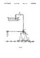
- FIG. 1is a side elevational view of the printed circuit board cleaning apparatus in accordance with the invention.
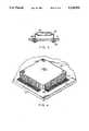
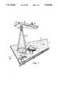
- FIG. 2is a perspective view of the printed circuit board cleaning apparatus of FIG. 1, wherein the printed circuit board in the drawing has been shown in a non-parallel relation to the solution delivery manifold for ease of depiction;
- FIG. 3is an enlarged sectional view of a printed circuit board with a typical component assembled thereto by the traditional through hole process
- FIG. 4is a perspective view of a printed circuit board with an integrated circuit component having outside leads assembled thereto by a surface mounting process
- FIG. 5is an enlarged sectional view of a printed circuit board with an integrated circuit component having underneath leads assembled thereto by a surface mounting process
- FIG. 6is an enlarged sectional view of a printed circuit board with a discrete, leadless component assembled thereto by a surface mounting process
- FIG. 7is a perspective view showing a portion of the solution delivery manifold relative to a printed circuit board surface to diagrammatically illustrate the fluid flow path of the aqueous solution;
- FIG. 8is a cross-sectional view of a spray pattern relative to a testing location for performance of spray tests
- FIG. 9is a diagrammatic representation of coordinates for purposes of explanation of test results.
- FIG. 10is a plan diagrammatic view of the annulus formed by the spray pattern of FIG. 8.
- a printed circuit board 11has integrated circuit components 12 and discrete components 29 mounted thereon.
- the integrated circuit components 12each have a plurality of electrically conductive leads 13 emanating from the side panels thereof, the leads 13 having been attached to the printed circuit board 11 by conventional surface mount techniques.
- the discrete components 29, on the other hand,have metal ends 30, not leads, terminating the ends thereof, the metal ends 30 having also been attached to printed circuit board 11 by known surface mount techniques.
- the printed circuit board 11is of the conventional type, that is, a two sided, generally planar plate shaped member consisting of an insulative substrate having conductive lamina surfaces on opposite surfaces thereof, with selected portions of the conductive lamina removed to define conductive paths between the various components assembled thereon.
- the board 11may also have numerous internal conductive and non-conductive layers sandwiched between the outer, opposite surfaces on which components 12 and 29 are mounted.
- the conductive portionsdefine pads 27 on which the leads 13 of integrated circuit components 12 and ends 30 of discrete components 29 are positioned, and, as part of such assembly, a solder flux paste 26 is applied and subsequently becomes hardened by exposure of the board 11 and assembled components to heat, which is necessary to melt and flow the solder.
- the process of surface mounting of discrete components 29 to the printed circuit board 11will typically result in spacing between the lower surface of component 29 and the adjacent surface of board 11 of small dimensions which, by way of example, is in the order of 0.004". Although the spacing between the lower surface of integrated circuit component 12 and the adjacent surface of board 11 is approximately 0.050", the spacing between adjacent leads 13 of integrated circuit 12 may result in dimensions in the order of 0.006". These extremely small areas are prone to entrap hardened solder flux. These areas are also typically beneath the infiltration threshold of cleaning solutions in prior processes. Nevertheless, the combination defined herein provides a means for quality cleaning of such surface mounted printed circuit boards without the use of objectionable solvents.
- FIG. 3a traditional through hole mounting technique is depicted, and, as shown, the resulting spacing between typical component 40 and board 11 is relatively large.
- the processis based on the drilling of hole 25 in board 11 and passing leads 43 there in, thereafter causing predeposited solder 28 to melt and to create a mechanical bond and electrical connection between leads 43 and the circuit pattern laminated to board 11.
- predeposited solder 28As component 40 is placed upon printed circuit board 11 with leads 43 in the holes 25, relative movement is not likely and the use of a liquid solder flux is satisfactory. Consequently, the flux does not harden after soldering and is not difficult to remove by conventional washing or cleaning techniques, which reach most areas that require cleaning since these areas are exposed and accessible.
- the leads 13 of integrated circuit component 12emanate from the side panels of integrated circuit 12 and pass downwardly to a point where they are redirected outwardly in a plane parallel to the major surfaces of component 12 (known as a gull-wing leaded component).
- the printed circuit board 11is laminated with lead mounting pads 27 onto which the leads 13 of integrated circuit component 12 are placed, without the aid of through holes.
- a flux in a paste formis used, rather than a liquid, the paste 26 having somewhat adhesive characteristics to enable positioning and retention of the component 12 during assembly of all integrated circuit components 12 onto the surface of the printed circuit board 11.
- the flux paste 26is typically mixed to include the solder so as to avoid the need for an extra step.
- the assemblyis then exposed to heat to permanently bond the component leads 13 to the pads 27.
- heatwhich must be in excess of 361° F. and for a duration of sixty to ninety seconds
- the solder in paste 26will melt to connect the leads 13 of the integrated circuit 12 to board 11.
- the paste 26will cure or harden, creating a residue that is difficult to remove from a small space, for example, space 60 between adjacent leads 13.
- the dimension of space 60may be in the order of 0.006".
- FIG. 5illustrates an alternate style of surface mounted technique which enables closer spacing between adjacent components.
- the integrated circuit component 12has leads 13 that emanate from the sides of the integrated circuit 12 and pass downwardly to a point, at least to the lowest level of integrated circuit 12 where they are redirected under the component 12, that is, inwardly along and beneath the lower surface of the integrated circuit component 12 or slightly spaced therefrom (known as J-bend leaded component).
- the assembly and soldering process as described in FIG. 4is then performed. While the space between the lower surface of integrated circuit 12 and the adjacent surface of the board 11 is greater than the spacing of the outwardly disposed leads 13 of the integrated circuit component 12 of FIG. 4, the spacing between adjacent leads 13 remains small and shelters small spaces from easy cleaning.
- FIG. 6shows an additional surface mounted technique in which the metal ends 30 of the discrete, leadless component 29 are soldered directly to mounting pads 27, without any additions or alterations to the ends 30. Accordingly, the resulting space 32 between the lower surface of discrete component 29 and the adjacent surface of printed circuit board 11 is in the order of 0.004", which is much smaller than that of integrated circuit components 12 of FIGS. 4 and 5.
- the spacing 60 between adjacent leads 13 on the same integrated circuit component 12are very small, while the spacing 32 between the lower surface of discrete component 29 and the adjacent surface of the printed circuit board 11 is likewise very small. In any case, the spacing between leads 13 and ends 30 on adjacent components are very small.
- Such close tolerances and spacingcreate major hurdles to the use of conventional cleaning techniques in the removal of particulate residue of the solid matter remaining after the assembly and heating process.
- the cleaning apparatusincludes a liquid reservoir 15, from which a solution is transported by a pump 16 through tubing to a rotatable delivery manifold 19, which is of a generally elongate configuration rotatable about its approximate geometrical center, defined by inlet 18, by means of a motor arrangement 21.
- a rotatable delivery manifold 19Affixed to the underside of opposite ends of the manifold 19 are first and second nozzles 20, each of which is substantially equidistant from the axis of rotation of the manifold 19.
- the manifold 19is configured, dimensioned and arranged to rotate in a plane generally parallel to the plane of the printed circuit board 11, that is, in a plane generally parallel to the plane of the conveyor 14.
- the manifold 19could be constructed as an arm which supplies structured support and movement to nozzles 20 and the solution could be delivered to the nozzles 20 via ducts or tubes, if desired.
- the printed circuit board 11, with components 12 and 29 mounted thereon by use of the flux paste 26,is transported in a plane perpendicular to the axis of rotation of the manifold 19 by means of a conveyor 14 of conventional construction.
- the conveyor 14transports the component-assembled printed circuit board 11 along a path generally coinciding with the center line 24 of the apparatus.
- the conveyor 14is constructed and operated to move one or more printed circuit boards 11 past one or more stations in the manufacturing process which may include the steps of heat/solder, wash, rinse, and dry.
- the spacing in the vertical direction between the lowest point of the nozzles 20 and the plane of the printed circuit board 11is chosen to provide the optimum cleaning fluid force at the printed circuit board 11 in the flow pattern desired, as will be hereinafter described.
- the liquid reservoir 15 and pump 16may be physically located in any convenient location.
- the reservoir 15includes a heating device or structure (not shown) for providing a heated aqueous solution for use in the printed circuit board cleaning process.
- the pump 16is capable of delivering fluid at a high pressure through the manifold 19 and nozzle 20 assembly. Alternatively, a cleaning fluid may be supplied to the nozzles 20 by whatever means desired.
- the cleaning apparatusobtains the solution from heating reservoir 15 through suitable piping to a high pressure pump 16, which pumps the solution at a pre-selected high pressure, in the range of 250 to 500 psi, through a suitable rotatable pressure seal 17 into inlet 18 to manifold 19 to discharge through one or more nozzles 20.
- the heating reservoir 15is capable of maintaining the solution at a temperature of between 140° F. and 160° F., with the reservoir 15 having sufficient capacity to heat the quantity of solution passing through the washing process.
- the manifold 19is caused to oscillate or rotate about the inlet 18 by any suitable means, such as a motor, pulley and drive belt arrangement 21, at a rotational or oscillational speed of between fifteen and thirty rpm. A direct drive gear motor configuration could also be used. During this rotation, the heated solution is sprayed upon the printed circuit board 11 through nozzles 20, which are of a helically-vaned type design.
- the helically-vaned nozzle 20is configured for producing a cone-shaped spray stream 22 of highly atomized droplets, the spray stream 22 having an included angle of between 50° and 90°, that is 25° to 45° to the axis of the cone-shaped stream 22.
- Other anglescould, of course, be used without deviating from the inventive concepts described herein as would be apparent to one of ordinary skill in the art.
- Tables 1-4summarize composite droplet size testing results of spray stream 22 produced by helically-vaned nozzle 20.
- the conditions for the droplet size testsincluded use of a solution composed solely of water pumped at various pressures through a single-turn, helically-vaned nozzle 20 having an included angle of 50°.
- Centerline 80, radius 82, azimuthal angle 84, and cylindrical angle 90are additional conditions and variables graphically depicted in FIGS. 8 and 9. Referring to Test 4A as an illustrative example of the testing performed, water is pumped at a pressure of 500 psi through nozzle 20.
- Centerline 80which represents the perpendicular distance from nozzle 20 to the printed circuit board 11, is 4.0 inches, while radius 82, the radial coordinate of actual testing and sampling, is 2.1 inches.
- the azimuthal angle 84is defined as the included angle from centerline 80 to radius 82 and is 27.7°, while the cylindrical angle 90, the point of measurement around annulus 35 (see FIG. 7) of spray stream 22, is 0°.
- the spray stream 22is shown impacting board 11 at an annulus 35.
- the spray stream 22may be either full or hollow, that is, the size of the annulus 35 impacting printed circuit board 11 may be either large (i.e. use of a full-cone or two-turn spiral nozzle) or narrow (i.e. use of a hollow-cone or single-turn nozzle).
- the hollow cone-shaped patternis preferred for use with surface mounted components.
- a nozzle found to be satisfactory in the apparatus of the inventionis Type TF-N, shown and described on page 17 in Catalog 891 of Bete Fog Nozzle Inc., of Greenfield, MA, which catalog is hereby expressly incorporated by reference as though fully set forth herein.
- a nozzle of this typeis shown and described in U.S. Pat. No. 2,804,341 issued to John U. Bete on Aug. 27, 1957, which patent is also expressly incorporated by reference as though fully set forth herein.
- the manifold 19is of a configuration and length to mount a predetermined number of helically-vaned nozzles 20, which may be one or more, and dispense the solution over all areas of the surface of the printed circuit board 11 to achieve thorough cleaning.
- the nozzles 20are mounted on the lower outer ends of the manifold 19, and aimed downwardly at the printed circuit board 11.
- the rotating velocity of the manifold 19may be adjusted to compensate for a different radius from the center of manifold 19 to the nozzles 20 for proper cleaning spray distribution.
- nozzles 20The determination of the number of nozzles 20 to use in the apparatus taught herein will depend on a variety of factors, including cycle speed (time required for cleaning the board 11), overall dimensions of the printed circuit board 11, operating pressure and volumetric discharge capacity of the pump 16, and the heat generating capacity of the reservoir 15. Two or four nozzles have been used successfully, but are not the only numbers which are contemplated to perform within the principles of this invention.
- the apparatus according to the inventionis shown in projection from an observation point of a height between the main sections of the apparatus, that is, the plane of the printed circuit board 11 and the conveyor 14 as well as the underside of the manifold 19 can be seen.
- This figureshows a manifold 19 of generally elongate configuration having two oppositely disposed radially equidistant nozzles 20.
- the selected number of helically-vaned nozzles 20, the speed of rotation of manifold 19, the speed of movement of conveyor 14, the pressure of solution from the pump 16 and various other parametersare to be balanced to produce optimum results.
- the use of two oppositely disposed radially equidistant nozzles 20facilitates draining of the solution spray stream 22 from an area of impact on printed circuit board 11 before the next rotating spray stream 22 impinges upon that area.
- FIG. 7shows the pattern of the cone-shaped spray stream 22 impacting printed circuit board 11 and thence, in accordance with the principles of the invention, transforming the linear momentum of the high pressure spray stream 22 upon the plane of the surface of board 11 together with certain velocity vectors into an outwardly dispersing, forceful flushing pattern 23 of solution across printed circuit board 11.
- the resultant flushing pattern 23is characterized by a changing of the velocity vectors above the plane of the surface of board 11.
- the geometry of the cone-shaped spray stream 22is a function of the helically-vaned nozzle 20 used in the cleaning apparatus, which nozzle 20 may be defined by the droplet size of the resultant spray, in addition to the density and impingement angle of the spray upon the surface of board 11.
- the velocity vectorsare characterized by the geometry of the spray stream 22, the rotation of manifold 19, and the movement of board 11 on the conveyor 14, all of which contribute to an angle of incidence other than 90° perpendicular to the impact of the spray stream 22 upon printed circuit board 11. That is, the combined movement of the manifold 19 and board 11 on the conveyor 14 effects a constantly changing spray direction at the point of impact of the stream 22 with an obstacle, such as hardened flux paste, a lead, or any other obstruction against which debris may lodge.
- an obstaclesuch as hardened flux paste, a lead, or any other obstruction against which debris may lodge.
- the combination of the cone-shaped spray geometry and velocity componentsgenerates an active cleaning means along the surface of board 11, so that the spray stream 22 is capable of forcibly infiltrating minuscule spaces, such as the clearance between discrete component 29 and printed circuit board 11 and between adjacent leads 13 of integrated circuit component 12, thereby dislodging hardened flux from anywhere on board 11 without the use of solvents.
- the flow of the solution, upon impact with board 11,is in a direction parallel to the plane of the printed circuit board 11 and does not follow the "spray and bounce" flow pattern of prior art methods.
- the aqueous solution used for the cleaning and dissolving of conventional, surface mount solder flux paste 26typically includes a solvent to facilitate the removal of residues that are oils and terpenes in nature, a saponification agent to react with the rosin component of the congealed flux residues, and an anti-foaming agent to minimize resultant foam.
- These chemical additivesare normally used in manufacturing and readily available from a variety of commercial sources. An optimum solution effectiveness is obtained by applying the additives (in concentrate form) in the order of 3 to 7 percent of the total aqueous solution at an operating temperature of 155° ⁇ 5° F.
- alternative cleaning fluidsmay be used, water based solutions are found to be least damaging environmentally and highly desirable. Use of this invention for chlorofluorocarbon based solutions should work well, but the inventors believe a feature of the invention lies in obviating the need to use such solvents for cleaning.
- the aqueous solutioncontains 7% concentrate, which includes a solvent, a saponification agent and an anti-foaming agent, and 93% water heated to a temperature of about 155° F.
- the solutionis pumped at a pressure of 500 psi and delivered to the manifold 19 having two helically-vaned nozzles 20 that generate a hollow cone-shaped spray stream 22 of about 50° included angle directed at the surface of printed circuit board 11.
- the manifold 19is rotated in a counter-clockwise direction (viewed from above) at a rate of twenty rpm and at a height of about four inches above the surface to be cleaned.
- Printed circuit board 11is moved by a conveyor 14 traveling at a speed of about three feet per minute.
- the inventionis applicable to water-soluble solder paste used for the surface mounting of components upon printed circuit boards.
- watermay be the preferred cleaning fluid within the teaching of this invention.
Landscapes
- Engineering & Computer Science (AREA)
- Manufacturing & Machinery (AREA)
- Microelectronics & Electronic Packaging (AREA)
- Electric Connection Of Electric Components To Printed Circuits (AREA)
Abstract
Description
TABLE 1 ______________________________________ TESTS: 1A 1B 1C 1D ______________________________________ PRESSURE (PSI): 200 200 200 200 CENTERLINE (INCHES): 4.0 4.0 4.0 4.0 RADIUS (INCHES): 2.0 1.0 1.5 1.5 AZIMUTHAL ANGLE (%): 26.6 14.0 20.6 20.6 CYLINDRICAL 0 180 90 270 ANGLE (%): ______________________________________ DIAMETER DROPS OCCURRENCE (microns) (number) (%) ______________________________________ 6.3-7.9 990 29.36 7.9-10.0 442 13.11 10.0-12.6 384 11.39 12.6-15.8 239 7.09 15.8-20.0 254 7.53 20.0-25.1 203 6.02 25.1-31.6 168 4.98 31.6-39.8 110 3.26 39.8-50.1 138 4.09 50.1-63.1 106 3.14 63.1-79.4 106 3.14 79.4-100.0 79 2.34 100.0-125.9 64 1.90 125.9-158.5 49 1.45 158.5-199.5 24 0.71 199.5-251.2 12 0.36 251.2-316.2 3 0.09 316.2-398.1 1 0.03 3372 100.0 ______________________________________
TABLE 2 ______________________________________ TESTS: 2A 2B 2C 2D ______________________________________ PRESSURE (PSI): 300 300 300 300 CENTERLINE (INCHES): 4.0 4.0 4.0 4.0 RADIUS (INCHES): 1.5 1.5 1.0 2.0 AZIMUTHAL ANGLE (%): 20.6 20.6 14.0 26.6 CYLINDRICAL 270 90 180 0 ANGLE (%): ______________________________________ DIAMETER DROPS OCCURRENCE (microns) (number) (%) ______________________________________ 6.3-7.9 958 35.04 7.9-10.0 362 13.24 10.0-12.6 315 11.52 12.6-15.8 208 7.61 15.8-20.0 203 7.43 20.0-25.1 149 5.45 25.1-31.6 123 4.50 31.6-39.8 93 3.40 39.8-50.1 102 3.73 50.1-63.1 73 2.67 63.1-79.4 57 2.08 79.4-100.0 44 1.61 100.0-125.9 21 0.77 125.9-158.5 13 0.48 158.5-199.5 9 0.33 199.5-251.2 4 0.15 2734 100.0 ______________________________________
TABLE 3 ______________________________________ TESTS: 3A 3B 3C 3D ______________________________________ PRESSURE (PSI): 400 400 400 400 CENTERLINE (INCHES): 4.0 4.0 4.0 4.0 RADIUS (INCHES): 1.5 1.5 1.5 2.0 AZIMUTHAL ANGLE (%): 20.6 20.6 20.6 26.6 CYLINDRICAL 270 90 180 0 ANGLE (%): ______________________________________ DIAMETER DROPS OCCURRENCE (microns) (number) (%) ______________________________________ 6.3-7.9 735 31.09 7.9-10.0 305 12.90 10.0-12.6 289 12.23 12.6-15.8 196 8.29 15.8-20.0 157 6.64 20.0-25.1 96 4.06 25.1-31.6 102 4.31 31.6-39.8 95 4.02 39.8-50.1 100 4.23 50.1-63.1 97 4.10 63.1-79.4 66 2.79 79.4-100.0 58 2.45 100.0-125.9 39 1.65 125.9-158.5 17 0.72 158.5-199.5 9 0.38 199.5-251.2 3 0.13 2364 100.0 ______________________________________
TABLE 4 ______________________________________ TESTS: 4A 4B 4C 4D ______________________________________ PRESSURE (PSI): 500 500 500 500 CENTERLINE (INCHES): 4.0 4.0 4.0 4.0 RADIUS (INCHES): 2.1 1.3 1.8 1.3 AZIMUTHAL ANGLE (%): 27.7 18.0 24.2 18.0 CYLINDRICAL 0 180 270 90 ANGLE (%): ______________________________________ DIAMETER DROPS OCCURRENCE (microns) (number) (%) ______________________________________ 6.3-7.9 757 33.99 7.9-10.0 285 12.80 10.0-12.6 243 10.91 12.6-15.8 167 7.50 15.8-20.0 167 7.50 20.0-25.1 114 5.12 25.1-31.6 102 4.58 31.6-39.8 93 4.18 39.8-50.1 86 3.86 50.1-63.1 82 3.68 63.1-79.4 58 2.60 79.4-100.0 38 1.71 100.0-125.9 27 1.21 125.9-158.5 6 0.27 158.5-199.5 2 0.09 2227 100.0 ______________________________________
Claims (14)
Priority Applications (1)
| Application Number | Priority Date | Filing Date | Title |
|---|---|---|---|
| US07/417,937US5129956A (en) | 1989-10-06 | 1989-10-06 | Method and apparatus for the aqueous cleaning of populated printed circuit boards |
Applications Claiming Priority (1)
| Application Number | Priority Date | Filing Date | Title |
|---|---|---|---|
| US07/417,937US5129956A (en) | 1989-10-06 | 1989-10-06 | Method and apparatus for the aqueous cleaning of populated printed circuit boards |
Publications (1)
| Publication Number | Publication Date |
|---|---|
| US5129956Atrue US5129956A (en) | 1992-07-14 |
Family
ID=23655973
Family Applications (1)
| Application Number | Title | Priority Date | Filing Date |
|---|---|---|---|
| US07/417,937Expired - LifetimeUS5129956A (en) | 1989-10-06 | 1989-10-06 | Method and apparatus for the aqueous cleaning of populated printed circuit boards |
Country Status (1)
| Country | Link |
|---|---|
| US (1) | US5129956A (en) |
Cited By (48)
| Publication number | Priority date | Publication date | Assignee | Title |
|---|---|---|---|---|
| US5339843A (en)* | 1993-04-16 | 1994-08-23 | Martin Marietta Corporation | Controlled agitation cleaning system |
| US5364474A (en)* | 1993-07-23 | 1994-11-15 | Williford Jr John F | Method for removing particulate matter |
| US5368054A (en)* | 1993-12-17 | 1994-11-29 | International Business Machines Corporation | Ultrasonic jet semiconductor wafer cleaning apparatus |
| US5483871A (en)* | 1994-02-24 | 1996-01-16 | Sunkist Growers, Inc. | Apparatus for spray washing fruit in a brush bed |
| US5524654A (en)* | 1994-01-13 | 1996-06-11 | Kabushi Gaisha Ishii Hyoki | Etching, developing and peeling apparatus for printed board |
| WO1997042373A1 (en)* | 1996-05-09 | 1997-11-13 | Robo Paper Engineering B.V. | Cleaning device for cleaning a dewatering screen in a wet or dry section or a wet felt in a press section of a paper making machine |
| US5701654A (en)* | 1995-06-07 | 1997-12-30 | International Business Machines Corporation | Precision fluid head transport |
| US5810942A (en)* | 1996-09-11 | 1998-09-22 | Fsi International, Inc. | Aerodynamic aerosol chamber |
| US5913354A (en)* | 1995-05-22 | 1999-06-22 | Howmet Research Corporation | Removal of ceramic shell mold material from castings |
| US5942037A (en)* | 1996-12-23 | 1999-08-24 | Fsi International, Inc. | Rotatable and translatable spray nozzle |
| US5961732A (en)* | 1997-06-11 | 1999-10-05 | Fsi International, Inc | Treating substrates by producing and controlling a cryogenic aerosol |
| US6036786A (en)* | 1997-06-11 | 2000-03-14 | Fsi International Inc. | Eliminating stiction with the use of cryogenic aerosol |
| US6039059A (en)* | 1996-09-30 | 2000-03-21 | Verteq, Inc. | Wafer cleaning system |
| US6092537A (en)* | 1995-01-19 | 2000-07-25 | Mitsubishi Denki Kabushiki Kaisha | Post-treatment method for dry etching |
| US6332470B1 (en)* | 1997-12-30 | 2001-12-25 | Boris Fishkin | Aerosol substrate cleaner |
| US20050028846A1 (en)* | 2001-05-04 | 2005-02-10 | Fratello Daniel A. | Fluid emitting nozzles for use with vehicle wash apparatus |
| US20060225851A1 (en)* | 2005-04-06 | 2006-10-12 | Hsien-Hsin Chiu | Chip washing apparatus |
| US7951244B2 (en) | 2008-01-11 | 2011-05-31 | Illinois Tool Works Inc. | Liquid cleaning apparatus for cleaning printed circuit boards |
| CN102744168A (en)* | 2012-06-15 | 2012-10-24 | 无锡翱翔环保机械有限公司 | Supply water spray head for thermal deaerator |
| US20150224548A1 (en)* | 2014-02-07 | 2015-08-13 | Japan Display Inc. | Manufacturing method and manufacturing apparatus of liquid crystal display device |
| TWI508795B (en)* | 2009-11-03 | 2015-11-21 | Arakawa Chem Ind | Cleaning device for electronic parts and cleaning method |
| US20160320213A1 (en)* | 2014-01-24 | 2016-11-03 | Shenzhen China Optoelectronics Technology Co., Ltd | Flick sensor assembly |
| CN107282502A (en)* | 2017-07-19 | 2017-10-24 | 来奇偏光科技(中国)股份有限公司 | Blooming piece cleaning device |
| CN108024451A (en)* | 2017-11-24 | 2018-05-11 | 江门市奔力达电路有限公司 | A kind of pcb board moves back oily technique |
| US10150623B2 (en)* | 2016-06-16 | 2018-12-11 | Keith David Handy | Cleaning apparatus |
| CN110813617A (en)* | 2019-11-21 | 2020-02-21 | 泗县腾马汽车配件有限公司 | Filter stoving assembly line that dusts |
| WO2020112784A1 (en)* | 2018-11-30 | 2020-06-04 | Mega Fluid Systems, Inc. | Apparatus and method for recirculating fluids |
| CN112090639A (en)* | 2020-09-23 | 2020-12-18 | 滁州市友邦涂装有限公司 | Auto-parts makes and uses automatic spraying device |
| CN112367765A (en)* | 2020-10-19 | 2021-02-12 | 绍兴上虞锴达电子有限公司 | High-resistance insulated circuit board manufacturing equipment |
| US11136849B2 (en) | 2019-11-05 | 2021-10-05 | Saudi Arabian Oil Company | Dual string fluid management devices for oil and gas applications |
| US11156052B2 (en) | 2019-12-30 | 2021-10-26 | Saudi Arabian Oil Company | Wellbore tool assembly to open collapsed tubing |
| US11225850B2 (en) | 2019-11-04 | 2022-01-18 | Saudi Arabian Oil Company | Cutting a tubular in a wellbore |
| US11230904B2 (en) | 2019-11-11 | 2022-01-25 | Saudi Arabian Oil Company | Setting and unsetting a production packer |
| US11253819B2 (en) | 2020-05-14 | 2022-02-22 | Saudi Arabian Oil Company | Production of thin film composite hollow fiber membranes |
| US11260351B2 (en) | 2020-02-14 | 2022-03-01 | Saudi Arabian Oil Company | Thin film composite hollow fiber membranes fabrication systems |
| US11448026B1 (en) | 2021-05-03 | 2022-09-20 | Saudi Arabian Oil Company | Cable head for a wireline tool |
| US11549329B2 (en) | 2020-12-22 | 2023-01-10 | Saudi Arabian Oil Company | Downhole casing-casing annulus sealant injection |
| US11598178B2 (en) | 2021-01-08 | 2023-03-07 | Saudi Arabian Oil Company | Wellbore mud pit safety system |
| US11655685B2 (en) | 2020-08-10 | 2023-05-23 | Saudi Arabian Oil Company | Downhole welding tools and related methods |
| US11828128B2 (en) | 2021-01-04 | 2023-11-28 | Saudi Arabian Oil Company | Convertible bell nipple for wellbore operations |
| US11859815B2 (en) | 2021-05-18 | 2024-01-02 | Saudi Arabian Oil Company | Flare control at well sites |
| US11858091B2 (en) | 2018-11-30 | 2024-01-02 | Mega Fluid Systems, Inc. | Apparatus and method for recirculating fluids |
| US11905791B2 (en) | 2021-08-18 | 2024-02-20 | Saudi Arabian Oil Company | Float valve for drilling and workover operations |
| US11913298B2 (en) | 2021-10-25 | 2024-02-27 | Saudi Arabian Oil Company | Downhole milling system |
| US11993992B2 (en) | 2022-08-29 | 2024-05-28 | Saudi Arabian Oil Company | Modified cement retainer with milling assembly |
| US12054999B2 (en) | 2021-03-01 | 2024-08-06 | Saudi Arabian Oil Company | Maintaining and inspecting a wellbore |
| US12116326B2 (en) | 2021-11-22 | 2024-10-15 | Saudi Arabian Oil Company | Conversion of hydrogen sulfide and carbon dioxide into hydrocarbons using non-thermal plasma and a catalyst |
| US12276190B2 (en) | 2022-02-16 | 2025-04-15 | Saudi Arabian Oil Company | Ultrasonic flow check systems for wellbores |
Citations (10)
| Publication number | Priority date | Publication date | Assignee | Title |
|---|---|---|---|---|
| US2804341A (en)* | 1956-04-13 | 1957-08-27 | Bete Fog Nozzle Inc | Spray nozzles |
| US3177095A (en)* | 1961-01-23 | 1965-04-06 | G M Gibson Corp | Method for washing articles |
| US3432346A (en)* | 1963-04-24 | 1969-03-11 | Johnson & Son Inc S C | Automobile washing method |
| US3483616A (en)* | 1964-01-23 | 1969-12-16 | Sanders Associates Inc | Method for producing a printed circuit board |
| US3755886A (en)* | 1971-10-22 | 1973-09-04 | Magnavox Co | Method for soldering electrical conductors |
| US3868272A (en)* | 1973-03-05 | 1975-02-25 | Electrovert Mfg Co Ltd | Cleaning of printed circuit boards by solid and coherent jets of cleaning liquid |
| US4102350A (en)* | 1976-11-29 | 1978-07-25 | The Continental Group, Inc. | Apparatus for removing excess coating material accumulated at the interior edge portions of metal containers |
| US4342425A (en)* | 1980-04-10 | 1982-08-03 | Her Majesty The Queen In Right Of Canada, As Represented By The Minister Of National Defence | Cavitation nozzle assembly |
| US4537639A (en)* | 1983-09-12 | 1985-08-27 | Nlb Corp. | Method for cleaning weld smut from a surface |
| GB2197581A (en)* | 1986-11-21 | 1988-05-25 | Teledyne Ind | Cleaning of printed circuit panels |
- 1989
- 1989-10-06USUS07/417,937patent/US5129956A/ennot_activeExpired - Lifetime
Patent Citations (10)
| Publication number | Priority date | Publication date | Assignee | Title |
|---|---|---|---|---|
| US2804341A (en)* | 1956-04-13 | 1957-08-27 | Bete Fog Nozzle Inc | Spray nozzles |
| US3177095A (en)* | 1961-01-23 | 1965-04-06 | G M Gibson Corp | Method for washing articles |
| US3432346A (en)* | 1963-04-24 | 1969-03-11 | Johnson & Son Inc S C | Automobile washing method |
| US3483616A (en)* | 1964-01-23 | 1969-12-16 | Sanders Associates Inc | Method for producing a printed circuit board |
| US3755886A (en)* | 1971-10-22 | 1973-09-04 | Magnavox Co | Method for soldering electrical conductors |
| US3868272A (en)* | 1973-03-05 | 1975-02-25 | Electrovert Mfg Co Ltd | Cleaning of printed circuit boards by solid and coherent jets of cleaning liquid |
| US4102350A (en)* | 1976-11-29 | 1978-07-25 | The Continental Group, Inc. | Apparatus for removing excess coating material accumulated at the interior edge portions of metal containers |
| US4342425A (en)* | 1980-04-10 | 1982-08-03 | Her Majesty The Queen In Right Of Canada, As Represented By The Minister Of National Defence | Cavitation nozzle assembly |
| US4537639A (en)* | 1983-09-12 | 1985-08-27 | Nlb Corp. | Method for cleaning weld smut from a surface |
| GB2197581A (en)* | 1986-11-21 | 1988-05-25 | Teledyne Ind | Cleaning of printed circuit panels |
Non-Patent Citations (2)
| Title |
|---|
| "Aqueous Cleaning Power" by Janet R. Sterritt, from Printed Circuit Assembly Magazine, Sep., 1989 issue at pp. 26-29. |
| Aqueous Cleaning Power by Janet R. Sterritt, from Printed Circuit Assembly Magazine, Sep., 1989 issue at pp. 26 29.* |
Cited By (69)
| Publication number | Priority date | Publication date | Assignee | Title |
|---|---|---|---|---|
| US5339843A (en)* | 1993-04-16 | 1994-08-23 | Martin Marietta Corporation | Controlled agitation cleaning system |
| US5364474A (en)* | 1993-07-23 | 1994-11-15 | Williford Jr John F | Method for removing particulate matter |
| US5558110A (en)* | 1993-07-23 | 1996-09-24 | Williford, Jr.; John F. | Apparatus for removing particulate matter |
| US5368054A (en)* | 1993-12-17 | 1994-11-29 | International Business Machines Corporation | Ultrasonic jet semiconductor wafer cleaning apparatus |
| US5524654A (en)* | 1994-01-13 | 1996-06-11 | Kabushi Gaisha Ishii Hyoki | Etching, developing and peeling apparatus for printed board |
| US5483871A (en)* | 1994-02-24 | 1996-01-16 | Sunkist Growers, Inc. | Apparatus for spray washing fruit in a brush bed |
| US6092537A (en)* | 1995-01-19 | 2000-07-25 | Mitsubishi Denki Kabushiki Kaisha | Post-treatment method for dry etching |
| US5913354A (en)* | 1995-05-22 | 1999-06-22 | Howmet Research Corporation | Removal of ceramic shell mold material from castings |
| US5762082A (en)* | 1995-06-07 | 1998-06-09 | International Business Machines Corporation | Precision fluid head transport |
| US5701654A (en)* | 1995-06-07 | 1997-12-30 | International Business Machines Corporation | Precision fluid head transport |
| EP0748150A3 (en)* | 1995-06-07 | 1998-09-23 | International Business Machines Corporation | Precision fluid head transport |
| US5837067A (en)* | 1995-06-07 | 1998-11-17 | International Business Machines Corporation | Precision fluid head transport |
| NL1003070C2 (en)* | 1996-05-09 | 1997-11-18 | Robo Paper Engineering B V | Cleaning device for cleaning a dewatering screen in a wet or dry lot or a wet felt in a press lot of a papermaking machine. |
| WO1997042373A1 (en)* | 1996-05-09 | 1997-11-13 | Robo Paper Engineering B.V. | Cleaning device for cleaning a dewatering screen in a wet or dry section or a wet felt in a press section of a paper making machine |
| US5810942A (en)* | 1996-09-11 | 1998-09-22 | Fsi International, Inc. | Aerodynamic aerosol chamber |
| US8257505B2 (en) | 1996-09-30 | 2012-09-04 | Akrion Systems, Llc | Method for megasonic processing of an article |
| US20060180186A1 (en)* | 1996-09-30 | 2006-08-17 | Bran Mario E | Transducer assembly for megasonic processing of an article |
| US6039059A (en)* | 1996-09-30 | 2000-03-21 | Verteq, Inc. | Wafer cleaning system |
| US8771427B2 (en) | 1996-09-30 | 2014-07-08 | Akrion Systems, Llc | Method of manufacturing integrated circuit devices |
| US6140744A (en)* | 1996-09-30 | 2000-10-31 | Verteq, Inc. | Wafer cleaning system |
| US6295999B1 (en) | 1996-09-30 | 2001-10-02 | Verteq, Inc. | Wafer cleaning method |
| US7518288B2 (en) | 1996-09-30 | 2009-04-14 | Akrion Technologies, Inc. | System for megasonic processing of an article |
| US6463938B2 (en) | 1996-09-30 | 2002-10-15 | Verteq, Inc. | Wafer cleaning method |
| US6681782B2 (en) | 1996-09-30 | 2004-01-27 | Verteq, Inc. | Wafer cleaning |
| US6684891B2 (en) | 1996-09-30 | 2004-02-03 | Verteq, Inc. | Wafer cleaning |
| US20040206371A1 (en)* | 1996-09-30 | 2004-10-21 | Bran Mario E. | Wafer cleaning |
| US7268469B2 (en) | 1996-09-30 | 2007-09-11 | Akrion Technologies, Inc. | Transducer assembly for megasonic processing of an article and apparatus utilizing the same |
| US20060175935A1 (en)* | 1996-09-30 | 2006-08-10 | Bran Mario E | Transducer assembly for megasonic processing of an article |
| US7211932B2 (en) | 1996-09-30 | 2007-05-01 | Akrion Technologies, Inc. | Apparatus for megasonic processing of an article |
| US7117876B2 (en) | 1996-09-30 | 2006-10-10 | Akrion Technologies, Inc. | Method of cleaning a side of a thin flat substrate by applying sonic energy to the opposite side of the substrate |
| US5942037A (en)* | 1996-12-23 | 1999-08-24 | Fsi International, Inc. | Rotatable and translatable spray nozzle |
| US5961732A (en)* | 1997-06-11 | 1999-10-05 | Fsi International, Inc | Treating substrates by producing and controlling a cryogenic aerosol |
| US6036786A (en)* | 1997-06-11 | 2000-03-14 | Fsi International Inc. | Eliminating stiction with the use of cryogenic aerosol |
| US6332470B1 (en)* | 1997-12-30 | 2001-12-25 | Boris Fishkin | Aerosol substrate cleaner |
| US20050028846A1 (en)* | 2001-05-04 | 2005-02-10 | Fratello Daniel A. | Fluid emitting nozzles for use with vehicle wash apparatus |
| US20060225851A1 (en)* | 2005-04-06 | 2006-10-12 | Hsien-Hsin Chiu | Chip washing apparatus |
| US7951244B2 (en) | 2008-01-11 | 2011-05-31 | Illinois Tool Works Inc. | Liquid cleaning apparatus for cleaning printed circuit boards |
| TWI508795B (en)* | 2009-11-03 | 2015-11-21 | Arakawa Chem Ind | Cleaning device for electronic parts and cleaning method |
| CN102744168A (en)* | 2012-06-15 | 2012-10-24 | 无锡翱翔环保机械有限公司 | Supply water spray head for thermal deaerator |
| US20160320213A1 (en)* | 2014-01-24 | 2016-11-03 | Shenzhen China Optoelectronics Technology Co., Ltd | Flick sensor assembly |
| US20150224548A1 (en)* | 2014-02-07 | 2015-08-13 | Japan Display Inc. | Manufacturing method and manufacturing apparatus of liquid crystal display device |
| US10150623B2 (en)* | 2016-06-16 | 2018-12-11 | Keith David Handy | Cleaning apparatus |
| CN107282502A (en)* | 2017-07-19 | 2017-10-24 | 来奇偏光科技(中国)股份有限公司 | Blooming piece cleaning device |
| CN108024451A (en)* | 2017-11-24 | 2018-05-11 | 江门市奔力达电路有限公司 | A kind of pcb board moves back oily technique |
| JP2022510871A (en)* | 2018-11-30 | 2022-01-28 | メガ・フルイド・システムズ・インク | Devices and methods for recirculating fluids |
| WO2020112784A1 (en)* | 2018-11-30 | 2020-06-04 | Mega Fluid Systems, Inc. | Apparatus and method for recirculating fluids |
| US11858091B2 (en) | 2018-11-30 | 2024-01-02 | Mega Fluid Systems, Inc. | Apparatus and method for recirculating fluids |
| US11225850B2 (en) | 2019-11-04 | 2022-01-18 | Saudi Arabian Oil Company | Cutting a tubular in a wellbore |
| US11136849B2 (en) | 2019-11-05 | 2021-10-05 | Saudi Arabian Oil Company | Dual string fluid management devices for oil and gas applications |
| US11230904B2 (en) | 2019-11-11 | 2022-01-25 | Saudi Arabian Oil Company | Setting and unsetting a production packer |
| CN110813617A (en)* | 2019-11-21 | 2020-02-21 | 泗县腾马汽车配件有限公司 | Filter stoving assembly line that dusts |
| CN110813617B (en)* | 2019-11-21 | 2021-07-30 | 泗县腾马汽车配件有限公司 | Filter stoving assembly line that dusts |
| US11156052B2 (en) | 2019-12-30 | 2021-10-26 | Saudi Arabian Oil Company | Wellbore tool assembly to open collapsed tubing |
| US11260351B2 (en) | 2020-02-14 | 2022-03-01 | Saudi Arabian Oil Company | Thin film composite hollow fiber membranes fabrication systems |
| US11253819B2 (en) | 2020-05-14 | 2022-02-22 | Saudi Arabian Oil Company | Production of thin film composite hollow fiber membranes |
| US11655685B2 (en) | 2020-08-10 | 2023-05-23 | Saudi Arabian Oil Company | Downhole welding tools and related methods |
| CN112090639A (en)* | 2020-09-23 | 2020-12-18 | 滁州市友邦涂装有限公司 | Auto-parts makes and uses automatic spraying device |
| CN112367765A (en)* | 2020-10-19 | 2021-02-12 | 绍兴上虞锴达电子有限公司 | High-resistance insulated circuit board manufacturing equipment |
| US11549329B2 (en) | 2020-12-22 | 2023-01-10 | Saudi Arabian Oil Company | Downhole casing-casing annulus sealant injection |
| US11828128B2 (en) | 2021-01-04 | 2023-11-28 | Saudi Arabian Oil Company | Convertible bell nipple for wellbore operations |
| US11598178B2 (en) | 2021-01-08 | 2023-03-07 | Saudi Arabian Oil Company | Wellbore mud pit safety system |
| US12054999B2 (en) | 2021-03-01 | 2024-08-06 | Saudi Arabian Oil Company | Maintaining and inspecting a wellbore |
| US11448026B1 (en) | 2021-05-03 | 2022-09-20 | Saudi Arabian Oil Company | Cable head for a wireline tool |
| US11859815B2 (en) | 2021-05-18 | 2024-01-02 | Saudi Arabian Oil Company | Flare control at well sites |
| US11905791B2 (en) | 2021-08-18 | 2024-02-20 | Saudi Arabian Oil Company | Float valve for drilling and workover operations |
| US11913298B2 (en) | 2021-10-25 | 2024-02-27 | Saudi Arabian Oil Company | Downhole milling system |
| US12116326B2 (en) | 2021-11-22 | 2024-10-15 | Saudi Arabian Oil Company | Conversion of hydrogen sulfide and carbon dioxide into hydrocarbons using non-thermal plasma and a catalyst |
| US12276190B2 (en) | 2022-02-16 | 2025-04-15 | Saudi Arabian Oil Company | Ultrasonic flow check systems for wellbores |
| US11993992B2 (en) | 2022-08-29 | 2024-05-28 | Saudi Arabian Oil Company | Modified cement retainer with milling assembly |
Similar Documents
| Publication | Publication Date | Title |
|---|---|---|
| US5129956A (en) | Method and apparatus for the aqueous cleaning of populated printed circuit boards | |
| US5145104A (en) | Substrate soldering in a reducing atmosphere | |
| US20080145972A1 (en) | Paste printer and method of printing with paste | |
| US6974726B2 (en) | Silicon wafer with soluble protective coating | |
| EP0201158A2 (en) | Vibratory wave soldering | |
| KR100325566B1 (en) | Electronic component unit, electronic assembly using the unit, and method for manufacturing the electronic component unit | |
| CA1332890C (en) | Mass soldering system providing an improved fluid blast | |
| JPH04251945A (en) | Electrical connection method for minute locations and semiconductor device formed by the method | |
| US6348737B1 (en) | Metallic interlocking structure | |
| JPH0790360B2 (en) | Method and device for soldering to circuit board | |
| JP5226327B2 (en) | Semiconductor device manufacturing method and semiconductor device | |
| US6637641B1 (en) | Systems and methods for manufacturing a circuit board | |
| JPS61296724A (en) | High pressure jet scrubber cleaning equipment | |
| JP2000117213A (en) | Plasma cleaning method and apparatus | |
| WO1988007317A1 (en) | Solder paste replacement method and article | |
| JP3529164B2 (en) | Soldering method and apparatus | |
| JP4623777B2 (en) | Circuit board cleaning method | |
| GB2063414A (en) | Cleaning of Printed Circuit Boards | |
| JP3601141B2 (en) | Nozzle for solder | |
| EP0967845A1 (en) | Liquid injector | |
| JP2001119131A (en) | Electronic component package, electronic device using the same, and method of manufacturing electronic component package | |
| KR100314178B1 (en) | An ejection apparatus for flux | |
| JP4980120B2 (en) | Hole drilling method using water jet machining apparatus | |
| JP2000332153A (en) | Method for cleaning solder bump forming surface of wafer-level csp | |
| GB2173136A (en) | Soldering surface mounted devices to flat surfaces |
Legal Events
| Date | Code | Title | Description |
|---|---|---|---|
| AS | Assignment | Owner name:DIGITAL EQUIPMENT CORPORATION, MASSACHUSETTS Free format text:ASSIGNMENT OF ASSIGNORS INTEREST.;ASSIGNORS:PICKERING, RAYMOND E.;WAITKUS, PATRICIA E.;PARSONS, DELMAR R.;AND OTHERS;REEL/FRAME:005158/0283;SIGNING DATES FROM 19891003 TO 19891006 | |
| AS | Assignment | Owner name:DIGITAL EQUIPMENT CORPORATION, 146 MAIN STREET, MA Free format text:ASSIGNMENT OF ASSIGNORS INTEREST.;ASSIGNOR:GOREY, DAVID C.;REEL/FRAME:005525/0949 Effective date:19900813 Owner name:DIGITAL EQUIPMENT CORPORATION, 146 MAIN STREET, MA Free format text:ASSIGNMENT OF ASSIGNORS INTEREST.;ASSIGNOR:WALKER, WILLIAM F.;REEL/FRAME:005525/0954 Effective date:19900801 | |
| STCF | Information on status: patent grant | Free format text:PATENTED CASE | |
| CC | Certificate of correction | ||
| FEPP | Fee payment procedure | Free format text:PAYOR NUMBER ASSIGNED (ORIGINAL EVENT CODE: ASPN); ENTITY STATUS OF PATENT OWNER: LARGE ENTITY | |
| FPAY | Fee payment | Year of fee payment:4 | |
| FPAY | Fee payment | Year of fee payment:8 | |
| AS | Assignment | Owner name:COMPAQ INFORMATION TECHNOLOGIES GROUP, L.P., TEXAS Free format text:ASSIGNMENT OF ASSIGNORS INTEREST;ASSIGNORS:DIGITAL EQUIPMENT CORPORATION;COMPAQ COMPUTER CORPORATION;REEL/FRAME:012447/0903;SIGNING DATES FROM 19991209 TO 20010620 | |
| FPAY | Fee payment | Year of fee payment:12 | |
| AS | Assignment | Owner name:HEWLETT-PACKARD DEVELOPMENT COMPANY, L.P., TEXAS Free format text:CHANGE OF NAME;ASSIGNOR:COMPAQ INFORMATION TECHNOLOGIES GROUP, LP;REEL/FRAME:015000/0305 Effective date:20021001 |