US5129125A - Cleaning machine - Google Patents
Cleaning machineDownload PDFInfo
- Publication number
- US5129125A US5129125AUS07/605,803US60580390AUS5129125AUS 5129125 AUS5129125 AUS 5129125AUS 60580390 AUS60580390 AUS 60580390AUS 5129125 AUS5129125 AUS 5129125A
- Authority
- US
- United States
- Prior art keywords
- dirt
- receptacle
- air
- main separator
- cleaning machine
- Prior art date
- Legal status (The legal status is an assumption and is not a legal conclusion. Google has not performed a legal analysis and makes no representation as to the accuracy of the status listed.)
- Expired - Lifetime
Links
- 238000004140cleaningMethods0.000titleclaimsabstractdescription31
- 239000000428dustSubstances0.000claimsabstractdescription50
- 239000000463materialSubstances0.000claimsabstractdescription14
- 238000007599dischargingMethods0.000claimsdescription4
- 238000010276constructionMethods0.000description14
- 230000007246mechanismEffects0.000description10
- 238000007664blowingMethods0.000description5
- 230000004048modificationEffects0.000description5
- 238000012986modificationMethods0.000description5
- 238000012856packingMethods0.000description4
- 238000000926separation methodMethods0.000description3
- 239000010893paper wasteSubstances0.000description2
- 238000005192partitionMethods0.000description2
- 238000005406washingMethods0.000description2
- XLYOFNOQVPJJNP-UHFFFAOYSA-NwaterSubstancesOXLYOFNOQVPJJNP-UHFFFAOYSA-N0.000description2
- 238000004891communicationMethods0.000description1
- 230000003247decreasing effectEffects0.000description1
- 239000006185dispersionSubstances0.000description1
- 230000005611electricityEffects0.000description1
- 238000001914filtrationMethods0.000description1
- 230000007257malfunctionEffects0.000description1
- 239000002184metalSubstances0.000description1
- 239000004033plasticSubstances0.000description1
- 229920003023plasticPolymers0.000description1
- 238000007789sealingMethods0.000description1
- 230000003068static effectEffects0.000description1
- 238000003756stirringMethods0.000description1
Images


Classifications
- A—HUMAN NECESSITIES
- A47—FURNITURE; DOMESTIC ARTICLES OR APPLIANCES; COFFEE MILLS; SPICE MILLS; SUCTION CLEANERS IN GENERAL
- A47L—DOMESTIC WASHING OR CLEANING; SUCTION CLEANERS IN GENERAL
- A47L9/00—Details or accessories of suction cleaners, e.g. mechanical means for controlling the suction or for effecting pulsating action; Storing devices specially adapted to suction cleaners or parts thereof; Carrying-vehicles specially adapted for suction cleaners
- A47L9/10—Filters; Dust separators; Dust removal; Automatic exchange of filters
- A47L9/14—Bags or the like; Rigid filtering receptacles; Attachment of, or closures for, bags or receptacles
- A47L9/1418—Impermeable dust collecting bags
- A—HUMAN NECESSITIES
- A47—FURNITURE; DOMESTIC ARTICLES OR APPLIANCES; COFFEE MILLS; SPICE MILLS; SUCTION CLEANERS IN GENERAL
- A47L—DOMESTIC WASHING OR CLEANING; SUCTION CLEANERS IN GENERAL
- A47L11/00—Machines for cleaning floors, carpets, furniture, walls, or wall coverings
- A47L11/02—Floor surfacing or polishing machines
- A47L11/20—Floor surfacing or polishing machines combined with vacuum cleaning devices
- A—HUMAN NECESSITIES
- A47—FURNITURE; DOMESTIC ARTICLES OR APPLIANCES; COFFEE MILLS; SPICE MILLS; SUCTION CLEANERS IN GENERAL
- A47L—DOMESTIC WASHING OR CLEANING; SUCTION CLEANERS IN GENERAL
- A47L11/00—Machines for cleaning floors, carpets, furniture, walls, or wall coverings
- A47L11/40—Parts or details of machines not provided for in groups A47L11/02 - A47L11/38, or not restricted to one of these groups, e.g. handles, arrangements of switches, skirts, buffers, levers
- A47L11/4013—Contaminants collecting devices, i.e. hoppers, tanks or the like
- A47L11/4025—Means for emptying
- A—HUMAN NECESSITIES
- A47—FURNITURE; DOMESTIC ARTICLES OR APPLIANCES; COFFEE MILLS; SPICE MILLS; SUCTION CLEANERS IN GENERAL
- A47L—DOMESTIC WASHING OR CLEANING; SUCTION CLEANERS IN GENERAL
- A47L11/00—Machines for cleaning floors, carpets, furniture, walls, or wall coverings
- A47L11/40—Parts or details of machines not provided for in groups A47L11/02 - A47L11/38, or not restricted to one of these groups, e.g. handles, arrangements of switches, skirts, buffers, levers
- A47L11/4036—Parts or details of the surface treating tools
- A47L11/4044—Vacuuming or pick-up tools; Squeegees
- A—HUMAN NECESSITIES
- A47—FURNITURE; DOMESTIC ARTICLES OR APPLIANCES; COFFEE MILLS; SPICE MILLS; SUCTION CLEANERS IN GENERAL
- A47L—DOMESTIC WASHING OR CLEANING; SUCTION CLEANERS IN GENERAL
- A47L5/00—Structural features of suction cleaners
- A47L5/12—Structural features of suction cleaners with power-driven air-pumps or air-compressors, e.g. driven by motor vehicle engine vacuum
- A47L5/14—Structural features of suction cleaners with power-driven air-pumps or air-compressors, e.g. driven by motor vehicle engine vacuum cleaning by blowing-off, also combined with suction cleaning
- A—HUMAN NECESSITIES
- A47—FURNITURE; DOMESTIC ARTICLES OR APPLIANCES; COFFEE MILLS; SPICE MILLS; SUCTION CLEANERS IN GENERAL
- A47L—DOMESTIC WASHING OR CLEANING; SUCTION CLEANERS IN GENERAL
- A47L9/00—Details or accessories of suction cleaners, e.g. mechanical means for controlling the suction or for effecting pulsating action; Storing devices specially adapted to suction cleaners or parts thereof; Carrying-vehicles specially adapted for suction cleaners
- A47L9/10—Filters; Dust separators; Dust removal; Automatic exchange of filters
- A47L9/16—Arrangement or disposition of cyclones or other devices with centrifugal action
- A47L9/1683—Dust collecting chambers; Dust collecting receptacles
- B—PERFORMING OPERATIONS; TRANSPORTING
- B01—PHYSICAL OR CHEMICAL PROCESSES OR APPARATUS IN GENERAL
- B01D—SEPARATION
- B01D45/00—Separating dispersed particles from gases or vapours by gravity, inertia, or centrifugal forces
- B01D45/12—Separating dispersed particles from gases or vapours by gravity, inertia, or centrifugal forces by centrifugal forces
- B01D45/16—Separating dispersed particles from gases or vapours by gravity, inertia, or centrifugal forces by centrifugal forces generated by the winding course of the gas stream, the centrifugal forces being generated solely or partly by mechanical means, e.g. fixed swirl vanes
- B—PERFORMING OPERATIONS; TRANSPORTING
- B01—PHYSICAL OR CHEMICAL PROCESSES OR APPARATUS IN GENERAL
- B01D—SEPARATION
- B01D50/00—Combinations of methods or devices for separating particles from gases or vapours
- B01D50/20—Combinations of devices covered by groups B01D45/00 and B01D46/00
- E—FIXED CONSTRUCTIONS
- E01—CONSTRUCTION OF ROADS, RAILWAYS, OR BRIDGES
- E01H—STREET CLEANING; CLEANING OF PERMANENT WAYS; CLEANING BEACHES; DISPERSING OR PREVENTING FOG IN GENERAL CLEANING STREET OR RAILWAY FURNITURE OR TUNNEL WALLS
- E01H1/00—Removing undesirable matter from roads or like surfaces, with or without moistening of the surface
- E01H1/08—Pneumatically dislodging or taking-up undesirable matter or small objects; Drying by heat only or by streams of gas; Cleaning by projecting abrasive particles
- E01H1/0827—Dislodging by suction; Mechanical dislodging-cleaning apparatus with independent or dependent exhaust, e.g. dislodging-sweeping machines with independent suction nozzles ; Mechanical loosening devices working under vacuum
- E01H1/0836—Apparatus dislodging all of the dirt by suction ; Suction nozzles
Definitions
- the this inventionrelates to a cleaning machine.
- the inventionrelates to a cleaning machine which comprises a suction blower driven by an engine, a dirt intake communicated with the inlet of the suction blower, a dirt separator communicated with the outlet of the suction blower by means of a duct, and a dirt receptacle disposed under the dirt separator.
- the cleaning machinesucks dirt on the ground together with air by a powerful sucking force generated by rotation of the suction blower driven by the engine and collects the dirt into the dirt receptacle.
- One of known cleaning machines of this typesucks various dirt such as fallen leaves and small powdered earth on the ground together with air by a powerful sucking force generated by a suction blower, separates the dirt from the air by a dirt separator, and collects the separated dirt into an air-permeable dirt bag attached under the dirt separator. Dust such as small powdered earth is prone to clog in the mesh of the dirt bag to increase the resistance to passage of air, thus causing decrease of the sucking power. Further, fine dust clogged in the mesh flies up when taking out the bag and discarding the dirt therein. Furthermore, since a large amount of dirt is collected in a cleaning work by this type of cleaning machines, the dirt bag which is full of the dirt is very heavy and difficult to handle.
- Another object of the present inventionis to provide a cleaning machine in which the dirt receptacle full of collected dirt can be easily detached and handled.
- the cleaning machine of the present inventioncomprises a suction blower having an inlet and an outlet; an intake opening communication with the inlet of the suction blower; a main separator for separating relatively large dirt such as fallen leaves; a subseparator for separating relatively small dirt such as dust from the air diescharged from the main separator; and a dirt receptacle made of an air-impermeable material detachable attached under the main separator.
- the relatively large dirtis first separated by teh amin separator and collected into the dirt receptacle.
- the dust-laden air discharged from the main separatoris forced to flow into the subseparator because it can not flow out through the dirt receptacle made of the air-impermeable material.
- the small dirtis removed from the air, and the air is discharged outside.
- the dirt receptacleis made of an air-impermeable material and has no mesh into which dust is liable to clog. The dirt can then be easily discarede from the receptacle without dispersing the fine dust.
- the cleaning machine of the this inventionmay be so constructed that one side of the top end of the dirt receptacle is put on a pivoting rod and the opposite side is secured to the bottom end of said main separator by a locking mechanism. According to this construction, the dirt receptacle can be easily attached and detached by the operator without any assistance. Thereby the efficiency of work is imiproved and the fatigue of the operator is reduced.
- the dirt receptaclemay be provided with wheel on the bottom so that the dirt receptacle can be easily moved after being detached from the machine.
- the dirt receptacle and the locking mechanism of the dirt receptaclemay be constructed so that a dirt bag made of an air-impermeable material can be additionally held within the dirt receptracle. According to this construction, the collected dirt can be very easily taken out from the dirt receptacle and discarded.
- the dirt receptaclemay be provided with air holes in the bottom. If so, the dirt bag is automatically filled out to fit the inner side of the dirt receptacle by the assistance of a higher air pressure inside the machine. In addition, since water flows out from the air holes, washing of the dirt receptacle is made easier.
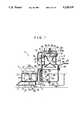
- FIG. 1whosw a side sectional view of the first embodiment of the this invention
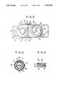
- FIG. 2shows a plan view of the first embodiment
- FIG. 3shows a plan view of the filter of the subseparator in the first embodiment
- FIG. 4shows a side sectional view of the filter.
- FIG. 5shows a side sectional view of a part of the filter
- FIG. 6shows a plan view of a part of the filter
- FIG. 7shows a side sectional view of the handle for securing the filter
- FIG. 8shows a side view of the pivoting rod for supporting the dirt receptacle in the first embodiment
- FIG. 9shows a plan vview of the pivoting rod
- FIG. 10shows a plan view of the dirt receptacle in the first embodiment
- FIG. 11shows a side view of the locking mechanism detachable securing the dirt receptacle
- FIG.12shkows a rear view of the locking mechanism
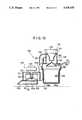
- FIG. 13shows a side sectional view of the second embodiment of the this invention.
- FIG. 14shows a plan view of the second embodiment
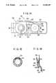
- FIG. 15shows a plan view of the filter of the subseparator in the second embodiment
- FIG. 16shows an enlarged sectional view of the locking mechanism of the dirt receptacle in the second embodiment
- FIG. 17shows a side sectional view of the third embodiment of this invention.
- FIG. 18shows a plan sectional view of the inlet in the third embodiment
- FIGS. 19 and 20show a plan sectional view of the modification of the inlet, respectively;
- FIG. 21shows a side sectional view of the fourth embodiment of this invention.
- FIG. 22shows a plan view of the fourth embodiment
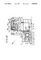
- FIG. 23shows a side sectional view of the fifth embodiment
- FIG. 24shows a perspective view of the fifth embodiment
- FIG. 25shows a side sectional view of the sixth embodiment of this invention.
- FIG. 26shows a plan view of the sixth embodiment of this invention.
- FIG. 27shows an side sectional view of the centrifugal dust separators of the sixth embodiment of this invention.
- FIG. 28shows a plan view of the the centrifugal dust separators
- FIG. 29shows a side sectional view of one of the centrifugal dust separators
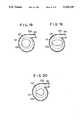
- FIG. 30shows a plan view of the fixed vanes of the the centrifugal dust separator.
- FIG. 31shows a perspective view of the fixed vanes.
- FIGS. 1 to 12show the first embodiment of this invention.
- the cleaning machine 1 of the this inventioncomprises a frame 2, a suction blower 3 mounted on the frame 2, an intake opening 4 communicating with the suction blower 3, a dirt separator 6 communicating with the suction blower 3 by means of a duct 5, and a dirt receptacle 9, which is detachably attached to the bottom of the dirt separator 6, for collecting the dirt separated in the dirt separator 6.
- the frame 2is provided with front wheels 21 and rear wheels 23 to make the frame 2 movable and a handle 25 for the operator which extends rearward from the frame 2.
- the blower 3is mounted on the front of the frame 2. This blower 3 incudes a housing 31 provided with an inlet 31a and an outlet 31b. An engine 33 is mounted on the top of the housing 31. A fan 37 is secured by a nut 39 on the crank shaft (rotating shaft) 35 of the engine 33, as is rotated about a horizontal axis horizontally by the engine 33.
- the intake opening 4is opened downward near the ground in front of the frame 2. This intake opening 4 communicates with the inlet 31a of the suction blower 3 through an intake duct 41 so as to suck dirt such as fallen leaves, dust and the like with the flow of air generated by roation of the fan 37 of the suction blower 3. The dirt thus sucked is sent out from the housing 31 through the outlet 31b together with the air.
- the outlet 31b of the suction blower 3communicates with the dirt separator 6 situated above the rear of the frame 2 by means of the duct 5.
- This dirt separatorcomprises a main separator 61 for separating relatively large dirt such as fallen leaves in the air and a subseparator 62 for separating relatively small dirt such as dust from the air discharged from the main separator.
- the main separator 61comprises a smaller-diameter cylindrical part 63 to which the duct 5 is connected, a larger-diameter cylindrical part 64 concentrically connected to the bottom of the smaller-diameter cylindrical part 63, and a funnel-shaped exhaust guide 65 which extends downward concentrically into the smaller-diameter cylindrical part from the top end.
- An outlet end 51 of the duct 5is connected to the upper part of the smaller-diameter cylindrical part 63 along tangential line so that the air from the suction blower 3 whirls along the innewr side of the smaller-diameter cylindrical part 63.
- the top end of the exhaust guide 65is bent upright into a cylindrical form and fixed to the top end of the smaller-diameter cylindrical part 63.
- a conical cover plate 66is disposed below the exhaust guide 65 with an appropriate spacing between its top end and the bottom end of the exhaust guide 65.
- the diameter of the bottom of the cover plate 66is greater than that of the bottom end of the exhaust guide 65.
- the bottom of the conical cover 66is held inside the the larger-diameter cylindrical part 64 with an appropriate spacing between its bottom and the inner side of the larger-diameter cylindrical part 64.
- the top-end of the conical cover 66extends into the smaller-diameter part 63.
- the subseparator 62is mounted on the top of the main separator 61 with the bottom end fitted in the cylindrical part of the exhaust guide 65.
- the subseparator 62comprises a cylindrical filter 70 roatably put on the top end of the exhaust guide 65.
- a ring packing 68is inserted between the filter unit 70 and the top end of the exhaust guide 65.
- the filter unit 70comprises a cylindrical filter made by forming a zigzag folded filter material into a ring shape as better as shown in FIGS. 3 to 6.
- the inner side and outer side of the filter 71are covered by cylindrical inner and outer side plates 72 and 73 with many holes.
- the top and bottom sides of the filter 71are covered by annular channel-section of top and bottom plates 74 and 75, respectively.
- the top end of the filter unit 70is held by a circular top cover 76 whose outer edge is bent downward.
- a handle 78is attached upright on the top cover 76, whose bottom end 77 protudes downward from the bottom side of the cover 76 into a hole 74a formed at an appropriate place in the top plate 74 of the filter unit 70 as clearly shown in FIG. 5.
- the ilter unit 70can be rotated on the exhaust guide 65 by gripping the handle 78 and rotating the top cover 67.
- a horizontal bracket 65ais trnasversely disposed inside the exhaust guide 65 as shown in FIGS. 1, 5 and 6. Each end of the bracket 65a is fixed on the inner side of the exhaust 65. Fixed upright at the middle point of the bracket 65a is a pin 80, which protrudes above the top cover 67 through a tubular member 81 attached to the center of the top cover 67. The upper part of the pin 80 is threaded and a handle 82 is screwed as shown in FIG. 7. A spring 85 is disposed between the bottom end of the handle 82 and a boss 83 fixed in the tubular member 81 around the pin 80. The top cover 76 is therefore pressed down to the filter unit 70 by the biasing force of the spring 85, and filter unit 70 is then urged against the packing 68.
- a resilient metal contact strap 79is attached to the outer surface of the top end of the exhaust guide 65 as better shownb in FIGS. 3 and 4.
- the contact strap 79is in contact with the outer side plate 73 of the filter unit 70 so as to discharge the static electricity built up in the filter 71 through the exhaust guitd 65, frame 2, and a ground chain 46 hung down from the intake duct 41.
- the duct 5is p rovided, above the opening 51 communicating with the smaller-diameter cylindrical part 63 of the main separator 61, with a blowing outlet 52 facing the outer side of the filter unit 70 for blowing the dust off the filter 71.
- Air flow in the duct 5is selectively directed to the opening 51 or the blowing outlet 52 by a valve 53 which is disposed in the duct 5 and turned by a lever 54.
- a cylindrical dirt receptacle 9 made of a material impermeable to airis attached to the bottom end of the larger-diameter cylindrical part 64 of the main separator 61 through a ring packing 90 disposed between as shown in FIG 1.
- the dirt receptacle 9is detachably secured to the bottom end of the larger-diameter cylindrical part 64 by the assistance of a pivoting rod 92 whose bottom end is mounted about a pivot shaft 91 on the frame 2 as better shown in the dotted lines in FIG. 1.
- the dirt receptacle 9is provided, at the blower-side of the top end, with a hooking member 9a protruding downwardly.
- the hooking member 9ais engageable with a V-shaped catch 93 at the top end of the pivoting rod 92.
- the pivoting rod 92is equipped at the middle with a turnbuckle 94 for adjusting the length of the pivoting rod 92 as better shown in FIG. 8. Further, the pivoting rod 92 is tied to the frame 2 by means of a chain 95 linked to the top end thereof so as to be pivotable between the first and the second positions.
- the pivoting rod 92supports the dirt receptacle 9 under the bottom end of the larger-diameter cylindrical part 64 at the first position as shown by the solid lines in FIG. 1 and allows the dirt receptacle 9 to land on the ground at the second position as shown by the dotted lines in FIG. 1
- the dirt receptacle 9is secured to the bottom end of the larger-diameter cylindrical part 64 by a locking mechanism 96 disposed at the rear side of the bottom end of the larger-diameter cylindrical part 64.
- the locking mechanism 96comprises a lever 97 whose bottom end is mounted about a pivot pin 97a supported by brackets 64b on the flange 64a of the larger-diameter cylindrical part 64 and a hook 98 whose top end is mounted about a pin 97b at the middle of the lever 97.
- the bottom end of the hook 96is so formed as to hook the bottom side of the flange 9c at the top end of the dirt receptacle 9. When the lever 97 is pushed up, the hook 96 pulls up the flange 9c and presses it against the packing 90.
- the dirt receptacle 9is equipped with a plurality of wheels 99 for making the receptacle 9 movable on the land, when it is detached from the bottom end of the larger-diameter cylindrical part 64.
- dirt and air from the intake openeing 4is blown into the smaller-diameter cylindrical part 63 of the main separator 61 through the outlet 31b of the suction blower 3, the duct 5, and the openi-ng 51 of the duct 5.
- the dirt thereinswirls with the air, and the large dirt moves toward the side wall of the main separator 61 by the centrifugal force, descends through the space between the conical cover 166 and the larger-diameter cylindrical part 64, and falls into the dirt receptacle 9.
- relatively small dirtsuch as dust enters the exhaust guide 65 and then the subseparator 62 by the air. There, the dust is caught by the filter unit 70.
- the operatorturns the lever 54 of the valve 53 and lets the air from the suction blower 3 blow out from the blowing outlet 52 against the filter unit 7. Then by loosening the handle 82 and turning the filter unit 70 by gripping the handle 78, the entire circumference of the filter unit 70 can be blown by the air. Thereby the dust clogged to the filter 71 is blown off and falls into the dirt receptacle 9.
- the operatorpulls down the lever 97 of the locking mechanism 96 rearward to unlock. While holding the flange 9c by hands, the operator unhooks the hook 96 from the flange 9c of the dirt receptacle 9 and pulls the dirt receptacle 9 rearward.
- the pivoting rod 82then turns from the first position to the second position and the dirt receptacle 9 is brought down on the ground. Since the dirt receptacle 9 is movable on wheels 99, the dirt collected in the dirt receptacle can easily be carried and discarded.
- the operatorTo attach the dirt receptacle 9, the operator first engages the hooking member 9a at the front side of the dirt receptacle 9 with the catch 93 at the top of the pivoting rod 92 held at the second position and then pushes the dirt receptacle 9 frontward by lifting the rear side thereof.
- the pivoting rod 92then turns frontward to the first position and presses the dirt receptacle 9 to the bottom end of the larger-diameter cylindrical part 64.
- the operatorWhile holding the dirt receptacle 9 at this position, the operator turns the lever 97 of the locking mechanism 96 to secure by the hook 96 the dirt receptacle 9 to the bottom end of the larger-diameter cylindrical part 64.
- the dirt receptacle 9can be easily attached and detached by the operator alone.
- this embodimentcan improve the efficiency of work and reduce the fatigue of the operator.
- the dirt receptacle 9may be square or any other form in section.
- pivoting rods or locking mechanismsmay be used.
- detaching the dirt receptaclecan be made easier by constructing the pivoting rod and the dirt receptacle so that when the hooking member is unhooked, the dirt receptacle can be turned with respect to the catch of the pivoting rod to the second position in such a manner that the dirt receptacle is supported on the wheels, and then pulled rearward. Further, attaching and detaching of the dirt receptacle be made much easier by the construction wherein the front and rear parts of the dirt receptacle are supported on two pivoting rods, respectively, and the dirt receptacle is lifted by the assistance of the two pivoting rods to the attached position by pushing it frontward.
- centrifugal dust separatormay be used for the subseparator instead of the filter as described above and a filter type separator may also used for the main separator instead of the centrifugal type separator as described above.
- FIGS. 13 to 15show the second embodiment of the this invention.
- the dirt receptacle detachably attached under the dirt separatoris so constructed that a dirt bag made of a material impermeable to air is additionally disposed inside and provided with air holes at the bottom of the dirt receptacle.
- collected dirtcan be easily taken out from the dirt receptacle by removing the dirt bag containing the dirt.
- the air between the receptacle and the bagflows through the air holes and the dirt bag is automatically filled out to fit the inner side of the dirt receptacle by a higher air pressure inside the machine.
- the dirt bagcan be set easily and quickly.
- reference numeral 100designates the cleaning machine of the second embodiment and 103 designates a suction blower.
- This cleaning machine 100is movable by front wheels 131 and rear wheels 132 and can be steered by the operator by means of a handle 125 disposed at the rear.
- the suction blower 103has a housing 131 provided with an inlet 131a and an outlet 131b. Mounted on the top of the housing 131 is an engine 133.
- the crank shaft (rotating shaft) 135 of the engine 133protrudes inside the housing 131 and a fan 137 is secured on the bottom end thereof by a nut 139.
- the fan 137is rotated about a horizontal axis by the engine 133.
- an intake opening 104Disposed below the suction blower 103 is an intake opening 104 which is opened downward close to the ground.
- This intake opening 104is communicated with the inlet 131a of the suction blower 103 through an intake duct 141 so as to suck dirt on the ground along with air by the sucking force generated by rotation of the fan 137 of the suction blower 103.
- the dirtis discharged from the housing 131 through the outlet 131b together with the air.
- the outlet 131b of the suction blower 103communicates with a dirt separator 106 situated behind the suction blower 103 by means of a duct 5.
- the dirt separator 106comprises a main separator 161 for separating relatively large dirt from the air and a subseparator 162 for separating relatively small dirt from the air which has passed through the main separator 161.
- the construction of the main separator 161is the same as in the first embodiment.
- the subseparator 161is mounted on the main separator 161 in the same way as in the first embodiment. That is, a cylindrical filter unit 170 is rotatably put in the cylindrical part at the top end of the exhaust guide 165.
- the filter unit 170comprises a cylindrical filter made by forming a zigzag folded filter material into a ring shape as shown in FIG. 15. The top side of the filter unit 170 is held by a top cover 176.
- a cylindrical dirt receptacle 109 made of a material impermeable to airis detachably attached to the bottom end of the larger-diameter cylindrical part 164 of the main separator 161 by means of clamps 180 oppositely disposed on the outer side of near the bottom end of the larger-diameter cylindrical part 164.
- the dirt receptacle 109is provided with a plurality of air holes 109a in the bottom.
- a dirt bag 190 made of a material impermeable to airis put in the dirt receptacle 109 with the top end held between the bottom end of the larger-diameter cylindrical part 164 and the top end of the dirt receptacle 109.
- Each clamp 180comprises a base plate 181 fixed on the outer side near the bottom end of the larger-diameter cylindrical part 164 and a lever 182 pivotably mounted on the base plate 181.
- the bottom end of the lever 182is formed into a hook 183.
- the lever 182is urged by a spring 185 in the direction in which the hook 183 engages with a hanging projection on the top end of the dirt receptacle 109.
- dirt sucked from the intake opening 104is blown into the main separator 161 through the outlet 131b of the suction blower 103 and the duct 105.
- the dirtswirls in the main separator 161 with the air, and the large dirt moves toward the side wall of the main separator 161 by the centrifugal force, falls through the space between the conical cover 166 and the larger-diameter cylindrical part 64, and is collected in the dirt bag 190.
- the operatortilts the cleaning machine 101 by pushing down the handle 125 until the bottom of the dirt receptacle 109 comes into contact with the ground, then releases the dirt receptacle 109 from the clamps 180 by pressing the lever 182.
- the operatorpulls up the handle 125, then the dirt receptacle 109 separates from the bottom end of the larger-diameter cylindrical part 164.
- the operatormoves the cleaning machine 1 forward, then the dirt receptacle 109 is left behind and the dirt bag 190 can be taken out.
- the air between the receptacle 109 and the bag 190flows out through the air holes 109a and the dirt bag 190 is automatically filled out to fit the inner side of the dirt receptacle 109 by a higher air pressure inside the machine. Further, even if there is a small hole in the bag and air leaks through the hole between the bag and the receptacle, the air is expelled through the air holes 109a without causing the bag to swell inward off the receptacle 109, flutter out of the receptacle, or block the exhaust passage. In addition, since water flows out from the air holes 109a, washing of the dirt receptacle 109 is made easier.
- FIGS. 17 to 20show the third embodiment of the this invention.
- the inlet of the suction blower in the housingis formed into a circular shape concentric with the axis of rotation of the fan.
- the shape of the inletis deformed from the circular shape as described above to the shape in which a can caught between the inner edge of the housing defining the inlet and the fun is automatically disengaged therefrom during the revolution of the fan.
- the inner edge of the housingis so formed as to have at least a part against which the caught can is hit during the revolution of the can along with the fan, causing the can to drop down into the intake duct or to be drawn again through the inlet.
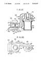
- FIG. 17shows a side sectional view of the cleaning machine 100 of this embodiment.
- the constructionis the same as that in FIG. 13 except that the dirt receptacle 109 has no air holes.
- FIG. 18shows a sectional view of the suction blower 103 of this embodiment.
- the suction blower 103communicates with a dirt intake 104 which is disposed below the suction blower 103 and opens close to the ground through an inlet 131a formed in the housing 131 and an intake duct 141.
- the inlet 131ahas an eccentric circular shape whose center is deviated from the axis of rotation shaft 135 of the fan 137 so as to have an extended part as shown in FIG. 18.
- a canif a can is sucked in and caught between the inner edge of the housing 131 defining the inlet 131a and the fan 137 without passing through the fan, it revolves along with the fan 137 and hits against the inner edge of the housing forming the extended part of the inlet 131a during the revolution of the fan, dislodging the can, which then falls down into the intake duct 141 or is sucked again through the inlet 131a.
- FIG. 19shows a modification of this embodiment.
- the shape of the inlet 131a of this modificationhas an elliptical shape symmetric with respect to the axis of the fan 137.
- the two opposite parts of the ellipse shape inletare extended to near the circumference of the fan 137.
- FIG. 20shows another modification of this embodiment.
- the inlet 131a of this modificationis formed into such a shape that a part of the circumference of a circle centered at the axis of the fan 137 is extended outward to near the circumference of the fan 137.
- FIGS. 21 and 22show the fourth embodiment of the this invention.
- This embodimentis characterized in the construction of the dirt separator. That is, in this dirt separator, a duct communicating with the outlet of the suction blower is connected to a cylindrical part of the main separator along a tangential line thereof, a cylindrical exhaust guide provided with a subseparator thereon is disposed concentrically inside the upper part of the cylindrical part, and a circular cover plate is disposed under the subseparator.
- the cleaning machine 200 of this embodimenthas a suction blower 203 having an housing 231 with an inlet 231a.
- An engine 233is mounted on the housing 231 of the suction blower 203.
- the crank shaft 235 of the engine 233protrudes downward inside the housing 231.
- a fan 237is secured by a nut 239 on the crank shaft 235 and rotates horizontally by the engine 233.
- An intake opening 204is opened downward close to the ground below the suction blower 203.
- the intake opening 204is communicated with the inside of the housing 231 through an intake duct 241 and the inlet 231a of the housing 231.
- the housing 231is provided at the rear part thereof with an outlet 231b for blowing out dirt along with air.
- the outlet 231bcommunicates with a dust separator 206 situated behind the suction blower 203 through a duct 205.
- a dust separator 206situated behind the suction blower 203 through a duct 205.
- front wheels 222 and rear wheels 224Disposed below the suction blower 203 are front wheels 222 and rear wheels 224.
- the dirt separator 206comprises a main separator 261 for separating relatively large dirt from the air and a subseparator 262 for catching dust in the air.
- the main separator 261comprises a smaller-diameter cylindrical part 263 and a larger-diameter cylindrical part 264 connected to the bottom of the smaller-diameter cylindrical part 263.
- Connected to the smaller-diameter part 263is the duct 205 so that the air from the suction blower 203 flows into the smaller-diameter cylindrical part 263 along a tangential line thereof.
- a cylindrical exhaust guide 265is disposed concentrically.
- the subseparator 262is attached at the bottom end of the exhaust guide 265.
- the subseparator 265is wire mesh formed into a cylinder having substantially the same diameter of the exhaust guide 265.
- a circular cover plate 266is disposed below the subseparator 262 at about the middle of the larger-diameter cylindrical part 264 with an appropriate space between the circumference thereof and the inner side of the larger-diameter cylindrical part 264.
- the cover plate 266prevents the dirt collected in a dirt receptacle 208 below from flying up and being pressed over the outer surface of the subseparator 262.
- the dirt receptacle 208 made of wire meshis detachably secured to the bottom end of the larger-diameter cylindrical part 264 by means of clamps 209.
- a dirt bagis set in the dirt receptacle 208 with the top end pressed between the bottom end of the larger-diameter cylindrical part 263 and a sealing means such as rubber or sponge affixed to the inner side of the top end of the dirt receptacle 2083.
- dirt sucked together with air from the intake opening 204 by the suction blower 203is discharged from the outlet 231b of the housing 231 along with the air, passes through the duct 205, and enters the smaller-diameter cylindrical part 263 of the main separator 261 in a tangential direction thereof.
- the dirt thereinrotates with the air and while rotating it moves toward the sidewall of the smaller-diameter cylindrical part 263.
- relatively large dirtsuch as fallen leaves and pieces of waste paper falls through the space around the cover plate 266 and into the dirt receptacle 208, while small dust is separated from the air by the wire mesh of the subseparator 262 when the air flows into the exhaust guide 265.
- the substantially dust-free airis disharged outside from the top end of the exhaust guide 265.
- the collected dirtcan be easily taken out and discarded in a bag; the dirt receptacle is light and easy to handle; and the dirt bag is automatically filled out to fit the inner side of the dirt receptacle by a higher air pressure inside the machine.
- the exhaust guide 265may be formed into the shape of a funnel.
- the subseparator 262may be a filter made of a filter material other than wire mesh or a centrifugal separator.
- the subseparatormay also be disposed above the exhaust guide 265.
- the dirt receptaclemay be made of a material impermeable to air such as plastics.
- FIGS. 23 and 24show the fifth embodiment of the this invention.
- a pulleyis mounted to the crank shaft.
- a endless beltfor transmitting a driving force of the engine to a rotating brush disposed in front of the dirt intake opening or to the wheels of the machine.
- the cleaning machine 300 of this embodimentis provided with a suction blower 303.
- the suction blower 303comprises a housing 331, an engine 333 and a fan 337.
- the engine 333is mounted on the housing 331.
- the crank shaft 335 of the engine 333protrudes downward inside the housing 331.
- a pulley 334is mounted to the base of the crank shaft 335.
- the fan 337is mounted to the bottom end of the crank shaft 335 and secured by means of a nut 339.
- Disposed below the suction blower 303are front wheels 321 and rear wheels 323 for making the machine movable.
- a handle 325 for steering the machineis extended rearward from the rear part of the suction blower 303.
- a dirt intake 304Disposed below the suction blower 303 is a dirt intake 304, which is opened downward close to the ground.
- the dirt intake 304is communicated with the housing 331 through an inlet 331a in the bottom side of the housing 331.
- an outlet 331bProvided at the rear part of the housing 331 is an outlet 331b.
- a duct 305Connected to the outlet 331b is a duct 305, which is then connected to a dirt separator 306 and a dirt receptacle (not shown) behind the suction blower 303.
- a rotary brush 350is horizontally supported by a pair of bracket plats 347 so as to be in contact with the ground.
- a pulley 353is secured on one end of the shaft 351 of the rotary brush 350.
- Two idle pulleys 355are mounted on the front part of the housing 331 of the suction blower 303.
- a endless flexible belt 358is passed about the pulley 334 on the crank shaft 335 on the engine and the pulley 353 of the shaft 351 of the rotary brush 350 and guided by the idle pulleys 355 on the housing 331.
- the operatorstarts the engine 333 and steers the machine gripping the handle 325.
- the fan 337 of the suction blower 303rotates and generates a powerful sucking force. Dirt such as fallen leaves and dust is sucked by this sucking force from the dirt intake 304 together with air, blown into the dirt separator 306, and there separated from the air and collected in the dirt receptacle.
- Rotation of the engine 33is also transmitted to the rotary brush 350 by means of the belt 358, and the rotary brush 350 rotates.
- the rotary brush 350gathers and stirs up dirt and dust toward the dirt intake 304, which increases the cleaning ability.
- the rotary brushmay be so disposed as to rotate around a vertical rotating shaft.
- the belt 358may also be used to drive wheels.
- FIGS. 25 to 31show the sixth embodiment of this invention.
- the cleaning machine 400 of this embodimentdiffers from the first embodiment by the type of the dust separator used for the subseparator, which in this embodiment is a centrifugal type dust separator removing relatively small dirt such as dust by a centrifugal force.
- the other constructionis almost the same as that of the first embodiment. Then the same components are designated with the same reference numerals as in the description of the first embodiment, by doing so the detailed description of those components are omitted.
- a first subseparator 462is disposed above the main separator 61.
- the first subseparator 462includes a cylindrical separating chamber 467.
- This separating chamber 467is partitioned into a upper chamber 467a and a lower room 467b by a bottom plate 468 with a plurality of holes 468a formed therein.
- the top end of this separating chamber 467is defined by a top plate 469.
- centrifugal dust separator 470Situated in the upper chamber 467a of the separating chamber 467 are a plurality of centrifugal dust separators 470.
- Each of the centrifugal dust separator 470includes a cylindrical outer guide 471 extending upwardly from the bottom plate 468 as shown in the FIGS. 29 to 31.
- the bottom end of the outer guide 471encloses one of the holes 468a in the bottom plate and communicates with the exhaust guide 65 through the hole in FIGS. 29 to 31.
- the top end of the outer guide 471is open in the upper chamber 467a.
- the bottom end of a funnel-shaped inner guide 472is disposed within the upper part of the outer guide 471, forming an annular space 473 therebetween.
- the top end of the inner guide 472encloses one of the holes 469a formed in the top plate 469 right above each outer guide 471.
- a swirl vane 474which has four radial vane member 474 slanted with respect to the centrifugal direction is disposed in the bottom end of the outer guide 471. The air which flows into each centrifugal dust separator 470 is rotated as it passes through the swirl vane 474.
- the second subseparator 480is partially disposed in the separating chamber 467 of the first subseparator 462 as better shown in FIG. 27.
- the second subseparator 400includes a cylindrical separating chamber 480.
- the separating chamber 480is defined by the cylindrical side wall, a bottom plate 483 with a plurality of holes 483a formed therein, a partition plate 484 which divides the chamber 480 into an upper chamber 485 and a lower room 486, and a top plate 487.
- the bottom plate 483is elevated at an appropriate height from the bottom plate 468 of the first subseparator 462 so that the first side stream, which is the dust-laden air stream discharged from the first centrifugal separators 470 into the upper room 467a of the first subseparator 62 the centrifugal separators 470, small dirt such as dust separated by the centrifugal separator 470, enters the second subseparator 480 through the holes 483a in the bottom plate 483.
- each second centrifugal dust separator 470'Disposed in the lower chamber 486 are a plurality of second centrifugal dust separators 470'.
- the construction of the each second centrifugal dust separators 470'is the same as that of the first centrifugal dust separators 470. That is, each of the second centrifugal dust separator 470' has a cylindrical outer guide 471' extending upwardly from the bottom plate 483.
- the bottom end of the outer guide 471'encloses one of the holes 483a in the bottom plate 483 and communicates with the upper chamber 467a of the first subseparator 62 as shown in FIGS. 29 to 31.
- the top end of the outer guide 471'is open in the lower room 486.
- a funnel-shaped inner guide 472'is disposed within the upper part of the outer guide 471', forming an annular space 473' therebetween.
- the top end of the inner guide 472'encloses one of the holes 484a formed in the partition plate 484 right above each outer guide 471' and communicates with the upper room 485.
- a swirl vane 474'which has four radial vane members 474a' slanted with respect to the centrifugal direction is disposed in the bottom end of the outer guide 471' in such a manner that the air which enters the outer guide 471' is rotated as it passes through the swirl vane 474'.
- a dust discharging duct 490is connected to the lower chamber 486.
- the other end of the dust discharge duct 490is opened downward close to the ground.
- An exhaust duct 411is connected to the upper chamber 485.
- the other end of the exhaust duct 411opens into the hood 475 near the outlet 476 obliquely to the direction in which the air flows out.
- each centrifugal dust separator 470through the hole 468a is rotated as it flows upward through the swirl vane 474.
- the dust in the airmoves toward the side wall of the outer guide 471 by centrifugal force, and then flows upward through annular space 473 into upper chamber 467a as the first side flow.
- the substantially dust-free airflows out into the inner guide 472, and constitutes the first main flow. This main stream then flows outside from the outlet 476 of the hood 475.
- the first side flowthen enters the centrifugal dust separators 470' of the second subseparator 480 and is further separated into the dust-laden second side flow and the substantially dust-free second main flow.
- the second side flowenters the lower room 486 and is discharged through the dust discharging duct 490.
- the second main flowenters the upper chamber 485, flows out from the upper chamber 485 through the exhaust duct 411 into the hood 485 with the assistance of a decreased pressure caused by the first main flow in the hood 475.
- the combined first and second main flowsare then discharged through outlet 476.
- the second subseparatormay be disposed separately from the first subseparator by connecting them with an appropriate conduit, or may be omitted.
- first subseparatorcan be employed in this embodiment without providing the second subseparator.
Landscapes
- Chemical & Material Sciences (AREA)
- Chemical Kinetics & Catalysis (AREA)
- Engineering & Computer Science (AREA)
- Mechanical Engineering (AREA)
- Architecture (AREA)
- Civil Engineering (AREA)
- Structural Engineering (AREA)
- Filters For Electric Vacuum Cleaners (AREA)
Abstract
Description
1. Field of the Invention
The this invention relates to a cleaning machine. In particular, the invention relates to a cleaning machine which comprises a suction blower driven by an engine, a dirt intake communicated with the inlet of the suction blower, a dirt separator communicated with the outlet of the suction blower by means of a duct, and a dirt receptacle disposed under the dirt separator. The cleaning machine sucks dirt on the ground together with air by a powerful sucking force generated by rotation of the suction blower driven by the engine and collects the dirt into the dirt receptacle.
2. Description of the Prior Art
One of known cleaning machines of this type sucks various dirt such as fallen leaves and small powdered earth on the ground together with air by a powerful sucking force generated by a suction blower, separates the dirt from the air by a dirt separator, and collects the separated dirt into an air-permeable dirt bag attached under the dirt separator. Dust such as small powdered earth is prone to clog in the mesh of the dirt bag to increase the resistance to passage of air, thus causing decrease of the sucking power. Further, fine dust clogged in the mesh flies up when taking out the bag and discarding the dirt therein. Furthermore, since a large amount of dirt is collected in a cleaning work by this type of cleaning machines, the dirt bag which is full of the dirt is very heavy and difficult to handle.
It is therefor an major object of the present invention to provide a cleaning machine with which collected dirt can be easily discarded without dispersing fine dust.
Another object of the present invention is to provide a cleaning machine in which the dirt receptacle full of collected dirt can be easily detached and handled.
To attain the above objects, the cleaning machine of the present invention comprises a suction blower having an inlet and an outlet; an intake opening communication with the inlet of the suction blower; a main separator for separating relatively large dirt such as fallen leaves; a subseparator for separating relatively small dirt such as dust from the air diescharged from the main separator; and a dirt receptacle made of an air-impermeable material detachable attached under the main separator.
According to the cleaning machine of the present invention as constructed above, the relatively large dirt is first separated by teh amin separator and collected into the dirt receptacle. The dust-laden air discharged from the main separator is forced to flow into the subseparator because it can not flow out through the dirt receptacle made of the air-impermeable material. In the subseparator the small dirt is removed from the air, and the air is discharged outside. In this construction, only the relatively large dirt such as fallen leaves and pieces of waste paper is collected into the dirt receptacle detachably attached under the main separator. Moreoer, the dirt receptacle is made of an air-impermeable material and has no mesh into which dust is liable to clog. The dirt can then be easily discarede from the receptacle without dispersing the fine dust.
Further, the cleaning machine of the this invention may be so constructed that one side of the top end of the dirt receptacle is put on a pivoting rod and the opposite side is secured to the bottom end of said main separator by a locking mechanism. According to this construction, the dirt receptacle can be easily attached and detached by the operator without any assistance. Thereby the efficiency of work is imiproved and the fatigue of the operator is reduced.
Further, the dirt receptacle may be provided with wheel on the bottom so that the dirt receptacle can be easily moved after being detached from the machine.
Further, the dirt receptacle and the locking mechanism of the dirt receptacle may be constructed so that a dirt bag made of an air-impermeable material can be additionally held within the dirt receptracle. According to this construction, the collected dirt can be very easily taken out from the dirt receptacle and discarded.
Furthermore, the dirt receptacle may be provided with air holes in the bottom. If so, the dirt bag is automatically filled out to fit the inner side of the dirt receptacle by the assistance of a higher air pressure inside the machine. In addition, since water flows out from the air holes, washing of the dirt receptacle is made easier.
The other objects, constructions, and advantages of this invention will become apparent from the detailed description of the preferred embodiments of this invention below.
FIG. 1 whosw a side sectional view of the first embodiment of the this invention;
FIG. 2 shows a plan view of the first embodiment;
FIG. 3 shows a plan view of the filter of the subseparator in the first embodiment;
FIG. 4 shows a side sectional view of the filter.
FIG. 5 shows a side sectional view of a part of the filter;
FIG. 6 shows a plan view of a part of the filter;
FIG. 7 shows a side sectional view of the handle for securing the filter;
FIG. 8 shows a side view of the pivoting rod for supporting the dirt receptacle in the first embodiment;
FIG. 9 shows a plan vview of the pivoting rod;
FIG. 10 shows a plan view of the dirt receptacle in the first embodiment;
FIG. 11 shows a side view of the locking mechanism detachable securing the dirt receptacle;
FIG.12 shkows a rear view of the locking mechanism;
FIG. 13 shows a side sectional view of the second embodiment of the this invention;
FIG. 14 shows a plan view of the second embodiment;
FIG. 15 shows a plan view of the filter of the subseparator in the second embodiment;
FIG. 16 shows an enlarged sectional view of the locking mechanism of the dirt receptacle in the second embodiment;
FIG. 17 shows a side sectional view of the third embodiment of this invention;
FIG. 18 shows a plan sectional view of the inlet in the third embodiment;
FIGS. 19 and 20 show a plan sectional view of the modification of the inlet, respectively;
FIG. 21 shows a side sectional view of the fourth embodiment of this invention;
FIG. 22 shows a plan view of the fourth embodiment;
FIG. 23 shows a side sectional view of the fifth embodiment;
FIG. 24 shows a perspective view of the fifth embodiment;
FIG. 25 shows a side sectional view of the sixth embodiment of this invention;
FIG. 26 shows a plan view of the sixth embodiment of this invention;
FIG. 27 shows an side sectional view of the centrifugal dust separators of the sixth embodiment of this invention;
FIG. 28 shows a plan view of the the centrifugal dust separators;
FIG. 29 shows a side sectional view of one of the centrifugal dust separators;
FIG. 30 shows a plan view of the fixed vanes of the the centrifugal dust separator; and
FIG. 31 shows a perspective view of the fixed vanes.
The embodiments of this invention will be described below in detail with reference to the accompanying drawings.
FIGS. 1 to 12 show the first embodiment of this invention. As shown better in FIGS. 1 and 2, the cleaning machine 1 of the this invention comprises aframe 2, asuction blower 3 mounted on theframe 2, anintake opening 4 communicating with thesuction blower 3, adirt separator 6 communicating with thesuction blower 3 by means of aduct 5, and adirt receptacle 9, which is detachably attached to the bottom of thedirt separator 6, for collecting the dirt separated in thedirt separator 6.
Theframe 2 is provided withfront wheels 21 andrear wheels 23 to make theframe 2 movable and ahandle 25 for the operator which extends rearward from theframe 2.
Theblower 3 is mounted on the front of theframe 2. Thisblower 3 incudes ahousing 31 provided with aninlet 31a and anoutlet 31b. Anengine 33 is mounted on the top of thehousing 31. Afan 37 is secured by anut 39 on the crank shaft (rotating shaft) 35 of theengine 33, as is rotated about a horizontal axis horizontally by theengine 33.
Theintake opening 4 is opened downward near the ground in front of theframe 2. Thisintake opening 4 communicates with theinlet 31a of thesuction blower 3 through anintake duct 41 so as to suck dirt such as fallen leaves, dust and the like with the flow of air generated by roation of thefan 37 of thesuction blower 3. The dirt thus sucked is sent out from thehousing 31 through theoutlet 31b together with the air.
Theoutlet 31b of thesuction blower 3 communicates with thedirt separator 6 situated above the rear of theframe 2 by means of theduct 5. This dirt separator comprises amain separator 61 for separating relatively large dirt such as fallen leaves in the air and asubseparator 62 for separating relatively small dirt such as dust from the air discharged from the main separator.
Themain separator 61 comprises a smaller-diametercylindrical part 63 to which theduct 5 is connected, a larger-diametercylindrical part 64 concentrically connected to the bottom of the smaller-diametercylindrical part 63, and a funnel-shapedexhaust guide 65 which extends downward concentrically into the smaller-diameter cylindrical part from the top end. An outlet end 51 of theduct 5 is connected to the upper part of the smaller-diametercylindrical part 63 along tangential line so that the air from thesuction blower 3 whirls along the innewr side of the smaller-diametercylindrical part 63. The top end of theexhaust guide 65 is bent upright into a cylindrical form and fixed to the top end of the smaller-diametercylindrical part 63. Aconical cover plate 66 is disposed below theexhaust guide 65 with an appropriate spacing between its top end and the bottom end of theexhaust guide 65. The diameter of the bottom of thecover plate 66 is greater than that of the bottom end of theexhaust guide 65. The bottom of theconical cover 66 is held inside the the larger-diametercylindrical part 64 with an appropriate spacing between its bottom and the inner side of the larger-diametercylindrical part 64. The top-end of theconical cover 66 extends into the smaller-diameter part 63.
Thesubseparator 62 is mounted on the top of themain separator 61 with the bottom end fitted in the cylindrical part of theexhaust guide 65. Thesubseparator 62 comprises acylindrical filter 70 roatably put on the top end of theexhaust guide 65. A ring packing 68 is inserted between thefilter unit 70 and the top end of theexhaust guide 65.
Thefilter unit 70 comprises a cylindrical filter made by forming a zigzag folded filter material into a ring shape as better as shown in FIGS. 3 to 6. The inner side and outer side of thefilter 71 are covered by cylindrical inner andouter side plates filter 71 are covered by annular channel-section of top andbottom plates filter unit 70 is held by a circulartop cover 76 whose outer edge is bent downward. Ahandle 78 is attached upright on thetop cover 76, whosebottom end 77 protudes downward from the bottom side of thecover 76 into ahole 74a formed at an appropriate place in thetop plate 74 of thefilter unit 70 as clearly shown in FIG. 5. Theilter unit 70 can be rotated on theexhaust guide 65 by gripping thehandle 78 and rotating the top cover 67.
Ahorizontal bracket 65a is trnasversely disposed inside theexhaust guide 65 as shown in FIGS. 1, 5 and 6. Each end of thebracket 65a is fixed on the inner side of theexhaust 65. Fixed upright at the middle point of thebracket 65a is apin 80, which protrudes above the top cover 67 through atubular member 81 attached to the center of the top cover 67. The upper part of thepin 80 is threaded and ahandle 82 is screwed as shown in FIG. 7. Aspring 85 is disposed between the bottom end of thehandle 82 and aboss 83 fixed in thetubular member 81 around thepin 80. Thetop cover 76 is therefore pressed down to thefilter unit 70 by the biasing force of thespring 85, andfilter unit 70 is then urged against the packing 68.
A resilientmetal contact strap 79 is attached to the outer surface of the top end of theexhaust guide 65 as better shownb in FIGS. 3 and 4. Thecontact strap 79 is in contact with theouter side plate 73 of thefilter unit 70 so as to discharge the static electricity built up in thefilter 71 through theexhaust guitd 65,frame 2, and aground chain 46 hung down from theintake duct 41.
Theduct 5 is p rovided, above theopening 51 communicating with the smaller-diametercylindrical part 63 of themain separator 61, with a blowingoutlet 52 facing the outer side of thefilter unit 70 for blowing the dust off thefilter 71. Air flow in theduct 5 is selectively directed to theopening 51 or the blowingoutlet 52 by avalve 53 which is disposed in theduct 5 and turned by alever 54.
Acylindrical dirt receptacle 9 made of a material impermeable to air is attached to the bottom end of the larger-diametercylindrical part 64 of themain separator 61 through a ring packing 90 disposed between as shown in FIG 1. Thedirt receptacle 9 is detachably secured to the bottom end of the larger-diametercylindrical part 64 by the assistance of a pivotingrod 92 whose bottom end is mounted about apivot shaft 91 on theframe 2 as better shown in the dotted lines in FIG. 1.
That is, thedirt receptacle 9 is provided, at the blower-side of the top end, with a hookingmember 9a protruding downwardly. The hookingmember 9a is engageable with a V-shapedcatch 93 at the top end of the pivotingrod 92. The pivotingrod 92 is equipped at the middle with aturnbuckle 94 for adjusting the length of the pivotingrod 92 as better shown in FIG. 8. Further, the pivotingrod 92 is tied to theframe 2 by means of achain 95 linked to the top end thereof so as to be pivotable between the first and the second positions. Namely, the pivotingrod 92 supports thedirt receptacle 9 under the bottom end of the larger-diametercylindrical part 64 at the first position as shown by the solid lines in FIG. 1 and allows thedirt receptacle 9 to land on the ground at the second position as shown by the dotted lines in FIG. 1
Thedirt receptacle 9 is secured to the bottom end of the larger-diametercylindrical part 64 by alocking mechanism 96 disposed at the rear side of the bottom end of the larger-diametercylindrical part 64. Thelocking mechanism 96 comprises alever 97 whose bottom end is mounted about apivot pin 97a supported bybrackets 64b on the flange 64a of the larger-diametercylindrical part 64 and ahook 98 whose top end is mounted about apin 97b at the middle of thelever 97. The bottom end of thehook 96 is so formed as to hook the bottom side of theflange 9c at the top end of thedirt receptacle 9. When thelever 97 is pushed up, thehook 96 pulls up theflange 9c and presses it against the packing 90.
Further, thedirt receptacle 9 is equipped with a plurality ofwheels 99 for making thereceptacle 9 movable on the land, when it is detached from the bottom end of the larger-diametercylindrical part 64.
In the above embodiment, dirt and air from theintake openeing 4 is blown into the smaller-diametercylindrical part 63 of themain separator 61 through theoutlet 31b of thesuction blower 3, theduct 5, and the openi-ng 51 of theduct 5. The dirt therein swirls with the air, and the large dirt moves toward the side wall of themain separator 61 by the centrifugal force, descends through the space between theconical cover 166 and the larger-diametercylindrical part 64, and falls into thedirt receptacle 9. On the other hand, relatively small dirt such as dust enters theexhaust guide 65 and then thesubseparator 62 by the air. There, the dust is caught by thefilter unit 70.
When thefilter 71 is clogged with the dust, the operator turns thelever 54 of thevalve 53 and lets the air from thesuction blower 3 blow out from the blowingoutlet 52 against thefilter unit 7. Then by loosening thehandle 82 and turning thefilter unit 70 by gripping thehandle 78, the entire circumference of thefilter unit 70 can be blown by the air. Thereby the dust clogged to thefilter 71 is blown off and falls into thedirt receptacle 9.
To take out the dirt tus collected in thedirt receptacle 9, the operator pulls down thelever 97 of thelocking mechanism 96 rearward to unlock. While holding theflange 9c by hands, the operator unhooks thehook 96 from theflange 9c of thedirt receptacle 9 and pulls thedirt receptacle 9 rearward. The pivotingrod 82 then turns from the first position to the second position and thedirt receptacle 9 is brought down on the ground. Since thedirt receptacle 9 is movable onwheels 99, the dirt collected in the dirt receptacle can easily be carried and discarded.
To attach thedirt receptacle 9, the operator first engages the hookingmember 9a at the front side of thedirt receptacle 9 with thecatch 93 at the top of the pivotingrod 92 held at the second position and then pushes thedirt receptacle 9 frontward by lifting the rear side thereof. The pivotingrod 92 then turns frontward to the first position and presses thedirt receptacle 9 to the bottom end of the larger-diametercylindrical part 64. While holding thedirt receptacle 9 at this position, the operator turns thelever 97 of thelocking mechanism 96 to secure by thehook 96 thedirt receptacle 9 to the bottom end of the larger-diametercylindrical part 64.
In this embodiment, thedirt receptacle 9 can be easily attached and detached by the operator alone. Thus this embodiment can improve the efficiency of work and reduce the fatigue of the operator.
Further, in this embodiment, thedirt receptacle 9 but may be square or any other form in section.
Furthermore, two or more pivoting rods or locking mechanisms may be used.
Moreover, detaching the dirt receptacle can be made easier by constructing the pivoting rod and the dirt receptacle so that when the hooking member is unhooked, the dirt receptacle can be turned with respect to the catch of the pivoting rod to the second position in such a manner that the dirt receptacle is supported on the wheels, and then pulled rearward. Further, attaching and detaching of the dirt receptacle be made much easier by the construction wherein the front and rear parts of the dirt receptacle are supported on two pivoting rods, respectively, and the dirt receptacle is lifted by the assistance of the two pivoting rods to the attached position by pushing it frontward.
Further, a centrifugal dust separator may be used for the subseparator instead of the filter as described above and a filter type separator may also used for the main separator instead of the centrifugal type separator as described above.
FIGS. 13 to 15 show the second embodiment of the this invention. In this embodiment, the dirt receptacle detachably attached under the dirt separator is so constructed that a dirt bag made of a material impermeable to air is additionally disposed inside and provided with air holes at the bottom of the dirt receptacle. According to this embodiment, collected dirt can be easily taken out from the dirt receptacle by removing the dirt bag containing the dirt. Further, when having attached the dirt receptacle with a new dirt bag to be put in and starting the engine, the air between the receptacle and the bag flows through the air holes and the dirt bag is automatically filled out to fit the inner side of the dirt receptacle by a higher air pressure inside the machine. Thus the dirt bag can be set easily and quickly. The detailed description of this embodiment is as follows.
In FIGS. 13 to 15,reference numeral 100 designates the cleaning machine of the second embodiment and 103 designates a suction blower. Thiscleaning machine 100 is movable byfront wheels 131 and rear wheels 132 and can be steered by the operator by means of ahandle 125 disposed at the rear.
The construction of thesuction blower 103 is the same as in the first embodiment. That is, thesuction blower 103 has ahousing 131 provided with aninlet 131a and anoutlet 131b. Mounted on the top of thehousing 131 is anengine 133. The crank shaft (rotating shaft) 135 of theengine 133 protrudes inside thehousing 131 and afan 137 is secured on the bottom end thereof by anut 139. Thefan 137 is rotated about a horizontal axis by theengine 133.
Disposed below thesuction blower 103 is anintake opening 104 which is opened downward close to the ground. Thisintake opening 104 is communicated with theinlet 131a of thesuction blower 103 through anintake duct 141 so as to suck dirt on the ground along with air by the sucking force generated by rotation of thefan 137 of thesuction blower 103. The dirt is discharged from thehousing 131 through theoutlet 131b together with the air.
Theoutlet 131b of thesuction blower 103 communicates with adirt separator 106 situated behind thesuction blower 103 by means of aduct 5. Thedirt separator 106 comprises amain separator 161 for separating relatively large dirt from the air and a subseparator 162 for separating relatively small dirt from the air which has passed through themain separator 161.
The construction of themain separator 161 is the same as in the first embodiment. Thesubseparator 161 is mounted on themain separator 161 in the same way as in the first embodiment. That is, acylindrical filter unit 170 is rotatably put in the cylindrical part at the top end of theexhaust guide 165.
Thefilter unit 170 comprises a cylindrical filter made by forming a zigzag folded filter material into a ring shape as shown in FIG. 15. The top side of thefilter unit 170 is held by atop cover 176.
Acylindrical dirt receptacle 109 made of a material impermeable to air is detachably attached to the bottom end of the larger-diametercylindrical part 164 of themain separator 161 by means ofclamps 180 oppositely disposed on the outer side of near the bottom end of the larger-diametercylindrical part 164. Thedirt receptacle 109 is provided with a plurality ofair holes 109a in the bottom. Adirt bag 190 made of a material impermeable to air is put in thedirt receptacle 109 with the top end held between the bottom end of the larger-diametercylindrical part 164 and the top end of thedirt receptacle 109.
Eachclamp 180 comprises abase plate 181 fixed on the outer side near the bottom end of the larger-diametercylindrical part 164 and alever 182 pivotably mounted on thebase plate 181. The bottom end of thelever 182 is formed into ahook 183. Thelever 182 is urged by aspring 185 in the direction in which thehook 183 engages with a hanging projection on the top end of thedirt receptacle 109.
In the above embodiment, dirt sucked from theintake opening 104 is blown into themain separator 161 through theoutlet 131b of thesuction blower 103 and theduct 105. The dirt swirls in themain separator 161 with the air, and the large dirt moves toward the side wall of themain separator 161 by the centrifugal force, falls through the space between theconical cover 166 and the larger-diametercylindrical part 64, and is collected in thedirt bag 190.
To take out the dirt in thedirt receptacle 109, the operator tilts the cleaning machine 101 by pushing down thehandle 125 until the bottom of thedirt receptacle 109 comes into contact with the ground, then releases thedirt receptacle 109 from theclamps 180 by pressing thelever 182. Next the operator pulls up thehandle 125, then thedirt receptacle 109 separates from the bottom end of the larger-diametercylindrical part 164. Finally the operator moves the cleaning machine 1 forward, then thedirt receptacle 109 is left behind and thedirt bag 190 can be taken out.
After having attached thedirt receptacle 109 with anew dirt bag 190 and starting theengine 133, the air between thereceptacle 109 and thebag 190 flows out through theair holes 109a and thedirt bag 190 is automatically filled out to fit the inner side of thedirt receptacle 109 by a higher air pressure inside the machine. Further, even if there is a small hole in the bag and air leaks through the hole between the bag and the receptacle, the air is expelled through theair holes 109a without causing the bag to swell inward off thereceptacle 109, flutter out of the receptacle, or block the exhaust passage. In addition, since water flows out from theair holes 109a, washing of thedirt receptacle 109 is made easier.
FIGS. 17 to 20 show the third embodiment of the this invention. In the first and second embodiments described above, the inlet of the suction blower in the housing is formed into a circular shape concentric with the axis of rotation of the fan. With this construction, a discarded can sucked in is sometimes caught between the part of the housing around the inlet and the fan and revolves around the air intake along with the fan, which damages the blades of the fan or causes a malfunction by overloading.
In this embodiment, the shape of the inlet is deformed from the circular shape as described above to the shape in which a can caught between the inner edge of the housing defining the inlet and the fun is automatically disengaged therefrom during the revolution of the fan. Specifically, the inner edge of the housing is so formed as to have at least a part against which the caught can is hit during the revolution of the can along with the fan, causing the can to drop down into the intake duct or to be drawn again through the inlet.
The other construction of this embodiment is substantially the same as that of the second embodiment. Therefore, the same components are designated the same reference numerals as in the second embodiment and the detailed description of them is omitted.
FIG. 17 shows a side sectional view of thecleaning machine 100 of this embodiment. The construction is the same as that in FIG. 13 except that thedirt receptacle 109 has no air holes. FIG. 18 shows a sectional view of thesuction blower 103 of this embodiment. Thesuction blower 103 communicates with adirt intake 104 which is disposed below thesuction blower 103 and opens close to the ground through aninlet 131a formed in thehousing 131 and anintake duct 141. Theinlet 131a has an eccentric circular shape whose center is deviated from the axis ofrotation shaft 135 of thefan 137 so as to have an extended part as shown in FIG. 18.
In the above embodiment, if a can is sucked in and caught between the inner edge of thehousing 131 defining theinlet 131a and thefan 137 without passing through the fan, it revolves along with thefan 137 and hits against the inner edge of the housing forming the extended part of theinlet 131a during the revolution of the fan, dislodging the can, which then falls down into theintake duct 141 or is sucked again through theinlet 131a.
FIG. 19 shows a modification of this embodiment. The shape of theinlet 131a of this modification has an elliptical shape symmetric with respect to the axis of thefan 137. The two opposite parts of the ellipse shape inlet are extended to near the circumference of thefan 137.
FIG. 20 shows another modification of this embodiment. Theinlet 131a of this modification is formed into such a shape that a part of the circumference of a circle centered at the axis of thefan 137 is extended outward to near the circumference of thefan 137.
In the above embodiments, even if a can sucked in is caught between the fan and the inner edge of the housing, as the can rotates, it will hit the extended portion of the housing inner edge, and then fall into the intake duct or may be drawn again into the suction blower. The above embodiments can prevent damages which is caused by the can caught between the fan and the inner edge of the housing.
FIGS. 21 and 22 show the fourth embodiment of the this invention. This embodiment is characterized in the construction of the dirt separator. That is, in this dirt separator, a duct communicating with the outlet of the suction blower is connected to a cylindrical part of the main separator along a tangential line thereof, a cylindrical exhaust guide provided with a subseparator thereon is disposed concentrically inside the upper part of the cylindrical part, and a circular cover plate is disposed under the subseparator.
As shown in FIG. 21, the cleaningmachine 200 of this embodiment has asuction blower 203 having anhousing 231 with aninlet 231a. Anengine 233 is mounted on thehousing 231 of thesuction blower 203. Thecrank shaft 235 of theengine 233 protrudes downward inside thehousing 231. Afan 237 is secured by anut 239 on thecrank shaft 235 and rotates horizontally by theengine 233. Anintake opening 204 is opened downward close to the ground below thesuction blower 203. Theintake opening 204 is communicated with the inside of thehousing 231 through anintake duct 241 and theinlet 231a of thehousing 231.
Thehousing 231 is provided at the rear part thereof with anoutlet 231b for blowing out dirt along with air. Theoutlet 231b communicates with adust separator 206 situated behind thesuction blower 203 through aduct 205. Disposed below thesuction blower 203 arefront wheels 222 andrear wheels 224.
Thedirt separator 206 comprises amain separator 261 for separating relatively large dirt from the air and asubseparator 262 for catching dust in the air.
Themain separator 261 comprises a smaller-diametercylindrical part 263 and a larger-diametercylindrical part 264 connected to the bottom of the smaller-diametercylindrical part 263. Connected to the smaller-diameter part 263 is theduct 205 so that the air from thesuction blower 203 flows into the smaller-diametercylindrical part 263 along a tangential line thereof. Inside the upper part of the smaller-diametercylindrical part 263, acylindrical exhaust guide 265 is disposed concentrically.
Thesubseparator 262 is attached at the bottom end of theexhaust guide 265. Thesubseparator 265 is wire mesh formed into a cylinder having substantially the same diameter of theexhaust guide 265. Acircular cover plate 266 is disposed below thesubseparator 262 at about the middle of the larger-diametercylindrical part 264 with an appropriate space between the circumference thereof and the inner side of the larger-diametercylindrical part 264. Thecover plate 266 prevents the dirt collected in adirt receptacle 208 below from flying up and being pressed over the outer surface of thesubseparator 262.
Thedirt receptacle 208 made of wire mesh is detachably secured to the bottom end of the larger-diametercylindrical part 264 by means ofclamps 209. A dirt bag is set in thedirt receptacle 208 with the top end pressed between the bottom end of the larger-diametercylindrical part 263 and a sealing means such as rubber or sponge affixed to the inner side of the top end of the dirt receptacle 2083.
In the above embodiment, dirt sucked together with air from theintake opening 204 by thesuction blower 203 is discharged from theoutlet 231b of thehousing 231 along with the air, passes through theduct 205, and enters the smaller-diametercylindrical part 263 of themain separator 261 in a tangential direction thereof. The dirt therein rotates with the air and while rotating it moves toward the sidewall of the smaller-diametercylindrical part 263. Thus, relatively large dirt such as fallen leaves and pieces of waste paper falls through the space around thecover plate 266 and into thedirt receptacle 208, while small dust is separated from the air by the wire mesh of thesubseparator 262 when the air flows into theexhaust guide 265. The substantially dust-free air is disharged outside from the top end of theexhaust guide 265.
According to the above embodiment, the collected dirt can be easily taken out and discarded in a bag; the dirt receptacle is light and easy to handle; and the dirt bag is automatically filled out to fit the inner side of the dirt receptacle by a higher air pressure inside the machine.
In the construction of the above embodiment, theexhaust guide 265 may be formed into the shape of a funnel. Thesubseparator 262 may be a filter made of a filter material other than wire mesh or a centrifugal separator. The subseparator may also be disposed above theexhaust guide 265. Further, the dirt receptacle may be made of a material impermeable to air such as plastics.
FIGS. 23 and 24 show the fifth embodiment of the this invention. In this embodiment, a pulley is mounted to the crank shaft. Put on the pulley is a endless belt for transmitting a driving force of the engine to a rotating brush disposed in front of the dirt intake opening or to the wheels of the machine.
As shown in FIGS. 23 and 24, the cleaningmachine 300 of this embodiment is provided with asuction blower 303. Thesuction blower 303 comprises ahousing 331, anengine 333 and afan 337. Theengine 333 is mounted on thehousing 331. Thecrank shaft 335 of theengine 333 protrudes downward inside thehousing 331. A pulley 334 is mounted to the base of thecrank shaft 335. Thefan 337 is mounted to the bottom end of thecrank shaft 335 and secured by means of anut 339. Disposed below thesuction blower 303 arefront wheels 321 andrear wheels 323 for making the machine movable. Ahandle 325 for steering the machine is extended rearward from the rear part of thesuction blower 303.
Disposed below thesuction blower 303 is adirt intake 304, which is opened downward close to the ground. Thedirt intake 304 is communicated with thehousing 331 through aninlet 331a in the bottom side of thehousing 331. Provided at the rear part of thehousing 331 is anoutlet 331b. Connected to theoutlet 331b is aduct 305, which is then connected to adirt separator 306 and a dirt receptacle (not shown) behind thesuction blower 303.
Arotary brush 350 is horizontally supported by a pair ofbracket plats 347 so as to be in contact with the ground. Apulley 353 is secured on one end of theshaft 351 of therotary brush 350. Twoidle pulleys 355 are mounted on the front part of thehousing 331 of thesuction blower 303. A endlessflexible belt 358 is passed about the pulley 334 on thecrank shaft 335 on the engine and thepulley 353 of theshaft 351 of therotary brush 350 and guided by theidle pulleys 355 on thehousing 331.
With the above embodiment, the operator starts theengine 333 and steers the machine gripping thehandle 325. When theengine 333 is rotating, thefan 337 of thesuction blower 303 rotates and generates a powerful sucking force. Dirt such as fallen leaves and dust is sucked by this sucking force from thedirt intake 304 together with air, blown into thedirt separator 306, and there separated from the air and collected in the dirt receptacle.
Rotation of theengine 33 is also transmitted to therotary brush 350 by means of thebelt 358, and therotary brush 350 rotates. Therotary brush 350 gathers and stirs up dirt and dust toward thedirt intake 304, which increases the cleaning ability.
In the above embodiment, the rotary brush may be so disposed as to rotate around a vertical rotating shaft. Further, thebelt 358 may also be used to drive wheels.
FIGS. 25 to 31 show the sixth embodiment of this invention.
The cleaningmachine 400 of this embodiment differs from the first embodiment by the type of the dust separator used for the subseparator, which in this embodiment is a centrifugal type dust separator removing relatively small dirt such as dust by a centrifugal force. The other construction is almost the same as that of the first embodiment. Then the same components are designated with the same reference numerals as in the description of the first embodiment, by doing so the detailed description of those components are omitted.
In this embodiment, as shown in FIG. 25, afirst subseparator 462 is disposed above themain separator 61. Thefirst subseparator 462 includes acylindrical separating chamber 467. This separatingchamber 467 is partitioned into aupper chamber 467a and alower room 467b by abottom plate 468 with a plurality ofholes 468a formed therein. The top end of this separatingchamber 467 is defined by atop plate 469.
Situated in theupper chamber 467a of the separatingchamber 467 are a plurality ofcentrifugal dust separators 470. Each of thecentrifugal dust separator 470 includes a cylindricalouter guide 471 extending upwardly from thebottom plate 468 as shown in the FIGS. 29 to 31.
The bottom end of theouter guide 471 encloses one of theholes 468a in the bottom plate and communicates with theexhaust guide 65 through the hole in FIGS. 29 to 31. The top end of theouter guide 471 is open in theupper chamber 467a. The bottom end of a funnel-shapedinner guide 472 is disposed within the upper part of theouter guide 471, forming anannular space 473 therebetween. The top end of theinner guide 472 encloses one of theholes 469a formed in thetop plate 469 right above eachouter guide 471. Aswirl vane 474 which has fourradial vane member 474 slanted with respect to the centrifugal direction is disposed in the bottom end of theouter guide 471. The air which flows into eachcentrifugal dust separator 470 is rotated as it passes through theswirl vane 474.
Further, partially disposed in the separatingchamber 467 of thefirst subseparator 462 is thesecond subseparator 480 as better shown in FIG. 27.
As clearly shown in FIG. 27, thesecond subseparator 400 includes acylindrical separating chamber 480. The separatingchamber 480 is defined by the cylindrical side wall, abottom plate 483 with a plurality ofholes 483a formed therein, apartition plate 484 which divides thechamber 480 into anupper chamber 485 and alower room 486, and atop plate 487. Thebottom plate 483 is elevated at an appropriate height from thebottom plate 468 of thefirst subseparator 462 so that the first side stream, which is the dust-laden air stream discharged from the firstcentrifugal separators 470 into theupper room 467a of thefirst subseparator 62 thecentrifugal separators 470, small dirt such as dust separated by thecentrifugal separator 470, enters thesecond subseparator 480 through theholes 483a in thebottom plate 483.
Disposed in thelower chamber 486 are a plurality of second centrifugal dust separators 470'. The construction of the each second centrifugal dust separators 470' is the same as that of the firstcentrifugal dust separators 470. That is, each of the second centrifugal dust separator 470' has a cylindrical outer guide 471' extending upwardly from thebottom plate 483. The bottom end of the outer guide 471' encloses one of theholes 483a in thebottom plate 483 and communicates with theupper chamber 467a of thefirst subseparator 62 as shown in FIGS. 29 to 31. The top end of the outer guide 471' is open in thelower room 486. The bottom end of a funnel-shaped inner guide 472' is disposed within the upper part of the outer guide 471', forming an annular space 473' therebetween. The top end of the inner guide 472' encloses one of theholes 484a formed in thepartition plate 484 right above each outer guide 471' and communicates with theupper room 485. A swirl vane 474' which has fourradial vane members 474a' slanted with respect to the centrifugal direction is disposed in the bottom end of the outer guide 471' in such a manner that the air which enters the outer guide 471' is rotated as it passes through the swirl vane 474'.
As clearly shown in FIGS. 27 and 28, adust discharging duct 490 is connected to thelower chamber 486. The other end of thedust discharge duct 490 is opened downward close to the ground. Anexhaust duct 411 is connected to theupper chamber 485. The other end of theexhaust duct 411 opens into thehood 475 near theoutlet 476 obliquely to the direction in which the air flows out.
In the above embodiment, dirt and air from thesuction blower 3 is blown into the smaller-diametercylindrical part 63 of themain separator 61 through theoutlet 31b of the housing and theduct 5 along with the air. There the dirt mores toward the side wall of thecylindrical parts dirt receptacle 9. The air, still containing dust not removed in the main separator, flows into thefirst subseparator 462 through theexhaust guide 65. There, the relatively small dust is separated by thecentrifugal dust separator 470. That is, the air which enters theouter guide 471 of eachcentrifugal dust separator 470 through thehole 468a is rotated as it flows upward through theswirl vane 474. The dust in the air moves toward the side wall of theouter guide 471 by centrifugal force, and then flows upward throughannular space 473 intoupper chamber 467a as the first side flow. The substantially dust-free air flows out into theinner guide 472, and constitutes the first main flow. This main stream then flows outside from theoutlet 476 of thehood 475.
The first side flow then enters the centrifugal dust separators 470' of thesecond subseparator 480 and is further separated into the dust-laden second side flow and the substantially dust-free second main flow. The second side flow enters thelower room 486 and is discharged through thedust discharging duct 490. The second main flow enters theupper chamber 485, flows out from theupper chamber 485 through theexhaust duct 411 into thehood 485 with the assistance of a decreased pressure caused by the first main flow in thehood 475. The combined first and second main flows are then discharged throughoutlet 476.
In this sixth embodiment, since a centrifugal type dust separator is used for the subseparator, the problems associated with a filter such as clogged mesh can be eliminated. Further, by repeating the separation of small dirt twice by the first and second subseparators, separation of small dirt from the main flow can be considerably improved. Further, by this repeated separations, the amount of the air discharged with the small dust is reduced up to 4 percent of the amount sucked in. Therefore, filtration of small dirt is made easier when further collecting the small dirt by a filter means, and dispersion of small dirt is suppressed when discharging it on the ground.
The second subseparator may be disposed separately from the first subseparator by connecting them with an appropriate conduit, or may be omitted.
Further, the first subseparator can be employed in this embodiment without providing the second subseparator.
It should be understood that the spirit and scope of the present invention are never limited by the particular embodiments described above and are defined only by the appended claims.
Claims (7)
1. A cleaning machine comprising:
a frame:
a suction blower mounted on the frame and having an inlet and an outlet, for generating an air flow for entraining dirt in an air stream, and for drawing the air-entrained dirt into the cleaning machine;
an intake opening communicating with the inlet of the suction blower for receiving the air stream and entrained dirt, including relatively large dirt and relatively small dirt such as dust;
a main separator for receiving the air stream and entrained dirt from the suction blower outlet, and for separating the relatively large dirt from the air stream and for discharging the air stream and entrained dust;
a subseparator for receiving the air stream and entrained dust discharged from the main separator, and for separating the dust from the air stream;
a dirt receptacle made of an air-impermeable material detachably attached under the main separator for receiving the dirt separated from the air stream, the dirt receptacle having an upper edge defining an opening, the upper edge having a catch portion;
a pivoting rod having top and bottom ends, the pivoting rod being pivotally mounted at its bottom end to the frame, and being engageable at its top end with the catch portion of the receptacle;
a clamp for detachably securing the dirt receptacle by its upper edge to the main separator, the clamp located at a position opposite the dirt receptacle catch portion, whereby the dirt receptacle is detachably secured to the main separator; and
the pivoting rod, while being engaged at its top end with the receptacle upper edge catch portion, being pivotable between a first position in which the pivoting rod supports the dirt receptacle under the main separator and a second position in which the receptacle is removed from the main separator to land on the ground at a point which is laterally displaced from the first receptacle position.
2. The cleaning machine as claimed in claim 1, wherein the pivoting rod is connected to the frame by a chain for restricting the pivotal range of the pivoting rod.
3. The cleaning machine as claimed in claim 1, wherein the dirt receptacle includes a bottom portion having a plurality of wheels rotatably mounted thereto.
4. The cleaning machine as claimed in claim 1, which further comprises the dirt receptacle having a hole formed in a bottom portion thereof, and a foraminous dirt bag disposed inside the dirt receptacle.
5. The cleaning machine as claimed in claim 1, wherein the suction blower includes an engine and a fan drivably coupled to the engine, and wherein the inlet of the suction blower is eccentric with the rotation axis of the fan.
6. The cleaning machine as claimed in claim 1, wherein the main separator comprises a shielding cover for preventing the upward flow of dirt which has been collected in the dirt receptacle.
7. The cleaning machine as claimed in claim 6, wherein the shielding cover has a substantially conical shape, and the shielding cover is disposed within a cylindrical portion of the main separator so as to form a space therebetween.
Applications Claiming Priority (4)
| Application Number | Priority Date | Filing Date | Title |
|---|---|---|---|
| JP1-279973 | 1989-10-30 | ||
| JP1279973AJPH0744913B2 (en) | 1989-10-30 | 1989-10-30 | Centrifuge |
| JP1-141584[U] | 1989-12-08 | ||
| JP14158489UJPH0722181Y2 (en) | 1989-12-08 | 1989-12-08 | Cleaning machine |
Publications (1)
| Publication Number | Publication Date |
|---|---|
| US5129125Atrue US5129125A (en) | 1992-07-14 |
Family
ID=26473799
Family Applications (1)
| Application Number | Title | Priority Date | Filing Date |
|---|---|---|---|
| US07/605,803Expired - LifetimeUS5129125A (en) | 1989-10-30 | 1990-10-29 | Cleaning machine |
Country Status (4)
| Country | Link |
|---|---|
| US (1) | US5129125A (en) |
| EP (1) | EP0428911B1 (en) |
| AU (1) | AU621773B2 (en) |
| DE (1) | DE69011285T2 (en) |
Cited By (112)
| Publication number | Priority date | Publication date | Assignee | Title |
|---|---|---|---|---|
| US6178590B1 (en)* | 2000-03-20 | 2001-01-30 | Lindsay Manufacturing, Inc. | Vacuum cleaner cannister with removable bag |
| US6385810B1 (en)* | 2000-05-05 | 2002-05-14 | The Hoover Company | Latch arrangement for a vacuum cleaner dirt receptacle |
| US6398829B1 (en) | 2000-02-01 | 2002-06-04 | Tennant Company | Filter system for mobile debris collection machine |
| US6428590B1 (en) | 2000-01-03 | 2002-08-06 | Tennant Company | Filter system for mobile debris collection machine |
| US6463622B2 (en) | 1998-01-09 | 2002-10-15 | Royal Appliance Mfg. Co. | Upright vacuum cleaner with cyclonic airflow |
| US6588055B2 (en) | 1998-01-09 | 2003-07-08 | National City Bank | Upright vacuum cleaner with cyclonic air flow |
| US20040068828A1 (en)* | 1998-01-09 | 2004-04-15 | Royal Appliance Mfg. Co. | Upright vacuum cleaner with cyclonic air flow |
| US6745432B2 (en) | 1998-01-09 | 2004-06-08 | Royal Appliance Mfg. Co. | Upright vacuum cleaner with cyclonic airflow |
| US6874197B1 (en)* | 1999-07-27 | 2005-04-05 | G.B.D Corp | Apparatus and method for separating particles from a cyclonic fluid flow |
| US20050132529A1 (en)* | 2003-11-26 | 2005-06-23 | Don Davidshofer | Dust separation system |
| US6922868B1 (en)* | 1999-11-15 | 2005-08-02 | Lg Electronics Inc. | Union device for dust-box in cyclone type vacuum cleaner |
| US6951045B2 (en) | 2002-08-20 | 2005-10-04 | Royal Appliance Mfg. Co. | Vacuum cleaner having hose detachable at nozzle |
| US20050241101A1 (en)* | 2000-01-14 | 2005-11-03 | Sepke Arnold L | Bagless dustcup |
| US20060235896A1 (en)* | 2005-04-14 | 2006-10-19 | Konica Minolta Business Technologies, Inc. | Information processing apparatus easy for users to operate |
| US20070209340A1 (en)* | 2006-03-10 | 2007-09-13 | Gbd Corp. | Vacuum cleaner with a divider |
| US20080134460A1 (en)* | 2006-12-12 | 2008-06-12 | Gbd Corporation | Surface cleaning apparatus |
| WO2008070972A1 (en)* | 2006-12-12 | 2008-06-19 | Gbd Corp. | Surface cleaning apparatus with enlarged dirt collection chamber |
| WO2008070975A1 (en) | 2006-12-12 | 2008-06-19 | Gbd Corp. | Surface cleaning apparatus with liner bag |
| US20080172992A1 (en)* | 2006-12-15 | 2008-07-24 | G.B.D. Corp. | Vacuum cleaner with openable lid |
| US20080216282A1 (en)* | 2007-03-09 | 2008-09-11 | G.B.D. Corp. | Surface cleaning apparatus with enlarged dirt collection chamber |
| US20110219573A1 (en)* | 2010-03-12 | 2011-09-15 | G.B.D. Corp. | Surface cleaning apparatus with enhanced operability |
| US8110025B1 (en)* | 2010-09-20 | 2012-02-07 | Walter Meier (Manufacturing) Inc. | Dust collector chip separation baffle |
| US8776309B2 (en) | 2010-03-12 | 2014-07-15 | G.B.D. Corp. | Cyclone construction for a surface cleaning apparatus |
| US9015899B2 (en) | 2009-03-13 | 2015-04-28 | G.B.D. Corp. | Surface cleaning apparatus with different cleaning configurations |
| US9027198B2 (en) | 2013-02-27 | 2015-05-12 | G.B.D. Corp. | Surface cleaning apparatus |
| US9161669B2 (en) | 2013-03-01 | 2015-10-20 | Omachron Intellectual Property Inc. | Surface cleaning apparatus |
| US9198551B2 (en) | 2013-02-28 | 2015-12-01 | Omachron Intellectual Property Inc. | Surface cleaning apparatus |
| US9204773B2 (en) | 2013-03-01 | 2015-12-08 | Omachron Intellectual Property Inc. | Surface cleaning apparatus |
| US9226633B2 (en) | 2009-03-13 | 2016-01-05 | Omachron Intellectual Property Inc. | Surface cleaning apparatus |
| US9227151B2 (en) | 2013-02-28 | 2016-01-05 | Omachron Intellectual Property Inc. | Cyclone such as for use in a surface cleaning apparatus |
| US9227201B2 (en) | 2013-02-28 | 2016-01-05 | Omachron Intellectual Property Inc. | Cyclone such as for use in a surface cleaning apparatus |
| US9238235B2 (en) | 2013-02-28 | 2016-01-19 | Omachron Intellectual Property Inc. | Cyclone such as for use in a surface cleaning apparatus |
| US9295995B2 (en) | 2013-02-28 | 2016-03-29 | Omachron Intellectual Property Inc. | Cyclone such as for use in a surface cleaning apparatus |
| US9301662B2 (en) | 2006-12-12 | 2016-04-05 | Omachron Intellectual Property Inc. | Upright vacuum cleaner |
| US9314139B2 (en) | 2014-07-18 | 2016-04-19 | Omachron Intellectual Property Inc. | Portable surface cleaning apparatus |
| US9314138B2 (en) | 2013-02-28 | 2016-04-19 | Omachron Intellectual Property Inc. | Surface cleaning apparatus |
| US9320401B2 (en) | 2013-02-27 | 2016-04-26 | Omachron Intellectual Property Inc. | Surface cleaning apparatus |
| US9326652B2 (en) | 2013-02-28 | 2016-05-03 | Omachron Intellectual Property Inc. | Surface cleaning apparatus |
| US9364127B2 (en) | 2013-02-28 | 2016-06-14 | Omachron Intellectual Property Inc. | Surface cleaning apparatus |
| US9386895B2 (en) | 2009-03-13 | 2016-07-12 | Omachron Intellectual Property Inc. | Surface cleaning apparatus |
| US9392916B2 (en) | 2009-03-13 | 2016-07-19 | Omachron Intellectual Property Inc. | Surface cleaning apparatus |
| US9420925B2 (en) | 2014-07-18 | 2016-08-23 | Omachron Intellectual Property Inc. | Portable surface cleaning apparatus |
| US9427122B2 (en) | 2009-03-13 | 2016-08-30 | Omachron Intellectual Property Inc. | Surface cleaning apparatus |
| US9427126B2 (en) | 2013-03-01 | 2016-08-30 | Omachron Intellectual Property Inc. | Surface cleaning apparatus |
| US9433332B2 (en) | 2013-02-27 | 2016-09-06 | Omachron Intellectual Property Inc. | Surface cleaning apparatus |
| US9451852B2 (en) | 2009-03-13 | 2016-09-27 | Omachron Intellectual Property Inc. | Surface cleaning apparatus with different cleaning configurations |
| US9451855B2 (en) | 2013-02-28 | 2016-09-27 | Omachron Intellectual Property Inc. | Surface cleaning apparatus |
| US9451853B2 (en) | 2014-07-18 | 2016-09-27 | Omachron Intellectual Property Inc. | Portable surface cleaning apparatus |
| US9456721B2 (en) | 2013-02-28 | 2016-10-04 | Omachron Intellectual Property Inc. | Surface cleaning apparatus |
| US9480373B2 (en) | 2009-03-13 | 2016-11-01 | Omachron Intellectual Property Inc. | Surface cleaning apparatus |
| US9545181B2 (en) | 2006-12-15 | 2017-01-17 | Omachron Intellectual Property Inc. | Surface cleaning apparatus |
| US9585530B2 (en) | 2014-07-18 | 2017-03-07 | Omachron Intellectual Property Inc. | Portable surface cleaning apparatus |
| US9591953B2 (en) | 2009-03-13 | 2017-03-14 | Omachron Intellectual Property Inc. | Surface cleaning apparatus |
| US9591958B2 (en) | 2013-02-27 | 2017-03-14 | Omachron Intellectual Property Inc. | Surface cleaning apparatus |
| US9693666B2 (en) | 2011-03-04 | 2017-07-04 | Omachron Intellectual Property Inc. | Compact surface cleaning apparatus |
| US9820621B2 (en) | 2013-02-28 | 2017-11-21 | Omachron Intellectual Property Inc. | Surface cleaning apparatus |
| US9888817B2 (en) | 2014-12-17 | 2018-02-13 | Omachron Intellectual Property Inc. | Surface cleaning apparatus |
| US9949601B2 (en) | 2007-08-29 | 2018-04-24 | Omachron Intellectual Property Inc. | Cyclonic surface cleaning apparatus |
| US9962050B2 (en) | 2016-08-29 | 2018-05-08 | Omachron Intellectual Property Inc. | Surface cleaning apparatus |
| US10080472B2 (en) | 2010-03-12 | 2018-09-25 | Omachron Intellectual Property Inc. | Hand carriable surface cleaning apparatus |
| US10136780B2 (en) | 2016-08-29 | 2018-11-27 | Omachron Intellectual Property Inc. | Surface cleaning apparatus |
| US10136778B2 (en) | 2014-12-17 | 2018-11-27 | Omachron Intellectual Property Inc. | Surface cleaning apparatus |
| US10136779B2 (en) | 2016-08-29 | 2018-11-27 | Omachron Intellectual Property Inc. | Surface cleaning apparatus |
| US10165912B2 (en) | 2006-12-15 | 2019-01-01 | Omachron Intellectual Property Inc. | Surface cleaning apparatus |
| US10251519B2 (en) | 2014-12-17 | 2019-04-09 | Omachron Intellectual Property Inc. | Surface cleaning apparatus |
| US10292550B2 (en) | 2016-08-29 | 2019-05-21 | Omachron Intellectual Property Inc. | Surface cleaning apparatus |
| US10299649B2 (en) | 2013-02-28 | 2019-05-28 | Omachron Intellectual Property Inc. | Surface cleaning apparatus |
| US10321794B2 (en) | 2016-08-29 | 2019-06-18 | Omachron Intellectual Property Inc. | Surface cleaning apparatus |
| US10405711B2 (en) | 2016-08-29 | 2019-09-10 | Omachron Intellectual Property Inc. | Surface cleaning apparatus |
| US10413141B2 (en) | 2016-08-29 | 2019-09-17 | Omachron Intellectual Property Inc. | Surface cleaning apparatus |
| US10433689B2 (en) | 2016-08-29 | 2019-10-08 | Omachron Intellectual Property Inc. | Surface cleaning apparatus |
| US10433686B2 (en) | 2007-08-29 | 2019-10-08 | Omachron Intellectual Property Inc. | Configuration of a surface cleaning apparatus |
| US10441124B2 (en) | 2016-08-29 | 2019-10-15 | Omachron Intellectual Property Inc. | Surface cleaning apparatus |
| US10441125B2 (en) | 2016-08-29 | 2019-10-15 | Omachron Intellectual Property Inc. | Surface cleaning apparatus |
| US10506904B2 (en) | 2017-07-06 | 2019-12-17 | Omachron Intellectual Property Inc. | Handheld surface cleaning apparatus |
| US10537216B2 (en) | 2017-07-06 | 2020-01-21 | Omachron Intellectual Property Inc. | Handheld surface cleaning apparatus |
| US10548442B2 (en) | 2009-03-13 | 2020-02-04 | Omachron Intellectual Property Inc. | Portable surface cleaning apparatus |
| US10575693B2 (en) | 2018-01-02 | 2020-03-03 | Omachron Intellectual Property Inc. | Surface cleaning apparatus |
| US10631693B2 (en) | 2017-07-06 | 2020-04-28 | Omachron Intellectual Property Inc. | Handheld surface cleaning apparatus |
| US10667663B2 (en) | 2018-03-27 | 2020-06-02 | Omachron Intellectual Property Inc. | Surface cleaning apparatus with an arrester plate having a variable gap |
| US10702113B2 (en) | 2017-07-06 | 2020-07-07 | Omachron Intellectual Property Inc. | Handheld surface cleaning apparatus |
| US10722086B2 (en) | 2017-07-06 | 2020-07-28 | Omachron Intellectual Property Inc. | Handheld surface cleaning apparatus |
| US10729295B2 (en) | 2016-08-29 | 2020-08-04 | Omachron Intellectual Property Inc. | Surface cleaning apparatus |
| US10750913B2 (en) | 2017-07-06 | 2020-08-25 | Omachron Intellectual Property Inc. | Handheld surface cleaning apparatus |
| US10765277B2 (en) | 2006-12-12 | 2020-09-08 | Omachron Intellectual Property Inc. | Configuration of a surface cleaning apparatus |
| US10791895B2 (en) | 2018-03-27 | 2020-10-06 | Omachron Intellectual Property Inc. | Surface cleaning apparatus with dirt arrester having an axial step |
| US10791897B2 (en) | 2018-03-27 | 2020-10-06 | Omachron Intellectual Property Inc. | Surface cleaning apparatus with dirt arrester having an axial step |
| US10842330B2 (en) | 2017-07-06 | 2020-11-24 | Omachron Intellectual Property Inc. | Handheld surface cleaning apparatus |
| US11006799B2 (en) | 2018-08-13 | 2021-05-18 | Omachron Intellectual Property Inc. | Cyclonic air treatment member and surface cleaning apparatus including the same |
| US11013384B2 (en) | 2018-08-13 | 2021-05-25 | Omachron Intellectual Property Inc. | Cyclonic air treatment member and surface cleaning apparatus including the same |
| US11013378B2 (en) | 2018-04-20 | 2021-05-25 | Omachon Intellectual Property Inc. | Surface cleaning apparatus |
| US11192122B2 (en) | 2018-08-13 | 2021-12-07 | Omachron Intellectual Property Inc. | Cyclonic air treatment member and surface cleaning apparatus including the same |
| US11229340B2 (en) | 2010-03-12 | 2022-01-25 | Omachron Intellectual Property Inc. | Surface cleaning apparatus with an arrester plate having a variable gap |
| US11445878B2 (en) | 2020-03-18 | 2022-09-20 | Omachron Intellectual Property Inc. | Surface cleaning apparatus with removable air treatment member assembly |
| US11478117B2 (en) | 2016-08-29 | 2022-10-25 | Omachron Intellectual Property Inc. | Surface cleaning apparatus |
| US11571098B2 (en) | 2006-12-12 | 2023-02-07 | Omachron Intellectual Property Inc. | Hand vacuum cleaner |
| US11612288B2 (en) | 2009-03-13 | 2023-03-28 | Omachron Intellectual Property Inc. | Surface cleaning apparatus |
| US11666193B2 (en) | 2020-03-18 | 2023-06-06 | Omachron Intellectual Property Inc. | Surface cleaning apparatus with removable air treatment member assembly |
| US11690489B2 (en) | 2009-03-13 | 2023-07-04 | Omachron Intellectual Property Inc. | Surface cleaning apparatus with an external dirt chamber |
| US11730327B2 (en) | 2020-03-18 | 2023-08-22 | Omachron Intellectual Property Inc. | Surface cleaning apparatus with removable air treatment assembly |
| US11751733B2 (en) | 2007-08-29 | 2023-09-12 | Omachron Intellectual Property Inc. | Portable surface cleaning apparatus |
| US11766156B2 (en) | 2020-03-18 | 2023-09-26 | Omachron Intellectual Property Inc. | Surface cleaning apparatus with removable air treatment member assembly |
| US11779174B2 (en) | 2016-04-11 | 2023-10-10 | Omachron Intellectual Property Inc. | Surface cleaning apparatus |
| US11857140B2 (en) | 2013-02-28 | 2024-01-02 | Omachron Intellectual Property Inc. | Cyclone such as for use in a surface cleaning apparatus |
| US11857142B2 (en) | 2006-12-15 | 2024-01-02 | Omachron Intellectual Property Inc. | Surface cleaning apparatus having an energy storage member and a charger for an energy storage member |
| US11903547B1 (en) | 2014-12-17 | 2024-02-20 | Omachron Intellectual Property Inc. | Surface cleaning apparatus |
| US12048409B2 (en) | 2007-03-11 | 2024-07-30 | Omachron Intellectual Property Inc. | Portable surface cleaning apparatus |
| CN118926149A (en)* | 2024-10-14 | 2024-11-12 | 青岛征和链传动有限公司 | A mechanical chain surface oil cleaning device and use method thereof |
| US12213640B2 (en) | 2009-03-13 | 2025-02-04 | Omachron Intellectual Property Inc. | Surface cleaning apparatus |
| US12220099B2 (en) | 2006-12-12 | 2025-02-11 | Omachron Intellectual Property Inc. | Surface cleaning apparatus |
| US12239267B2 (en) | 2019-07-02 | 2025-03-04 | Mark Jeffery Giarritta | Four-direction scrubbing carpet shampooer |
| US12251716B2 (en) | 2016-12-27 | 2025-03-18 | Omachron Intellectual Property Inc. | Surface cleaning apparatus |
Families Citing this family (6)
| Publication number | Priority date | Publication date | Assignee | Title |
|---|---|---|---|---|
| NL1014598C2 (en)* | 2000-03-09 | 2001-09-13 | Verhagen Leiden B V | Vehicle for collecting dead leaves has combined drive system for suction and propulsion |
| US8142545B2 (en) | 2006-05-15 | 2012-03-27 | Federal Signal Corporation | Dust separation system for use with mobile equipment |
| DE202016008149U1 (en) | 2016-01-13 | 2017-04-05 | Echo Motorgeräte Vertrieb Deutschland Gmbh | Sucker for plant remains or waste and trolley for a sack for plant remains or waste |
| CN105772471A (en)* | 2016-05-19 | 2016-07-20 | 高桥金属制品(苏州)有限公司 | Washing and clamping mechanism for input shaft of vehicle transmission |
| BE1024757B1 (en)* | 2016-11-24 | 2018-06-27 | Lange Christian Sa | ROAD SWEEPER |
| CN113492138B (en)* | 2021-06-21 | 2022-09-06 | 望江县天长光学仪器有限公司 | Microscope slide high pressure cleaner |
Citations (12)
| Publication number | Priority date | Publication date | Assignee | Title |
|---|---|---|---|---|
| US2719596A (en)* | 1950-07-08 | 1955-10-04 | Kent Company Inc | Vacuum cleaner |
| US2985905A (en)* | 1959-08-31 | 1961-05-30 | Donald C Caufield | Surface cleaner |
| US3025894A (en)* | 1959-06-08 | 1962-03-20 | Spencer Turbine Co | Vacuum cleaners |
| US3653190A (en)* | 1970-02-11 | 1972-04-04 | Clarkson Ind Inc | Vacuum cleaners |
| US3910781A (en)* | 1974-10-22 | 1975-10-07 | Jr Samuel Bryant | Vertical-tank-type vacuum cleaner |
| CH608538A5 (en)* | 1976-06-09 | 1979-01-15 | Sachs Otto Sachs Maschinen | Suction apparatus |
| US4268288A (en)* | 1979-07-12 | 1981-05-19 | Coombs Peter J | Cyclone vacuum cleaning apparatus |
| DE3316847A1 (en)* | 1983-05-07 | 1984-11-08 | Klaus Detlef 7901 Schnürpflingen Becker | Cleaning machine with a combined brushing and suction system |
| GB2141328A (en)* | 1983-06-18 | 1984-12-19 | Lamson D D Plc | Vacuum cleaner |
| US4581050A (en)* | 1982-12-13 | 1986-04-08 | Industriell Arbetshygien I Soderhamn Ab | Dust collector |
| US4868948A (en)* | 1986-12-24 | 1989-09-26 | W. T. Arnold Research & Development Inc. | Vacuum refuse collector |
| US4993107A (en)* | 1988-05-20 | 1991-02-19 | Dulevo S.P.A. | Filtering and collecting device of solid and powder refuse for industrial and civil suction apparatus |
Family Cites Families (2)
| Publication number | Priority date | Publication date | Assignee | Title |
|---|---|---|---|---|
| US3404776A (en)* | 1966-08-10 | 1968-10-08 | Myers Sherman Co | Apparatus for collecting loose materials in a portable collector |
| US4881050A (en)* | 1988-08-04 | 1989-11-14 | Avantek, Inc. | Thin-film microwave filter |
- 1990
- 1990-10-29USUS07/605,803patent/US5129125A/ennot_activeExpired - Lifetime
- 1990-10-30EPEP90120756Apatent/EP0428911B1/ennot_activeExpired - Lifetime
- 1990-10-30DEDE69011285Tpatent/DE69011285T2/ennot_activeExpired - Fee Related
- 1990-10-30AUAU65636/90Apatent/AU621773B2/ennot_activeCeased
Patent Citations (12)
| Publication number | Priority date | Publication date | Assignee | Title |
|---|---|---|---|---|
| US2719596A (en)* | 1950-07-08 | 1955-10-04 | Kent Company Inc | Vacuum cleaner |
| US3025894A (en)* | 1959-06-08 | 1962-03-20 | Spencer Turbine Co | Vacuum cleaners |
| US2985905A (en)* | 1959-08-31 | 1961-05-30 | Donald C Caufield | Surface cleaner |
| US3653190A (en)* | 1970-02-11 | 1972-04-04 | Clarkson Ind Inc | Vacuum cleaners |
| US3910781A (en)* | 1974-10-22 | 1975-10-07 | Jr Samuel Bryant | Vertical-tank-type vacuum cleaner |
| CH608538A5 (en)* | 1976-06-09 | 1979-01-15 | Sachs Otto Sachs Maschinen | Suction apparatus |
| US4268288A (en)* | 1979-07-12 | 1981-05-19 | Coombs Peter J | Cyclone vacuum cleaning apparatus |
| US4581050A (en)* | 1982-12-13 | 1986-04-08 | Industriell Arbetshygien I Soderhamn Ab | Dust collector |
| DE3316847A1 (en)* | 1983-05-07 | 1984-11-08 | Klaus Detlef 7901 Schnürpflingen Becker | Cleaning machine with a combined brushing and suction system |
| GB2141328A (en)* | 1983-06-18 | 1984-12-19 | Lamson D D Plc | Vacuum cleaner |
| US4868948A (en)* | 1986-12-24 | 1989-09-26 | W. T. Arnold Research & Development Inc. | Vacuum refuse collector |
| US4993107A (en)* | 1988-05-20 | 1991-02-19 | Dulevo S.P.A. | Filtering and collecting device of solid and powder refuse for industrial and civil suction apparatus |
Cited By (220)
| Publication number | Priority date | Publication date | Assignee | Title |
|---|---|---|---|---|
| US7134166B2 (en) | 1998-01-09 | 2006-11-14 | Royal Appliance Mfg. Co. | Upright vacuum cleaner with cyclonic airflow |
| US8001652B2 (en) | 1998-01-09 | 2011-08-23 | Techtronic Floor Care Technology Limited | Upright vacuum cleaner with cyclonic airflow |
| US7146681B2 (en) | 1998-01-09 | 2006-12-12 | Royal Appliance Mfg. Co. | Upright vacuum cleaner with cyclonic airflow |
| US7131165B2 (en) | 1998-01-09 | 2006-11-07 | Royal Appliance Mfg. Co. | Upright vacuum cleaner with cyclonic airflow |
| US6463622B2 (en) | 1998-01-09 | 2002-10-15 | Royal Appliance Mfg. Co. | Upright vacuum cleaner with cyclonic airflow |
| US6588055B2 (en) | 1998-01-09 | 2003-07-08 | National City Bank | Upright vacuum cleaner with cyclonic air flow |
| US6588054B2 (en) | 1998-01-09 | 2003-07-08 | National City Bank | Upright vacuum cleaner with cyclonic airflow |
| US6591446B2 (en) | 1998-01-09 | 2003-07-15 | Royal Appliance Mfg. Co. | Upright vacuum cleaner with cyclonic air flow |
| US20040068828A1 (en)* | 1998-01-09 | 2004-04-15 | Royal Appliance Mfg. Co. | Upright vacuum cleaner with cyclonic air flow |
| US6735815B2 (en) | 1998-01-09 | 2004-05-18 | Royal Appliance Mfg. Co. | Upright vacuum cleaner with cyclonic air flow |
| US6735817B2 (en) | 1998-01-09 | 2004-05-18 | Royal Appliance Mfg. Co. | Upright vacuum cleaner with cyclonic air flow |
| US6745432B2 (en) | 1998-01-09 | 2004-06-08 | Royal Appliance Mfg. Co. | Upright vacuum cleaner with cyclonic airflow |
| US20040205929A1 (en)* | 1998-01-09 | 2004-10-21 | Royal Appliance Mfg. Co | Upright vacuum cleaner with cyclonic air flow |
| US6848146B2 (en) | 1998-01-09 | 2005-02-01 | Royal Appliance Mfg. Co. | Upright vacuum cleaner with cyclonic airflow |
| US20050028318A1 (en)* | 1998-01-09 | 2005-02-10 | Royal Appliance Mfg. Co. | Upright vacuum cleaner with cyclonic air flow |
| US6857164B2 (en) | 1998-01-09 | 2005-02-22 | Royal Appliance Mfg. Co. | Upright vacuum cleaner with cyclonic air flow |
| US20050055796A1 (en)* | 1998-01-09 | 2005-03-17 | Royal Appliance Mfg. Co. | Upright vacuum cleaner with cyclonic airflow |
| US7117557B2 (en) | 1998-01-09 | 2006-10-10 | Royal Appliance Mfg. Co. | Upright vacuum cleaner with cyclonic air flow |
| US20050091787A1 (en)* | 1998-01-09 | 2005-05-05 | Royal Appliance Mfg. Co. | Upright vacuum cleaner with cyclonic airflow |
| US20050091786A1 (en)* | 1998-01-09 | 2005-05-05 | Royal Appliance Mfg. Co. | Upright vacuum cleaner with cyclonic airflow |
| US7117558B2 (en) | 1998-01-09 | 2006-10-10 | Royal Appliance Mfg. Co. | Upright vacuum cleaner with cyclonic air flow |
| US6901626B2 (en) | 1998-01-09 | 2005-06-07 | Royal Appliance Mfg. Co. | Upright vacuum cleaner with cyclonic air flow |
| USRE38949E1 (en) | 1998-01-09 | 2006-01-31 | Royal Appliance Mfg. Co. | Upright vacuum cleaner with cyclonic airflow |
| US20050183232A1 (en)* | 1998-01-09 | 2005-08-25 | Royal Appliance Mfg. Co. | Upright vacuum cleaner with cyclonic airflow |
| US6944909B2 (en) | 1998-01-09 | 2005-09-20 | Royal Appliance Mfg. Co. | Upright vacuum cleaner with cyclonic air flow |
| US20050217066A1 (en)* | 1998-01-09 | 2005-10-06 | Royal Appliance Mfg. Co. | Upright vacuum cleaner with cyclonic air flow |
| US7588616B2 (en) | 1999-07-27 | 2009-09-15 | Gbd Corp. | Vacuum cleaner with a plate and an openable dirt collection chamber |
| US6874197B1 (en)* | 1999-07-27 | 2005-04-05 | G.B.D Corp | Apparatus and method for separating particles from a cyclonic fluid flow |
| US20090025176A1 (en)* | 1999-07-27 | 2009-01-29 | Gbd Corp. | Vacuum cleaner with a plate and an openable dirt collection chamber |
| US6922868B1 (en)* | 1999-11-15 | 2005-08-02 | Lg Electronics Inc. | Union device for dust-box in cyclone type vacuum cleaner |
| US6428590B1 (en) | 2000-01-03 | 2002-08-06 | Tennant Company | Filter system for mobile debris collection machine |
| US7163568B2 (en) | 2000-01-14 | 2007-01-16 | Electrolux Home Care Products Ltd. | Bagless dustcup |
| US20050241101A1 (en)* | 2000-01-14 | 2005-11-03 | Sepke Arnold L | Bagless dustcup |
| US6398829B1 (en) | 2000-02-01 | 2002-06-04 | Tennant Company | Filter system for mobile debris collection machine |
| US6178590B1 (en)* | 2000-03-20 | 2001-01-30 | Lindsay Manufacturing, Inc. | Vacuum cleaner cannister with removable bag |
| US6385810B1 (en)* | 2000-05-05 | 2002-05-14 | The Hoover Company | Latch arrangement for a vacuum cleaner dirt receptacle |
| US6951045B2 (en) | 2002-08-20 | 2005-10-04 | Royal Appliance Mfg. Co. | Vacuum cleaner having hose detachable at nozzle |
| US7162770B2 (en) | 2003-11-26 | 2007-01-16 | Electrolux Home Care Products Ltd. | Dust separation system |
| US20050132529A1 (en)* | 2003-11-26 | 2005-06-23 | Don Davidshofer | Dust separation system |
| US20060235896A1 (en)* | 2005-04-14 | 2006-10-19 | Konica Minolta Business Technologies, Inc. | Information processing apparatus easy for users to operate |
| US20070209340A1 (en)* | 2006-03-10 | 2007-09-13 | Gbd Corp. | Vacuum cleaner with a divider |
| US8048183B2 (en) | 2006-03-10 | 2011-11-01 | G.B.D. Corp. | Vacuum cleaner with a divider |
| US20100313531A1 (en)* | 2006-03-10 | 2010-12-16 | G.B.D. Corp. | Vacuum cleaner with a divider |
| US7803207B2 (en) | 2006-03-10 | 2010-09-28 | G.B.D. Corp. | Vacuum cleaner with a divider |
| US12256882B2 (en) | 2006-12-12 | 2025-03-25 | Omachron Intellectual Property Inc. | Upright vacuum cleaner |
| US10076217B2 (en) | 2006-12-12 | 2018-09-18 | Omachron Intellectual Property Inc. | Upright vacuum cleaner |
| US20080196366A1 (en)* | 2006-12-12 | 2008-08-21 | G.B.D. Corp. | Surface cleaning apparatus adapted for use with liner |
| GB2458241A (en)* | 2006-12-12 | 2009-09-16 | Gbd Corp | Surface cleaning apparatus with liner bag |
| EP2117401A4 (en)* | 2006-12-12 | 2010-06-23 | Gbd Corp | Surface cleaning apparatus with liner bag |
| US20080196745A1 (en)* | 2006-12-12 | 2008-08-21 | G.B.D. Corp. | Surface cleaning apparatus with liner bag |
| US11571098B2 (en) | 2006-12-12 | 2023-02-07 | Omachron Intellectual Property Inc. | Hand vacuum cleaner |
| GB2458241B (en)* | 2006-12-12 | 2011-08-03 | Gbd Corp | Surface cleaning apparatus with liner bag |
| WO2008070975A1 (en) | 2006-12-12 | 2008-06-19 | Gbd Corp. | Surface cleaning apparatus with liner bag |
| US11700984B2 (en) | 2006-12-12 | 2023-07-18 | Omachron Intellectual Property Inc. | Configuration of a surface cleaning apparatus |
| WO2008070972A1 (en)* | 2006-12-12 | 2008-06-19 | Gbd Corp. | Surface cleaning apparatus with enlarged dirt collection chamber |
| US20080134460A1 (en)* | 2006-12-12 | 2008-06-12 | Gbd Corporation | Surface cleaning apparatus |
| US8146201B2 (en) | 2006-12-12 | 2012-04-03 | G.B.D. Corp. | Surface cleaning apparatus |
| US9301662B2 (en) | 2006-12-12 | 2016-04-05 | Omachron Intellectual Property Inc. | Upright vacuum cleaner |
| US8713751B2 (en)* | 2006-12-12 | 2014-05-06 | G.B.D. Corp. | Surface cleaning apparatus with liner bag |
| US11076729B2 (en) | 2006-12-12 | 2021-08-03 | Omachron Intellectual Property Inc. | Upright vacuum cleaner |
| US12220099B2 (en) | 2006-12-12 | 2025-02-11 | Omachron Intellectual Property Inc. | Surface cleaning apparatus |
| US10765277B2 (en) | 2006-12-12 | 2020-09-08 | Omachron Intellectual Property Inc. | Configuration of a surface cleaning apparatus |
| US11627849B2 (en) | 2006-12-15 | 2023-04-18 | Omachron Intellectual Property Inc. | Surface cleaning apparatus |
| US12070176B2 (en) | 2006-12-15 | 2024-08-27 | Omachron Intellectual Property Inc. | Surface cleaning apparatus |
| US10314447B2 (en) | 2006-12-15 | 2019-06-11 | Omachron Intellectual Property Inc. | Surface cleaning apparatus |
| US20080172992A1 (en)* | 2006-12-15 | 2008-07-24 | G.B.D. Corp. | Vacuum cleaner with openable lid |
| US9545181B2 (en) | 2006-12-15 | 2017-01-17 | Omachron Intellectual Property Inc. | Surface cleaning apparatus |
| US11857142B2 (en) | 2006-12-15 | 2024-01-02 | Omachron Intellectual Property Inc. | Surface cleaning apparatus having an energy storage member and a charger for an energy storage member |
| US10165912B2 (en) | 2006-12-15 | 2019-01-01 | Omachron Intellectual Property Inc. | Surface cleaning apparatus |
| US10271698B2 (en) | 2006-12-15 | 2019-04-30 | Omachron Intellectual Property Inc. | Surface cleaning apparatus |
| US11122943B2 (en) | 2006-12-15 | 2021-09-21 | Omachron Intellectual Property Inc. | Surface cleaning apparatus |
| US8151407B2 (en) | 2007-03-09 | 2012-04-10 | G.B.D. Corp | Surface cleaning apparatus with enlarged dirt collection chamber |
| US20080216282A1 (en)* | 2007-03-09 | 2008-09-11 | G.B.D. Corp. | Surface cleaning apparatus with enlarged dirt collection chamber |
| US12048409B2 (en) | 2007-03-11 | 2024-07-30 | Omachron Intellectual Property Inc. | Portable surface cleaning apparatus |
| US10433686B2 (en) | 2007-08-29 | 2019-10-08 | Omachron Intellectual Property Inc. | Configuration of a surface cleaning apparatus |
| US11751733B2 (en) | 2007-08-29 | 2023-09-12 | Omachron Intellectual Property Inc. | Portable surface cleaning apparatus |
| US10561286B2 (en) | 2007-08-29 | 2020-02-18 | Omachron Intellectual Property Inc. | Configuration of a surface cleaning apparatus |
| US11700983B2 (en) | 2007-08-29 | 2023-07-18 | Omachron Intellectual Property Inc. | Configuration of a surface cleaning apparatus |
| US12324557B2 (en) | 2007-08-29 | 2025-06-10 | Omachron Intellectual Property Inc. | Portable surface cleaning apparatus |
| US10542856B2 (en) | 2007-08-29 | 2020-01-28 | Omachron Intellectual Property Inc. | Configuration of a surface cleaning apparatus |
| US9949601B2 (en) | 2007-08-29 | 2018-04-24 | Omachron Intellectual Property Inc. | Cyclonic surface cleaning apparatus |
| US9015899B2 (en) | 2009-03-13 | 2015-04-28 | G.B.D. Corp. | Surface cleaning apparatus with different cleaning configurations |
| US9392916B2 (en) | 2009-03-13 | 2016-07-19 | Omachron Intellectual Property Inc. | Surface cleaning apparatus |
| US9427122B2 (en) | 2009-03-13 | 2016-08-30 | Omachron Intellectual Property Inc. | Surface cleaning apparatus |
| US11622659B2 (en) | 2009-03-13 | 2023-04-11 | Omachron Intellectual Property Inc. | Portable surface cleaning apparatus |
| US11612288B2 (en) | 2009-03-13 | 2023-03-28 | Omachron Intellectual Property Inc. | Surface cleaning apparatus |
| US9451852B2 (en) | 2009-03-13 | 2016-09-27 | Omachron Intellectual Property Inc. | Surface cleaning apparatus with different cleaning configurations |
| US11571096B2 (en) | 2009-03-13 | 2023-02-07 | Omachron Intellectual Property Inc. | Surface cleaning apparatus with different cleaning configurations |
| US9386895B2 (en) | 2009-03-13 | 2016-07-12 | Omachron Intellectual Property Inc. | Surface cleaning apparatus |
| US11529031B2 (en) | 2009-03-13 | 2022-12-20 | Omachron Intellectual Property Inc. | Portable surface cleaning apparatus |
| US9480373B2 (en) | 2009-03-13 | 2016-11-01 | Omachron Intellectual Property Inc. | Surface cleaning apparatus |
| US11690489B2 (en) | 2009-03-13 | 2023-07-04 | Omachron Intellectual Property Inc. | Surface cleaning apparatus with an external dirt chamber |
| US11330944B2 (en) | 2009-03-13 | 2022-05-17 | Omachron Intellectual Property Inc. | Portable surface cleaning apparatus |
| US11744417B2 (en) | 2009-03-13 | 2023-09-05 | Omachron Intellectual Property Inc. | Surface cleaning apparatus with different cleaning configuration |
| US9591953B2 (en) | 2009-03-13 | 2017-03-14 | Omachron Intellectual Property Inc. | Surface cleaning apparatus |
| US9301663B2 (en) | 2009-03-13 | 2016-04-05 | Omachron Intellectual Property Inc. | Surface cleaning apparatus with different cleaning configurations |
| US11771278B2 (en) | 2009-03-13 | 2023-10-03 | Omachron Intellectual Property Inc. | Surface cleaning apparatus |
| US11771276B2 (en) | 2009-03-13 | 2023-10-03 | Omachron Intellectual Property Inc. | Surface cleaning apparatus |
| US11771277B2 (en) | 2009-03-13 | 2023-10-03 | Omachron Intellectual Property Inc. | Surface cleaning apparatus |
| US9801511B2 (en) | 2009-03-13 | 2017-10-31 | Omachron Intellectual Property Inc. | Surface cleaning apparatus with different cleaning configurations |
| US10548442B2 (en) | 2009-03-13 | 2020-02-04 | Omachron Intellectual Property Inc. | Portable surface cleaning apparatus |
| US11896183B2 (en) | 2009-03-13 | 2024-02-13 | Omachron Intellectual Property Inc. | Surface cleaning apparatus with different cleaning configuration |
| US9907444B2 (en) | 2009-03-13 | 2018-03-06 | Omachron Intellectual Property Inc. | Surface cleaning apparatus with different cleaning configurations |
| US10512374B2 (en) | 2009-03-13 | 2019-12-24 | Omachron Intellectual Property Inc. | Surface cleaning apparatus with different cleaning configurations |
| US9226633B2 (en) | 2009-03-13 | 2016-01-05 | Omachron Intellectual Property Inc. | Surface cleaning apparatus |
| US11950751B2 (en) | 2009-03-13 | 2024-04-09 | Omachron Intellectual Property Inc. | Surface cleaning apparatus with an external dirt chamber |
| US9066642B2 (en) | 2009-03-13 | 2015-06-30 | G.B.D. Corp. | Surface cleaning apparatus with different cleaning configurations |
| US10327608B2 (en) | 2009-03-13 | 2019-06-25 | Omachron Intellectual Property Inc. | Surface cleaning apparatus with different cleaning configurations |
| US12213640B2 (en) | 2009-03-13 | 2025-02-04 | Omachron Intellectual Property Inc. | Surface cleaning apparatus |
| US12251074B2 (en) | 2009-03-13 | 2025-03-18 | Omachron Intellectual Property Inc. | Surface cleaning apparatus with an external dirt chamber |
| US11229340B2 (en) | 2010-03-12 | 2022-01-25 | Omachron Intellectual Property Inc. | Surface cleaning apparatus with an arrester plate having a variable gap |
| US10080472B2 (en) | 2010-03-12 | 2018-09-25 | Omachron Intellectual Property Inc. | Hand carriable surface cleaning apparatus |
| US9232877B2 (en) | 2010-03-12 | 2016-01-12 | Omachron Intellectual Property Inc. | Surface cleaning apparatus with enhanced operability |
| US20110219573A1 (en)* | 2010-03-12 | 2011-09-15 | G.B.D. Corp. | Surface cleaning apparatus with enhanced operability |
| US8776309B2 (en) | 2010-03-12 | 2014-07-15 | G.B.D. Corp. | Cyclone construction for a surface cleaning apparatus |
| US8875340B2 (en)* | 2010-03-12 | 2014-11-04 | G.B.D. Corp. | Surface cleaning apparatus with enhanced operability |
| US11771275B2 (en) | 2010-03-12 | 2023-10-03 | Omachron Intellectual Property Inc. | Surface cleaning apparatus with enhanced operability |
| US10376112B2 (en) | 2010-03-12 | 2019-08-13 | Omachron Intellectual Property Inc. | Surface cleaning apparatus |
| US11839342B2 (en) | 2010-03-12 | 2023-12-12 | Omachron Intellectual Property Inc. | Surface cleaning apparatus with enhanced operability |
| US9668631B2 (en) | 2010-03-12 | 2017-06-06 | Omachron Intellectual Property Inc. | Surface cleaning apparatus with enhanced operability |
| US8110025B1 (en)* | 2010-09-20 | 2012-02-07 | Walter Meier (Manufacturing) Inc. | Dust collector chip separation baffle |
| US11612283B2 (en) | 2011-03-04 | 2023-03-28 | Omachron Intellectual Property Inc. | Surface cleaning apparatus |
| US9693666B2 (en) | 2011-03-04 | 2017-07-04 | Omachron Intellectual Property Inc. | Compact surface cleaning apparatus |
| US10602894B2 (en) | 2011-03-04 | 2020-03-31 | Omachron Intellectual Property Inc. | Portable surface cleaning apparatus |
| US9433332B2 (en) | 2013-02-27 | 2016-09-06 | Omachron Intellectual Property Inc. | Surface cleaning apparatus |
| US9320401B2 (en) | 2013-02-27 | 2016-04-26 | Omachron Intellectual Property Inc. | Surface cleaning apparatus |
| US10264934B2 (en) | 2013-02-27 | 2019-04-23 | Omachron Intellectual Property Inc. | Surface cleaning apparatus |
| US9027198B2 (en) | 2013-02-27 | 2015-05-12 | G.B.D. Corp. | Surface cleaning apparatus |
| US9591958B2 (en) | 2013-02-27 | 2017-03-14 | Omachron Intellectual Property Inc. | Surface cleaning apparatus |
| US9198551B2 (en) | 2013-02-28 | 2015-12-01 | Omachron Intellectual Property Inc. | Surface cleaning apparatus |
| US9820621B2 (en) | 2013-02-28 | 2017-11-21 | Omachron Intellectual Property Inc. | Surface cleaning apparatus |
| US9238235B2 (en) | 2013-02-28 | 2016-01-19 | Omachron Intellectual Property Inc. | Cyclone such as for use in a surface cleaning apparatus |
| US9227201B2 (en) | 2013-02-28 | 2016-01-05 | Omachron Intellectual Property Inc. | Cyclone such as for use in a surface cleaning apparatus |
| US9295995B2 (en) | 2013-02-28 | 2016-03-29 | Omachron Intellectual Property Inc. | Cyclone such as for use in a surface cleaning apparatus |
| US9314138B2 (en) | 2013-02-28 | 2016-04-19 | Omachron Intellectual Property Inc. | Surface cleaning apparatus |
| US11889968B2 (en) | 2013-02-28 | 2024-02-06 | Omachron Intellectual Property Inc. | Surface cleaning apparatus |
| US9326652B2 (en) | 2013-02-28 | 2016-05-03 | Omachron Intellectual Property Inc. | Surface cleaning apparatus |
| US9931005B2 (en) | 2013-02-28 | 2018-04-03 | Omachron lntellectual Property Inc. | Surface cleaning apparatus |
| US9364127B2 (en) | 2013-02-28 | 2016-06-14 | Omachron Intellectual Property Inc. | Surface cleaning apparatus |
| US12357140B2 (en) | 2013-02-28 | 2025-07-15 | Omachron Intellectual Property Inc. | Cyclone such as for use in a surface cleaning apparatus |
| US11857140B2 (en) | 2013-02-28 | 2024-01-02 | Omachron Intellectual Property Inc. | Cyclone such as for use in a surface cleaning apparatus |
| US9227151B2 (en) | 2013-02-28 | 2016-01-05 | Omachron Intellectual Property Inc. | Cyclone such as for use in a surface cleaning apparatus |
| US9456721B2 (en) | 2013-02-28 | 2016-10-04 | Omachron Intellectual Property Inc. | Surface cleaning apparatus |
| US10299649B2 (en) | 2013-02-28 | 2019-05-28 | Omachron Intellectual Property Inc. | Surface cleaning apparatus |
| US10624511B2 (en) | 2013-02-28 | 2020-04-21 | Omachron Intellectual Property Inc. | Surface cleaning apparatus |
| US10638897B2 (en) | 2013-02-28 | 2020-05-05 | Omachron Intellectual Property Inc. | Surface cleaning apparatus |
| US9451855B2 (en) | 2013-02-28 | 2016-09-27 | Omachron Intellectual Property Inc. | Surface cleaning apparatus |
| US9161669B2 (en) | 2013-03-01 | 2015-10-20 | Omachron Intellectual Property Inc. | Surface cleaning apparatus |
| US9204773B2 (en) | 2013-03-01 | 2015-12-08 | Omachron Intellectual Property Inc. | Surface cleaning apparatus |
| US9427126B2 (en) | 2013-03-01 | 2016-08-30 | Omachron Intellectual Property Inc. | Surface cleaning apparatus |
| US9565981B2 (en) | 2014-07-18 | 2017-02-14 | Omachron Intellectual Property Inc. | Portable surface cleaning apparatus |
| US9661964B2 (en) | 2014-07-18 | 2017-05-30 | Omachron Intellectual Property Inc. | Portable surface cleaning apparatus |
| US10405710B2 (en) | 2014-07-18 | 2019-09-10 | Omachron Intellectual Property Inc. | Portable surface cleaning apparatus |
| US9314139B2 (en) | 2014-07-18 | 2016-04-19 | Omachron Intellectual Property Inc. | Portable surface cleaning apparatus |
| US10441121B2 (en) | 2014-07-18 | 2019-10-15 | Omachron Intellectual Property Inc. | Portable surface cleaning apparatus |
| US9420925B2 (en) | 2014-07-18 | 2016-08-23 | Omachron Intellectual Property Inc. | Portable surface cleaning apparatus |
| US9451853B2 (en) | 2014-07-18 | 2016-09-27 | Omachron Intellectual Property Inc. | Portable surface cleaning apparatus |
| US9585530B2 (en) | 2014-07-18 | 2017-03-07 | Omachron Intellectual Property Inc. | Portable surface cleaning apparatus |
| US10117550B1 (en) | 2014-12-17 | 2018-11-06 | Omachron Intellectual Property Inc. | Surface cleaning apparatus |
| US11389038B2 (en) | 2014-12-17 | 2022-07-19 | Omachron Intellectual Property Inc. | Surface cleaning apparatus |
| US10149585B2 (en) | 2014-12-17 | 2018-12-11 | Omachron Intellectual Property Inc. | Surface cleaning apparatus |
| US10136778B2 (en) | 2014-12-17 | 2018-11-27 | Omachron Intellectual Property Inc. | Surface cleaning apparatus |
| US10219662B2 (en) | 2014-12-17 | 2019-03-05 | Omachron Intellectual Property Inc. | Surface cleaning apparatus |
| US10219661B2 (en) | 2014-12-17 | 2019-03-05 | Omachron Intellectual Property Inc. | Surface cleaning apparatus |
| US10219660B2 (en) | 2014-12-17 | 2019-03-05 | Omachron Intellectual Property Inc. | Surface cleaning apparatus |
| US12121198B2 (en) | 2014-12-17 | 2024-10-22 | Omachron Intellectual Property Inc. | Surface cleaning apparatus |
| US11992167B2 (en) | 2014-12-17 | 2024-05-28 | Omachron Intellectual Property Inc. | Surface cleaning apparatus |
| US10478030B2 (en) | 2014-12-17 | 2019-11-19 | Omachron Intellectul Property Inc. | Surface cleaning apparatus |
| US11986145B2 (en) | 2014-12-17 | 2024-05-21 | Omachron Intellectual Property Inc. | Surface cleaning apparatus |
| US11918168B2 (en) | 2014-12-17 | 2024-03-05 | Omachron Intellectual Property Inc. | Surface cleaning apparatus |
| US11910983B2 (en) | 2014-12-17 | 2024-02-27 | Omachron Intellectual Property Inc. | Surface cleaning apparatus |
| US11903546B2 (en) | 2014-12-17 | 2024-02-20 | Omachron Intellectual Property Inc. | Surface cleaning apparatus |
| US11903547B1 (en) | 2014-12-17 | 2024-02-20 | Omachron Intellectual Property Inc. | Surface cleaning apparatus |
| US10362911B2 (en) | 2014-12-17 | 2019-07-30 | Omachron Intellectual Property Inc | Surface cleaning apparatus |
| US10624510B2 (en) | 2014-12-17 | 2020-04-21 | Omachron Intellectual Property Inc. | Surface cleaning apparatus |
| US10251519B2 (en) | 2014-12-17 | 2019-04-09 | Omachron Intellectual Property Inc. | Surface cleaning apparatus |
| US9888817B2 (en) | 2014-12-17 | 2018-02-13 | Omachron Intellectual Property Inc. | Surface cleaning apparatus |
| US11779174B2 (en) | 2016-04-11 | 2023-10-10 | Omachron Intellectual Property Inc. | Surface cleaning apparatus |
| US10405711B2 (en) | 2016-08-29 | 2019-09-10 | Omachron Intellectual Property Inc. | Surface cleaning apparatus |
| US10729295B2 (en) | 2016-08-29 | 2020-08-04 | Omachron Intellectual Property Inc. | Surface cleaning apparatus |
| US9962050B2 (en) | 2016-08-29 | 2018-05-08 | Omachron Intellectual Property Inc. | Surface cleaning apparatus |
| US12161281B2 (en) | 2016-08-29 | 2024-12-10 | Omachron Intellectual Property Inc. | Surface cleaning apparatus |
| US10136779B2 (en) | 2016-08-29 | 2018-11-27 | Omachron Intellectual Property Inc. | Surface cleaning apparatus |
| US10136780B2 (en) | 2016-08-29 | 2018-11-27 | Omachron Intellectual Property Inc. | Surface cleaning apparatus |
| US10292550B2 (en) | 2016-08-29 | 2019-05-21 | Omachron Intellectual Property Inc. | Surface cleaning apparatus |
| US11478117B2 (en) | 2016-08-29 | 2022-10-25 | Omachron Intellectual Property Inc. | Surface cleaning apparatus |
| US10321794B2 (en) | 2016-08-29 | 2019-06-18 | Omachron Intellectual Property Inc. | Surface cleaning apparatus |
| US10441125B2 (en) | 2016-08-29 | 2019-10-15 | Omachron Intellectual Property Inc. | Surface cleaning apparatus |
| US10441124B2 (en) | 2016-08-29 | 2019-10-15 | Omachron Intellectual Property Inc. | Surface cleaning apparatus |
| US10413141B2 (en) | 2016-08-29 | 2019-09-17 | Omachron Intellectual Property Inc. | Surface cleaning apparatus |
| US10433689B2 (en) | 2016-08-29 | 2019-10-08 | Omachron Intellectual Property Inc. | Surface cleaning apparatus |
| US12251716B2 (en) | 2016-12-27 | 2025-03-18 | Omachron Intellectual Property Inc. | Surface cleaning apparatus |
| US11445875B2 (en) | 2017-07-06 | 2022-09-20 | Omachron Intellectual Property Inc. | Handheld surface cleaning apparatus |
| US10506904B2 (en) | 2017-07-06 | 2019-12-17 | Omachron Intellectual Property Inc. | Handheld surface cleaning apparatus |
| US10842330B2 (en) | 2017-07-06 | 2020-11-24 | Omachron Intellectual Property Inc. | Handheld surface cleaning apparatus |
| US10750913B2 (en) | 2017-07-06 | 2020-08-25 | Omachron Intellectual Property Inc. | Handheld surface cleaning apparatus |
| US10631693B2 (en) | 2017-07-06 | 2020-04-28 | Omachron Intellectual Property Inc. | Handheld surface cleaning apparatus |
| US10702113B2 (en) | 2017-07-06 | 2020-07-07 | Omachron Intellectual Property Inc. | Handheld surface cleaning apparatus |
| US11737621B2 (en) | 2017-07-06 | 2023-08-29 | Omachron Intellectual Property Inc. | Handheld surface cleaning apparatus |
| US10765278B2 (en) | 2017-07-06 | 2020-09-08 | Omachron Intellectual Property Inc. | Handheld surface cleaning apparatus |
| US10722086B2 (en) | 2017-07-06 | 2020-07-28 | Omachron Intellectual Property Inc. | Handheld surface cleaning apparatus |
| US12161280B2 (en) | 2017-07-06 | 2024-12-10 | Omachron Intellectual Property Inc. | Handheld surface cleaning apparatus |
| US10537216B2 (en) | 2017-07-06 | 2020-01-21 | Omachron Intellectual Property Inc. | Handheld surface cleaning apparatus |
| US10575693B2 (en) | 2018-01-02 | 2020-03-03 | Omachron Intellectual Property Inc. | Surface cleaning apparatus |
| US10791895B2 (en) | 2018-03-27 | 2020-10-06 | Omachron Intellectual Property Inc. | Surface cleaning apparatus with dirt arrester having an axial step |
| US10667663B2 (en) | 2018-03-27 | 2020-06-02 | Omachron Intellectual Property Inc. | Surface cleaning apparatus with an arrester plate having a variable gap |
| US10791897B2 (en) | 2018-03-27 | 2020-10-06 | Omachron Intellectual Property Inc. | Surface cleaning apparatus with dirt arrester having an axial step |
| US11013378B2 (en) | 2018-04-20 | 2021-05-25 | Omachon Intellectual Property Inc. | Surface cleaning apparatus |
| US11375861B2 (en) | 2018-04-20 | 2022-07-05 | Omachron Intellectual Property Inc. | Surface cleaning apparatus |
| US11930987B2 (en) | 2018-04-20 | 2024-03-19 | Omachron Intellectual Property Inc. | Surface cleaning apparatus |
| US11006799B2 (en) | 2018-08-13 | 2021-05-18 | Omachron Intellectual Property Inc. | Cyclonic air treatment member and surface cleaning apparatus including the same |
| US11192122B2 (en) | 2018-08-13 | 2021-12-07 | Omachron Intellectual Property Inc. | Cyclonic air treatment member and surface cleaning apparatus including the same |
| US11013384B2 (en) | 2018-08-13 | 2021-05-25 | Omachron Intellectual Property Inc. | Cyclonic air treatment member and surface cleaning apparatus including the same |
| US12239267B2 (en) | 2019-07-02 | 2025-03-04 | Mark Jeffery Giarritta | Four-direction scrubbing carpet shampooer |
| US11771280B2 (en) | 2020-03-18 | 2023-10-03 | Omachron Intellectual Property Inc. | Surface cleaning apparatus with removable air treatment member assembly |
| US11445878B2 (en) | 2020-03-18 | 2022-09-20 | Omachron Intellectual Property Inc. | Surface cleaning apparatus with removable air treatment member assembly |
| US11766156B2 (en) | 2020-03-18 | 2023-09-26 | Omachron Intellectual Property Inc. | Surface cleaning apparatus with removable air treatment member assembly |
| US11730327B2 (en) | 2020-03-18 | 2023-08-22 | Omachron Intellectual Property Inc. | Surface cleaning apparatus with removable air treatment assembly |
| US11666193B2 (en) | 2020-03-18 | 2023-06-06 | Omachron Intellectual Property Inc. | Surface cleaning apparatus with removable air treatment member assembly |
| CN118926149A (en)* | 2024-10-14 | 2024-11-12 | 青岛征和链传动有限公司 | A mechanical chain surface oil cleaning device and use method thereof |
Also Published As
| Publication number | Publication date |
|---|---|
| DE69011285T2 (en) | 1995-02-23 |
| EP0428911B1 (en) | 1994-08-03 |
| EP0428911A1 (en) | 1991-05-29 |
| AU6563690A (en) | 1991-05-02 |
| DE69011285D1 (en) | 1994-09-08 |
| AU621773B2 (en) | 1992-03-19 |
Similar Documents
| Publication | Publication Date | Title |
|---|---|---|
| US5129125A (en) | Cleaning machine | |
| US5129124A (en) | Cleaning machine | |
| US10456001B2 (en) | Cyclonic vacuum cleaner with improved collection chamber | |
| CN101420895B (en) | Single stage cyclonic vacuum cleaner | |
| JPH09192433A (en) | Free matter collector | |
| CN102036593B (en) | Cyclonic filter for surface maintenance machine | |
| RU2003117801A (en) | DUST FIGHTING DEVICE FOR CYCLONE TYPE FOR VACUUM CLEANER | |
| CN1211907A (en) | Apparatus for cleaning floors, carpets and like | |
| US11819181B2 (en) | Vacuum cleaner and dust plume reduction apparatus | |
| KR19990036437A (en) | Liquid pick-up mechanism for surface cleaning or drying | |
| US4403371A (en) | Debris collecting device | |
| US7343642B2 (en) | Vacuum cleaner with dirt vessel and separate filter assembly | |
| CN2654030Y (en) | Electric dust collector | |
| JPH082170Y2 (en) | Cleaning machine | |
| CN215502720U (en) | A separation module and cleaning machine for cleaning machine | |
| KR100587094B1 (en) | Dust collection assembly of vacuum cleaner | |
| JPH0739939Y2 (en) | Cleaning machine | |
| JPH0738342Y2 (en) | Cleaning machine | |
| AU2015100048A4 (en) | Cyclonic vacuum cleaner with improved collection chamber | |
| KR20000072161A (en) | Collection machine for grain | |
| KR20050066915A (en) | Dirt and dust casing for cacuum cleaner | |
| JPH0322124B2 (en) | ||
| KR20050066914A (en) | Dirt and dust casing for cacuum cleaner |
Legal Events
| Date | Code | Title | Description |
|---|---|---|---|
| AS | Assignment | Owner name:KOMATSU ZENOAH COMPANY, 142-1, SAKURAGAOKA 2-CHOME Free format text:ASSIGNMENT OF ASSIGNORS INTEREST.;ASSIGNORS:GAMOU, AKIRA;KANOH, YOSHIAKI;SAKAI, SHOJI;AND OTHERS;REEL/FRAME:005554/0707 Effective date:19901219 | |
| FEPP | Fee payment procedure | Free format text:PAYOR NUMBER ASSIGNED (ORIGINAL EVENT CODE: ASPN); ENTITY STATUS OF PATENT OWNER: LARGE ENTITY | |
| STCF | Information on status: patent grant | Free format text:PATENTED CASE | |
| CC | Certificate of correction | ||
| FPAY | Fee payment | Year of fee payment:4 | |
| FPAY | Fee payment | Year of fee payment:8 | |
| FPAY | Fee payment | Year of fee payment:12 | |
| AS | Assignment | Owner name:ZENOAH CO., LTD., JAPAN Free format text:CHANGE OF NAME;ASSIGNOR:KOMATSU ZENOAH CO.;REEL/FRAME:019930/0371 Effective date:20070402 | |
| AS | Assignment | Owner name:HUSQVARNA ZENOAH CO., LTD., JAPAN Free format text:CHANGE OF NAME;ASSIGNOR:ZENOAH CO., LTD.;REEL/FRAME:021006/0187 Effective date:20071210 |