US5129098A - Radio telephone using received signal strength in controlling transmission power - Google Patents
Radio telephone using received signal strength in controlling transmission powerDownload PDFInfo
- Publication number
- US5129098A US5129098AUS07/587,004US58700490AUS5129098AUS 5129098 AUS5129098 AUS 5129098AUS 58700490 AUS58700490 AUS 58700490AUS 5129098 AUS5129098 AUS 5129098A
- Authority
- US
- United States
- Prior art keywords
- signal
- power
- strength
- gain
- control
- Prior art date
- Legal status (The legal status is an assumption and is not a legal conclusion. Google has not performed a legal analysis and makes no representation as to the accuracy of the status listed.)
- Expired - Lifetime
Links
- 230000005540biological transmissionEffects0.000titleclaimsdescription40
- 238000004891communicationMethods0.000claimsabstractdescription46
- 230000002349favourable effectEffects0.000claimsabstractdescription6
- 230000002411adverseEffects0.000claimsabstractdescription5
- 238000000034methodMethods0.000claimsdescription14
- 230000004044responseEffects0.000claimsdescription7
- 230000001052transient effectEffects0.000claimsdescription5
- 230000007423decreaseEffects0.000claimsdescription4
- 238000005070samplingMethods0.000claimsdescription4
- 230000001413cellular effectEffects0.000abstractdescription5
- 230000003247decreasing effectEffects0.000abstractdescription3
- 230000002939deleterious effectEffects0.000abstractdescription2
- 238000012545processingMethods0.000description6
- 230000001276controlling effectEffects0.000description5
- 238000010586diagramMethods0.000description4
- 230000005236sound signalEffects0.000description4
- 230000003321amplificationEffects0.000description3
- 238000005259measurementMethods0.000description3
- 238000003199nucleic acid amplification methodMethods0.000description3
- 238000001914filtrationMethods0.000description2
- 238000004519manufacturing processMethods0.000description2
- 238000012986modificationMethods0.000description2
- 230000004048modificationEffects0.000description2
- 230000008569processEffects0.000description2
- 239000003990capacitorSubstances0.000description1
- 230000008859changeEffects0.000description1
- 230000006735deficitEffects0.000description1
- 238000013461designMethods0.000description1
- 239000000284extractSubstances0.000description1
- 238000005562fadingMethods0.000description1
- 230000006872improvementEffects0.000description1
- 230000010354integrationEffects0.000description1
- 230000009467reductionEffects0.000description1
- 230000001105regulatory effectEffects0.000description1
Images


Classifications
- H—ELECTRICITY
- H04—ELECTRIC COMMUNICATION TECHNIQUE
- H04W—WIRELESS COMMUNICATION NETWORKS
- H04W52/00—Power management, e.g. Transmission Power Control [TPC] or power classes
- H04W52/04—Transmission power control [TPC]
- H04W52/52—Transmission power control [TPC] using AGC [Automatic Gain Control] circuits or amplifiers
- H—ELECTRICITY
- H03—ELECTRONIC CIRCUITRY
- H03G—CONTROL OF AMPLIFICATION
- H03G3/00—Gain control in amplifiers or frequency changers
- H03G3/20—Automatic control
- H03G3/30—Automatic control in amplifiers having semiconductor devices
- H03G3/3036—Automatic control in amplifiers having semiconductor devices in high-frequency amplifiers or in frequency-changers
- H03G3/3042—Automatic control in amplifiers having semiconductor devices in high-frequency amplifiers or in frequency-changers in modulators, frequency-changers, transmitters or power amplifiers
- H—ELECTRICITY
- H03—ELECTRONIC CIRCUITRY
- H03G—CONTROL OF AMPLIFICATION
- H03G3/00—Gain control in amplifiers or frequency changers
- H03G3/20—Automatic control
- H03G3/30—Automatic control in amplifiers having semiconductor devices
- H03G3/3052—Automatic control in amplifiers having semiconductor devices in bandpass amplifiers (H.F. or I.F.) or in frequency-changers used in a (super)heterodyne receiver
- H03G3/3078—Circuits generating control signals for digitally modulated signals
- H—ELECTRICITY
- H04—ELECTRIC COMMUNICATION TECHNIQUE
- H04B—TRANSMISSION
- H04B1/00—Details of transmission systems, not covered by a single one of groups H04B3/00 - H04B13/00; Details of transmission systems not characterised by the medium used for transmission
- H04B1/02—Transmitters
- H04B1/04—Circuits
- H04B2001/0408—Circuits with power amplifiers
- H04B2001/0416—Circuits with power amplifiers having gain or transmission power control
Definitions
- the present inventionrelates to telecommunication apparatus, and more particularly to techniques for dynamically controlling the amplification of communication signals to be transmitted by radio telephones in response to a measure of prevailing signal propagation conditions.
- radio telephonesis used in its broad sense to include wireless two-way communication devices, including handheld, portable and mobile (i.e., vehicularly mounted) units.
- Known radio telephoneshave variable-gain power amplifiers for amplifying modulated radio-frequency (“RF") signals prior to transmission.
- the gains of the power amplifiersare typically controlled by automatic gain control (“AGC”) circuits.
- AGCautomatic gain control
- Conventional AGC circuitsoperate dynamically to maintain the amplifier outputs within defined power output tolerances or ranges, and usually at or near nominal values (e.g., intermediate points) within those ranges.
- Various factorsincluding changes in ambient temperature and in power supply (e.g., battery) power level, can cause the amplifier output to vary from the targeted output power level. It is the job of the AGC circuits to correct for such variations.
- AGC circuits in such telephonestypically target the nominal power level regardless, e.g., of the distance of the station that is to receive the transmitted signal or of other conditions which would otherwise suggest the transmission of stronger or weaker signals from the telephone.
- the transmitter's power amplifieritself consumes most of the dc power required by the radio telephone during audio or voice communication (called "talktime").
- talktimeAs radio telephones become increasingly self-powered, e.g., through the use of on-board, rechargeable storage batteries, its power needs have become an increasingly significant design consideration.
- the present inventionresides in using a signal (“RSSI”) indicating the strength of received communication signals as a measure of prevailing transmission propagation conditions in controlling the gain of a power amplifier at the output of the transmitter of a radio telephone.
- RSSIsignal
- a digital representation of an RSSIis derived from a received communication signal and provided to a central processing unit ("CPU") on-board the radio telephone, which uses the RSSI data in generating a digital control signal.
- the digital values of this control signalcorrespond generally to the amplitude, over time, of the RSSI, and, therefore, to prevailing propagation parameters.
- the digital valuesare selected to produce a transmitter output power level tailored to those prevailing propagation parameters.
- An AGC circuitconverts this control signal into an appropriate analog AGC signal for controlling the gain of the RF power amplifier of the transmitter, whereby its output power level reflects the prevailing propagation parameters indicated by the RSSI.
- the strength (i.e., field strength or energy) of communication signals over particular channels as indicated by RSSIvaries due to terrain and cultural (e.g., buildings) obstructions or impairments to signal propagation, and to distance between the radio telephone and the base station or cell site with which it is to communicate.
- the prevailing conditionsare, of course, variable; for instance, as the radio telephone is moved, e.g., as an automobile carrying the telephone travels along, the conditions experienced by the telephone communication signal can change.
- Such prevailing conditions affecting the strength of communication signals as measured by the RSSIcan be called signal propagation parameters.
- Basic to the inventionis the recognition that such an RSSI signal is indicative of signal propagation parameters not only for received signals, but also for transmitted signals.
- the transmission propagation parameters characterizing the path taken by the communication signals received by the radio telephonewill be generally the same as those characterizing the path taken by the communication signals sent by the radio telephone, provided the communication signals are sent and received at about the same time and location.
- the amplifier's gaincan be reduced without deleterious effects on transmitted signals, and with a resulting reduction in the power drain on the radio telephone's power supply (e.g., batteries). In this way, talktime on a single battery charge can be significantly lengthened.
- the radio telephone's power supplye.g., batteries
- the gaincan be increased to produce stronger transmitted signals, at times extending the effective coverage area of such systems.
- the output of the power amplifierremains at all times within a power range prescribed by applicable standards, and is increased or decreased within that power range in accordance with prevailing conditions.
- the latitude afforded by the 6 dB range specified by the above-reference standardscan be more effectively used by radio telephones embodying the present invention.
- the AGC circuit in accordance with the inventionpreferably drives the output power to the lowest level within the specified range that provides an adequately strong communication signal in light of prevailing propagation conditions.
- An "adequately strong" communication signal from a radio telephone used within a cellular telephone systemis one which can be received at the intended base station with sufficient strength so as to produce a received baseband signal with at least about a 14 dB signal-to-noise ratio.
- the inventioncan enhance performance of radio telephones within the dictates of applicable standards, both temporally (due to extended battery life) and geographically (due to improved signal strength in outlying areas).
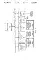
- FIG. 1is a block diagram of a radio telephone in accordance with a preferred embodiment of the invention
- FIG. 2is a block diagram of the FM receiver and RSSI detector of FIG. 1;
- FIG. 3is a block diagram of the central processing unit of FIG. 1;
- FIG. 4is a block diagram of the power control circuit of FIG. 1;
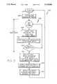
- FIG. 5is an algorithm in flow chart form suitable for execution by the CPU of FIG. 3 in deriving RSSI-based digital control signals;
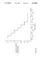
- FIG. 6is a graph of the relationship between the power amplifier output power (dB relative to nominal) and RSSI (dBm) for an illustrative application of the invention.
- FIG. 1shows a radio telephone 10 in accordance with a preferred embodiment of the invention.
- the radio telephone 10includes a user unit 12, a transceiver 14, a conventional antenna system 16, and a conventional regulated power supply, e.g., including batteries 18.
- the user unit 12provides a user/telephone interface, and includes a microphone 22 for converting sounds, e.g., messages spoken by a user or other audio data, into an electrical signal representing those sounds, called a "transmit audio signal.”
- the user unit 12also includes a speaker 24 for converting an electrical signal containing audio data, called a "receive audio signal," into sound, e.g., messages being communicated to the user.
- a mouthpiece (not shown) of the handsetcontains the microphone 22 and an earpiece thereof (not shown) contains the speaker 24.
- the user unit 12typically includes also a keypad and display (not shown).
- the transceiver 14has a transmitter 26, a receiver 28, and a central processing unit (“CPU”) 30 for controlling many of the operations of the transmitter 26 and receiver 28 (and for receiving and providing information to the user unit 12).
- CPUcentral processing unit
- the transmitter 26includes a signal processor 32 for processing (e.g., filtering and amplifying) audio signals from the microphone 22 and control signals from the CPU 30.
- the output of the signal processor 32is called the "transmit baseband signal.”
- This signalis fed to a modulator and converter 34.
- an RF carrier signalis, preferably, frequency modulated with the transmit baseband signal.
- the transmitter 26also includes a conventional, variable-gain, RF power amplifier 36 for boosting the power of the modulated RF signal from the modulator and converter 34.
- the power amplifier 36receives the modulated RF signal at a signal input 36a thereof, and produces an amplified version of the signal at its output 36b.
- the amplified signal from the power amplifier 36is fed to the antenna system 16.
- the antenna system 16includes both an antenna 38 and a duplexer 40 for full-duplex two-way conversations, i.e., for permitting the antenna 38 to be used both for transmitting the output from the power amplifier 36, and for receiving communication signals broadcast from base stations (not shown).
- the duplexer 40includes a filter arrangement, which is not separately shown.
- the receiver 28has a conventional front-end converter and mixer 44 for converting the RF signal from the duplexer 40 into an intermediate-frequency ("IF") signal.
- the receiver 28also has an FM receiver and RSSI detector 46, which both (i) extracts the received baseband signal from the RF signal, and (ii) produces an RSSI having a voltage amplitude that varies in response to the strength of the IF signal, and, thus, of the in-coming RF signal.
- the received baseband signalis fed to a conventional signal processor 45.
- the signal processor 45processes (e.g., filtering and amplifying) the received baseband signal, separating it into audio and control signals.
- the audio signalsare provided to the speaker 24, and the control signals go to the CPU 30.
- FIG. 2shows the FM receiver and RSSI detector 46 in more detail.
- the chain of boxes across the top of the drawingtogether form an FM receiver 46a.
- An IF filter 52filters the IF signal from the front-end converter and mixer 44 so as to reduce broadband noise, and thereby improve the signal-to-noise ratio.
- the IF filter 52passes its output to an IF log amplifier 54.
- an interstage filter 56further eliminates noise from the IF signal for an even better signal-to-noise ratio, and passes its output to a limiter amplifier 58.
- the output of the limiter 58is fed directly to a first input of a conventional quadrature detector 62.
- the output of the limiter amplifier 58is also shifted by 90 degrees in a phase shifter 64, and thence is provided to a second input of the quadrature detector 62.
- the quadrature detector 62performs demodulation, and its output is the received baseband signal.
- the rest of FIG. 2constitutes the RSSI detector 46b.
- Current sensors 66, 68sense the magnitude of the dc current drawn respectively by the RF amplifier 54 and by the limiter amplifier 58 from the power supply 18.
- the amounts of current drawn by amplifiers 54, 58correspond to the degree of amplification performed by them in obtaining respective pre-selected outputs, and, thus, depend on the strength of the signals received by the amplifiers 54, 58. It should be pointed out that the amplification performed by the amplifiers 54, 58 does not affect the content of the signal, since the signal is frequency modulated in the illustrated embodiment.
- the RSSI detector 46balso has a current summer 72 and an RSSI amplifier 74.
- the current summer 72sums the outputs of the current sensors 66, 68.
- the resulting signalhas a current whose magnitude corresponds to that of the IF signal.
- the RSSI amplifier 74converts this signal into an RSSI, that is, into a signal whose voltage level corresponds inversely to the magnitude of the IF signal, which, in turn, corresponds to the strength of the received RF signal.
- RSSI valuestypically are large (e.g., greater than about -60 dBm), while in outlying or fringe areas, e.g., far from transmission sources, RSSI values typically are low (e.g., less than about -100 dBm).
- RSSIreceived signal strength indicator
- the RSSI measurements specified by the standardsprovide a general indication of the strength of received communication signals for each available channel, and this indication is then used to select the appropriate channel, usually the strongest channel, for communication.
- This indicationis then used to select the appropriate channel, usually the strongest channel, for communication.
- a novel use for RSSI signalsis proposed, as will be made clear in the following discussion.
- the RSSI signal from the FM receiver and RSSI detector 46is fed to an analog-to-digital converter ("A/D") 82.
- the A/D 82converts the RSSI from an analog signal into a digital signal, whose digital values correspond to the amplitude of the analog RSSI signal.
- the A/D 82passes the digitized RSSI to the CPU 30 for processing.
- FIG. 3shows the CPU 30 in more detail.
- the CPU 30has a processor 84, a read-only memory (“ROM”) 86 for storing, e.g., a telephone operating program, a non-volatile memory (“NVM”) 88, for storing, e.g., various databases (described below) a universal asynchronous receiver/transmitter (“UART") interface 92 for communication with the keyboard and display unit of the user unit 12, input port 94 for receiving the RSSI from the A/D 82, output port 96, and a control bus 98 interconnecting all of the other CPU components, among other conventional components (not shown).
- the CPU 30stores various data concerning the RSSI, and computes a digitized power control signal using the digitized RSSI from the A/D 82, as will be described shortly.
- the radio telephone 10also has an automatic gain control circuit 100, as mentioned above, for controlling the gain of the power amplifier 36.
- the AGC circuit 100processes the digitized power control signal obtained from the output port 96 of the CPU 30 to derive an AGC signal. This AGC signal is applied to a control input 36c of the power amplifier 36 to regulate the gain of the power amplifier 36.
- the AGC circuit 100has a digital-to-analog converter ("D/A") 102 for converting the digital power control signal from the CPU 30 into an analog signal, whose voltage varies in accordance with the digital values of the digital power control signal.
- the AGC circuit 100also has a power control circuit 104.
- FIG. 4is a schematic representation of the power control circuit 104.
- An RF power detector 106e.g., a diode detector, receives a portion of the output of the power amplifier 36 as a power amplifier feedback signal, and provides a feedback voltage that is proportional to the power level of the power amplifier's output to a power control amplifier 108 at its first input 108a.
- the power control signal from the D/A 102is provided to a second input 108b of the power control amplifier 108.
- Amplifier 108is adapted with a suitable feedback-capacitor arrangement C to integrate the difference between the signals on its inputs 108a, 108b, with a gain controlled by an RC network 110.
- the integrationthus performed ensures that the AGC circuit 100 exhibits an appropriate dynamic response, i.e., that the AGC circuit 100 is not overly sensitive to transient conditions in the input signals to the power control amplifier 108.
- the output of the differential amplifier 108is the AGC signal.
- FIG. 5shows an algorithm 120 in flow chart form for deriving the power control signal based on the RSSI.
- algorithm 120starts in block 122.
- the algorithm 120initializes variables, including RSSI SUM and RSSI AVERAGE.
- the algorithm 120enters into a do-loop 126 in which the RSSI is sampled repeatedly over a period of time sufficient to provide an adequate update, e.g., over a period of approximately 2.5 seconds, or sixty-two iterations of the loop 126.
- the algorithm 120takes in plural (e.g., two) samplings of the RSSI signal from the A/D 82, preferably at fixed time intervals (e.g., at 20 msec. apart).
- the reason for taking the double sampling of the RSSIis to avoid an aberrationally low reading resulting, e.g., from temporary fading of the RF signal during its propagation to the radio telephone 10. Accordingly, the higher of the readings is selected for further processing, and, in block 130, is added to a running total, called RSSI SUM. Then, as indicated by block 132, the loop 126 is repeated (starting with block 128) until sixty- two iterations have been completed, at which time the loop 126 is exited.
- the algorithm 120calculates a time-averaged value, called RSSI AVERAGE, by dividing RSSI SUM by the number of iterations of the loop 26 (in the example, by 62). This further eliminates any false or short term fluctuations in the RSSI measurement.
- an RSSI calibration factoris added (or, e.g., otherwise applied) to the calculated RSSI AVERAGE to yield a calibrated or absolute RSSI value.
- the RSSI calibration factoris preferably stored in a calibration look-up table ("LUT") 88a in the NVM 88 of the CPU 30.
- the LUT 88ais a database in which calibration factors are stored in locations corresponding to measured RSSI values, and the channels or frequencies to which the receiver 28 (FIG. 1) can be tuned.
- the calibration factoris the entry corresponding to the particular measured RSSI value, and to the particular channel over which the communication signal that produced that value was received.
- the RSSI value provided to the CPU 30can have a transient component due to non-linearities in the frequency characteristics of the duplexer 40 (FIG. 1) and other components of the radio telephone 10. Thus, the measured RSSI's can vary from one channel to the next, despite identical strengths of the received signals on the various channels.
- the measured RSSIwill depend on the normally-otherwise-acceptable manufacturing tolerances of these components that cause their characteristics to vary from unit to unit.
- the measured RSSIwill depend on the selection of the output level of the IF and limiter amplifiers 54, 58 (FIG. 2), since that level dictates the level of currents drawn by amplifiers 54, 58 (FIG. 2), which currents are detected in deriving the RSSI. For all these reasons, RSSI calibration is appropriate.
- algorithm 120calculates, in block 136, the power amplifier output desired for the prevailing conditions indicated by the absolute RSSI just calculated. This, too, can be achieved expeditiously using an appropriate look-up table 88b stored in NVM 88 (FIG. 2) in the CPU 30 (FIG. 1). The entries in the look-up table 88b establish an RSSI/output-power relationship.
- FIG. 6depicts graphically the inverse relationship between calibrated RSSI and the power amplifier output power for an illustrative cellular-telephone application. As can readily be seen, for this application, output power increases in steps as RSSI decreases.
- nominal output powercan be used between a first threshold, e.g., about -100 dBm, and a second threshold, e.g., about -90 dBm.
- first thresholde.g., about -100 dBm
- second thresholde.g., about -90 dBm
- nominal output powercan be used for lower RSSI values, i.e., below the first threshold.
- higher output powercan be used advantageously, that is, the output power can be raised above the nominal value.
- output powercan be increased by 1 dB for each 10 dBm decrease in RSSI below the first threshold.
- the output powercan be lowered from nominal power.
- the graphshows output power being lowered by 1 dB for each 10 dBm increase in RSSI.
- the rates of increase in output power per drop in RSSI values below the first threshold and of decrease in output power per rise in RSSI values above the second thresholdcan be any desired amounts, and certainly need not be equal.
- the power amplifiercan be controlled so as to render its output power lower than the nominal output power established by applicable standards and typically targeted by conventional AGC circuits. Consequently, the power amplifier consumes less power, and battery life is therefore extended significantly, depending on the type of telephone and prevailing conditions.
- a radio telephone in accordance with the inventioncan provide the user with significantly more talktime per battery charge.
- the power amplifiercan be controlled so as to render its output power greater than the nominal value, thereby improving transmission strength when (and only when) such improvement is most needed, e.g., in fringe or outlying areas.
- the algorithm 120obtains the power control voltage that would produce the desired output power (computed in block 136), e.g., again through the use of a suitable, stored look-up table 88c.
- the entries of the power-control-voltage/amplifier output-voltage look-up table 88care preferably empirically derived to account for, and substantially eliminate, unit-to-unit variations in the responses of power amplifiers to control signals. In other words, each entry of the LUT 88c is the precise control signal needed to produce a specified output power in the power amplifier 36.
- LUT 88c identified by the target output poweris applied to D/A 102 as the power control voltage, and continues to be applied thereto until such time as a different power-control voltage is determined in block 138. Then, after step 138, the algorithm 120 returns to its starting block 122.
- a suitable methodology for deriving the calibration look-up table 88a for RSSI valuesis as follows: An RF signal generator provides RF signals to an antenna port 40b (FIG. 1) of the duplexer 40 (FIG. 1). These signals are of known power levels, and of known and tunable frequencies.
- the radio telephone 10(FIG. 1) treats each signal from the signal generator as it would a received communication signal, and derives the RSSI AVERAGE value for that signal, as described hereinabove.
- This derived RSSI AVERAGE valueis compared with a known value corresponding to that RF signal, and the difference is stored as an entry in the look-up table 88a at a location corresponding to the frequency of the applied signal.
- RSSI calibrationis performed at the radio telephone manufacturing facility.
- radio telephone 10when a communication signal is received over a voice channel, the FM receiver and RSSI detector 46 produces an RSSI signal to indicate the prevailing signal propagation conditions encountered by the received signal. A digitized version of the RSSI is supplied to the CPU 30 by receiver 28.
- the CPU 30samples this RSSI signal and derives an average value for the signal over a reasonably long period of time (e.g., 2.5 seconds). This average value is then calibrated to provide a truer indication of prevailing signal propagation conditions. To accomplish such calibration, the average RSSI value and the frequency of the received signal are used as pointers into the calibration table 88a. The resulting calibrated absolute RSSI value is used in deriving a desirable transmission power for the signal propagation conditions indicated by the RSSI. To do so, the absolute RSSI is used as a pointer into a further look-up table, 88b.
- the resulting target output power for the amplifier 36is then used to obtain a suitable power control signal, which, when applied to the AGC circuit, will produce an output power from the amplifier 36 equal to the computed target output power. This can be accomplished by using the target output power value as a pointer into look-up table 88c. The entry so located is provided to the AGC circuit 100.
- the AGC circuit 100also receives a portion of the output of the power amplifier 36 as a feedback signal, and derives an AGC signal proportional to the difference between the power control signal and the power amplifier feedback signal. Completing a feedback loop, the AGC signal is applied to the control input 360 of the power amplifier 36 so as to control its gain, and drive the power level of its output toward the target power level computed by the CPU 30.
- the output of the power amplifier 36remains at all times within a power range prescribed by applicable standards, and is increased or decreased within the power range by operation of the AGC circuit 100 in accordance with prevailing conditions indicated by the RSSI.
- the AGC circuit 100preferably drives the output power to the lowest level within the specified range that provides an adequately strong communication signal in light of prevailing propagation conditions.
Landscapes
- Engineering & Computer Science (AREA)
- Computer Networks & Wireless Communication (AREA)
- Signal Processing (AREA)
- Mobile Radio Communication Systems (AREA)
- Transmitters (AREA)
Abstract
Description
Claims (22)
Priority Applications (2)
| Application Number | Priority Date | Filing Date | Title |
|---|---|---|---|
| US07/587,004US5129098A (en) | 1990-09-24 | 1990-09-24 | Radio telephone using received signal strength in controlling transmission power |
| CA002052007ACA2052007C (en) | 1990-09-24 | 1991-09-23 | Radio telephone using received signal strength in controlling transmission power |
Applications Claiming Priority (1)
| Application Number | Priority Date | Filing Date | Title |
|---|---|---|---|
| US07/587,004US5129098A (en) | 1990-09-24 | 1990-09-24 | Radio telephone using received signal strength in controlling transmission power |
Publications (1)
| Publication Number | Publication Date |
|---|---|
| US5129098Atrue US5129098A (en) | 1992-07-07 |
Family
ID=24347933
Family Applications (1)
| Application Number | Title | Priority Date | Filing Date |
|---|---|---|---|
| US07/587,004Expired - LifetimeUS5129098A (en) | 1990-09-24 | 1990-09-24 | Radio telephone using received signal strength in controlling transmission power |
Country Status (2)
| Country | Link |
|---|---|
| US (1) | US5129098A (en) |
| CA (1) | CA2052007C (en) |
Cited By (108)
| Publication number | Priority date | Publication date | Assignee | Title |
|---|---|---|---|---|
| US5210784A (en)* | 1991-06-28 | 1993-05-11 | Lifeline Systems, Inc. | Adaptive speakerphone system |
| US5241690A (en)* | 1990-06-21 | 1993-08-31 | Telefonaktiebolaget L M Ericsson | Method for regulating power in a digital mobile telephony system |
| US5276921A (en)* | 1990-10-19 | 1994-01-04 | Matsushita Electric Industrial Co., Ltd. | Transmitter with nonlinearity correction circuit |
| WO1994006218A1 (en)* | 1992-09-04 | 1994-03-17 | Telefonaktiebolaget Lm Ericsson | A method and apparatus for regulating transmission power |
| EP0597448A1 (en)* | 1992-11-09 | 1994-05-18 | Nec Corporation | The apparatus for adjusting the efficiency of electric power amplification |
| US5345596A (en)* | 1991-06-25 | 1994-09-06 | Motorola, Inc. | Method and apparatus for establishing a communication link |
| EP0615353A1 (en)* | 1993-03-09 | 1994-09-14 | Alcatel Mobile Communication France | Method and system for controlling the power of an access packet in a mobile radiocommunication system |
| US5349630A (en)* | 1992-09-01 | 1994-09-20 | Nokia Mobile Phones, Ltd. | Radio telephone system |
| US5357513A (en)* | 1990-12-06 | 1994-10-18 | Hughes Aircraft Company | Transmission power level adjustment in radio telephony |
| EP0625833A1 (en)* | 1993-05-17 | 1994-11-23 | Sony Corporation | Transmission power control of mobile station in a mobile radio telephone system |
| US5390365A (en)* | 1991-05-20 | 1995-02-14 | Kabushiki Kaisha Toshiba | Radio communication apparatus having a received signal strength measuring function |
| US5390338A (en)* | 1990-10-05 | 1995-02-14 | Telefonaktiebolaget L M Ericsson | Method of controlling output power in a mobile radio communication system |
| US5396647A (en)* | 1992-11-03 | 1995-03-07 | Motorola, Inc. | GPS base wide area communication system site selection |
| WO1995009488A1 (en)* | 1993-09-28 | 1995-04-06 | Nokia Telecommunications Oy | Measurement of gain error in a base station receiver, and improvement in field strength measurement |
| US5446756A (en)* | 1990-03-19 | 1995-08-29 | Celsat America, Inc. | Integrated cellular communications system |
| WO1995023460A1 (en)* | 1994-02-28 | 1995-08-31 | Qualcomm Incorporated | Method and apparatus for correction and limitation of transmitter power on the reverse link of a mobile radio telephone system |
| US5457813A (en)* | 1991-09-09 | 1995-10-10 | Elektrobit Oy | Method for automatic transmission power control in a transceiver suitable for a CDMA environment employing direct sequence diffusion |
| US5457814A (en)* | 1993-10-02 | 1995-10-10 | Nokia Mobile Phones Ltd. | Power boost system for cellular telephone |
| US5471146A (en)* | 1993-06-14 | 1995-11-28 | Motorola, Inc. | Method and apparatus for measuring return loss |
| US5548616A (en)* | 1994-09-09 | 1996-08-20 | Nokia Mobile Phones Ltd. | Spread spectrum radiotelephone having adaptive transmitter gain control |
| US5548836A (en)* | 1993-07-27 | 1996-08-20 | Matsushita Electric Industrial Co., Ltd. | Diversity receiver |
| US5551066A (en)* | 1993-06-07 | 1996-08-27 | Radio Local Area Networks, Inc. | Network link controller for dynamic designation of master nodes |
| US5553316A (en)* | 1992-07-03 | 1996-09-03 | Ncr Corporation | Power control method in a wireless communication system |
| EP0735668A1 (en)* | 1995-03-30 | 1996-10-02 | AT&T IPM Corp. | High-efficient configurable power amplifier for use in a portable unit |
| US5564074A (en)* | 1993-02-05 | 1996-10-08 | Nokia Mobile Phones Ltd. | Power control apparatus and method for a radiotelephone |
| US5566201A (en)* | 1994-09-27 | 1996-10-15 | Nokia Mobile Phones Ltd. | Digital AGC for a CDMA radiotelephone |
| US5603113A (en)* | 1993-06-16 | 1997-02-11 | Oki Telecom | Automatic gain control circuit for both receiver and transmitter adjustable amplifiers including a linear signal level detector with DC blocking, DC adding, and AC removing components |
| WO1997010644A1 (en)* | 1995-09-15 | 1997-03-20 | Qualcomm Incorporated | Linearized digital automatic gain control |
| US5631921A (en)* | 1990-11-16 | 1997-05-20 | Interdigital Technology Corp. | Adaptive power control for a spread spectrum communications system and method |
| US5634200A (en)* | 1993-03-30 | 1997-05-27 | Sony Corporation | Antenna duplexer and transmitting/receiving apparatus using the same |
| US5640079A (en)* | 1994-08-29 | 1997-06-17 | Andrew Corporation | Battery charger for portable rechargeable batteries |
| US5644618A (en)* | 1991-05-31 | 1997-07-01 | Nec Corporation | Method of self-diagnosing a mobile telephone set for use in a mobile telephone switching system and a mobile telephone set to which the method is applied |
| US5689815A (en)* | 1995-05-04 | 1997-11-18 | Oki Telecom, Inc. | Saturation prevention system for radio telephone with open and closed loop power control systems |
| US5689814A (en)* | 1993-08-20 | 1997-11-18 | Hitachi, Ltd. | Radio communication apparatus with expanded dynamic range |
| US5708681A (en)* | 1996-04-23 | 1998-01-13 | Bell Communications Research, Inc. | Hybrid analog/digital method and apparatus for controlling the transmission power level of a radio transceiver |
| US5710982A (en)* | 1995-06-29 | 1998-01-20 | Hughes Electronics | Power control for TDMA mobile satellite communication system |
| US5710981A (en)* | 1995-05-23 | 1998-01-20 | Ericsson Inc. | Portable radio power control device and method using incrementally degraded received signals |
| US5722053A (en)* | 1994-09-30 | 1998-02-24 | Qualcomm Incorporated | Multiple frequency communication device |
| US5787079A (en)* | 1996-04-23 | 1998-07-28 | Unique Wireless Developments, L.L.C. | Method and apparatus for creating multiple subchannels in a single two-way radio channel |
| US5815818A (en)* | 1991-04-19 | 1998-09-29 | Nec Corporation | Cellular mobile communication system wherein service area is reduced in response to control signal contamination |
| US5845208A (en)* | 1994-03-17 | 1998-12-01 | Nokia Telecommunications Oy | Method for estimating received power and a receiver |
| US5857154A (en)* | 1994-09-30 | 1999-01-05 | Hughes Electronics Corporation | Multiprotocol mobile telephone network having high tier and low tier systems |
| US5859874A (en)* | 1994-05-09 | 1999-01-12 | Globalstar L.P. | Multipath communication system optimizer |
| US5893036A (en)* | 1997-01-30 | 1999-04-06 | Motorola, Inc. | Transmission power control method |
| US5920607A (en)* | 1995-12-29 | 1999-07-06 | Mci Communications Corporation | Adaptive wireless cell coverage |
| WO1999031798A3 (en)* | 1997-12-12 | 1999-07-22 | Koninkl Philips Electronics Nv | A communication system, device and method |
| US5937336A (en)* | 1996-12-27 | 1999-08-10 | Fujitsu Limited | Transmission/reception apparatus |
| US5978690A (en)* | 1997-02-25 | 1999-11-02 | Lucent Technologies Inc. | Reducing power consumption in low noise radiophone amplifiers |
| US5987333A (en)* | 1997-09-30 | 1999-11-16 | Nortel Networks Corporation/Corporation Nortel Networks | Communications power control |
| US6018650A (en)* | 1996-12-18 | 2000-01-25 | Aironet Wireless Communications, Inc. | Cellular communication devices with automated power level adjust |
| US6032052A (en)* | 1994-12-23 | 2000-02-29 | Nokia Mobile Phones Ltd. | Apparatus and method for data transmission |
| US6047168A (en)* | 1996-06-28 | 2000-04-04 | Telefonaktiebolaget Lm Ericsson | Device and method for radio transmitters |
| US6104918A (en)* | 1996-01-19 | 2000-08-15 | Nokia Telecommunications Oy | Method for controlling transmitting power and radio system |
| US6122529A (en)* | 1998-03-17 | 2000-09-19 | Transcept, Inc. | Simulcast with hierarchical cell structure overlay |
| US6148220A (en)* | 1997-04-25 | 2000-11-14 | Triquint Semiconductor, Inc. | Battery life extending technique for mobile wireless applications |
| US6185431B1 (en)* | 1997-06-18 | 2001-02-06 | Oki Telecom, Inc. | Mobile station closed loop output power stability system for weak signal conditions |
| GB2355341A (en)* | 1999-09-07 | 2001-04-18 | Nec Corp | Portable telephone which compensates for change of antenna impedance |
| US6226316B1 (en) | 1990-11-16 | 2001-05-01 | Interdigital Technology Corporation | Spread spectrum adaptive power control communications system and method |
| US6236863B1 (en) | 1997-03-31 | 2001-05-22 | Oki Telecom, Inc. | Comprehensive transmitter power control system for radio telephones |
| US6259682B1 (en)* | 1997-11-25 | 2001-07-10 | Uniden America Corporation | Closed loop transmitter with improved stability and accuracy over a wide range of power levels having means for maintaining constant loop gain |
| US6282177B1 (en) | 1998-03-04 | 2001-08-28 | 3Com Corporation | Method and apparatus for dynamically controlling the bias current in a receiver in response to the transmitter power |
| US6301240B1 (en) | 1998-02-19 | 2001-10-09 | Transcept, Inc. | Centrally located equipment for wireless telephone system |
| US20010048675A1 (en)* | 2000-03-29 | 2001-12-06 | Mohammed Nafie | Wireless communication |
| US6330455B1 (en)* | 1998-07-27 | 2001-12-11 | Nec Corporation | Transmission power controller for use in mobile communication terminal equipment |
| US6336042B1 (en) | 1998-06-05 | 2002-01-01 | Transcept, Inc. | Reverse link antenna diversity in a wireless telephony system |
| US6337974B1 (en)* | 1999-05-31 | 2002-01-08 | Matsushita Electric Industrial Co., Ltd. | Cellular mobile telephone terminal |
| US6339711B1 (en)* | 1997-03-14 | 2002-01-15 | Kabushiki Kaisha Toshiba | Radio apparatus |
| KR100326695B1 (en)* | 1998-03-06 | 2002-03-04 | 루센트 테크놀러지스 인크 | A method and apparatus for controlling the power radiated by a Wireless terminal in a telecommunications system |
| US6374124B1 (en) | 1997-12-24 | 2002-04-16 | Transcept, Inc. | Dynamic reallocation of transceivers used to interconnect wireless telephones to a broadband network |
| US6385173B1 (en)* | 1999-02-16 | 2002-05-07 | Telefonaktiebolaget L M Ericsson (Publ) | Adaptive control of telecommunications systems with measurements of varying time-delays |
| US6408193B1 (en)* | 1998-11-10 | 2002-06-18 | Hitachi, Ltd. | Cellular telephone |
| US6430402B1 (en)* | 1998-09-14 | 2002-08-06 | Conexant Systems, Inc. | Power amplifier saturation prevention method, apparatus, and communication system incorporating the same |
| US6480702B1 (en)* | 1996-08-01 | 2002-11-12 | Transcept, Inc. | Apparatus and method for distributing wireless communications signals to remote cellular antennas |
| US20030002452A1 (en)* | 2001-06-26 | 2003-01-02 | Sahota Gurkanwal Singh | System and method for power control calibration and a wireless communication device |
| US6504831B1 (en) | 1999-02-23 | 2003-01-07 | Lockhead Martin Corporation | Optical simulcast network with centralized call processing |
| EP0883250A3 (en)* | 1997-06-06 | 2003-03-19 | NEC Compound Semiconductor Devices, Ltd. | Mobile communication transmitter capable of selectively activating amplifiers |
| US6539234B1 (en)* | 1998-08-28 | 2003-03-25 | Matsushita Electric Industrial Co., Ltd. | Radio communication terminal and transmission power control method |
| US20030073677A1 (en)* | 2001-03-14 | 2003-04-17 | Lee Francis Y.F. | Combination of epothilone analogs and chemotherapeutic agents for the treatment of proliferative diseases |
| US6587479B1 (en) | 1999-04-21 | 2003-07-01 | Opencell Corp. | Architecture for signal distribution in wireless data network |
| US20030144019A1 (en)* | 2002-01-29 | 2003-07-31 | L-3 Communications Corporation | Cooperative transmission power control method and system for CDMA communication systems |
| US6642784B2 (en)* | 2001-05-22 | 2003-11-04 | Analog Devices, Inc. | Calibrated power amplifier module |
| US6661996B1 (en) | 1998-07-14 | 2003-12-09 | Globalstar L.P. | Satellite communication system providing multi-gateway diversity to a mobile user terminal |
| WO2003047098A3 (en)* | 2001-11-28 | 2004-02-12 | Koninkl Philips Electronics Nv | Method for determining the signal strength at the input of a tuner |
| US20040072554A1 (en)* | 2002-10-15 | 2004-04-15 | Triquint Semiconductor, Inc. | Automatic-bias amplifier circuit |
| US20040070454A1 (en)* | 2002-10-15 | 2004-04-15 | Triquint Semiconductor, Inc. | Continuous bias circuit and method for an amplifier |
| US6782335B1 (en)* | 1999-09-27 | 2004-08-24 | General Instrument Corporation | Method and system for estimating input power in a cable modem network |
| US20040174214A1 (en)* | 2002-11-06 | 2004-09-09 | Triquint Semiconductor, Inc. | Accurate power detection for a multi-stage amplifier |
| WO2004030247A3 (en)* | 2002-09-25 | 2004-11-04 | Koninkl Philips Electronics Nv | Device and method for determining the level of an input signal intended to be applied to a receiving system |
| US20040242174A1 (en)* | 2002-09-26 | 2004-12-02 | Kim Hea Joung | Automatic gain control adjustment of a radio receiver |
| US20050018630A1 (en)* | 1999-04-21 | 2005-01-27 | Opencell Corp. | Architecture for signal distribution in wireless data network |
| US20050018655A1 (en)* | 1999-04-21 | 2005-01-27 | Opencell, Inc. | Architecture for signal and power distribution in wireless data network |
| US6873643B2 (en) | 1990-11-16 | 2005-03-29 | Interdigital Technology Corporation | Spread spectrum adaptive power control communications system and method |
| US20050135502A1 (en)* | 2003-12-17 | 2005-06-23 | Triquint Semiconductor, Inc. | Method and architecture for dual-mode linear and saturated power amplifier operation |
| US20050146379A1 (en)* | 2004-01-05 | 2005-07-07 | Hiroki Sugiyama | High frequency power amplifier circuit |
| US20050162794A1 (en)* | 2003-10-30 | 2005-07-28 | Donnelly David S. | System for mitigating radiation effects on componentry in space |
| US6985782B1 (en)* | 1997-07-28 | 2006-01-10 | Sony Corporation | Audio control signal transmission apparatus and reception appartus, control system and control method using an audio control signal, program information transmission apparatus and transmission method, and program reservation apparatus and program reservation method |
| US20060199602A1 (en)* | 2005-03-01 | 2006-09-07 | Micrel, Inc. | Transmitter power level optimization and error correction technique |
| US20070083778A1 (en)* | 2005-09-29 | 2007-04-12 | Kyocera Corporation | Wireless Communication Terminal, Transmission Control Mehtod, and Computer Program |
| US20070232239A1 (en)* | 2006-03-31 | 2007-10-04 | Lawrence Der | Transceiver having multiple signal processing modes of operation |
| US20070238417A1 (en)* | 2006-04-06 | 2007-10-11 | Broadcom Corporation, A California Corporation | Access point multi-level transmission power and protocol control based on the exchange of characteristics |
| US20080051918A1 (en)* | 2006-03-31 | 2008-02-28 | Tuttle G T | Broadcast AM receiver, FM receiver and/or FM transmitter with integrated stereo audio codec, headphone drivers and/or speaker drivers |
| US20080233910A1 (en)* | 2007-03-19 | 2008-09-25 | Ahmadreza Rofougaran | Method and system for mitigating receiver saturation during simultaneous fm transmission and reception |
| US7433658B1 (en)* | 2003-09-30 | 2008-10-07 | Marvell International Ltd. | System and method for controlling true output power of a transmitter |
| US20090036073A1 (en)* | 2006-08-28 | 2009-02-05 | Jason Andrew Petro | Small signal identification device |
| US20090091381A1 (en)* | 2007-10-05 | 2009-04-09 | Oki Electric Industry Co., Ltd. | Gain control device |
| US8532566B2 (en) | 2011-06-08 | 2013-09-10 | Andrew Llc | System and method for reducing desensitization of a base station transceiver for mobile wireless repeater systems |
| US20160204828A1 (en)* | 2015-01-13 | 2016-07-14 | Hughes Network Systems, Llc | Radio based automatic level control for linear radio calibration |
| US10985851B2 (en)* | 2016-10-21 | 2021-04-20 | Worldcast Systems | Method and device for optimizing the radiofrequency power of an FM radiobroadcasting transmitter |
Citations (16)
| Publication number | Priority date | Publication date | Assignee | Title |
|---|---|---|---|---|
| US4373206A (en)* | 1979-12-28 | 1983-02-08 | Nippon Electric Co., Inc. | Transmitter control system |
| WO1984002043A1 (en)* | 1982-11-12 | 1984-05-24 | Motorola Inc | Method and apparatus for dynamically selecting transmitters for communications between a primary station and remote stations of a data communications system |
| US4475010A (en)* | 1983-05-05 | 1984-10-02 | At&T Bell Laboratories | High density cellular mobile radio communications |
| US4495648A (en)* | 1982-12-27 | 1985-01-22 | At&T Bell Laboratories | Transmitter power control circuit |
| US4556760A (en)* | 1984-06-11 | 1985-12-03 | Itt Corporation | Hand-off filter for cellular mobile radio |
| CA1205140A (en)* | 1982-11-12 | 1986-05-27 | Thomas A. Freeburg | Portable radio for zone data communication system communicating message signals between portable radio and a host computer |
| US4608711A (en)* | 1984-06-21 | 1986-08-26 | Itt Corporation | Cellular mobile radio hand-off utilizing voice channel |
| WO1987001897A1 (en)* | 1985-09-13 | 1987-03-26 | Comvik Ab | Cellular mobile telephone system and method of controlling a cellular mobile telephone system |
| US4760347A (en)* | 1987-01-20 | 1988-07-26 | Novatel Communications Ltd. | Controlled-output amplifier and power detector therefor |
| US4777653A (en)* | 1985-12-20 | 1988-10-11 | Telecommunications Radioelectriques Et Telephoniques T.R.T. | Apparatus for controlling transmission power over a digital radio communication channel |
| GB2204215A (en)* | 1987-03-31 | 1988-11-02 | Mitsubishi Electric Corp | Method and apparatus for hand-off of call-in-progress in cellular radio system |
| US4811421A (en)* | 1986-03-14 | 1989-03-07 | Christophe Havel | Transmission power control device in a radio communication transmitting/receiving station |
| EP0318033A2 (en)* | 1987-11-27 | 1989-05-31 | Nec Corporation | Handoff method for cellular digital mobile communication system and mobile station |
| US4870699A (en)* | 1986-03-26 | 1989-09-26 | General Electric Company | Method and apparatus for controlling the frequency of operation and at least one further variable operating parameter of a radio communications device |
| US4870698A (en)* | 1986-10-29 | 1989-09-26 | Oki Electric Industry Co., Ltd. | Output power control circuit for a mobile radio apparatus |
| US4885798A (en)* | 1987-01-28 | 1989-12-05 | Rockwell International Corporation | Power consumption control apparatus |
- 1990
- 1990-09-24USUS07/587,004patent/US5129098A/ennot_activeExpired - Lifetime
- 1991
- 1991-09-23CACA002052007Apatent/CA2052007C/ennot_activeExpired - Lifetime
Patent Citations (19)
| Publication number | Priority date | Publication date | Assignee | Title |
|---|---|---|---|---|
| US4373206A (en)* | 1979-12-28 | 1983-02-08 | Nippon Electric Co., Inc. | Transmitter control system |
| CA1226625A (en)* | 1982-11-12 | 1987-09-08 | Thomas A. Freeburg | Dynamic selection of transmitters in data communication system |
| WO1984002043A1 (en)* | 1982-11-12 | 1984-05-24 | Motorola Inc | Method and apparatus for dynamically selecting transmitters for communications between a primary station and remote stations of a data communications system |
| CA1205140A (en)* | 1982-11-12 | 1986-05-27 | Thomas A. Freeburg | Portable radio for zone data communication system communicating message signals between portable radio and a host computer |
| CA1219638A (en)* | 1982-11-12 | 1987-03-24 | Thomas A. Freeburg | Method and apparatus for dynamically selecting transmitters for communications between a primary station and remote stations of a data communications system |
| CA1226626A (en)* | 1982-11-12 | 1987-09-08 | Thomas A. Freeburg | Radio communications systems having overlapping receiver coverage zones |
| US4495648A (en)* | 1982-12-27 | 1985-01-22 | At&T Bell Laboratories | Transmitter power control circuit |
| US4475010A (en)* | 1983-05-05 | 1984-10-02 | At&T Bell Laboratories | High density cellular mobile radio communications |
| US4556760A (en)* | 1984-06-11 | 1985-12-03 | Itt Corporation | Hand-off filter for cellular mobile radio |
| US4608711A (en)* | 1984-06-21 | 1986-08-26 | Itt Corporation | Cellular mobile radio hand-off utilizing voice channel |
| WO1987001897A1 (en)* | 1985-09-13 | 1987-03-26 | Comvik Ab | Cellular mobile telephone system and method of controlling a cellular mobile telephone system |
| US4777653A (en)* | 1985-12-20 | 1988-10-11 | Telecommunications Radioelectriques Et Telephoniques T.R.T. | Apparatus for controlling transmission power over a digital radio communication channel |
| US4811421A (en)* | 1986-03-14 | 1989-03-07 | Christophe Havel | Transmission power control device in a radio communication transmitting/receiving station |
| US4870699A (en)* | 1986-03-26 | 1989-09-26 | General Electric Company | Method and apparatus for controlling the frequency of operation and at least one further variable operating parameter of a radio communications device |
| US4870698A (en)* | 1986-10-29 | 1989-09-26 | Oki Electric Industry Co., Ltd. | Output power control circuit for a mobile radio apparatus |
| US4760347A (en)* | 1987-01-20 | 1988-07-26 | Novatel Communications Ltd. | Controlled-output amplifier and power detector therefor |
| US4885798A (en)* | 1987-01-28 | 1989-12-05 | Rockwell International Corporation | Power consumption control apparatus |
| GB2204215A (en)* | 1987-03-31 | 1988-11-02 | Mitsubishi Electric Corp | Method and apparatus for hand-off of call-in-progress in cellular radio system |
| EP0318033A2 (en)* | 1987-11-27 | 1989-05-31 | Nec Corporation | Handoff method for cellular digital mobile communication system and mobile station |
Cited By (173)
| Publication number | Priority date | Publication date | Assignee | Title |
|---|---|---|---|---|
| US5446756A (en)* | 1990-03-19 | 1995-08-29 | Celsat America, Inc. | Integrated cellular communications system |
| US5241690A (en)* | 1990-06-21 | 1993-08-31 | Telefonaktiebolaget L M Ericsson | Method for regulating power in a digital mobile telephony system |
| US5390338A (en)* | 1990-10-05 | 1995-02-14 | Telefonaktiebolaget L M Ericsson | Method of controlling output power in a mobile radio communication system |
| US5276921A (en)* | 1990-10-19 | 1994-01-04 | Matsushita Electric Industrial Co., Ltd. | Transmitter with nonlinearity correction circuit |
| US6873643B2 (en) | 1990-11-16 | 2005-03-29 | Interdigital Technology Corporation | Spread spectrum adaptive power control communications system and method |
| US5631921A (en)* | 1990-11-16 | 1997-05-20 | Interdigital Technology Corp. | Adaptive power control for a spread spectrum communications system and method |
| US20080242367A1 (en)* | 1990-11-16 | 2008-10-02 | Interdigital Technology Corporation | Spread spectrum cellular subscriber unit |
| US6226316B1 (en) | 1990-11-16 | 2001-05-01 | Interdigital Technology Corporation | Spread spectrum adaptive power control communications system and method |
| US20050169350A1 (en)* | 1990-11-16 | 2005-08-04 | Interdigital Technology Corporaiton | Spread spectrum base station |
| US5357513A (en)* | 1990-12-06 | 1994-10-18 | Hughes Aircraft Company | Transmission power level adjustment in radio telephony |
| US5815818A (en)* | 1991-04-19 | 1998-09-29 | Nec Corporation | Cellular mobile communication system wherein service area is reduced in response to control signal contamination |
| US5390365A (en)* | 1991-05-20 | 1995-02-14 | Kabushiki Kaisha Toshiba | Radio communication apparatus having a received signal strength measuring function |
| US5644618A (en)* | 1991-05-31 | 1997-07-01 | Nec Corporation | Method of self-diagnosing a mobile telephone set for use in a mobile telephone switching system and a mobile telephone set to which the method is applied |
| US5345596A (en)* | 1991-06-25 | 1994-09-06 | Motorola, Inc. | Method and apparatus for establishing a communication link |
| US5333171A (en)* | 1991-06-28 | 1994-07-26 | Lifeline Systems, Inc. | Adaptive speakerphone system |
| US5210784A (en)* | 1991-06-28 | 1993-05-11 | Lifeline Systems, Inc. | Adaptive speakerphone system |
| US5457813A (en)* | 1991-09-09 | 1995-10-10 | Elektrobit Oy | Method for automatic transmission power control in a transceiver suitable for a CDMA environment employing direct sequence diffusion |
| US5553316A (en)* | 1992-07-03 | 1996-09-03 | Ncr Corporation | Power control method in a wireless communication system |
| US5349630A (en)* | 1992-09-01 | 1994-09-20 | Nokia Mobile Phones, Ltd. | Radio telephone system |
| US5887245A (en)* | 1992-09-04 | 1999-03-23 | Telefonaktiebolaget Lm Ericsson | Method and apparatus for regulating transmission power |
| WO1994006218A1 (en)* | 1992-09-04 | 1994-03-17 | Telefonaktiebolaget Lm Ericsson | A method and apparatus for regulating transmission power |
| US5396647A (en)* | 1992-11-03 | 1995-03-07 | Motorola, Inc. | GPS base wide area communication system site selection |
| US5483682A (en)* | 1992-11-09 | 1996-01-09 | Nec Corporation | Apparatus for controlling an efficiency control signal to be supplied to a power amplification circuit in a time division multiple access mode |
| AU675973B2 (en)* | 1992-11-09 | 1997-02-27 | Nec Corporation | The apparatus for adjusting the efficiency of electric poweramplification |
| EP0597448A1 (en)* | 1992-11-09 | 1994-05-18 | Nec Corporation | The apparatus for adjusting the efficiency of electric power amplification |
| US5564074A (en)* | 1993-02-05 | 1996-10-08 | Nokia Mobile Phones Ltd. | Power control apparatus and method for a radiotelephone |
| AU673576B2 (en)* | 1993-03-09 | 1996-11-14 | Alcatel N.V. | Access burst power control |
| FR2702614A1 (en)* | 1993-03-09 | 1994-09-16 | Alcatel Radiotelephone | Method for controlling the power of the access packet emitted by a mobile in a radiocommunication system, and system implementing this method. |
| EP0615353A1 (en)* | 1993-03-09 | 1994-09-14 | Alcatel Mobile Communication France | Method and system for controlling the power of an access packet in a mobile radiocommunication system |
| US5564075A (en)* | 1993-03-09 | 1996-10-08 | Alcatel N.V. | Method and system for controlling the power at which an access packet is sent by a mobile in a mobile radio system |
| US5634200A (en)* | 1993-03-30 | 1997-05-27 | Sony Corporation | Antenna duplexer and transmitting/receiving apparatus using the same |
| EP0625833A1 (en)* | 1993-05-17 | 1994-11-23 | Sony Corporation | Transmission power control of mobile station in a mobile radio telephone system |
| US5524287A (en)* | 1993-05-17 | 1996-06-04 | Sony Corporation | Radio communication apparatus |
| US5551066A (en)* | 1993-06-07 | 1996-08-27 | Radio Local Area Networks, Inc. | Network link controller for dynamic designation of master nodes |
| US5471146A (en)* | 1993-06-14 | 1995-11-28 | Motorola, Inc. | Method and apparatus for measuring return loss |
| US5603113A (en)* | 1993-06-16 | 1997-02-11 | Oki Telecom | Automatic gain control circuit for both receiver and transmitter adjustable amplifiers including a linear signal level detector with DC blocking, DC adding, and AC removing components |
| US5548836A (en)* | 1993-07-27 | 1996-08-20 | Matsushita Electric Industrial Co., Ltd. | Diversity receiver |
| EP0639901A3 (en)* | 1993-08-20 | 1998-11-18 | Hitachi, Ltd. | Radio communication apparatus with circuit for field strength determination |
| US5689814A (en)* | 1993-08-20 | 1997-11-18 | Hitachi, Ltd. | Radio communication apparatus with expanded dynamic range |
| CN1072412C (en)* | 1993-09-28 | 2001-10-03 | 诺基亚电信公司 | Measurement of gain error in a base station receiver, and improvement in field strength measurement |
| AU678539B2 (en)* | 1993-09-28 | 1997-05-29 | Nokia Telecommunications Oy | Measurement of gain error in a base station receiver, and improvement in field strength measurement |
| WO1995009488A1 (en)* | 1993-09-28 | 1995-04-06 | Nokia Telecommunications Oy | Measurement of gain error in a base station receiver, and improvement in field strength measurement |
| US5790944A (en)* | 1993-09-28 | 1998-08-04 | Nokia Telecommunications Oy | Measurement of gain error in a base station receiver, and improvement in field strength measurement |
| US5457814A (en)* | 1993-10-02 | 1995-10-10 | Nokia Mobile Phones Ltd. | Power boost system for cellular telephone |
| US5655220A (en)* | 1994-02-28 | 1997-08-05 | Qualcomm Incorporated | Reverse link, transmit power correction and limitation in a radiotelephone system |
| WO1995023460A1 (en)* | 1994-02-28 | 1995-08-31 | Qualcomm Incorporated | Method and apparatus for correction and limitation of transmitter power on the reverse link of a mobile radio telephone system |
| RU2134018C1 (en)* | 1994-02-28 | 1999-07-27 | Квэлкомм Инкорпорейтед | Method and device for correction and limiting of reversible radio communication and transmission power in radio telephone system |
| US5845208A (en)* | 1994-03-17 | 1998-12-01 | Nokia Telecommunications Oy | Method for estimating received power and a receiver |
| US5859874A (en)* | 1994-05-09 | 1999-01-12 | Globalstar L.P. | Multipath communication system optimizer |
| US5640079A (en)* | 1994-08-29 | 1997-06-17 | Andrew Corporation | Battery charger for portable rechargeable batteries |
| US5548616A (en)* | 1994-09-09 | 1996-08-20 | Nokia Mobile Phones Ltd. | Spread spectrum radiotelephone having adaptive transmitter gain control |
| US5566201A (en)* | 1994-09-27 | 1996-10-15 | Nokia Mobile Phones Ltd. | Digital AGC for a CDMA radiotelephone |
| EP0783801A4 (en)* | 1994-09-27 | 1999-08-18 | Nokia Mobile Phones Ltd | Digital agc for a cdma radiotelephone |
| US5857154A (en)* | 1994-09-30 | 1999-01-05 | Hughes Electronics Corporation | Multiprotocol mobile telephone network having high tier and low tier systems |
| US5722053A (en)* | 1994-09-30 | 1998-02-24 | Qualcomm Incorporated | Multiple frequency communication device |
| US5758266A (en)* | 1994-09-30 | 1998-05-26 | Qualcomm Incorporated | Multiple frequency communication device |
| US6032052A (en)* | 1994-12-23 | 2000-02-29 | Nokia Mobile Phones Ltd. | Apparatus and method for data transmission |
| EP0735668A1 (en)* | 1995-03-30 | 1996-10-02 | AT&T IPM Corp. | High-efficient configurable power amplifier for use in a portable unit |
| US5689815A (en)* | 1995-05-04 | 1997-11-18 | Oki Telecom, Inc. | Saturation prevention system for radio telephone with open and closed loop power control systems |
| US6070058A (en)* | 1995-05-04 | 2000-05-30 | Oki Telecom, Inc. | Saturation prevention system for radio telephone with open and closed loop power control systems |
| US5710981A (en)* | 1995-05-23 | 1998-01-20 | Ericsson Inc. | Portable radio power control device and method using incrementally degraded received signals |
| US5790940A (en)* | 1995-06-29 | 1998-08-04 | Hughes Electronics Corporation | Power control for TDMA mobile satellite communication system |
| US5710982A (en)* | 1995-06-29 | 1998-01-20 | Hughes Electronics | Power control for TDMA mobile satellite communication system |
| WO1997010644A1 (en)* | 1995-09-15 | 1997-03-20 | Qualcomm Incorporated | Linearized digital automatic gain control |
| US5627857A (en)* | 1995-09-15 | 1997-05-06 | Qualcomm Incorporated | Linearized digital automatic gain control |
| US5920607A (en)* | 1995-12-29 | 1999-07-06 | Mci Communications Corporation | Adaptive wireless cell coverage |
| US6104918A (en)* | 1996-01-19 | 2000-08-15 | Nokia Telecommunications Oy | Method for controlling transmitting power and radio system |
| US5787079A (en)* | 1996-04-23 | 1998-07-28 | Unique Wireless Developments, L.L.C. | Method and apparatus for creating multiple subchannels in a single two-way radio channel |
| US5708681A (en)* | 1996-04-23 | 1998-01-13 | Bell Communications Research, Inc. | Hybrid analog/digital method and apparatus for controlling the transmission power level of a radio transceiver |
| US6047168A (en)* | 1996-06-28 | 2000-04-04 | Telefonaktiebolaget Lm Ericsson | Device and method for radio transmitters |
| US6480702B1 (en)* | 1996-08-01 | 2002-11-12 | Transcept, Inc. | Apparatus and method for distributing wireless communications signals to remote cellular antennas |
| US6018650A (en)* | 1996-12-18 | 2000-01-25 | Aironet Wireless Communications, Inc. | Cellular communication devices with automated power level adjust |
| US5937336A (en)* | 1996-12-27 | 1999-08-10 | Fujitsu Limited | Transmission/reception apparatus |
| US5893036A (en)* | 1997-01-30 | 1999-04-06 | Motorola, Inc. | Transmission power control method |
| US5978690A (en)* | 1997-02-25 | 1999-11-02 | Lucent Technologies Inc. | Reducing power consumption in low noise radiophone amplifiers |
| US6339711B1 (en)* | 1997-03-14 | 2002-01-15 | Kabushiki Kaisha Toshiba | Radio apparatus |
| US6236863B1 (en) | 1997-03-31 | 2001-05-22 | Oki Telecom, Inc. | Comprehensive transmitter power control system for radio telephones |
| US20040192408A1 (en)* | 1997-04-25 | 2004-09-30 | Triquint Semiconductor, Inc. | Battery life extending technique for mobile wireless applications using bias level control |
| US6757526B1 (en) | 1997-04-25 | 2004-06-29 | Steven J. Sharp | Battery life extending technique for mobile wireless applications using bias level control |
| US7505742B2 (en)* | 1997-04-25 | 2009-03-17 | Triquint Semiconductor, Inc. | Battery life extending technique for mobile wireless applications using bias level control |
| US6148220A (en)* | 1997-04-25 | 2000-11-14 | Triquint Semiconductor, Inc. | Battery life extending technique for mobile wireless applications |
| EP0883250A3 (en)* | 1997-06-06 | 2003-03-19 | NEC Compound Semiconductor Devices, Ltd. | Mobile communication transmitter capable of selectively activating amplifiers |
| US6185431B1 (en)* | 1997-06-18 | 2001-02-06 | Oki Telecom, Inc. | Mobile station closed loop output power stability system for weak signal conditions |
| US6985782B1 (en)* | 1997-07-28 | 2006-01-10 | Sony Corporation | Audio control signal transmission apparatus and reception appartus, control system and control method using an audio control signal, program information transmission apparatus and transmission method, and program reservation apparatus and program reservation method |
| US5987333A (en)* | 1997-09-30 | 1999-11-16 | Nortel Networks Corporation/Corporation Nortel Networks | Communications power control |
| US6259682B1 (en)* | 1997-11-25 | 2001-07-10 | Uniden America Corporation | Closed loop transmitter with improved stability and accuracy over a wide range of power levels having means for maintaining constant loop gain |
| WO1999031798A3 (en)* | 1997-12-12 | 1999-07-22 | Koninkl Philips Electronics Nv | A communication system, device and method |
| US6374124B1 (en) | 1997-12-24 | 2002-04-16 | Transcept, Inc. | Dynamic reallocation of transceivers used to interconnect wireless telephones to a broadband network |
| US6301240B1 (en) | 1998-02-19 | 2001-10-09 | Transcept, Inc. | Centrally located equipment for wireless telephone system |
| US6282177B1 (en) | 1998-03-04 | 2001-08-28 | 3Com Corporation | Method and apparatus for dynamically controlling the bias current in a receiver in response to the transmitter power |
| KR100326695B1 (en)* | 1998-03-06 | 2002-03-04 | 루센트 테크놀러지스 인크 | A method and apparatus for controlling the power radiated by a Wireless terminal in a telecommunications system |
| US6122529A (en)* | 1998-03-17 | 2000-09-19 | Transcept, Inc. | Simulcast with hierarchical cell structure overlay |
| US6336042B1 (en) | 1998-06-05 | 2002-01-01 | Transcept, Inc. | Reverse link antenna diversity in a wireless telephony system |
| US6661996B1 (en) | 1998-07-14 | 2003-12-09 | Globalstar L.P. | Satellite communication system providing multi-gateway diversity to a mobile user terminal |
| US6330455B1 (en)* | 1998-07-27 | 2001-12-11 | Nec Corporation | Transmission power controller for use in mobile communication terminal equipment |
| US6539234B1 (en)* | 1998-08-28 | 2003-03-25 | Matsushita Electric Industrial Co., Ltd. | Radio communication terminal and transmission power control method |
| US6430402B1 (en)* | 1998-09-14 | 2002-08-06 | Conexant Systems, Inc. | Power amplifier saturation prevention method, apparatus, and communication system incorporating the same |
| US20060030283A1 (en)* | 1998-10-11 | 2006-02-09 | Makoto Katagishi | Cellular telephone |
| US6917823B2 (en) | 1998-11-10 | 2005-07-12 | Hitachi, Ltd. | Cellular telephone |
| US20030017840A1 (en)* | 1998-11-10 | 2003-01-23 | Hitachi, Ltd. | Cellular telephone |
| US6408193B1 (en)* | 1998-11-10 | 2002-06-18 | Hitachi, Ltd. | Cellular telephone |
| US20020132587A1 (en)* | 1998-11-10 | 2002-09-19 | Hitachi, Ltd. | Cellular telephone |
| US6385173B1 (en)* | 1999-02-16 | 2002-05-07 | Telefonaktiebolaget L M Ericsson (Publ) | Adaptive control of telecommunications systems with measurements of varying time-delays |
| US6504831B1 (en) | 1999-02-23 | 2003-01-07 | Lockhead Martin Corporation | Optical simulcast network with centralized call processing |
| US7359392B2 (en) | 1999-04-21 | 2008-04-15 | Adc Wireless Solutions, Llc | Architecture for signal distribution in wireless data networks |
| US7969965B2 (en) | 1999-04-21 | 2011-06-28 | Lgc Wireless, Inc. | Architecture for signal and power distribution in wireless data network |
| US8824457B2 (en) | 1999-04-21 | 2014-09-02 | Adc Telecommunications, Inc. | Architecture for signal and power distribution in wireless data network |
| US20040057393A1 (en)* | 1999-04-21 | 2004-03-25 | Opencell Corporation | Architecture for signal distribution in wireless data networks |
| US20110216751A1 (en)* | 1999-04-21 | 2011-09-08 | Lgc Wireless, Inc. | Architecture for signal and power distribution in wireless data network |
| US8379569B2 (en) | 1999-04-21 | 2013-02-19 | Adc Telecommunications, Inc. | Architecture for signal distribution in wireless data network |
| US9674678B2 (en) | 1999-04-21 | 2017-06-06 | Commscope Technologies Llc | Architecture for signal and power distribution in wireless data network |
| US20050018655A1 (en)* | 1999-04-21 | 2005-01-27 | Opencell, Inc. | Architecture for signal and power distribution in wireless data network |
| US10142813B2 (en) | 1999-04-21 | 2018-11-27 | Commscope Technologies Llc | Architecture for signal and power distribution in wireless data network |
| US20050018630A1 (en)* | 1999-04-21 | 2005-01-27 | Opencell Corp. | Architecture for signal distribution in wireless data network |
| US6587479B1 (en) | 1999-04-21 | 2003-07-01 | Opencell Corp. | Architecture for signal distribution in wireless data network |
| US6337974B1 (en)* | 1999-05-31 | 2002-01-08 | Matsushita Electric Industrial Co., Ltd. | Cellular mobile telephone terminal |
| GB2355341B (en)* | 1999-09-07 | 2003-07-09 | Nec Corp | Portable telephone compensable for change of antenna impedance |
| US6643497B1 (en) | 1999-09-07 | 2003-11-04 | Nec Corporation | Portable telephone compensable for change of antenna impedance |
| GB2355341A (en)* | 1999-09-07 | 2001-04-18 | Nec Corp | Portable telephone which compensates for change of antenna impedance |
| US6782335B1 (en)* | 1999-09-27 | 2004-08-24 | General Instrument Corporation | Method and system for estimating input power in a cable modem network |
| US20010048675A1 (en)* | 2000-03-29 | 2001-12-06 | Mohammed Nafie | Wireless communication |
| US7113499B2 (en)* | 2000-03-29 | 2006-09-26 | Texas Instruments Incorporated | Wireless communication |
| US20030073677A1 (en)* | 2001-03-14 | 2003-04-17 | Lee Francis Y.F. | Combination of epothilone analogs and chemotherapeutic agents for the treatment of proliferative diseases |
| US6642784B2 (en)* | 2001-05-22 | 2003-11-04 | Analog Devices, Inc. | Calibrated power amplifier module |
| US6819938B2 (en)* | 2001-06-26 | 2004-11-16 | Qualcomm Incorporated | System and method for power control calibration and a wireless communication device |
| US20050059424A1 (en)* | 2001-06-26 | 2005-03-17 | Sahota Gurkanwal Singh | System and method for power control calibration and a wireless communication device |
| US8457570B2 (en)* | 2001-06-26 | 2013-06-04 | Qualcomm, Incorporated | System and method for power control calibration and a wireless communication device |
| US20030002452A1 (en)* | 2001-06-26 | 2003-01-02 | Sahota Gurkanwal Singh | System and method for power control calibration and a wireless communication device |
| RU2297714C2 (en)* | 2001-06-26 | 2007-04-20 | Квэлкомм Инкорпорейтед | System and mode for calibration of control over the power of a radio communication arrangement |
| WO2003001701A3 (en)* | 2001-06-26 | 2003-03-27 | Qualcomm Inc | System and method for power control calibration in a wireless communication device |
| US7076266B2 (en)* | 2001-06-26 | 2006-07-11 | Qualcomm Inc | System and method for power control calibration and a wireless communication device |
| WO2003047098A3 (en)* | 2001-11-28 | 2004-02-12 | Koninkl Philips Electronics Nv | Method for determining the signal strength at the input of a tuner |
| US6954622B2 (en) | 2002-01-29 | 2005-10-11 | L-3 Communications Corporation | Cooperative transmission power control method and system for CDMA communication systems |
| US20030144019A1 (en)* | 2002-01-29 | 2003-07-31 | L-3 Communications Corporation | Cooperative transmission power control method and system for CDMA communication systems |
| US20060014508A1 (en)* | 2002-09-25 | 2006-01-19 | Francois Seneschal | Device and method for determining the level of an input signal intended to be applied to a receiving system |
| WO2004030247A3 (en)* | 2002-09-25 | 2004-11-04 | Koninkl Philips Electronics Nv | Device and method for determining the level of an input signal intended to be applied to a receiving system |
| US7127222B2 (en)* | 2002-09-26 | 2006-10-24 | Broadcom Corporation | Automatic gain control adjustment of a radio receiver |
| US20040242174A1 (en)* | 2002-09-26 | 2004-12-02 | Kim Hea Joung | Automatic gain control adjustment of a radio receiver |
| US20040072554A1 (en)* | 2002-10-15 | 2004-04-15 | Triquint Semiconductor, Inc. | Automatic-bias amplifier circuit |
| US20040070454A1 (en)* | 2002-10-15 | 2004-04-15 | Triquint Semiconductor, Inc. | Continuous bias circuit and method for an amplifier |
| US6989712B2 (en) | 2002-11-06 | 2006-01-24 | Triquint Semiconductor, Inc. | Accurate power detection for a multi-stage amplifier |
| US20040174214A1 (en)* | 2002-11-06 | 2004-09-09 | Triquint Semiconductor, Inc. | Accurate power detection for a multi-stage amplifier |
| US7010284B2 (en) | 2002-11-06 | 2006-03-07 | Triquint Semiconductor, Inc. | Wireless communications device including power detector circuit coupled to sample signal at interior node of amplifier |
| US8099066B1 (en) | 2003-09-30 | 2012-01-17 | Marvell International Ltd. | System and method for controlling true output power of a transmitter |
| US7433658B1 (en)* | 2003-09-30 | 2008-10-07 | Marvell International Ltd. | System and method for controlling true output power of a transmitter |
| US20050162794A1 (en)* | 2003-10-30 | 2005-07-28 | Donnelly David S. | System for mitigating radiation effects on componentry in space |
| US7177370B2 (en) | 2003-12-17 | 2007-02-13 | Triquint Semiconductor, Inc. | Method and architecture for dual-mode linear and saturated power amplifier operation |
| US20050135502A1 (en)* | 2003-12-17 | 2005-06-23 | Triquint Semiconductor, Inc. | Method and architecture for dual-mode linear and saturated power amplifier operation |
| US20050146379A1 (en)* | 2004-01-05 | 2005-07-07 | Hiroki Sugiyama | High frequency power amplifier circuit |
| US7333564B2 (en)* | 2004-01-05 | 2008-02-19 | Renesas Technology Corp. | High frequency power amplifier circuit |
| US20060199602A1 (en)* | 2005-03-01 | 2006-09-07 | Micrel, Inc. | Transmitter power level optimization and error correction technique |
| US7398101B2 (en) | 2005-03-01 | 2008-07-08 | Micrel, Inc. | Transmitter power level optimization and error correction technique |
| US7561859B2 (en)* | 2005-09-29 | 2009-07-14 | Kyocera Corporation | Wireless communication terminal, transmission control method, and computer program |
| US20070083778A1 (en)* | 2005-09-29 | 2007-04-12 | Kyocera Corporation | Wireless Communication Terminal, Transmission Control Mehtod, and Computer Program |
| US20080051918A1 (en)* | 2006-03-31 | 2008-02-28 | Tuttle G T | Broadcast AM receiver, FM receiver and/or FM transmitter with integrated stereo audio codec, headphone drivers and/or speaker drivers |
| US8521099B2 (en)* | 2006-03-31 | 2013-08-27 | Silicon Laboratories Inc. | Transceiver having multiple signal processing modes of operation |
| US20070232239A1 (en)* | 2006-03-31 | 2007-10-04 | Lawrence Der | Transceiver having multiple signal processing modes of operation |
| US8174415B2 (en) | 2006-03-31 | 2012-05-08 | Silicon Laboratories Inc. | Broadcast AM receiver, FM receiver and/or FM transmitter with integrated stereo audio codec, headphone drivers and/or speaker drivers |
| US8264387B2 (en) | 2006-03-31 | 2012-09-11 | Silicon Laboratories Inc. | Transceiver having multiple signal processing modes of operation |
| US20080049817A1 (en)* | 2006-03-31 | 2008-02-28 | Silicon Laboratories, Inc. | Transceiver having multiple signal processing modes of operation |
| US7583625B2 (en)* | 2006-04-06 | 2009-09-01 | Broadcom Corporation | Access point multi-level transmission power and protocol control based on the exchange of characteristics |
| US20070238417A1 (en)* | 2006-04-06 | 2007-10-11 | Broadcom Corporation, A California Corporation | Access point multi-level transmission power and protocol control based on the exchange of characteristics |
| US7873337B2 (en)* | 2006-08-28 | 2011-01-18 | Jason Andrew Petro | Small signal identification device |
| US20090036073A1 (en)* | 2006-08-28 | 2009-02-05 | Jason Andrew Petro | Small signal identification device |
| US20080233910A1 (en)* | 2007-03-19 | 2008-09-25 | Ahmadreza Rofougaran | Method and system for mitigating receiver saturation during simultaneous fm transmission and reception |
| US7933568B2 (en)* | 2007-03-19 | 2011-04-26 | Broadcom Corporation | Method and system for mitigating receiver saturation during simultaneous FM transmission and reception |
| US20090091381A1 (en)* | 2007-10-05 | 2009-04-09 | Oki Electric Industry Co., Ltd. | Gain control device |
| US8532566B2 (en) | 2011-06-08 | 2013-09-10 | Andrew Llc | System and method for reducing desensitization of a base station transceiver for mobile wireless repeater systems |
| US9553656B2 (en) | 2011-06-08 | 2017-01-24 | Andrew Wireless Systems Gmbh | System and method for reducing desensitization of a base station transceiver for mobile wireless repeater systems |
| US10009090B2 (en) | 2011-06-08 | 2018-06-26 | Andrew Wireless Systems Gmbh | System and method for reducing desensitization of a base station transceiver for mobile wireless repeater systems |
| US20160204828A1 (en)* | 2015-01-13 | 2016-07-14 | Hughes Network Systems, Llc | Radio based automatic level control for linear radio calibration |
| US9667312B2 (en)* | 2015-01-13 | 2017-05-30 | Hughes Network Systems, Llc | Radio based automatic level control for linear radio calibration |
| US10985851B2 (en)* | 2016-10-21 | 2021-04-20 | Worldcast Systems | Method and device for optimizing the radiofrequency power of an FM radiobroadcasting transmitter |
Also Published As
| Publication number | Publication date |
|---|---|
| CA2052007A1 (en) | 1992-03-25 |
| CA2052007C (en) | 2002-07-30 |
Similar Documents
| Publication | Publication Date | Title |
|---|---|---|
| US5129098A (en) | Radio telephone using received signal strength in controlling transmission power | |
| US6128477A (en) | System for improving the dynamic range of transmitter power measurement in a cellular telephone | |
| US6166598A (en) | Power amplifying circuit with supply adjust to control adjacent and alternate channel power | |
| US6226507B1 (en) | Apparatus and method for selecting between a plurality of antennas utilized by a microcellular communications terminal for reception of a signal | |
| EP0812064B1 (en) | Reception automatic gain control system and method | |
| US7693491B2 (en) | Method and system for transmitter output power compensation | |
| US5107225A (en) | High dynamic range closed loop automatic gain control circuit | |
| JP4610697B2 (en) | Transmission power control method and wireless communication apparatus | |
| JPH11187463A (en) | Mobile radio receiver | |
| US6081564A (en) | Apparatus and methods for tracking power level of received signal in code division multiple access communication system | |
| US20030006839A1 (en) | Extended range power detector and amplifier and method | |
| JP4286455B2 (en) | Gain control circuit and method for providing gain control of variable amplifier using pilot signal | |
| US5873046A (en) | System for communicating in analog or digital mode and mobile station employing the same | |
| KR19990036990A (en) | Rf transmitter with temperature compensated output power level control circuit and method thereof | |
| JP4911088B2 (en) | Wireless communication apparatus and wireless communication method | |
| KR100316685B1 (en) | An automatic control apparatus for front and rear attenuators in RF repeater and method therefor | |
| US6832098B1 (en) | Portable telephone | |
| US20070147554A1 (en) | Receiver and transmitter/receiver | |
| JP4460678B2 (en) | Frequency analyzer | |
| US5261119A (en) | Signal level measuring system for a radio receiver | |
| US20040029539A1 (en) | Receiver | |
| JP2009177568A (en) | Receiving device and electronic device using the same | |
| EP0795967A1 (en) | Power saving method for radio receiver | |
| JPH05344016A (en) | Power saving device for FM wireless receiver | |
| JPH06260958A (en) | Automatic electric power control circuit and radio communications equipment |
Legal Events
| Date | Code | Title | Description |
|---|---|---|---|
| AS | Assignment | Owner name:NOVATEL, 1020 64TH AVENUE, N.W., A CANADIAN CORP. Free format text:ASSIGNMENT OF ASSIGNORS INTEREST.;ASSIGNORS:MC GIRR, ANDREW E.;CASSIDY, BARRIE J.;REEL/FRAME:005470/0665 Effective date:19900918 | |
| STCF | Information on status: patent grant | Free format text:PATENTED CASE | |
| FEPP | Fee payment procedure | Free format text:PAYOR NUMBER ASSIGNED (ORIGINAL EVENT CODE: ASPN); ENTITY STATUS OF PATENT OWNER: LARGE ENTITY | |
| FPAY | Fee payment | Year of fee payment:4 | |
| AS | Assignment | Owner name:NOVATEL INC, CANADA Free format text:ASSIGNMENT OF ASSIGNORS INTEREST;ASSIGNOR:NOVATEL COMMUNICATIONS LTD.;REEL/FRAME:008246/0864 Effective date:19961001 | |
| AS | Assignment | Owner name:NOVATEL WIRELESS SOLUTIONS, INC., ARKANSAS Free format text:ASSIGNMENT OF ASSIGNORS INTEREST;ASSIGNOR:NOVATEL, INC.;REEL/FRAME:008604/0014 Effective date:19970324 | |
| AS | Assignment | Owner name:ARGO GLOBAL CAPITAL, INC., (AGENT), MASSACHUSETTS Free format text:SECURITY INTEREST;ASSIGNOR:NOVATEL WIRELESS SOLUTIONS, INC.;REEL/FRAME:010299/0713 Effective date:19990624 | |
| FEPP | Fee payment procedure | Free format text:PAYER NUMBER DE-ASSIGNED (ORIGINAL EVENT CODE: RMPN); ENTITY STATUS OF PATENT OWNER: LARGE ENTITY Free format text:PAYOR NUMBER ASSIGNED (ORIGINAL EVENT CODE: ASPN); ENTITY STATUS OF PATENT OWNER: LARGE ENTITY | |
| FPAY | Fee payment | Year of fee payment:8 | |
| AS | Assignment | Owner name:VENTURE BANKING GROUP, A DIVISION OF CUPERTINO NAT Free format text:SECURITY INTEREST;ASSIGNOR:NOVATEL WIRELESS, INC.;REEL/FRAME:010514/0168 Effective date:19991012 | |
| AS | Assignment | Owner name:NOVATEL WIRELESS, INC., CALIFORNIA Free format text:RELEASE;ASSIGNOR:ARGO GLOBAL CAPITAL, INC. AS AGENT;REEL/FRAME:010742/0500 Effective date:20000330 | |
| AS | Assignment | Owner name:SANMINA-SCI CORPORATION, CALIFORNIA Free format text:SECURITY AGREEMENT;ASSIGNOR:NOVATEL WIRELESS, INC.;REEL/FRAME:012343/0402 Effective date:20020112 | |
| AS | Assignment | Owner name:SILICON VALLEY BANK, CALIFORNIA Free format text:SECURITY AGREEMENT;ASSIGNOR:NOVATEL WIRELESS, INC.;REEL/FRAME:012721/0818 Effective date:20011129 | |
| FPAY | Fee payment | Year of fee payment:12 | |
| AS | Assignment | Owner name:BANK OF AMERICA, N.A., CALIFORNIA Free format text:SECURITY AGREEMENT;ASSIGNOR:NOVATEL WIRELESS SOLUTIONS, INC.;REEL/FRAME:017083/0985 Effective date:20051229 | |
| AS | Assignment | Owner name:NOVATEL WIRELESS, INC., CALIFORNIA Free format text:RELEASE;ASSIGNOR:SILICON VALLEY BANK;REEL/FRAME:017537/0029 Effective date:20051222 | |
| AS | Assignment | Owner name:NOVATEL WIRELESS, INC., CALIFORNIA Free format text:RELEASE OF SECURITY INTEREST;ASSIGNOR:SANMINA-SCI CORPORATION;REEL/FRAME:017297/0819 Effective date:20060109 | |
| AS | Assignment | Owner name:NOVATEL WIRELESS INC, CALIFORNIA Free format text:RELEASE;ASSIGNOR:SILICON VALLEY BANK;REEL/FRAME:023796/0591 Effective date:20100114 | |
| AS | Assignment | Owner name:NOVATEL WIRELESS, INC.,CALIFORNIA Free format text:RELEASE BY SECURED PARTY;ASSIGNOR:BANK OF AMERICA, N.A.;REEL/FRAME:024492/0922 Effective date:20100608 Owner name:NOVATEL WIRELESS SOLUTIONS, INC.,CALIFORNIA Free format text:RELEASE BY SECURED PARTY;ASSIGNOR:BANK OF AMERICA, N.A.;REEL/FRAME:024492/0922 Effective date:20100608 | |
| AS | Assignment | Owner name:UBS AG, STAMFORD BRANCH, AS COLLATERAL AGENT,CONNE Free format text:PATENT SECURITY AGREEMENT;ASSIGNOR:NOVATEL WIRELESS SOLUTIONS, INC.;REEL/FRAME:024547/0001 Effective date:20100610 | |
| AS | Assignment | Owner name:NOVATEL WIRELESS SOLUTIONS, INC., CALIFORNIA Free format text:RELEASE OF SECURITY INTEREST IN INTELLECTUAL PROPERTY COLLATERAL AT REEL/FRAME NO. 24547/0001;ASSIGNOR:UBS AG, STAMFORD BRANCH, AS COLLATERAL AGENT;REEL/FRAME:024697/0080 Effective date:20100713 | |
| AS | Assignment | Owner name:NOVA INTELLECTUAL SOLUTIONS LLC, TEXAS Free format text:ASSIGNMENT OF ASSIGNORS INTEREST;ASSIGNOR:STRATEGIC INTELLECTUAL SOLUTIONS LLC;REEL/FRAME:047859/0921 Effective date:20141119 | |
| AS | Assignment | Owner name:NOVATEL WIRELESS, INC., CALIFORNIA Free format text:ASSIGNMENT OF ASSIGNORS INTEREST;ASSIGNOR:NOVA INTELLECTUAL SOLUTIONS LLC;REEL/FRAME:047868/0235 Effective date:20181024 |