US5128848A - Operating light - Google Patents
Operating lightDownload PDFInfo
- Publication number
- US5128848A US5128848AUS07/501,615US50161590AUS5128848AUS 5128848 AUS5128848 AUS 5128848AUS 50161590 AUS50161590 AUS 50161590AUS 5128848 AUS5128848 AUS 5128848A
- Authority
- US
- United States
- Prior art keywords
- fresnel lens
- reflector
- fact
- light according
- operating light
- Prior art date
- Legal status (The legal status is an assumption and is not a legal conclusion. Google has not performed a legal analysis and makes no representation as to the accuracy of the status listed.)
- Expired - Fee Related
Links
Images


Classifications
- F—MECHANICAL ENGINEERING; LIGHTING; HEATING; WEAPONS; BLASTING
- F21—LIGHTING
- F21V—FUNCTIONAL FEATURES OR DETAILS OF LIGHTING DEVICES OR SYSTEMS THEREOF; STRUCTURAL COMBINATIONS OF LIGHTING DEVICES WITH OTHER ARTICLES, NOT OTHERWISE PROVIDED FOR
- F21V5/00—Refractors for light sources
- F21V5/02—Refractors for light sources of prismatic shape
- F—MECHANICAL ENGINEERING; LIGHTING; HEATING; WEAPONS; BLASTING
- F21—LIGHTING
- F21S—NON-PORTABLE LIGHTING DEVICES; SYSTEMS THEREOF; VEHICLE LIGHTING DEVICES SPECIALLY ADAPTED FOR VEHICLE EXTERIORS
- F21S8/00—Lighting devices intended for fixed installation
- F21S8/04—Lighting devices intended for fixed installation intended only for mounting on a ceiling or the like overhead structures
- F21S8/043—Lighting devices intended for fixed installation intended only for mounting on a ceiling or the like overhead structures mounted by means of a rigid support, e.g. bracket or arm
- F—MECHANICAL ENGINEERING; LIGHTING; HEATING; WEAPONS; BLASTING
- F21—LIGHTING
- F21V—FUNCTIONAL FEATURES OR DETAILS OF LIGHTING DEVICES OR SYSTEMS THEREOF; STRUCTURAL COMBINATIONS OF LIGHTING DEVICES WITH OTHER ARTICLES, NOT OTHERWISE PROVIDED FOR
- F21V14/00—Controlling the distribution of the light emitted by adjustment of elements
- F21V14/06—Controlling the distribution of the light emitted by adjustment of elements by movement of refractors
- F—MECHANICAL ENGINEERING; LIGHTING; HEATING; WEAPONS; BLASTING
- F21—LIGHTING
- F21V—FUNCTIONAL FEATURES OR DETAILS OF LIGHTING DEVICES OR SYSTEMS THEREOF; STRUCTURAL COMBINATIONS OF LIGHTING DEVICES WITH OTHER ARTICLES, NOT OTHERWISE PROVIDED FOR
- F21V3/00—Globes; Bowls; Cover glasses
- F21V3/02—Globes; Bowls; Cover glasses characterised by the shape
- F—MECHANICAL ENGINEERING; LIGHTING; HEATING; WEAPONS; BLASTING
- F21—LIGHTING
- F21V—FUNCTIONAL FEATURES OR DETAILS OF LIGHTING DEVICES OR SYSTEMS THEREOF; STRUCTURAL COMBINATIONS OF LIGHTING DEVICES WITH OTHER ARTICLES, NOT OTHERWISE PROVIDED FOR
- F21V5/00—Refractors for light sources
- F21V5/04—Refractors for light sources of lens shape
- F21V5/045—Refractors for light sources of lens shape the lens having discontinuous faces, e.g. Fresnel lenses
- F—MECHANICAL ENGINEERING; LIGHTING; HEATING; WEAPONS; BLASTING
- F21—LIGHTING
- F21V—FUNCTIONAL FEATURES OR DETAILS OF LIGHTING DEVICES OR SYSTEMS THEREOF; STRUCTURAL COMBINATIONS OF LIGHTING DEVICES WITH OTHER ARTICLES, NOT OTHERWISE PROVIDED FOR
- F21V7/00—Reflectors for light sources
- F21V7/0025—Combination of two or more reflectors for a single light source
- F—MECHANICAL ENGINEERING; LIGHTING; HEATING; WEAPONS; BLASTING
- F21—LIGHTING
- F21V—FUNCTIONAL FEATURES OR DETAILS OF LIGHTING DEVICES OR SYSTEMS THEREOF; STRUCTURAL COMBINATIONS OF LIGHTING DEVICES WITH OTHER ARTICLES, NOT OTHERWISE PROVIDED FOR
- F21V7/00—Reflectors for light sources
- F21V7/22—Reflectors for light sources characterised by materials, surface treatments or coatings, e.g. dichroic reflectors
- F21V7/28—Reflectors for light sources characterised by materials, surface treatments or coatings, e.g. dichroic reflectors characterised by coatings
- F—MECHANICAL ENGINEERING; LIGHTING; HEATING; WEAPONS; BLASTING
- F21—LIGHTING
- F21V—FUNCTIONAL FEATURES OR DETAILS OF LIGHTING DEVICES OR SYSTEMS THEREOF; STRUCTURAL COMBINATIONS OF LIGHTING DEVICES WITH OTHER ARTICLES, NOT OTHERWISE PROVIDED FOR
- F21V21/00—Supporting, suspending, or attaching arrangements for lighting devices; Hand grips
- F21V21/14—Adjustable mountings
- F21V21/26—Pivoted arms
- F21V21/28—Pivoted arms adjustable in more than one plane
- F—MECHANICAL ENGINEERING; LIGHTING; HEATING; WEAPONS; BLASTING
- F21—LIGHTING
- F21V—FUNCTIONAL FEATURES OR DETAILS OF LIGHTING DEVICES OR SYSTEMS THEREOF; STRUCTURAL COMBINATIONS OF LIGHTING DEVICES WITH OTHER ARTICLES, NOT OTHERWISE PROVIDED FOR
- F21V7/00—Reflectors for light sources
- F21V7/0008—Reflectors for light sources providing for indirect lighting
- F—MECHANICAL ENGINEERING; LIGHTING; HEATING; WEAPONS; BLASTING
- F21—LIGHTING
- F21W—INDEXING SCHEME ASSOCIATED WITH SUBCLASSES F21K, F21L, F21S and F21V, RELATING TO USES OR APPLICATIONS OF LIGHTING DEVICES OR SYSTEMS
- F21W2131/00—Use or application of lighting devices or systems not provided for in codes F21W2102/00-F21W2121/00
- F21W2131/20—Lighting for medical use
- F21W2131/205—Lighting for medical use for operating theatres
Definitions
- This inventionconcerns an operating light with one or several spot-lights, each with a light source that is shielded in the direction of radiation by a counter-reflector such that the stream of light is focused by a reflector onto an optical system closing off the housing in the direction of radiation.
- This optical systemconsists of several disks or coatings, of which one disk or coating reflects or absorbs infrared in the same way. These disks or coatings make the operating light heavy and the hot rays, not carried off, heat the operating light over a long period of operation. Even the infrared-reflecting disks pick up heat over long periods of operation and then irradiate it.
- the object of the inventionis to further develop an operating light of the initially-mentioned type, such that an almost homogeneous illumination of a deep surgical wound is guaranteed.
- the optical systemincludes a Fresnel lens made of annular prisms having a dioptric central region and a catadioptric edge region, and that the annular prisms are configured such that the light beams emanating from the Fresnel lens cut the optical axis at a distance from the Fresnel lens that is all the greater the shorter the distance with which the light beams emanate from the Fresnel lens is away from the optical axis.
- the advantages of the inventionlie particularly in the fact that the focal point of the different light beams generated by the Fresnel lens lie at a different distance from the Fresnel lens.
- the light beams generated by the light source(s) and the Fresnel lensare directed such that there results, in a wide range of distances from the Fresnel lens, an approximately parallel cone of light whose light distribution in the region of the surgical wound remains approximately homogeneous even with different working distances. Guaranteed by the invention is a good shading, depth shading and depth illumination of the wound cavity, over a great working depth.
- the homogeneous distribution of lightprovides for a constant shadow generation of the working range, which is essential for the work of the surgeon in order to enable stereoscopic vision and, therewith, an estimation of the smallest distances, even in a wound cavity.
- the reflectoris constructed as a flat hyperboloid in order to achieve an extremely flat method of construction.
- the reflection coatingis preferably deposited on a glass body and structured such that it substantially reflects visible light, and on the other hand substantially permits infrared radiation to pass through. In this manner, only visible light is irradiated onto the Fresnel lens. The infrared radiation is eliminated from the working region of the operating light.
- the reflection coating at the edge (rim) of the reflectoris preferably deposited thicker than at the apex of the reflector.
- the Fresnel lens in accordance with the inventioncan be of acrylic glass or similar material that is sprayed on or poured.
- Another embodiment of the inventionis obtained by a controllable mobility of the hyperboloid reflector unit relative to the Fresnel lens system. Achieved by this mobility is an advantageous focusing capability of the spotlight. Resulting additionally, is a homogenizing of the field of illumination, if, for example, two, three or more individual spotlights of an operating light are defocused by a like amount. The light beams formed by the dioptric and by the catadioptric lens portion of the Fresnel lens then wander by like amounts from or toward the optical axis, having as a consequence either a uniform expansion or narrowing of the field of illumination.
- the lens system in accordance with the inventionRetained in each case by the lens system in accordance with the invention is the great advantage that, with each adjusted size of the illuminated field of operation, a homogeneous light distribution is also set in deeper-lying regions of the wound cavity.
- the operating lighthas a good depth sharpness, without which the position of the operating light need be subsequently corrected as the operation progresses.
- the Fresnel lensis constructed of a throughpass basic disk that displays in the rim region annular prisms whose vertex rings and flanks point toward the reflector and form the catadioptric region.
- the basic disklikewise has in its central region annular prisms whose apices are also directed toward the reflector.
- a second Fresnel lensPlaced in the central region, over the basic disk, is a second Fresnel lens whose annular prisms are directed away from the reflector and which, with the opposingly-directed annular prisms of the throughgoing basic disk and an air gap included therebetween, forms the dioptric lens region.
- the height of the apex rings of the annular prisms of the catadioptric rim regiondecreases with increasing distance from the optical center axis.
- the flanks of these annular prisms inclined toward the optical axisbecome steeper with increasing distance from the optical center axis, while the radially-outward inclined flanks of these annular prisms are less inclined with increasing distance from the optical center axis.
- the refractive flanks of the lamp-side and light-output-side annular prismslie opposite to one another.
- the refractive flankslie more toward the horizontal than they fall off on the light-output side.
- the refractive flanks of the annular prisms of the central region of the Fresnel lensform, with increasing distance to the optical center axis, a growing angle toward the horizontal.
- the lamps, the counter reflector and the reflectorform a structural unit which, compared to the Fresnel lens that is rigidly joined with the housing, is arranged in movable fashion.
- a movement of this structural unit relative to the Fresnel lensresults in an enlargement of the field of illumination, so that the surgeon, with an appropriate movement, can homogeneously illuminate an enlarged field of operation.
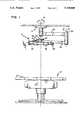
- FIG. 1shows a schematic representation of the arrangement of a new operating light above an operating table
- FIG. 2shows a schematic, sectional representation of an individual spotlight of the new operating light
- FIG. 3shows a representation of the main radiation conduction of a light source by the individual spotlight
- FIG. 4shows a schematic representation of the path of the rays for individual light beams after passing through the Fresnel lens
- FIG. 5A and 5Bshows a greatly simplified representation of light conduction from an individual spotlight into a small illuminated field
- FIG. 6A and 6Bshows a representation similar to the one in FIG. 5 for light conduction from an individual spotlight into a large illuminated operating field
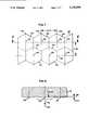
- FIG. 7shows an enlarged view onto a scattering structure of the Fresnel lens
- FIG. 8shows a cut along the line 3'--' in FIG. 7.
- an operating light 10is suspended in customary fashion above an operating table 12 by means of a ceiling attachment 14, individually as represented, or in combination with other, same, larger or smaller, operating lights.
- the suspensionis formed by a swivel joint 16, about whose axis the light 10 can be swung by at least 360°.
- the suspension for the lightfurther consists of several arms that are joined together by means of links.
- connecting to the link 16is an arm 18 and to this arm 18, via a double link 20, an arm 22 is linked and capable of being swung about its longitudinal axis, and that arm 22 carries, via an axle 24, a member 26 of the operating light 10.
- An operating light of the type describedcan display one to seven individual spotlights 25, as will be described in more detail below with the aid of FIG. 2.
- each individual spotlight 25is accessible from the top side, i.e. from the side lying opposite to the light-radiating side of the member 26, after removing a detachable cover 30, which considerably simplifies replacing light sources 50, carrying out maintenance, cleaning, adjusting, etc.
- each individual spotlight 25displays a closed underside 34 that carries a Fresnel lens 60 in a rigid skirting, described in more detail later.
- Produced via a releasable attachment 36is a connection to a carrier 38 that passes over into a flanged opening 40 in which a reflector system 42 with light source can move.
- the reflector system 42consists of a carrier 44 in whose center is located an adjustable mounting 46 for a light source 50, preferably a halogen lamp.
- the mounting 46is removable from the carrier 44 for replacing the light source 50. Brought out from the mounting 46 are flexible electrical connections.
- the total radiation emanating from the light source 50is hampered from direct irradiation in the direction toward the covering disk, structured as a Fresnel lens 60, by a counter reflector 52, and is reflected back.
- This principal reflector 54consists of glass and, in the form of embodiment represented, is a hyperboloid.
- a hyperboloid reflectorhas the advantage of being low and is easily produced from glass.
- the reflector 54is smaller in diameter than the light output area of the Fresnel lens 60. Since, however, the amount of light is collected via the smaller reflector 54, a high degree of depth illumination in the operating field results, which is desirable and advantageous.
- a reflection coating 53that is substantially pervious for infrared radiation and, which reflects the visible radiation toward the Fresnel lens 60, as is described in more detail in the following.
- the thickness of the reflection coating 53increases toward the rim of the reflector 54.
- the beam generated by a coil 66 in the light source 50can first be filtered in the shell or wall of the light source 50.
- a halogen lamp 50emits a large component of infrared radiation that radiates either directly, like a ray 68 from the coil 66 toward the reflector 54, or strikes, via the counter reflector 52, like a ray 78, against the reflector 54, the reflection coating 53 is constructed as a conversion filter.
- rays 68are substantially (approximately 70%) deflected as visible light rays 70 in the direction of the Fresnel lens 60
- infrared rays 72do pass through and are diffusedly distributed on the back side of the reflector 54 by a coating 57.
- an opening 59Located in the center of the reflector 54 is an opening 59 wherethrough is accomplished not only the equipping with a socket for the lamp 50, but also through which portions of infrared rays are led away from the reflector system 42.
- FIG. 2Another measure for filtering out undesired heat radiation and for generating a cold light in the operating field is represented by the arrangement of a filter disk 56 (FIG. 2) at the lower edge of the reflector 54.
- a filter disk 56FIG. 2
- the largest, optically-effective diameter of the Fresnel lens 60comes to 190 mm, and the diameter of the reflector 54 is about 120 mm in the optically effective region.
- the distance from the lower rim of the reflector 54 to the center plane of the Fresnel lens 60now amounts to 37.7 mm.
- the largest optically effective diameter of the Fresnel lens 60amounts to about 250 mm and the optically largest diameter of the reflector lies at about 120 mm.
- the distance from the lower rim of the reflector 54 to the center plane of the Fresnel lens 60amounts to 70 mm.
- subsequently usedcan be the same reflector unit with a reflector output opening of about 120 mm and an apex height of only about 20 mm for different sizes of individual spotlights, which lowers the manufacturing costs.
- the circular-shaped Fresnel lens 60 forming the light outputis larger in diameter than the reflector 54 and consists of a dioptric central region and of an annular catadioptric rim region, which is best brought out in FIG. 5.
- the light-output-side, lower part of the Fresnel lens 60consists of a part 61 passing over the entire diameter, which, in the rim region 62 represents the sole catadioptric lens system, while in the central region 64 another Fresnel lens 63 is put on and inserted for the purpose of achromatizing.
- the light rays occurring there from the reflector 54are deflected by a series of annularly-constructed prisms 65 (FIG. 3).
- the flank inclinations a, b and the height H of the annular prisms of the Fresnel lens 60are selected such that in the operating field an approximately homogeneous distribution of illumination intensities is obtained, even over a predetermined depth region, which will be explained in more detail with the aid of FIG. 4.
- rays 68are deflected from the reflector 54 into rays 70 such that they strike against inclined surfaces 96 of the prism rings 65 and are diffused into the material of the Fresnel lens 60.
- the refracted ray 100runs up to the back wall of the oppositely-located inclined prism surface 98 and is totally reflected there so that these light rays 102 first run on further in the material of the Fresnel lens 60, and finally come out in the direction toward the operating field as rays 104.
- the short distance 69 from the reflector 54 to the Fresnel lens 60is diffracted into the Fresnel lens 60.
- the flanks 98 directed toward the operating axis 67 of the catadioptric prisms 65, at which a total reflection occursbecome relatively flatter with increasing distance from the optical axis 67, the corresponding flank inclination, ⁇ , therefore decreases toward the rim.
- the spotlightattains, from the catadioptric region 62 of the Fresnel lens 60, a desired ray pattern as will be laid out in more detail with the aid of FIG. 4, 5 and 6.
- flanks 92 of the annular prisms 61' of the throughgoing Fresnel disk 61 directed toward the light source 50The inclination of oppositely-lying flanks 90 and 92 to the horizontal is in each case different enough so that the radiation 94 from the dioptric central region 64 occurs almost axis-parallel to the optical axis of the Fresnel lens 60; compare in particular FIG. 4.
- the flanks 92 of the throughgoing Fresnel disk 61 inclined upwardly toward the optical axishave a slope that increases with increasing distance from the optical axis 67.
- the flanks 90 of the annular prisms 63' of the Fresnel disk 63 directed downwardly toward the optical axis 67display an increasing slope with increasing distance from the optical axis 67.
- the special configuration of the annular prisms 65respectively 63', 61' and the selected flank slopes, ⁇ , ⁇ cause the light beams coming from the Fresnel lens to cut the optical axis 67 at a distance a from the Fresnel lens that is all the greater the shorter the distance b, the distance between where the light beams emanate from the Fresnel lens 60 and the optical axis 67.
- the light beams that come out at the rim of the Fresnel lens 60are most strongly refracted toward the optical axis and cut the optical axis 67 at the distance al.
- the represented center beamcomes out from the Fresnel lens 60 at the distance b2 from the optical axis and cuts the optical axis at the distance a2.
- the beam of light coming out from the dioptric region of the Fresnel lens 60 near the optical axis 67 at the distance b3,has an external ray that runs almost parallel to the optical axis, the middle ray cuts the optical axis 67 at a great distance a3 from the Fresnel lens 60.
- the distances a1, a2, a3give the point of intersection of each center ray of the light beam of concern with the optical axis 67.
- Achieved by the different focusing of the different light beamsis that a homogeneous light intensity is possible over a relatively wide range of depths, and therewith, a homogeneous illumination of a deep surgical wound is possible. Undesired variations in light distribution are to a great extent eliminated.
- FIG. 5A and 5BRepresented schematically in FIG. 5A and 5B is the homogeneity in the illuminated operating field 114 that is achievable by means of the Fresnel lens 60 with its catadioptric region 62 and dioptric region 64 for an ideal case of exact focusing of the lamp 50 in the optical system.
- Resulting under an individual spotlight 25is a concentrically illuminated small field of operation 114, by superimposing the ray guide 112 in the dioptric region 64 in the center with the ray guide 110 in the catadioptric region 62 out from the rim.
- the entire ray-generating and reflector system 42is movable relative to the fixed Fresnel lens 60, which is indicated in FIG. 2 by a movement gap 122 and in FIG. 6 by a lateral deflection 120 of the lamp 50.
- the Fresnel lens 60is given as a scattering layer, a honeycomb structure, as becomes clear from the enlarged cutout view from FIG. 3 or in FIG. 7.
- the top view onto a section 122follows in the direction of the arrow 124.
- a greatly enlarged scaleis used as compared to FIG. 3. While the diameter of the individual spotlight comes to about 20 to 30 cm, the section in FIG. 7 and/or 8 shows a width of only about 2.6 cm.
- the scattering structurebe small relative to the annular prisms 65, 90, 92 of the Fresnel lens 60 and that the structural limits of the scattering structure cross, in as much as possible, the structural lines of the lens glass.
- the scattering structureconsists of polygons 128.
- hexagonsPreferably provided are hexagons that are disposed with their sides 130 up against each other in rectilinearly-aligned, perpendicularly-crossing axes 132, 134.
- a very small-space structurepolygonal diameter for example 7.36 to 8.5 mm, as compared with the diameter of the Fresnel lens 60.
- FIG. 8shows a cut through the scattering structure represented in FIG. 7, along the cut axis 3'--3'.
- the individual hexagonsdisplay a bulge 138 toward the center 136, whereby arising at the hexagonal edges 130 is an obtuse angle.
- the depth of flexureis in the magnitude of 0.1 mm.
- the bulgehas an arc radius of 60 mm over the center 136. All dimensions given in the drawing of FIG. 7 and 8 are mm-dimensions.
Landscapes
- Engineering & Computer Science (AREA)
- General Engineering & Computer Science (AREA)
- Non-Portable Lighting Devices Or Systems Thereof (AREA)
- Eye Examination Apparatus (AREA)
- Dry Shavers And Clippers (AREA)
- Endoscopes (AREA)
- Dental Tools And Instruments Or Auxiliary Dental Instruments (AREA)
Abstract
Description
Claims (21)
Applications Claiming Priority (4)
| Application Number | Priority Date | Filing Date | Title |
|---|---|---|---|
| DE8903955[U] | 1989-03-31 | ||
| DE8903957[U] | 1989-03-31 | ||
| DE8903957UDE8903957U1 (en) | 1989-03-31 | 1989-03-31 | Operating light |
| DE8903955UDE8903955U1 (en) | 1989-03-31 | 1989-03-31 | Headlights, especially for operating room lights |
Publications (1)
| Publication Number | Publication Date |
|---|---|
| US5128848Atrue US5128848A (en) | 1992-07-07 |
Family
ID=25954598
Family Applications (1)
| Application Number | Title | Priority Date | Filing Date |
|---|---|---|---|
| US07/501,615Expired - Fee RelatedUS5128848A (en) | 1989-03-31 | 1990-03-29 | Operating light |
Country Status (8)
| Country | Link |
|---|---|
| US (1) | US5128848A (en) |
| EP (1) | EP0391287B1 (en) |
| JP (1) | JPH0332662A (en) |
| AT (1) | ATE138460T1 (en) |
| DE (1) | DE59010332D1 (en) |
| DK (1) | DK0391287T3 (en) |
| ES (1) | ES2087095T3 (en) |
| GR (1) | GR3020262T3 (en) |
Cited By (32)
| Publication number | Priority date | Publication date | Assignee | Title |
|---|---|---|---|---|
| US5471371A (en)* | 1993-01-08 | 1995-11-28 | Ford Motor Company | High efficiency illuminator |
| WO1996031742A1 (en)* | 1995-04-07 | 1996-10-10 | Tir Technologies, Inc. | Collimating tir lens devices employing fluorescent light sources |
| WO1998012469A1 (en)* | 1996-09-20 | 1998-03-26 | Mediport Pty. Ltd. | Fluorescent tube theatre light |
| US5803592A (en)* | 1996-11-22 | 1998-09-08 | Austin Air Systems Limited | Light source |
| WO1999013266A1 (en)* | 1997-09-08 | 1999-03-18 | Simon Jerome H | Architectural lighting distributed from contained radially collimated light and compact efficient luminaires |
| US6206544B1 (en)* | 1997-08-15 | 2001-03-27 | Paul D. Costa | Catadioptric lens system for collecting and directing light from large aperture luminescent light illuminating fixtures |
| US6513962B1 (en) | 1998-12-17 | 2003-02-04 | Getinge/Castle, Inc. | Illumination system adapted for surgical lighting |
| US6536921B1 (en) | 1993-01-21 | 2003-03-25 | Jerome H. Simon | Architectural lighting distributed from contained radially collimated light and compact efficient luminaires |
| FR2834772A1 (en)* | 2002-01-17 | 2003-07-18 | Alm | LIGHTING DEVICE, CORRESPONDING INSTALLATION AND USE THEREOF |
| EP1167875A3 (en)* | 2000-04-28 | 2004-01-28 | Fortum OYJ | Method and device for modifying the irradiance distribution of a radiation source |
| US20040169822A1 (en)* | 2002-11-05 | 2004-09-02 | Samsung Electronics Co., Ltd. | Lighting system and compact projection system |
| EP1526327A1 (en)* | 2003-10-21 | 2005-04-27 | Alm | Optical assembly and surgical illumination device |
| US20050097846A1 (en)* | 2003-11-10 | 2005-05-12 | Philip Zocco | Door light |
| US20050157503A1 (en)* | 2004-01-20 | 2005-07-21 | Chao-Tang Lin | Low-power high-intensity lighting apparatus |
| US20060039150A1 (en)* | 2004-07-30 | 2006-02-23 | Mayer Mark J | LED traffic signal |
| EP1389712A3 (en)* | 2002-08-14 | 2006-05-31 | TRILUX-LENZE GmbH & Co. KG | Suspension device for luminaire |
| US20070275344A1 (en)* | 2005-02-26 | 2007-11-29 | Yongqian Liu | LED Curing Light having Fresnel Lenses |
| US20070274070A1 (en)* | 2006-05-25 | 2007-11-29 | Union Switch & Signal, Inc. | Light emitting diode signaling device and method of providing an indication using the same |
| US20090059597A1 (en)* | 2007-09-05 | 2009-03-05 | Ping-Han Chuang | Energy-saving lampshade with even light distribution |
| USD621084S1 (en)* | 2008-09-12 | 2010-08-03 | S.I.M.E.O.N. Medical GmbH | Operating light |
| US20120039076A1 (en)* | 2008-09-02 | 2012-02-16 | Ping-Han Chuang | Energy-saving lighting device with even distribution of light |
| US20130286653A1 (en)* | 2012-04-30 | 2013-10-31 | Qualcomm Mems Technologies, Inc. | Multi-beam light engine |
| US20130329451A1 (en)* | 2012-06-11 | 2013-12-12 | Falcon Lin | Surgical light with led light guiding and focusing structure and method |
| US20140204592A1 (en)* | 2011-08-12 | 2014-07-24 | Junji Miyashita | Lens member and light-emitting device using same |
| US20150009683A1 (en)* | 2012-03-26 | 2015-01-08 | Endo Lighting Corporation | Lens Plate For Illumination Lamp, and Illumination Lamp |
| US9335447B2 (en) | 2013-11-21 | 2016-05-10 | Stryker Corporation | Fresnel lens with light-scattering preventive feature |
| US9470405B2 (en) | 2013-03-15 | 2016-10-18 | Stryker Corporation | Surgical light with beam redirecting optics |
| US9945498B2 (en) | 2013-12-27 | 2018-04-17 | Stryker Corporation | Multi-stage rotary overtravel stop |
| US10030850B2 (en)* | 2010-09-30 | 2018-07-24 | Philips Lighting Holding B.V. | Illumination device and luminaire |
| US10788609B2 (en)* | 2018-09-07 | 2020-09-29 | Marelli Automotive Lighting Italy S.p.A. | Vehicle lighting and/or signalling device |
| WO2021154525A1 (en)* | 2020-01-31 | 2021-08-05 | American Sterilizer Company | Light head with rotating lens assembly and method of operating same |
| US12117599B1 (en)* | 2021-09-28 | 2024-10-15 | Kavo Dental Gmbh | Medical light |
Families Citing this family (12)
| Publication number | Priority date | Publication date | Assignee | Title |
|---|---|---|---|---|
| JPH0749928Y2 (en)* | 1991-10-25 | 1995-11-15 | 株式会社モリタ製作所 | Dental treatment lighting system |
| IN179055B (en)* | 1992-04-15 | 1997-08-16 | Optical & Textile Ltd | |
| JP2007507846A (en)* | 2003-10-06 | 2007-03-29 | イルミネーション マネジメント ソリューションズ インコーポレイテッド | Improved light source using light emitting diodes and improved method of collecting energy emitted from light emitting diodes |
| US7483220B2 (en) | 2003-12-22 | 2009-01-27 | Auer Lighting Gmbh | Optical arrangement with stepped lens |
| DE10361121A1 (en)* | 2003-12-22 | 2005-07-21 | Schott Ag | Optical arrangement with stepped lens |
| DE102006013856A1 (en)* | 2006-03-23 | 2007-10-04 | Frank Zeller | Soft and focused light generating device has facets selected such that all light cone radiated from facets in specified direction are radiated parallel to each other |
| JP5078419B2 (en)* | 2006-11-06 | 2012-11-21 | パナソニック株式会社 | Light emitting module and light receiving module |
| DE102007046757A1 (en)* | 2007-09-28 | 2009-04-02 | Zumtobel Lighting Gmbh | Luminaire with cover profile |
| JP5664916B2 (en)* | 2011-03-24 | 2015-02-04 | 株式会社 ジャパンセル | Lighting device |
| CN110726125B (en)* | 2019-10-14 | 2020-08-18 | 扬州科森照明器材有限公司 | LED lamp with adjustable irradiation range |
| FR3113513B1 (en)* | 2020-08-24 | 2022-09-09 | Maquet Sas | Surgical lighting device |
| DE102023112471A1 (en)* | 2023-05-11 | 2024-11-14 | optical design unit gmbh | Lighting device for illuminating a surface and double-sided structured lens |
Citations (43)
| Publication number | Priority date | Publication date | Assignee | Title |
|---|---|---|---|---|
| US1822076A (en)* | 1927-03-02 | 1931-09-08 | Zeiss Carl Fa | Illuminating arrangement |
| DE548441C (en)* | 1928-05-11 | 1932-04-12 | Zeiss Carl Fa | Electric lamp with multi-filament incandescent lamp and concave mirror |
| DE603666C (en)* | 1931-06-17 | 1934-10-05 | Sendlinger Optische Glaswerke | Cover lens for headlight-like devices |
| FR799964A (en)* | 1935-03-28 | 1936-06-24 | Eclairage Public Et Scient Soc | Toric reflector, possibly combined with a lens or other dioptric element |
| GB507638A (en)* | 1937-12-17 | 1939-06-19 | Gen Electric Co Ltd | Improvements in directional light fittings |
| US2173325A (en)* | 1936-02-24 | 1939-09-19 | American Sterilizer Co | Surgical operating luminaire |
| US2257881A (en)* | 1937-06-03 | 1941-10-07 | Joseph F Jaros | Light projector |
| FR967964A (en)* | 1948-06-12 | 1950-11-16 | Holophane | Improvements to luminaires with adjustable tilt light beams |
| CH282209A (en)* | 1949-05-25 | 1952-04-15 | Blin Jean Henri Pierre | Lighting device, in particular for operating theaters. |
| DE847131C (en)* | 1950-10-27 | 1952-08-21 | Quarzlampen Gmbh | Lamp for shadow-free lighting |
| GB735732A (en)* | 1953-02-16 | 1955-08-24 | Amalgamated Dental Co Ltd | An improved lamp particularly for illuminating dental operations |
| DE967102C (en)* | 1946-08-01 | 1957-10-03 | Ritter Co Inc | Lighting equipment |
| DE1034116B (en)* | 1957-02-23 | 1958-07-17 | Hensoldt & Soehne M | Lighting device, in particular operating room light |
| CH337303A (en)* | 1955-04-15 | 1959-03-31 | Strom Erik | Lighting medium for work and surgical operations |
| GB813721A (en)* | 1955-04-15 | 1959-05-21 | Erik Strom | Improvements in or relating to lighting equipment |
| DE1179164B (en)* | 1952-08-22 | 1964-10-08 | Elastic Stop Nut Corp | Catadioptric lamp cover |
| US3255342A (en)* | 1962-05-04 | 1966-06-07 | Quarzlampen Gmbh | Lighting arrangement |
| DE1447075A1 (en)* | 1964-11-16 | 1968-11-07 | Medicor Muevek | Low shadow lamp |
| DE1287032B (en)* | 1964-02-21 | 1969-01-16 | Sassmannshausen Knuth | Close-up light |
| US3494693A (en)* | 1966-06-28 | 1970-02-10 | William B Elmer | Radiant energy projection |
| US3511983A (en)* | 1967-04-10 | 1970-05-12 | Corning Glass Works | Lighting device for dental and surgical procedures |
| DE1622028A1 (en)* | 1967-12-08 | 1970-10-22 | Fahrzeugelek K Ruhla K Veb | Light exit disc for motor vehicle lights |
| US3766377A (en)* | 1971-05-06 | 1973-10-16 | Original Hanau Quarzlampen | Floodlighting system and spotlights therefor |
| DE2305666A1 (en)* | 1973-02-06 | 1974-08-15 | Original Hanau Quarzlampen | SURGICAL LIGHT WITH SINGLE HEADLIGHTS |
| DE2430587A1 (en)* | 1973-07-02 | 1975-01-30 | Raytheon Co | MIRROR SYSTEM FOR THE FORMATION OF A BAND OF SPECIFIC ORIENTATION OF WAVE RADIATION |
| DE2535556A1 (en)* | 1974-08-09 | 1976-02-26 | American Sterilizer Co | LIGHTING ELEMENT |
| DE2519426A1 (en)* | 1974-12-02 | 1976-08-12 | Yamada Shadowless Lamp Co | LIGHTING DEVICE FOR A HOSPITAL |
| US4092705A (en)* | 1972-09-29 | 1978-05-30 | Medical Products Octagon Ab | Method of illuminating an object and a device for carrying out the method |
| DE2817903A1 (en)* | 1977-05-10 | 1978-11-23 | American Sterilizer Co | LIGHT, IN PARTICULAR OPERATIONAL LIGHT |
| DE2725428A1 (en)* | 1977-06-04 | 1978-12-07 | Original Hanau Quarzlampen | HOUSING FOR OPERATING LIGHT |
| US4254455A (en)* | 1979-12-21 | 1981-03-03 | Pelton & Crane Company | Reflector for dental, medical or the like lighting device |
| DE3150195A1 (en)* | 1980-12-22 | 1982-07-15 | General Electric Co., Schenectady, N.Y. | "REFLECTOR LAMP" |
| DE3222501A1 (en)* | 1981-06-15 | 1982-12-30 | Sybron Corp., 14604 Rochester, N.Y. | REFLECTOR FOR A LAMP |
| US4463410A (en)* | 1980-06-27 | 1984-07-31 | Kei Mori | Lighting device with dual reflecting members |
| US4495552A (en)* | 1982-12-13 | 1985-01-22 | Cal Custom Accessories, Inc. | Forward shining vehicle lamp |
| US4617619A (en)* | 1985-10-02 | 1986-10-14 | American Sterilizer Company | Reflector for multiple source lighting fixture |
| US4630184A (en)* | 1984-04-16 | 1986-12-16 | Fiat Auto S.P.A. | Motor vehicle lamp, and a light unit for motor vehicles incorporating such lamps |
| WO1987000908A1 (en)* | 1985-08-06 | 1987-02-12 | K. J. Aldridge Automatic Systems Pty. Limited | Traffic light lens |
| DE3531955A1 (en)* | 1985-09-07 | 1987-03-19 | Hella Kg Hueck & Co | Spotlight, especially an industrial spotlight |
| US4700278A (en)* | 1985-12-19 | 1987-10-13 | American Standard Inc. | Molded plastic bracket for lamp receptacle |
| US4755916A (en)* | 1981-07-23 | 1988-07-05 | Collins Dynamics | Combined flood and spot light |
| US4823246A (en)* | 1986-12-23 | 1989-04-18 | Cibie Projecteurs | Shallow indicator light for a motor vehicle |
| US4937715A (en)* | 1989-01-26 | 1990-06-26 | Kirschner Medical Corporation | Lamp system for operating theatres and the like |
- 1990
- 1990-03-29USUS07/501,615patent/US5128848A/ennot_activeExpired - Fee Related
- 1990-03-30JPJP2087317Apatent/JPH0332662A/enactivePending
- 1990-03-31EPEP90106228Apatent/EP0391287B1/ennot_activeExpired - Lifetime
- 1990-03-31DKDK90106228.1Tpatent/DK0391287T3/enactive
- 1990-03-31ESES90106228Tpatent/ES2087095T3/ennot_activeExpired - Fee Related
- 1990-03-31ATAT90106228Tpatent/ATE138460T1/ennot_activeIP Right Cessation
- 1990-03-31DEDE59010332Tpatent/DE59010332D1/ennot_activeExpired - Fee Related
- 1996
- 1996-06-19GRGR960401641Tpatent/GR3020262T3/enunknown
Patent Citations (46)
| Publication number | Priority date | Publication date | Assignee | Title |
|---|---|---|---|---|
| US1822076A (en)* | 1927-03-02 | 1931-09-08 | Zeiss Carl Fa | Illuminating arrangement |
| DE548441C (en)* | 1928-05-11 | 1932-04-12 | Zeiss Carl Fa | Electric lamp with multi-filament incandescent lamp and concave mirror |
| DE603666C (en)* | 1931-06-17 | 1934-10-05 | Sendlinger Optische Glaswerke | Cover lens for headlight-like devices |
| FR799964A (en)* | 1935-03-28 | 1936-06-24 | Eclairage Public Et Scient Soc | Toric reflector, possibly combined with a lens or other dioptric element |
| US2173325A (en)* | 1936-02-24 | 1939-09-19 | American Sterilizer Co | Surgical operating luminaire |
| US2257881A (en)* | 1937-06-03 | 1941-10-07 | Joseph F Jaros | Light projector |
| GB507638A (en)* | 1937-12-17 | 1939-06-19 | Gen Electric Co Ltd | Improvements in directional light fittings |
| DE967102C (en)* | 1946-08-01 | 1957-10-03 | Ritter Co Inc | Lighting equipment |
| FR967964A (en)* | 1948-06-12 | 1950-11-16 | Holophane | Improvements to luminaires with adjustable tilt light beams |
| CH282209A (en)* | 1949-05-25 | 1952-04-15 | Blin Jean Henri Pierre | Lighting device, in particular for operating theaters. |
| DE847131C (en)* | 1950-10-27 | 1952-08-21 | Quarzlampen Gmbh | Lamp for shadow-free lighting |
| DE1179164B (en)* | 1952-08-22 | 1964-10-08 | Elastic Stop Nut Corp | Catadioptric lamp cover |
| GB735732A (en)* | 1953-02-16 | 1955-08-24 | Amalgamated Dental Co Ltd | An improved lamp particularly for illuminating dental operations |
| CH337303A (en)* | 1955-04-15 | 1959-03-31 | Strom Erik | Lighting medium for work and surgical operations |
| GB813721A (en)* | 1955-04-15 | 1959-05-21 | Erik Strom | Improvements in or relating to lighting equipment |
| DE1034116B (en)* | 1957-02-23 | 1958-07-17 | Hensoldt & Soehne M | Lighting device, in particular operating room light |
| US3255342A (en)* | 1962-05-04 | 1966-06-07 | Quarzlampen Gmbh | Lighting arrangement |
| DE1287032B (en)* | 1964-02-21 | 1969-01-16 | Sassmannshausen Knuth | Close-up light |
| DE1447075A1 (en)* | 1964-11-16 | 1968-11-07 | Medicor Muevek | Low shadow lamp |
| US3494693A (en)* | 1966-06-28 | 1970-02-10 | William B Elmer | Radiant energy projection |
| US3511983A (en)* | 1967-04-10 | 1970-05-12 | Corning Glass Works | Lighting device for dental and surgical procedures |
| DE1622028A1 (en)* | 1967-12-08 | 1970-10-22 | Fahrzeugelek K Ruhla K Veb | Light exit disc for motor vehicle lights |
| US3766377A (en)* | 1971-05-06 | 1973-10-16 | Original Hanau Quarzlampen | Floodlighting system and spotlights therefor |
| US4092705A (en)* | 1972-09-29 | 1978-05-30 | Medical Products Octagon Ab | Method of illuminating an object and a device for carrying out the method |
| DE2305666A1 (en)* | 1973-02-06 | 1974-08-15 | Original Hanau Quarzlampen | SURGICAL LIGHT WITH SINGLE HEADLIGHTS |
| DE2430587A1 (en)* | 1973-07-02 | 1975-01-30 | Raytheon Co | MIRROR SYSTEM FOR THE FORMATION OF A BAND OF SPECIFIC ORIENTATION OF WAVE RADIATION |
| DE2535556A1 (en)* | 1974-08-09 | 1976-02-26 | American Sterilizer Co | LIGHTING ELEMENT |
| US4037096A (en)* | 1974-08-09 | 1977-07-19 | American Sterilizer Company | Illuminator apparatus using optical reflective methods |
| GB1517357A (en)* | 1974-08-09 | 1978-07-12 | American Sterilizer Co | Illumination apparatus |
| DE2519426A1 (en)* | 1974-12-02 | 1976-08-12 | Yamada Shadowless Lamp Co | LIGHTING DEVICE FOR A HOSPITAL |
| DE2817903A1 (en)* | 1977-05-10 | 1978-11-23 | American Sterilizer Co | LIGHT, IN PARTICULAR OPERATIONAL LIGHT |
| US4135231A (en)* | 1977-05-10 | 1979-01-16 | American Sterilizer Company | Surgical light assembly |
| DE2725428A1 (en)* | 1977-06-04 | 1978-12-07 | Original Hanau Quarzlampen | HOUSING FOR OPERATING LIGHT |
| US4254455A (en)* | 1979-12-21 | 1981-03-03 | Pelton & Crane Company | Reflector for dental, medical or the like lighting device |
| US4463410A (en)* | 1980-06-27 | 1984-07-31 | Kei Mori | Lighting device with dual reflecting members |
| DE3150195A1 (en)* | 1980-12-22 | 1982-07-15 | General Electric Co., Schenectady, N.Y. | "REFLECTOR LAMP" |
| DE3222501A1 (en)* | 1981-06-15 | 1982-12-30 | Sybron Corp., 14604 Rochester, N.Y. | REFLECTOR FOR A LAMP |
| US4755916A (en)* | 1981-07-23 | 1988-07-05 | Collins Dynamics | Combined flood and spot light |
| US4495552A (en)* | 1982-12-13 | 1985-01-22 | Cal Custom Accessories, Inc. | Forward shining vehicle lamp |
| US4630184A (en)* | 1984-04-16 | 1986-12-16 | Fiat Auto S.P.A. | Motor vehicle lamp, and a light unit for motor vehicles incorporating such lamps |
| WO1987000908A1 (en)* | 1985-08-06 | 1987-02-12 | K. J. Aldridge Automatic Systems Pty. Limited | Traffic light lens |
| DE3531955A1 (en)* | 1985-09-07 | 1987-03-19 | Hella Kg Hueck & Co | Spotlight, especially an industrial spotlight |
| US4617619A (en)* | 1985-10-02 | 1986-10-14 | American Sterilizer Company | Reflector for multiple source lighting fixture |
| US4700278A (en)* | 1985-12-19 | 1987-10-13 | American Standard Inc. | Molded plastic bracket for lamp receptacle |
| US4823246A (en)* | 1986-12-23 | 1989-04-18 | Cibie Projecteurs | Shallow indicator light for a motor vehicle |
| US4937715A (en)* | 1989-01-26 | 1990-06-26 | Kirschner Medical Corporation | Lamp system for operating theatres and the like |
Cited By (45)
| Publication number | Priority date | Publication date | Assignee | Title |
|---|---|---|---|---|
| US5676453A (en)* | 1992-04-16 | 1997-10-14 | Tir Technologies, Inc. | Collimating TIR lens devices employing fluorescent light sources |
| US5471371A (en)* | 1993-01-08 | 1995-11-28 | Ford Motor Company | High efficiency illuminator |
| US6536921B1 (en) | 1993-01-21 | 2003-03-25 | Jerome H. Simon | Architectural lighting distributed from contained radially collimated light and compact efficient luminaires |
| WO1996031742A1 (en)* | 1995-04-07 | 1996-10-10 | Tir Technologies, Inc. | Collimating tir lens devices employing fluorescent light sources |
| WO1998012469A1 (en)* | 1996-09-20 | 1998-03-26 | Mediport Pty. Ltd. | Fluorescent tube theatre light |
| US5803592A (en)* | 1996-11-22 | 1998-09-08 | Austin Air Systems Limited | Light source |
| US6206544B1 (en)* | 1997-08-15 | 2001-03-27 | Paul D. Costa | Catadioptric lens system for collecting and directing light from large aperture luminescent light illuminating fixtures |
| WO1999013266A1 (en)* | 1997-09-08 | 1999-03-18 | Simon Jerome H | Architectural lighting distributed from contained radially collimated light and compact efficient luminaires |
| US6513962B1 (en) | 1998-12-17 | 2003-02-04 | Getinge/Castle, Inc. | Illumination system adapted for surgical lighting |
| EP1167875A3 (en)* | 2000-04-28 | 2004-01-28 | Fortum OYJ | Method and device for modifying the irradiance distribution of a radiation source |
| FR2834772A1 (en)* | 2002-01-17 | 2003-07-18 | Alm | LIGHTING DEVICE, CORRESPONDING INSTALLATION AND USE THEREOF |
| WO2003060376A3 (en)* | 2002-01-17 | 2004-03-11 | Alm | Lighting device, the corresponding installation and the use of same |
| EP1389712A3 (en)* | 2002-08-14 | 2006-05-31 | TRILUX-LENZE GmbH & Co. KG | Suspension device for luminaire |
| US20040169822A1 (en)* | 2002-11-05 | 2004-09-02 | Samsung Electronics Co., Ltd. | Lighting system and compact projection system |
| US7097309B2 (en)* | 2002-11-05 | 2006-08-29 | Samsung Electronics Co., Ltd. | Lighting system and compact projection system |
| EP1526327A1 (en)* | 2003-10-21 | 2005-04-27 | Alm | Optical assembly and surgical illumination device |
| US7343714B2 (en)* | 2003-11-10 | 2008-03-18 | Philip Zocco | Door light |
| US20050097846A1 (en)* | 2003-11-10 | 2005-05-12 | Philip Zocco | Door light |
| US7055991B2 (en)* | 2004-01-20 | 2006-06-06 | Chao-Tang Lin | Low-power high-intensity lighting apparatus |
| US20050157503A1 (en)* | 2004-01-20 | 2005-07-21 | Chao-Tang Lin | Low-power high-intensity lighting apparatus |
| US20060039150A1 (en)* | 2004-07-30 | 2006-02-23 | Mayer Mark J | LED traffic signal |
| US7490954B2 (en)* | 2004-07-30 | 2009-02-17 | Lumination Llc | LED traffic signal |
| US20070275344A1 (en)* | 2005-02-26 | 2007-11-29 | Yongqian Liu | LED Curing Light having Fresnel Lenses |
| US7857619B2 (en)* | 2005-02-26 | 2010-12-28 | Yongqian Liu | LED curing light having fresnel lenses |
| US20070274070A1 (en)* | 2006-05-25 | 2007-11-29 | Union Switch & Signal, Inc. | Light emitting diode signaling device and method of providing an indication using the same |
| US7553044B2 (en)* | 2006-05-25 | 2009-06-30 | Ansaldo Sts Usa, Inc. | Light emitting diode signaling device and method of providing an indication using the same |
| US20090059597A1 (en)* | 2007-09-05 | 2009-03-05 | Ping-Han Chuang | Energy-saving lampshade with even light distribution |
| US20120039076A1 (en)* | 2008-09-02 | 2012-02-16 | Ping-Han Chuang | Energy-saving lighting device with even distribution of light |
| USD621084S1 (en)* | 2008-09-12 | 2010-08-03 | S.I.M.E.O.N. Medical GmbH | Operating light |
| US10030850B2 (en)* | 2010-09-30 | 2018-07-24 | Philips Lighting Holding B.V. | Illumination device and luminaire |
| US20140204592A1 (en)* | 2011-08-12 | 2014-07-24 | Junji Miyashita | Lens member and light-emitting device using same |
| US10024517B2 (en)* | 2011-08-12 | 2018-07-17 | Citizen Electronics Co., Ltd. | Lens member and light-emitting device using same |
| US20150009683A1 (en)* | 2012-03-26 | 2015-01-08 | Endo Lighting Corporation | Lens Plate For Illumination Lamp, and Illumination Lamp |
| US9534761B2 (en)* | 2012-03-26 | 2017-01-03 | Endo Lighting Corporation | Lens plate for illumination lamp, and illumination lamp |
| US20130286653A1 (en)* | 2012-04-30 | 2013-10-31 | Qualcomm Mems Technologies, Inc. | Multi-beam light engine |
| US20130329451A1 (en)* | 2012-06-11 | 2013-12-12 | Falcon Lin | Surgical light with led light guiding and focusing structure and method |
| US9470405B2 (en) | 2013-03-15 | 2016-10-18 | Stryker Corporation | Surgical light with beam redirecting optics |
| US9335447B2 (en) | 2013-11-21 | 2016-05-10 | Stryker Corporation | Fresnel lens with light-scattering preventive feature |
| US9945498B2 (en) | 2013-12-27 | 2018-04-17 | Stryker Corporation | Multi-stage rotary overtravel stop |
| US10309552B2 (en) | 2013-12-27 | 2019-06-04 | Stryker Corporation | Multi-stage rotary overtravel stop |
| US10788609B2 (en)* | 2018-09-07 | 2020-09-29 | Marelli Automotive Lighting Italy S.p.A. | Vehicle lighting and/or signalling device |
| WO2021154525A1 (en)* | 2020-01-31 | 2021-08-05 | American Sterilizer Company | Light head with rotating lens assembly and method of operating same |
| US11680697B2 (en) | 2020-01-31 | 2023-06-20 | American Sterilizer Company | Light head with rotating lens assembly and method of operating same |
| AU2021212608B2 (en)* | 2020-01-31 | 2024-03-07 | American Sterilizer Company | Light head with rotating lens assembly and method of operating same |
| US12117599B1 (en)* | 2021-09-28 | 2024-10-15 | Kavo Dental Gmbh | Medical light |
Also Published As
| Publication number | Publication date |
|---|---|
| EP0391287A1 (en) | 1990-10-10 |
| ATE138460T1 (en) | 1996-06-15 |
| GR3020262T3 (en) | 1996-09-30 |
| ES2087095T3 (en) | 1996-07-16 |
| EP0391287B1 (en) | 1996-05-22 |
| DK0391287T3 (en) | 1996-08-26 |
| DE59010332D1 (en) | 1996-06-27 |
| JPH0332662A (en) | 1991-02-13 |
Similar Documents
| Publication | Publication Date | Title |
|---|---|---|
| US5128848A (en) | Operating light | |
| US4037096A (en) | Illuminator apparatus using optical reflective methods | |
| CA1158621A (en) | Luminaire for assembly line | |
| DK174451B1 (en) | Lighting equipment for car lights, projectors and magnifiers | |
| JP3410502B2 (en) | Lighting equipment for vehicles | |
| US3191023A (en) | Lighting device for dental and surgical procedures | |
| US7600894B1 (en) | Luminaires and optics for control and distribution of multiple quasi point source light sources such as LEDs | |
| US4450509A (en) | Lanterns for area lighting | |
| US6582092B1 (en) | Lamp for forming a low-shadow lighting field | |
| EP0458788A4 (en) | Optical lenses and related devices | |
| JPS62502710A (en) | Spot beam irradiation device with constant convergence angle and variable size | |
| JP2009512127A (en) | Light emitting diode lighting device | |
| JP2004209259A (en) | Light source of led base having uniform light irradiation field and clear edge line | |
| JPS5836441B2 (en) | surgical light | |
| JPH04126301A (en) | Improved illumination system for surgery operation lecture hall, etc. | |
| JP2023539563A (en) | surgical lighting device | |
| US5331530A (en) | Operating theatre lamp | |
| US8356914B2 (en) | Luminaires and optics for control and distribution of multiple quasi point source light sources such as LEDs | |
| US5971569A (en) | Surgical light with stacked elliptical reflector | |
| JPH06509205A (en) | Medical device that illuminates the treatment area | |
| US4303971A (en) | Luminaire | |
| US3480772A (en) | Luminaire | |
| JP4361931B2 (en) | Lighting device | |
| RU188259U1 (en) | SURGICAL LED LAMP | |
| CN101655212B (en) | Anti-dazzle lamp |
Legal Events
| Date | Code | Title | Description |
|---|---|---|---|
| AS | Assignment | Owner name:W.C. HERAEUS GMBH, A CORP. OF WEST GERMANY, GERMAN Free format text:ASSIGNMENT OF ASSIGNORS INTEREST.;ASSIGNORS:HARTGE, JORG;JAECKEL, INGO;LUGER, REINHARD;AND OTHERS;REEL/FRAME:005397/0116;SIGNING DATES FROM 19900503 TO 19900530 | |
| AS | Assignment | Owner name:HERAEUS INSTRUMENTS GMBH, HERAEUSSTRASSE 12-14 645 Free format text:ASSIGNMENT OF ASSIGNORS INTEREST.;ASSIGNOR:W.C. HERAEUS GMBH;REEL/FRAME:005678/0390 Effective date:19910324 | |
| CC | Certificate of correction | ||
| FEPP | Fee payment procedure | Free format text:PAYOR NUMBER ASSIGNED (ORIGINAL EVENT CODE: ASPN); ENTITY STATUS OF PATENT OWNER: LARGE ENTITY | |
| FPAY | Fee payment | Year of fee payment:4 | |
| AS | Assignment | Owner name:HERAEUS MED GMBH, GERMANY Free format text:ASSIGNMENT OF ASSIGNORS INTEREST;ASSIGNOR:HERAEUS INSTRUMENTS GMBH;REEL/FRAME:008820/0839 Effective date:19970902 | |
| REMI | Maintenance fee reminder mailed | ||
| LAPS | Lapse for failure to pay maintenance fees | ||
| FP | Lapsed due to failure to pay maintenance fee | Effective date:20000707 | |
| STCH | Information on status: patent discontinuation | Free format text:PATENT EXPIRED DUE TO NONPAYMENT OF MAINTENANCE FEES UNDER 37 CFR 1.362 |