US5128528A - Matrix encoding devices and methods - Google Patents
Matrix encoding devices and methodsDownload PDFInfo
- Publication number
- US5128528A US5128528AUS07/597,434US59743490AUS5128528AUS 5128528 AUS5128528 AUS 5128528AUS 59743490 AUS59743490 AUS 59743490AUS 5128528 AUS5128528 AUS 5128528A
- Authority
- US
- United States
- Prior art keywords
- matrix
- information
- imager
- optical elements
- distance
- Prior art date
- Legal status (The legal status is an assumption and is not a legal conclusion. Google has not performed a legal analysis and makes no representation as to the accuracy of the status listed.)
- Expired - Fee Related
Links
Images


Classifications
- G—PHYSICS
- G06—COMPUTING OR CALCULATING; COUNTING
- G06K—GRAPHICAL DATA READING; PRESENTATION OF DATA; RECORD CARRIERS; HANDLING RECORD CARRIERS
- G06K7/00—Methods or arrangements for sensing record carriers, e.g. for reading patterns
- G06K7/10—Methods or arrangements for sensing record carriers, e.g. for reading patterns by electromagnetic radiation, e.g. optical sensing; by corpuscular radiation
- G06K7/10544—Methods or arrangements for sensing record carriers, e.g. for reading patterns by electromagnetic radiation, e.g. optical sensing; by corpuscular radiation by scanning of the records by radiation in the optical part of the electromagnetic spectrum
- G06K7/10821—Methods or arrangements for sensing record carriers, e.g. for reading patterns by electromagnetic radiation, e.g. optical sensing; by corpuscular radiation by scanning of the records by radiation in the optical part of the electromagnetic spectrum further details of bar or optical code scanning devices
- G06K7/1092—Methods or arrangements for sensing record carriers, e.g. for reading patterns by electromagnetic radiation, e.g. optical sensing; by corpuscular radiation by scanning of the records by radiation in the optical part of the electromagnetic spectrum further details of bar or optical code scanning devices sensing by means of TV-scanning
- G—PHYSICS
- G06—COMPUTING OR CALCULATING; COUNTING
- G06K—GRAPHICAL DATA READING; PRESENTATION OF DATA; RECORD CARRIERS; HANDLING RECORD CARRIERS
- G06K19/00—Record carriers for use with machines and with at least a part designed to carry digital markings
- G06K19/06—Record carriers for use with machines and with at least a part designed to carry digital markings characterised by the kind of the digital marking, e.g. shape, nature, code
- G06K19/06009—Record carriers for use with machines and with at least a part designed to carry digital markings characterised by the kind of the digital marking, e.g. shape, nature, code with optically detectable marking
- G06K19/06037—Record carriers for use with machines and with at least a part designed to carry digital markings characterised by the kind of the digital marking, e.g. shape, nature, code with optically detectable marking multi-dimensional coding
Definitions
- This inventionrelates to the automated identification of matrices placed on them together with imagers and related apparatus for interpreting the matrices.
- Bar codeshave also been used for identification and characterization of responses to mass advertising efforts.
- Bar codesare typically read using lasers which scan from left to right, right to left, or in both directions (or other directions) across a field of alternating dark bars and reflective spaces of varying widths. Multiple scans are typically employed to minimize data errors. Because of the multiplicity of bars and spaces required for each alphanumeric character, bar codes require a relatively large space to convey a small amount of data. For instance, each character in the bar code system known as Code 39 requires five bars and four spaces. A high density Code 39 field corresponds to only 9.4 characters per inch.
- Universal Product Codesare another common bar code. They are used primarily in the retail grocery trade and contain a relatively large number of bars and spaces which allow for error checking, parity checking and reduction of errors caused by manual scanning of articles in grocery stores. They accordingly require even larger space for conveyance of character information, in relative terms.
- the Codabar codewhich has been developed by Pitney Bowes and is used in retail price labeling systems and by Federal Express, is a self-checking code with each character represented by a stand-alone group of four bars and three interleaving spaces. Federal Express uses an eleven digit Codabar symbol on each airbill to process more than 450,000 packages per night. Other codes use varying bar and space techniques to represent characters. Because of error checking requirements and for other reasons, however, the space required to place a bar code on an article is relatively large.
- the codeIn addition to the large surface area required for the series of bars and spaces that form a typical bar code symbol, the code must be placed on a background that has a high reflectance level.
- the high level of contrast, or reflectivity ratio, between the dark bars and the reflective spaces,allows the optical sensor in the reader to discern clearly and dependably the transitions between the bars and spaces in the symbol.
- the printed barshould be observed as perfectly black and the spaces should be perfectly reflective. Because those ideal conditions are seldom possible, the industry typically requires that labeling media reflect at least 70% of incident light energy. Surface reflectivity and thus quality of the media on which the bar code is placed directly affects the successful use of the bar code on that media. Additionally, the media cannot be overly transparent or translucent, since those characteristics can attenuate reflected light. Accordingly, only limited types of highly reflective media may be used for placement of bar codes.
- Space requirements for bar codesfurther include a "quiet zone" which must surround the field of bars and spaces. In many codes, this quiet zone constitutes a border of 1/4 around the code symbol, thus requiring even more space for the bar code. These space and reflectivity limitations often require bar codes symbols to be conspicuous and aesthetically obtrusive.
- Bar codingalso requires very precise print methods. Assuming that the printing operation is capable of printing the required density to achieve the 70% reflectance ratio, careful attention must be paid to additional major factors that influence the bar code effectiveness. Those include ink spread/shrinkage; ink voids/specks; ink smearing; non-uniformity of ink; bar/space width tolerances; edge roughness and similar factors which must be closely controlled to ensure that the symbol will be easily scannable. In other words, the printer must pay careful attention to using paper or other media that displays the correct absorption properties properly inking the ribbon; carefully controlling hammer pressure; keeping the printhead and paper clean; properly wetting the paper and curing the ink; and maintaining proper adjustment of the printhead control mechanism. These printing details create additional problems and expenses, particularly for placement of bar code symbols on smaller items such as coupons and mail pieces.
- the present inventionemploys a new type of coded matrix in order to allow identification of articles bearing the matrix with a minimum of aesthetic clutter, space, interpretation equipment expense and print control expense.
- the matrixcomprises a number of marks of any desired size and shape (hereinafter referred to in a non-limiting sense as "dots") which are arranged in a reference context or frame of one or more columns and one or more rows, together with a reference marker and a reference cue.
- the number of rowspreferably corresponds to the number of characters contained in the symbology selected for the matrix; for instance, a matrix which is capable of conveying all the letters of the English language and ten numeral symbols would use 36 rows.
- the number of columns in the matrixpreferably corresponds to the number of characters desired to be conveyed.
- the roles of the rows and columns in the reference framemay be reversed if desired.
- each columncontains one or more dots corresponding to the character which is desired to be conveyed in that column.
- the reference marker and reference cuemay be formed of one shape, of two marks, or according to any other desired arrangement that allows interpretation of the matrix at any desired attitude with respect to the imaging equipment.
- the reference cuemay form a part of the reference marker, or an information dot, if desired.
- the matrix encoding scheme of the present inventiontakes advantage of recently developed and low cost charge-coupled device ("CCD") imagers.
- CCDcharge-coupled device
- Such imagerscontain a large number of optical elements or pixels; for instance, one high-end imager contains 1035 rows of 1320 columns of pixels, each of which interprets a small portion of the field of view and produces a discrete quantum of information corresponding to that portion of the field of view.
- Such imagersthus allow matrix symbols of the present invention to convey a large amount of information in a very small area.
- the usercan adjust the reflectance ratio of the matrix over a wide range in order to allow accurate decoding of the matrix with minimum errors. For that reason, such matrices may be placed on media of any desired quality, cost, color, finish and reflectance level.
- the ink usedmay be any desired color or colors, invisible fluorescent ink which may be illuminated with appropriate light when being read, or any other desired ink.
- the aesthetic effect of the matrixis further reduced since it appears simply as an arrangement of markers or dots on the article, rather than a series of bars and spaces.
- Imagers according to the present inventionare connected via suitable interfaces to computing equipment that contains processing and mass memory data storage capability appropriate for interpretation of the matrices, determination of the character strings represented by the matrices according to the selected symbology system, and, if desired, comparison of the character strings to data such as name and address lists and analysis of generated information for purposes such as analysis of effectiveness and efficiency of direct mail campaigns, analysis of sales efforts or customer or addressee responses, creation of additional information to enter into databases, and virtually any other application which includes identification, characterization or analysis of articles as necessary or desirable steps.
- Matrices, devices and processes according to the present inventionaccordingly lend themselves particularly well to interpretation of direct mail pieces.
- the small space required, the inconspicuous or invisible dots and the possibility of attractive placement on virtually any type of background surface in virtually any type of desired inkreduce the expense of printing the matrices, and also reduce the possibility that recipients of the mail pieces will be reminded that their responses are being monitored.
- FIG. 1shows a first embodiment of the matrix according to the present invention, together with a background reference frame.
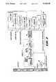
- FIG. 2shows, in block diagram form, apparatus for decoding matrices placed on articles according to the present invention.
- FIG. 3shows, in schematic form, the mapping of pixels on a CCD integrated circuit ("chip") to dots on a matrix according to the present invention in a one-to-one relationship.
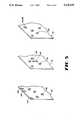
- FIG. 4shows, in schematic form, the mapping of pixels on a CCD chip to dots on a matrix according to the present invention in other than a one-to-one relationship.
- FIG. 5shows various schemes for reference marks and cues according to the present invention (other of which schemes are shown in other of the figures).
- FIG. 6shows a second embodiment of the matrix according to the present invention, which uses more than one information dot per row or column to represent a character in a particular symbology system.
- FIG. 1shows a preferred embodiment of a matrix 10 according to the present invention.
- Matrix 10conceptually is placed in the context of a frame 11 which contains a number of rows 12 and columns 14.
- FIG. 1uses a series of numerals to illustrate 1 through n rows and 1 through m columns in that reference frame 11.
- the numerals and the framepreferably are not used when the matrix is placed on an article according to the present invention, however.
- the matrix 10can include any desired number of rows, each of which may correspond to an alphanumeric character or other symbol, word, or concept, and any desired number of columns, each of which corresponds to a character or symbol, word or concept desired to conveyed in the matrix.
- characteras used in this document means an alphanumeric character or other symbol, word, concept, or any other tangible or intangible entity which is desired to be mapped onto a combination of one or more dots.
- sequence systemmeans the set of such characters, such as the English alphabet, the greek alphabet, numerals, an ASCII set, words in a conventional or artificial language, names and addresses in a list, organic chemical molecules, DNA sequences, concepts such as the different taste sensations which ma be experienced by the human tongue or colors in the spectrum, or any other tangible or intangible entities desired to be represented.
- the matrix 10may also be configured so that each column 14 corresponds to a character and each row 12 corresponds to the character desired to be conveyed in matrix 10.
- the dot 18 placed in column 1corresponds to the numeral "7" and the dot placed in column 2 corresponds to the numeral "2.”
- the mapping that occurthus corresponds to the vertical position of the dot in each column. Accordingly, a matrix having m columns for conveyance of m characters in a symbology system having n possible characters can convey n m different combinations. Matrices 10 according to the present invention are thus an efficient coding technique; for instance, a matrix of ten rows by ten columns can convey 10 billion difference combinations.
- the matrixcan, in a very small space, include m columns corresponding to the maximum number of characters anticipated in the longest name and address and 36 or more alphanumeric rows.
- More than one information dot 18can be included in a dimension (row 12, column 14 or any other array of spaces or intersections 13 which extends in at least one dimension).
- FIG. 6shows a scheme which uses two dots 18 in each column 14 as an example. According to this scheme, a dot 18 in one of the upper ten row-column interstices in the column 14 corresponds to a digit--the digit "1" in column 1, for instance. A dot 18 placed in the eleventh intersection 13 acts to "shift" the first ten interstices, to, for example, the first ten uncapitalized letters of the English alphabet. Thus, column two in FIG.
- Each row 12 or column 14 of matrix 10may obviously contain any number of dots 18 to represent a particular character set in a symbology system. According to this scheme, a column 14 of "q" intersections 13 could contain from one to "q" dots 18. The number of characters which could be represented by that column 14 would be, according to the binomial theorem:
- a matrix 10 with a dimensional array containing only 9 intersections 13could represent a character set of 512 characters, words, or concepts.
- present processing technologyprobably favors fewer numbers of dots 18, in order to allow imager 22 and computer 28 to process and use information rapidly, developments in computer hardware and software technology and in imaging capability will allow use of an increased number of dots 18 in a row 12 or column 14 and thus allow a far more compact and efficient mapping scheme as described above (or otherwise).
- Matrices 10are preferably interpreted using an imager having a large number of optical elements 23 or "pixels."
- One system for accomplishing this taskis shown schematically in FIG. 2.
- the imagerincludes a CCD chip.
- Such imagershave recently become available on a wide scale and inexpensive basis. For instance, Santa Barbara Instrument Group of Santa Barbara, Calif. presently provides their Model ST4 for approximately $1,000. Spectra Source Instruments of Aguora Hills, Calif., provides their series of LYNX imagers for a similar amount of money. Both of those imagers, which are suitable for amateur astronomy applications are capable of exposures or "integrations" from 1/100 seconds up to 5 to 15 minutes.
- these imagerscontain a very large number of optical elements 23, each of which senses and produces data corresponding to a very small increment of the entire field of view.
- the inexpensive imagers mentioned aboveuse a CCD chip that contains an array of 192 by 165 optical elements.
- the largest CCDs readily available as of the date of this documentinclude 2,048 by 2,048 pixels and sell for approximately $60,000.
- Imagers which are particularly suitable in the present inventioninclude the Videk Megaplus Solid State CCD camera, which employs a chip featuring 1320 horizontal by 1035 vertical pixels in approximately a half-square inch field.
- the Videk camerais provided by Videk, a Kodak Company, whose address is Canandiagua, N.Y.
- CCD imagerwhich has particular utility in the present invention, and which is sold with related interface and suitable computer capability as shown in FIG. 2, is provide under the EXPERT trademark by the Allen Bradley Company Industrial Control Group of Milwaukee, Wis.
- the EXPERT brand equipmentis typically used for industrial quality control applications.
- more than one optical element 23may be assigned to the area corresponding to a dot 18 in a matrix 10 according to the present invention.
- the matrix 10could be made sufficiently small or the lens system of the imager 22 could be adapted to allow one dot 18 to map onto the area covered by a pixel 23. Accordingly, for an imager 10 which employs a lens system to map a matrix 10 onto a one-half square inch CCD chip 26 in a one-to-one size relationship, as shown for instance in FIG.
- the dots in the matrixcould each be as small as 1.57 ⁇ 10 -5 square inch for a one-to-one dot 18 to pixel 23 correspondence.
- the Videk CCD chipcould similarly allow dots as small as 3.66 ⁇ 10 -7 square inch to be used.
- dots 18 and pixels 23creates ample room for error, however, and accordingly the present invention contemplates assigning a group of pixels 23 to cover the area on the CCD chip 26 corresponding to each dot 18 in the matrix 10.
- One possible mappingis shown in FIG. 4.
- dots 18such as the one shown in column 2, row 2, in FIG. 1, may be sensed by the CCD camera even if portions of them are missing, unlike in bar coding technology.
- the usercan typically adjust the sensitivity level necessary to product a positive signal from a pixel or group of pixel so that the imager records the presence of a dot when any desired reflectance ratio is reached. Accordingly, the present invention enjoys far more flexibility then bar coding applications which require a 70% reflectance ratio between dark and reflected areas.
- a typical imager 22 as shown in FIG. 2employs a CCD chip camera 24 containing a CCD chip 26.
- the camera 24provides analog image signals 28 to a analog to digital converter 30.
- the A/D converter 30receives information in serial form from charge-couple devices in the imager 22 and produces digital data 32 to be stored in frame buffers 34.
- a charge-coupled deviceincludes an array of light sensitive semiconductor elements. During an exposure, incoming photons cross a build-up of an electrical charge on each of the optical elements. In effect, the pixels accumulate tiny charges resulting from photons of light impacting electrons in the pixel's semiconductor strata.
- the pixelstransfer their charges, in an orderly fashion, one row at a time, to a number of shift registers. Simultaneously, and in a conceptual sense, information is conveyed from rows of pixels to the shift registers one row after the next to produce a serial stream of data which is then stored with appropriate position information, preferably in digital form.
- the imager 22 informationis provided to a computer interface 36 which conditions the digital information to allow for proper communication to a computer 38.
- Computer 38, interface 36 and imager 22may be of the type provided under the EXPERT trademark by Allen Bradley Industrial Control Group of Milwaukee, Wis. Such imagers, interfaces and computers are typically and conventionally used for product quality control, but lend themselves very well to the precise nature of encoding matrices according to the present invention.
- the computer 38may be linked by process control computer 40, or directly, to the line which controls positioning of the articles on which the matrices 10 appear, so that the matrices 10 appear before the imager 22 in an orderly and efficient manner.
- a light 42may be synchronized with the process control speed, if desired, to stroboscopically illuminate each matrix 10 as it appears before the imager 22.
- the imager 22through interface 36, provides data via a serial or parallel link to computer 38 in order to allow computer 38 to interpret the matrices 10. This task may be accomplished on a real time basis locally or over telephone lines or the information may be stored and provided after the matrices have been viewed by the imager 22.
- the information for each exposure of the imager 22includes information corresponding to a number of dots, and their distances, and angles relative to each other.
- reference marker 44may be considered as the conceptual focus of interpretation of data for each matrix 10.
- Reference marker 44may appear, as shown in FIG. 1, at the upper left of matrix 10, or it can appear anywhere else desired as shown in FIG. 5, for instance. It, as is the case with all the other dots and cues printed in the matrix, may be printed of any desired type and color of ink, including fluorescent inks which may be exposed only with a fluorescent light 42, but which will appear invisible to the viewer.
- a reference cue 46is also placed on the matrix.
- FIG. 1shows the cue near the upper right hand corner of the matrix 10, but other positions may be used, as shown, for instance, in FIG. 5.
- Reference cue 46may be a dot, line, square or any other one or two-dimensional mark of any desired shape. It may also be contiguous to and form a part of reference marker 44, or it may be a part of all of an information dot 18.
- Computer 38analyzes each set of data corresponding to a matrix 10 to analyze the distance between the reference marker 44 and each column dot, together with the angle between the column dot 18 and the reference cue 46 relative to reference marker 44.
- the computeranalyzes the data for matrix 10 to determine the distance "a" between reference mark 44 and column one's dot 48, together with angle ⁇ of column one's dot 48 to reference cue 46 relative to reference marker 44, as well as distance "b” from reference marker 44 from to column two's dot 50 and angle ⁇ between column two's dot 50 and reference cue 46 relative to reference marker 44.
- the computer 38thus produces vectors 19 corresponding to direction and distance of each column dot from reference marker 44. It may then compare such vectors 19 to information stored in a character database 52 relating to the symbology system used in the matrix 10 in order to identify the particular character in the symbology system corresponding to that vector 19.
- the computermay then store information for each character, and, if desired, compare such character information to information in that database or another relating to addressee information that includes names and addresses, or other information.
- the computer 38may calculate the angles between column dots 18 and reference cue 46 relative to reference marker 44 by analyzing data corresponding to one pixel 23 corresponding to a consistent position on each such marker or dot (such as, for instance, the right-hand top corner) where a group of pixels 23 corresponds to a dot in the matrix 10, so that angles and distances may be calculated consistently.
- the computer 38may calculate a "center of gravity,” assume when certain pixels 23 in a group sense presence of portions of a dot 18 that the center of that particular dot 18 is the position by which angles and distances are calculated, or employ any other desired means to consistently calculate angles and distances.
- Reference cue 46is preferably two dimensional.
- a two-dimensional reference cueis preferable since it may be analyzed by the computer 38 in three dimensions to account for the matrices 10 being nonparallel and/or rotated relative to the CCD chip 26 when read and for variations in distance of the matrices 10 from the chip 26.
- computer 38may calculate a distance "x" between the upper left tip of reference cue 46, and a distance "y” between reference marker 44 and lower right tip of reference cue 46.
- the computercould also analyze the angle between ray "x" and "y,” or other desired two-dimensional information as desired, including variations in shape and size of a single reference marker 44/cue 46 shape relative to a standard size and shape.
- the computer 38may accordingly determine distance scaling and attitudinal normalization information based on at least one distance and at least one angle, two or more distances, two or more angles, or a combination of distances and angles or shapes.
- the computer 38compares such information determined from data for a particular matrix 10 to a reference table in a database of attitude data 52 in order to produce vector attitude compensation information and/or distance scaling information to be applied to each vector corresponding to a column dot 18.
- the distancessuch as "a" and "b" in FIG. 1, may thus be scaled and normalized to correspond to the distances that would have been seen by the imager 22 had the matrix 10 actually been at a uniform distance, and in a uniform attitude relative to the imager 22 when viewed.
- the lens system of the imager 22, or other meanssuch as infrared or parallax means, for instance, may be used for distance scaling purposes.
- Matrix 10may be used for encoding and verifying various products in a small area, with minimum conspicuousness. Variations include printing the matrix with invisible fluorescent ink over text copy, in blank portions of direct mail pieces, coupons, tickets or similar matter, in a variety of colors such as those typically used for such matter, in a white fluorescent ink on a black background, in low density print, on low cost paper lacking minimum optical properties required for bar codes, on a translucent substrate appropriate for particular direct mail pieces, coupons, tickets or similar matter, or on a high gloss cast-coated premium grade stock appropriate for promotion of premium items, as immediate, nonlimiting examples.
- the matrices, interpretation devices and methods according to the present inventionmay be used for coupons, lottery tickets, security documents, envelopes, cards, labels, cartons, checks, containers, stocks, bonds and other applications requiring cross-reference identification. They may be used for auditing redemption coupons based on a mailing list of individuals or households, in order to analyze and develop demographic data, special interest mailing lists, sales analysis data and similar information, and are thus particularly well suited for direct mail applications. Similarly, the systems allow accurate, inexpensive and efficient verification of authenticity of lottery tickets, lotto tickets, security documents and similar articles. It also allows proper sorting and routing of mail envelopes, cards and postal items, by, for instance, activating or controlling distribution apparatus.
- Inventory control relating to specific products, manufacturing, accounting, sales data, or commercial package distributionforms yet another application for such systems, as does sorting of checks, stocks, bonds, and other documents. Other applications may be easily visualized.
- the matrixmay also obviously be decoded manually, if desired.
Landscapes
- Physics & Mathematics (AREA)
- Engineering & Computer Science (AREA)
- Electromagnetism (AREA)
- General Physics & Mathematics (AREA)
- Theoretical Computer Science (AREA)
- Health & Medical Sciences (AREA)
- General Health & Medical Sciences (AREA)
- Toxicology (AREA)
- Artificial Intelligence (AREA)
- Computer Vision & Pattern Recognition (AREA)
- Image Processing (AREA)
Abstract
Description
q!/0!(q-0)!+q!/1!(q-1)!+q!/2)!+ . . . q!/q!(q-q)!
Claims (19)
Priority Applications (1)
| Application Number | Priority Date | Filing Date | Title |
|---|---|---|---|
| US07/597,434US5128528A (en) | 1990-10-15 | 1990-10-15 | Matrix encoding devices and methods |
Applications Claiming Priority (1)
| Application Number | Priority Date | Filing Date | Title |
|---|---|---|---|
| US07/597,434US5128528A (en) | 1990-10-15 | 1990-10-15 | Matrix encoding devices and methods |
Publications (1)
| Publication Number | Publication Date |
|---|---|
| US5128528Atrue US5128528A (en) | 1992-07-07 |
Family
ID=24391485
Family Applications (1)
| Application Number | Title | Priority Date | Filing Date |
|---|---|---|---|
| US07/597,434Expired - Fee RelatedUS5128528A (en) | 1990-10-15 | 1990-10-15 | Matrix encoding devices and methods |
Country Status (1)
| Country | Link |
|---|---|
| US (1) | US5128528A (en) |
Cited By (54)
| Publication number | Priority date | Publication date | Assignee | Title |
|---|---|---|---|---|
| US5268580A (en)* | 1992-09-02 | 1993-12-07 | Ncr Corporation | Bar code enhancement system and method for vision scanners |
| US5288986A (en)* | 1992-09-17 | 1994-02-22 | Motorola, Inc. | Binary code matrix having data and parity bits |
| US5345089A (en)* | 1992-12-24 | 1994-09-06 | Pitney Bowes Inc. | System and method for optical scanner sensitivity adjustment |
| EP0665510A1 (en)* | 1993-12-30 | 1995-08-02 | TOMIOKA, Makoto | Two dimensional code sheet for processing data |
| DE4407603A1 (en)* | 1994-03-08 | 1995-09-14 | Ferrari Electronic Gmbh | Matrix array of sheet markings in headed columns for evaluation |
| WO1995026010A1 (en)* | 1994-03-18 | 1995-09-28 | Rolls-Royce Plc | A method and apparatus for identifying the orientation of a dot matrix code marking of an article |
| US5477012A (en)* | 1992-04-03 | 1995-12-19 | Sekendur; Oral F. | Optical position determination |
| US5536924A (en)* | 1994-06-07 | 1996-07-16 | Intermec Corporation | Method and apparatus for matrix symbology imager |
| US5616905A (en)* | 1994-02-24 | 1997-04-01 | Kabushiki Kaisha Tec | Two-dimensional code recognition method |
| US5652412A (en)* | 1994-07-11 | 1997-07-29 | Sia Technology Corp. | Pen and paper information recording system |
| WO1997043730A1 (en)* | 1996-05-10 | 1997-11-20 | Ioptics Incorporated | Alignment method and apparatus for retrieving information from a two-dimensional data array |
| EP0730250A4 (en)* | 1994-09-17 | 1998-05-13 | Hirokazu Yoshida | Recording card and recording method for two-dimensional code |
| US5900611A (en)* | 1997-06-30 | 1999-05-04 | Accu-Sort Systems, Inc. | Laser scanner with integral distance measurement system |
| US5984193A (en)* | 1998-03-04 | 1999-11-16 | Hewlett-Parkard Company | Printer media with bar code identification system |
| US6017496A (en) | 1995-06-07 | 2000-01-25 | Irori | Matrices with memories and uses thereof |
| EP0907139A3 (en)* | 1997-09-16 | 2000-02-23 | Eastman Kodak Company | Method and apparatus for reading invisibly encoded sound data on an object |
| EP0913814A3 (en)* | 1997-10-28 | 2000-02-23 | Eastman Kodak Company | System and method for imprinting and reading a sound message on a greeting card |
| US6032861A (en)* | 1995-01-03 | 2000-03-07 | Lemelson; Jerome H. | Method and apparatus for encoding and decoding bar codes with primary and secondary information and method of using such bar codes |
| WO2000012229A1 (en)* | 1998-08-26 | 2000-03-09 | Spectra Science Corporation | Methods and apparatus employing multi-spectral imaging for the remote identification and sorting of objects |
| EP0736835A3 (en)* | 1995-04-06 | 2000-05-10 | ROLLS-ROYCE plc | Process and apparatus for reading a dot matrix code marking on an article |
| US6136274A (en)* | 1996-10-07 | 2000-10-24 | Irori | Matrices with memories in automated drug discovery and units therefor |
| US6148249A (en)* | 1996-07-18 | 2000-11-14 | Newman; Paul Bernard | Identification and tracking of articles |
| EP0996083A3 (en)* | 1992-09-28 | 2000-12-20 | Olympus Optical Co., Ltd. | Information reproducing system for optically reading a dot code from a recording medium |
| US6329139B1 (en) | 1995-04-25 | 2001-12-11 | Discovery Partners International | Automated sorting system for matrices with memory |
| US6330974B1 (en) | 1996-03-29 | 2001-12-18 | Intermec Ip Corp. | High resolution laser imager for low contrast symbology |
| US6441380B1 (en) | 1999-10-13 | 2002-08-27 | Spectra Systems Corporation | Coding and authentication by phase measurement modulation response and spectral emission |
| US6494373B2 (en)* | 2001-01-10 | 2002-12-17 | Yokogawa Electric Corporation | Biochip reader |
| US20030076268A1 (en)* | 2001-10-22 | 2003-04-24 | Filtronic Lk Oy | Internal multiband antenna |
| US20030121980A1 (en)* | 1995-01-03 | 2003-07-03 | Lemelson Jerome H. | Method and apparatus for encoding and decoding bar codes with primary and secondary information and method of using such bar codes |
| US6633370B2 (en) | 2000-03-07 | 2003-10-14 | Spectra Science Corporation | Quantum dots, semiconductor nanocrystals and semiconductor particles used as fluorescent coding elements |
| US6666376B1 (en) | 1999-05-28 | 2003-12-23 | Anoto Ab | Calendar |
| US20040004123A1 (en)* | 1999-05-24 | 2004-01-08 | Sadler John W. | Apparatus and method for scanning a surface |
| US20040020993A1 (en)* | 2001-12-28 | 2004-02-05 | Green Larry R. | Method for luminescent identification and calibration |
| US20040060987A1 (en)* | 2002-05-07 | 2004-04-01 | Green Larry R. | Digital image analysis method for enhanced and optimized signals in fluorophore detection |
| US6767733B1 (en) | 2001-10-10 | 2004-07-27 | Pritest, Inc. | Portable biosensor apparatus with controlled flow |
| US20040182925A1 (en)* | 2003-03-04 | 2004-09-23 | Duane Anderson | Item tracking and processing systems and methods |
| US20040195320A1 (en)* | 2003-03-04 | 2004-10-07 | United Parcel Service Of America, Inc. | System for projecting a handling instruction onto a moving item or parcel |
| US6861251B2 (en) | 2003-02-24 | 2005-03-01 | Pritest, Inc. | Translucent solid matrix assay device for microarray analysis |
| US6874639B2 (en) | 1999-08-23 | 2005-04-05 | Spectra Systems Corporation | Methods and apparatus employing multi-spectral imaging for the remote identification and sorting of objects |
| US6878896B2 (en) | 2002-07-24 | 2005-04-12 | United Parcel Service Of America, Inc. | Synchronous semi-automatic parallel sorting |
| US20060007304A1 (en)* | 2004-07-09 | 2006-01-12 | Duane Anderson | System and method for displaying item information |
| US20060216869A1 (en)* | 2005-03-22 | 2006-09-28 | Asml Netherlands B.V. | Lithographic apparatus, device manufacturing method, code reading device and substrate |
| WO2007004994A1 (en)* | 2005-07-01 | 2007-01-11 | Grid Ip Pte. Ltd. | Dot pattern |
| US20070172123A1 (en)* | 2006-01-25 | 2007-07-26 | Fuji Xerox Co., Ltd. | Image processing apparatus, image processing method and computer readable medium |
| US20080194016A1 (en)* | 2005-10-10 | 2008-08-14 | Kusters Ronald Johannes Wilhel | Tissue Container, and Devicer and Method For Providing Such a Tissue Container With Data |
| US20080252066A1 (en)* | 2007-04-12 | 2008-10-16 | Honeywell, Inc. | Method and system for creating and reading multi-color co-planar emissive indicia using printable dyes and pigments |
| US20100149715A1 (en)* | 2008-12-11 | 2010-06-17 | Harry George Yaworski | High Amperage Surge Arrestors |
| US8038538B2 (en) | 2004-06-04 | 2011-10-18 | Mattel, Inc. | Electronic device for enhancing an interactive experience with a tangible medium of expression |
| US20110303748A1 (en)* | 2010-06-11 | 2011-12-15 | Dereje Teferi Lemma | Method and Apparatus for Encoding and Reading Optical Machine-Readable Data Codes |
| US9372548B2 (en) | 2002-09-26 | 2016-06-21 | Kenji Yoshida | Information reproduction/I/O method using dot pattern, information reproduction device, mobile information I/O device, and electronic toy using dot pattern |
| US9582701B2 (en) | 2005-04-28 | 2017-02-28 | Kenji Yoshida | Information input/output method using dot pattern |
| EP1803110B1 (en) | 2004-10-11 | 2018-12-05 | Synovation B.V. | Tissue container, and method for arranging data on such a tissue container |
| US10471478B2 (en) | 2017-04-28 | 2019-11-12 | United Parcel Service Of America, Inc. | Conveyor belt assembly for identifying an asset sort location and methods of utilizing the same |
| WO2024242620A1 (en)* | 2023-05-19 | 2024-11-28 | Aires Investment Holdings Private Limited | Two-dimensional code and method and system for generating and reading thereof |
Citations (42)
| Publication number | Priority date | Publication date | Assignee | Title |
|---|---|---|---|---|
| GB155982A (en)* | 1920-06-24 | 1921-01-06 | Seth Appleby | Improvements in or relating to the furnaces of steam boilers and the like |
| US2000403A (en)* | 1927-04-07 | 1935-05-07 | Ibm | Method of and means for analyzing record cards |
| US2612994A (en)* | 1949-10-20 | 1952-10-07 | Norman J Woodland | Classifying apparatus and method |
| US2925586A (en)* | 1953-04-29 | 1960-02-16 | Levy Maurice Moise | Method of, and apparatus for, electronically interpreting a pattern code |
| US3309667A (en)* | 1960-07-26 | 1967-03-14 | Bull Sa Machines | Character identifying arrangement |
| US3409760A (en)* | 1966-12-14 | 1968-11-05 | Monarch Marking Systems Inc | Machine readable merchandise tag |
| US3474230A (en)* | 1967-06-19 | 1969-10-21 | Addressograph Multigraph | Parity check multiple scan scanning system for machine read code characters |
| US3492660A (en)* | 1969-02-25 | 1970-01-27 | American Cyanamid Co | Bar code encoding and information retrieval |
| US3506783A (en)* | 1966-06-17 | 1970-04-14 | Int Standard Electric Corp | Key material generator |
| US3529133A (en)* | 1965-06-30 | 1970-09-15 | Honeywell Inc | Encoding system |
| US3543007A (en)* | 1962-10-10 | 1970-11-24 | Westinghouse Air Brake Co | Automatic car identification system |
| US3643068A (en)* | 1969-03-12 | 1972-02-15 | Spartanics | Random oriented decoder for label decoding |
| US3760161A (en)* | 1971-05-19 | 1973-09-18 | American Cyanamid Co | Method and apparatus for automatically retrieving information from a succession of luminescent coded documents with means for segregating documents according to their characteristics |
| US3774758A (en)* | 1971-02-24 | 1973-11-27 | H Sternberg | Method and aid for the automated sorting of mail by zip code |
| US3792236A (en)* | 1973-03-26 | 1974-02-12 | Monarch Marking Systems Inc | Record reading system |
| US3811033A (en)* | 1971-06-29 | 1974-05-14 | Monarch Marking Systems Inc | Coded record interpreting system |
| US3870865A (en)* | 1973-07-05 | 1975-03-11 | Cummins Allison Corp | Method and apparatus for optical reading of recorded data |
| US3894756A (en)* | 1971-10-18 | 1975-07-15 | Optronics Int | Identification card having a reference beam coded hologram |
| US3925611A (en)* | 1974-08-12 | 1975-12-09 | Bell Telephone Labor Inc | Combined scrambler-encoder for multilevel digital data |
| US4034210A (en)* | 1975-09-19 | 1977-07-05 | Dynetics Engineering Corporation | Credit card carriers and methods of manufacture |
| US4159468A (en)* | 1977-11-17 | 1979-06-26 | Burroughs Corporation | Communications line authentication device |
| US4163570A (en)* | 1976-12-21 | 1979-08-07 | Lgz Landis & Gyr Zug Ag | Optically coded document and method of making same |
| US4180284A (en)* | 1977-11-09 | 1979-12-25 | Ashley James E | Tag for identifying luggage and method of using same |
| US4211918A (en)* | 1977-06-21 | 1980-07-08 | Lgz Landis & Gyr Zug Ag | Method and device for identifying documents |
| US4239261A (en)* | 1978-08-24 | 1980-12-16 | Richardson Robert H | Micro-marking label and apparatus |
| US4286146A (en)* | 1976-02-06 | 1981-08-25 | Hitachi, Ltd. | Coded label and code reader for the coded label |
| US4300123A (en)* | 1979-01-02 | 1981-11-10 | Westinghouse Electric Corp. | Optical reading system |
| EP0081316A2 (en)* | 1981-11-27 | 1983-06-15 | Unisys Corporation | Recognition logic circuit for bar code reader system |
| US4489318A (en)* | 1980-06-23 | 1984-12-18 | Light Signatures, Inc. | Non-counterfeitable document system |
| US4591704A (en)* | 1983-04-18 | 1986-05-27 | Engineered Systems, Inc. | Data scrambling system and method |
| US4614366A (en)* | 1983-11-18 | 1986-09-30 | Exactident, Inc. | Nail identification wafer |
| US4630844A (en)* | 1985-07-24 | 1986-12-23 | Troy Seymour L | Two-step bank draft |
| US4637634A (en)* | 1985-07-24 | 1987-01-20 | Troy Seymour L | Two-part bank draft |
| US4660221A (en)* | 1983-07-18 | 1987-04-21 | Pitney Bowes Inc. | System for printing encrypted messages with bar-code representation |
| US4736109A (en)* | 1986-08-13 | 1988-04-05 | Bally Manufacturing Company | Coded document and document reading system |
| US4748679A (en)* | 1986-07-25 | 1988-05-31 | Light Signatures, Inc. | Weighted-pixel characteristic sensing system |
| US4752675A (en)* | 1985-12-23 | 1988-06-21 | Zetmeir Karl D | Method of collecting response data from direct mail advertising |
| US4760247A (en)* | 1986-04-04 | 1988-07-26 | Bally Manufacturing Company | Optical card reader utilizing area image processing |
| US4814589A (en)* | 1986-04-18 | 1989-03-21 | Leonard Storch | Information transfer and use, particularly with respect to objects such as gambling chips |
| US4924078A (en)* | 1987-11-25 | 1990-05-08 | Sant Anselmo Carl | Identification symbol, system and method |
| US4939354A (en)* | 1988-05-05 | 1990-07-03 | Datacode International, Inc. | Dynamically variable machine readable binary code and method for reading and producing thereof |
| US4972475A (en)* | 1987-02-10 | 1990-11-20 | Veritec Inc. | Authenticating pseudo-random code and apparatus |
- 1990
- 1990-10-15USUS07/597,434patent/US5128528A/ennot_activeExpired - Fee Related
Patent Citations (43)
| Publication number | Priority date | Publication date | Assignee | Title |
|---|---|---|---|---|
| GB155982A (en)* | 1920-06-24 | 1921-01-06 | Seth Appleby | Improvements in or relating to the furnaces of steam boilers and the like |
| US2000403A (en)* | 1927-04-07 | 1935-05-07 | Ibm | Method of and means for analyzing record cards |
| US2612994A (en)* | 1949-10-20 | 1952-10-07 | Norman J Woodland | Classifying apparatus and method |
| US2925586A (en)* | 1953-04-29 | 1960-02-16 | Levy Maurice Moise | Method of, and apparatus for, electronically interpreting a pattern code |
| US3309667A (en)* | 1960-07-26 | 1967-03-14 | Bull Sa Machines | Character identifying arrangement |
| US3543007A (en)* | 1962-10-10 | 1970-11-24 | Westinghouse Air Brake Co | Automatic car identification system |
| US3529133A (en)* | 1965-06-30 | 1970-09-15 | Honeywell Inc | Encoding system |
| US3506783A (en)* | 1966-06-17 | 1970-04-14 | Int Standard Electric Corp | Key material generator |
| US3409760A (en)* | 1966-12-14 | 1968-11-05 | Monarch Marking Systems Inc | Machine readable merchandise tag |
| US3474230A (en)* | 1967-06-19 | 1969-10-21 | Addressograph Multigraph | Parity check multiple scan scanning system for machine read code characters |
| US3492660A (en)* | 1969-02-25 | 1970-01-27 | American Cyanamid Co | Bar code encoding and information retrieval |
| US3643068A (en)* | 1969-03-12 | 1972-02-15 | Spartanics | Random oriented decoder for label decoding |
| US3774758A (en)* | 1971-02-24 | 1973-11-27 | H Sternberg | Method and aid for the automated sorting of mail by zip code |
| US3760161A (en)* | 1971-05-19 | 1973-09-18 | American Cyanamid Co | Method and apparatus for automatically retrieving information from a succession of luminescent coded documents with means for segregating documents according to their characteristics |
| US3811033A (en)* | 1971-06-29 | 1974-05-14 | Monarch Marking Systems Inc | Coded record interpreting system |
| US3894756A (en)* | 1971-10-18 | 1975-07-15 | Optronics Int | Identification card having a reference beam coded hologram |
| US3792236A (en)* | 1973-03-26 | 1974-02-12 | Monarch Marking Systems Inc | Record reading system |
| US3870865A (en)* | 1973-07-05 | 1975-03-11 | Cummins Allison Corp | Method and apparatus for optical reading of recorded data |
| US3925611A (en)* | 1974-08-12 | 1975-12-09 | Bell Telephone Labor Inc | Combined scrambler-encoder for multilevel digital data |
| US4034210A (en)* | 1975-09-19 | 1977-07-05 | Dynetics Engineering Corporation | Credit card carriers and methods of manufacture |
| US4034210B1 (en)* | 1975-09-19 | 1984-02-07 | ||
| US4286146A (en)* | 1976-02-06 | 1981-08-25 | Hitachi, Ltd. | Coded label and code reader for the coded label |
| US4163570A (en)* | 1976-12-21 | 1979-08-07 | Lgz Landis & Gyr Zug Ag | Optically coded document and method of making same |
| US4211918A (en)* | 1977-06-21 | 1980-07-08 | Lgz Landis & Gyr Zug Ag | Method and device for identifying documents |
| US4180284A (en)* | 1977-11-09 | 1979-12-25 | Ashley James E | Tag for identifying luggage and method of using same |
| US4159468A (en)* | 1977-11-17 | 1979-06-26 | Burroughs Corporation | Communications line authentication device |
| US4239261A (en)* | 1978-08-24 | 1980-12-16 | Richardson Robert H | Micro-marking label and apparatus |
| US4300123A (en)* | 1979-01-02 | 1981-11-10 | Westinghouse Electric Corp. | Optical reading system |
| US4489318A (en)* | 1980-06-23 | 1984-12-18 | Light Signatures, Inc. | Non-counterfeitable document system |
| EP0081316A2 (en)* | 1981-11-27 | 1983-06-15 | Unisys Corporation | Recognition logic circuit for bar code reader system |
| US4591704A (en)* | 1983-04-18 | 1986-05-27 | Engineered Systems, Inc. | Data scrambling system and method |
| US4660221A (en)* | 1983-07-18 | 1987-04-21 | Pitney Bowes Inc. | System for printing encrypted messages with bar-code representation |
| US4614366A (en)* | 1983-11-18 | 1986-09-30 | Exactident, Inc. | Nail identification wafer |
| US4630844A (en)* | 1985-07-24 | 1986-12-23 | Troy Seymour L | Two-step bank draft |
| US4637634A (en)* | 1985-07-24 | 1987-01-20 | Troy Seymour L | Two-part bank draft |
| US4752675A (en)* | 1985-12-23 | 1988-06-21 | Zetmeir Karl D | Method of collecting response data from direct mail advertising |
| US4760247A (en)* | 1986-04-04 | 1988-07-26 | Bally Manufacturing Company | Optical card reader utilizing area image processing |
| US4814589A (en)* | 1986-04-18 | 1989-03-21 | Leonard Storch | Information transfer and use, particularly with respect to objects such as gambling chips |
| US4748679A (en)* | 1986-07-25 | 1988-05-31 | Light Signatures, Inc. | Weighted-pixel characteristic sensing system |
| US4736109A (en)* | 1986-08-13 | 1988-04-05 | Bally Manufacturing Company | Coded document and document reading system |
| US4972475A (en)* | 1987-02-10 | 1990-11-20 | Veritec Inc. | Authenticating pseudo-random code and apparatus |
| US4924078A (en)* | 1987-11-25 | 1990-05-08 | Sant Anselmo Carl | Identification symbol, system and method |
| US4939354A (en)* | 1988-05-05 | 1990-07-03 | Datacode International, Inc. | Dynamically variable machine readable binary code and method for reading and producing thereof |
Non-Patent Citations (6)
| Title |
|---|
| Chibnik, Michael, "CCD Cameras: Digital Astrophotography is Here," Astronomy, Oct. 1990, cover sheet and pp. 66-73. |
| Chibnik, Michael, CCD Cameras: Digital Astrophotography is Here, Astronomy, Oct. 1990, cover sheet and pp. 66 73.* |
| Harmon, Craig K. and Russ Adams, Reading Between the Lines: An Introduction To Bar Code Technology, Helmers Publishing, Inc., pp. 16 17, 36 37, 238 239, 260 263, 266 267.* |
| Harmon, Craig K. and Russ Adams, Reading Between the Lines: An Introduction To Bar Code Technology, Helmers Publishing, Inc., pp. 16-17, 36-37, 238-239, 260-263, 266-267. |
| The brochure entitled "Expert PVS 2805 Programmable Vision System," Publication 2805-1.3-Feb. 1988 (29 pages). |
| The brochure entitled Expert PVS 2805 Programmable Vision System, Publication 2805 1.3 Feb. 1988 (29 pages).* |
Cited By (87)
| Publication number | Priority date | Publication date | Assignee | Title |
|---|---|---|---|---|
| US5477012A (en)* | 1992-04-03 | 1995-12-19 | Sekendur; Oral F. | Optical position determination |
| US5268580A (en)* | 1992-09-02 | 1993-12-07 | Ncr Corporation | Bar code enhancement system and method for vision scanners |
| US5288986A (en)* | 1992-09-17 | 1994-02-22 | Motorola, Inc. | Binary code matrix having data and parity bits |
| EP0996083A3 (en)* | 1992-09-28 | 2000-12-20 | Olympus Optical Co., Ltd. | Information reproducing system for optically reading a dot code from a recording medium |
| US6622276B2 (en) | 1992-09-28 | 2003-09-16 | Olympus Optical Co., Ltd. | Recording medium, information reproducing apparatus and information reproducing method |
| US6460155B1 (en) | 1992-09-28 | 2002-10-01 | Olympus Optical Co., Ltd. | Information reproducing system capable of manually reading an optically readable code and repeatedly reproducing voice information included in the code |
| US5345089A (en)* | 1992-12-24 | 1994-09-06 | Pitney Bowes Inc. | System and method for optical scanner sensitivity adjustment |
| EP0665510A1 (en)* | 1993-12-30 | 1995-08-02 | TOMIOKA, Makoto | Two dimensional code sheet for processing data |
| US5616905A (en)* | 1994-02-24 | 1997-04-01 | Kabushiki Kaisha Tec | Two-dimensional code recognition method |
| DE4407603A1 (en)* | 1994-03-08 | 1995-09-14 | Ferrari Electronic Gmbh | Matrix array of sheet markings in headed columns for evaluation |
| US5736723A (en)* | 1994-03-18 | 1998-04-07 | Rolls-Polce Plc | Method and apparatus for identifying the orientation of a dot matrix code marking of an article |
| WO1995026010A1 (en)* | 1994-03-18 | 1995-09-28 | Rolls-Royce Plc | A method and apparatus for identifying the orientation of a dot matrix code marking of an article |
| US5536924A (en)* | 1994-06-07 | 1996-07-16 | Intermec Corporation | Method and apparatus for matrix symbology imager |
| US5652412A (en)* | 1994-07-11 | 1997-07-29 | Sia Technology Corp. | Pen and paper information recording system |
| EP0730250A4 (en)* | 1994-09-17 | 1998-05-13 | Hirokazu Yoshida | Recording card and recording method for two-dimensional code |
| US6991164B2 (en) | 1995-01-03 | 2006-01-31 | Lemelson Medical, Education & Research Foundation, Limited Partnership | Method and apparatus for encoding and decoding bar codes with primary and secondary information and method of using such bar codes |
| US20030121980A1 (en)* | 1995-01-03 | 2003-07-03 | Lemelson Jerome H. | Method and apparatus for encoding and decoding bar codes with primary and secondary information and method of using such bar codes |
| US6032861A (en)* | 1995-01-03 | 2000-03-07 | Lemelson; Jerome H. | Method and apparatus for encoding and decoding bar codes with primary and secondary information and method of using such bar codes |
| EP0736835A3 (en)* | 1995-04-06 | 2000-05-10 | ROLLS-ROYCE plc | Process and apparatus for reading a dot matrix code marking on an article |
| US6329139B1 (en) | 1995-04-25 | 2001-12-11 | Discovery Partners International | Automated sorting system for matrices with memory |
| US6017496A (en) | 1995-06-07 | 2000-01-25 | Irori | Matrices with memories and uses thereof |
| US6330974B1 (en) | 1996-03-29 | 2001-12-18 | Intermec Ip Corp. | High resolution laser imager for low contrast symbology |
| AU712943B2 (en)* | 1996-05-10 | 1999-11-18 | Ioptics Incorporated | Alignment method and apparatus for retrieving information from a two-dimensional data array |
| WO1997043730A1 (en)* | 1996-05-10 | 1997-11-20 | Ioptics Incorporated | Alignment method and apparatus for retrieving information from a two-dimensional data array |
| US6148249A (en)* | 1996-07-18 | 2000-11-14 | Newman; Paul Bernard | Identification and tracking of articles |
| US6136274A (en)* | 1996-10-07 | 2000-10-24 | Irori | Matrices with memories in automated drug discovery and units therefor |
| US5900611A (en)* | 1997-06-30 | 1999-05-04 | Accu-Sort Systems, Inc. | Laser scanner with integral distance measurement system |
| EP0907139A3 (en)* | 1997-09-16 | 2000-02-23 | Eastman Kodak Company | Method and apparatus for reading invisibly encoded sound data on an object |
| EP0913814A3 (en)* | 1997-10-28 | 2000-02-23 | Eastman Kodak Company | System and method for imprinting and reading a sound message on a greeting card |
| US6441921B1 (en) | 1997-10-28 | 2002-08-27 | Eastman Kodak Company | System and method for imprinting and reading a sound message on a greeting card |
| US5984193A (en)* | 1998-03-04 | 1999-11-16 | Hewlett-Parkard Company | Printer media with bar code identification system |
| US6488155B2 (en) | 1998-08-26 | 2002-12-03 | Spectra Systems Corporation | Methods and apparatus employing multi-spectral imaging for the remote identification and sorting of objects |
| AU753748B2 (en)* | 1998-08-26 | 2002-10-24 | Spectra Science Corporation | Methods and apparatus employing multi-spectral imaging for the remote identification and sorting of objects |
| WO2000012229A1 (en)* | 1998-08-26 | 2000-03-09 | Spectra Science Corporation | Methods and apparatus employing multi-spectral imaging for the remote identification and sorting of objects |
| US6578712B2 (en) | 1998-08-26 | 2003-06-17 | Spectra Science Corporation | Methods and apparatus employing multi-spectral imaging for the remote identification and sorting of objects |
| US6296189B1 (en) | 1998-08-26 | 2001-10-02 | Spectra Science Corporation. | Methods and apparatus employing multi-spectral imaging for the remote identification and sorting of objects |
| US6902112B2 (en)* | 1999-05-24 | 2005-06-07 | Agilent Technologies, Inc. | Apparatus and method for scanning a surface |
| US20040004123A1 (en)* | 1999-05-24 | 2004-01-08 | Sadler John W. | Apparatus and method for scanning a surface |
| US6666376B1 (en) | 1999-05-28 | 2003-12-23 | Anoto Ab | Calendar |
| US6874639B2 (en) | 1999-08-23 | 2005-04-05 | Spectra Systems Corporation | Methods and apparatus employing multi-spectral imaging for the remote identification and sorting of objects |
| US6441380B1 (en) | 1999-10-13 | 2002-08-27 | Spectra Systems Corporation | Coding and authentication by phase measurement modulation response and spectral emission |
| US6633370B2 (en) | 2000-03-07 | 2003-10-14 | Spectra Science Corporation | Quantum dots, semiconductor nanocrystals and semiconductor particles used as fluorescent coding elements |
| US6494373B2 (en)* | 2001-01-10 | 2002-12-17 | Yokogawa Electric Corporation | Biochip reader |
| US6767733B1 (en) | 2001-10-10 | 2004-07-27 | Pritest, Inc. | Portable biosensor apparatus with controlled flow |
| US20030076268A1 (en)* | 2001-10-22 | 2003-04-24 | Filtronic Lk Oy | Internal multiband antenna |
| US20040020993A1 (en)* | 2001-12-28 | 2004-02-05 | Green Larry R. | Method for luminescent identification and calibration |
| US20040060987A1 (en)* | 2002-05-07 | 2004-04-01 | Green Larry R. | Digital image analysis method for enhanced and optimized signals in fluorophore detection |
| US6878896B2 (en) | 2002-07-24 | 2005-04-12 | United Parcel Service Of America, Inc. | Synchronous semi-automatic parallel sorting |
| US10192154B2 (en) | 2002-09-26 | 2019-01-29 | Kenji Yoshida | Information reproduction/I/O method using dot pattern, information reproduction device, mobile information I/O device, and electronic toy using dot pattern |
| US9372548B2 (en) | 2002-09-26 | 2016-06-21 | Kenji Yoshida | Information reproduction/I/O method using dot pattern, information reproduction device, mobile information I/O device, and electronic toy using dot pattern |
| US9773140B2 (en) | 2002-09-26 | 2017-09-26 | Kenji Yoshida | Information reproduction/I/O method using dot pattern, information reproduction device, mobile information I/O device, and electronic toy using dot pattern |
| US10339431B2 (en) | 2002-09-26 | 2019-07-02 | Kenji Yoshida | Information reproduction/I/O method using dot pattern, information reproduction device, mobile information I/O device, and electronic toy using dot pattern |
| US9946964B2 (en) | 2002-09-26 | 2018-04-17 | Kenji Yoshida | Information reproducing method, information inputting/outputting method, information reproducing device, portable information inputting/outputting device and electronic toy using dot pattern |
| US9984317B2 (en) | 2002-09-26 | 2018-05-29 | Kenji Yoshida | Information reproducing method, information inputting / outputting method, information reproducing device, portable information inputting/ outputting device and electronic toy using dot pattern |
| US6861251B2 (en) | 2003-02-24 | 2005-03-01 | Pritest, Inc. | Translucent solid matrix assay device for microarray analysis |
| US20060159306A1 (en)* | 2003-03-04 | 2006-07-20 | United Parcel Service Of America, Inc. | Item tracking and processing systems and methods |
| US7090134B2 (en) | 2003-03-04 | 2006-08-15 | United Parcel Service Of America, Inc. | System for projecting a handling instruction onto a moving item or parcel |
| US20060159307A1 (en)* | 2003-03-04 | 2006-07-20 | United Parcel Service Of America, Inc. | Item tracking and processing systems and methods |
| US7201316B2 (en) | 2003-03-04 | 2007-04-10 | United Parcel Service Of America, Inc. | Item tracking and processing systems and methods |
| US7063256B2 (en) | 2003-03-04 | 2006-06-20 | United Parcel Service Of America | Item tracking and processing systems and methods |
| US7377429B2 (en) | 2003-03-04 | 2008-05-27 | United Parcel Service Of America, Inc. | Item tracking and processing systems and methods |
| US20040182925A1 (en)* | 2003-03-04 | 2004-09-23 | Duane Anderson | Item tracking and processing systems and methods |
| US20040195320A1 (en)* | 2003-03-04 | 2004-10-07 | United Parcel Service Of America, Inc. | System for projecting a handling instruction onto a moving item or parcel |
| US8038538B2 (en) | 2004-06-04 | 2011-10-18 | Mattel, Inc. | Electronic device for enhancing an interactive experience with a tangible medium of expression |
| US20060007304A1 (en)* | 2004-07-09 | 2006-01-12 | Duane Anderson | System and method for displaying item information |
| US7561717B2 (en) | 2004-07-09 | 2009-07-14 | United Parcel Service Of America, Inc. | System and method for displaying item information |
| EP1803110B1 (en) | 2004-10-11 | 2018-12-05 | Synovation B.V. | Tissue container, and method for arranging data on such a tissue container |
| US20060216869A1 (en)* | 2005-03-22 | 2006-09-28 | Asml Netherlands B.V. | Lithographic apparatus, device manufacturing method, code reading device and substrate |
| US9582701B2 (en) | 2005-04-28 | 2017-02-28 | Kenji Yoshida | Information input/output method using dot pattern |
| EP2439677A3 (en)* | 2005-07-01 | 2012-06-27 | Grid IP Pte. Ltd. | Dot pattern reading and generating devices |
| WO2007004994A1 (en)* | 2005-07-01 | 2007-01-11 | Grid Ip Pte. Ltd. | Dot pattern |
| RU2439699C2 (en)* | 2005-07-01 | 2012-01-10 | Грид Айпи Пти. Лтд. | Dot structure |
| US8430328B2 (en) | 2005-07-01 | 2013-04-30 | Grid Ip Pte. Ltd | Dot pattern |
| US20100133351A1 (en)* | 2005-07-01 | 2010-06-03 | Grid Ip Pte. Ltd | Dot pattern |
| US9400951B2 (en) | 2005-07-01 | 2016-07-26 | Grid Ip Pte Ltd | Dot pattern |
| US20080194016A1 (en)* | 2005-10-10 | 2008-08-14 | Kusters Ronald Johannes Wilhel | Tissue Container, and Devicer and Method For Providing Such a Tissue Container With Data |
| US20070172123A1 (en)* | 2006-01-25 | 2007-07-26 | Fuji Xerox Co., Ltd. | Image processing apparatus, image processing method and computer readable medium |
| US20080252066A1 (en)* | 2007-04-12 | 2008-10-16 | Honeywell, Inc. | Method and system for creating and reading multi-color co-planar emissive indicia using printable dyes and pigments |
| US8905313B2 (en) | 2007-04-12 | 2014-12-09 | Honeywell International Inc. | Method and system for creating and reading multi-color co-planar emissive indicia using printable dyes and pigments |
| US20100149715A1 (en)* | 2008-12-11 | 2010-06-17 | Harry George Yaworski | High Amperage Surge Arrestors |
| US8757490B2 (en)* | 2010-06-11 | 2014-06-24 | Josef Bigun | Method and apparatus for encoding and reading optical machine-readable data codes |
| US20110303748A1 (en)* | 2010-06-11 | 2011-12-15 | Dereje Teferi Lemma | Method and Apparatus for Encoding and Reading Optical Machine-Readable Data Codes |
| US10471478B2 (en) | 2017-04-28 | 2019-11-12 | United Parcel Service Of America, Inc. | Conveyor belt assembly for identifying an asset sort location and methods of utilizing the same |
| US11090689B2 (en) | 2017-04-28 | 2021-08-17 | United Parcel Service Of America, Inc. | Conveyor belt assembly for identifying an asset sort location and methods of utilizing the same |
| US11858010B2 (en) | 2017-04-28 | 2024-01-02 | United Parcel Service Of America, Inc. | Conveyor belt assembly for identifying an asset sort location and methods of utilizing the same |
| WO2024242620A1 (en)* | 2023-05-19 | 2024-11-28 | Aires Investment Holdings Private Limited | Two-dimensional code and method and system for generating and reading thereof |
| US12361248B2 (en) | 2023-05-19 | 2025-07-15 | Aires Investment Holdings Private Limited | Two-dimensional code and method and system for generating and reading thereof |
Similar Documents
| Publication | Publication Date | Title |
|---|---|---|
| US5128528A (en) | Matrix encoding devices and methods | |
| US6325420B1 (en) | Method for embedding non-intrusive encoded data in printed matter and system for reading same | |
| US4889367A (en) | Multi-readable information system | |
| US6457651B2 (en) | Dual mode, dual information, document bar coding and reading system | |
| CN100433038C (en) | Method for reading a symbol having encoded information | |
| US7337969B2 (en) | Method for improving the readability of composite images | |
| US5607187A (en) | Method of identifying a plurality of labels having data fields within a machine readable border | |
| US6236735B1 (en) | Two camera system for locating and storing indicia on conveyed items | |
| CN100483313C (en) | Method and device for processing of information | |
| CA2454380C (en) | Method for improving the readability of composite images | |
| US6974080B1 (en) | Lenticular bar code image | |
| US4317030A (en) | Mailing package for facilitating automatic sorting of mail | |
| US6892949B2 (en) | Low visual impact labeling method and system | |
| US20020176114A1 (en) | Method for utilizing a fragile watermark for enhanced security | |
| US6533385B1 (en) | Method for determining a printer's signature and the number of dots per inch printed in a document to provide proof that the printer printed a particular document | |
| CN101602296A (en) | Establishment can be verified the device of printing article and verifying them subsequently | |
| US20030107759A1 (en) | Apparatus and method for printing two-dimensional barcode and articles incorporating such barcode | |
| US20050194444A1 (en) | System for encoding information using colors | |
| AU2864492A (en) | Identification system | |
| KR20010024878A (en) | Method and system for identifying one or more objects | |
| US20140363081A1 (en) | Machine reading of printed data | |
| CN1110750C (en) | Pixel splitting to improve bar code readability | |
| KR100784577B1 (en) | Credit card purchase | |
| EP1035515A2 (en) | Postal stamp and method of vertying the validity thereof | |
| US6612684B2 (en) | Method for determining a printer's signature to provide proof that the printer printed a particular document |
Legal Events
| Date | Code | Title | Description |
|---|---|---|---|
| AS | Assignment | Owner name:DITTLER BROTHERS, INCORPORATED, A CORP. OF GA, GEO Free format text:ASSIGNMENT OF ASSIGNORS INTEREST.;ASSIGNOR:HENINGER, BYRNE E.;REEL/FRAME:005482/0139 Effective date:19901012 | |
| CC | Certificate of correction | ||
| AS | Assignment | Owner name:CIT GROUP/BUSINESS CREDIT, INC., THE, GEORGIA Free format text:PATENT COLLATERAL ASSIGNMENT AND SECURITY AGREEMENT;ASSIGNOR:DITTLER BROTHERS, INCORPORATED;REEL/FRAME:007677/0758 Effective date:19951006 | |
| FEPP | Fee payment procedure | Free format text:PAYOR NUMBER ASSIGNED (ORIGINAL EVENT CODE: ASPN); ENTITY STATUS OF PATENT OWNER: LARGE ENTITY | |
| FPAY | Fee payment | Year of fee payment:4 | |
| FEPP | Fee payment procedure | Free format text:PAYOR NUMBER ASSIGNED (ORIGINAL EVENT CODE: ASPN); ENTITY STATUS OF PATENT OWNER: LARGE ENTITY Free format text:PAYER NUMBER DE-ASSIGNED (ORIGINAL EVENT CODE: RMPN); ENTITY STATUS OF PATENT OWNER: LARGE ENTITY | |
| FPAY | Fee payment | Year of fee payment:8 | |
| REMI | Maintenance fee reminder mailed | ||
| LAPS | Lapse for failure to pay maintenance fees | ||
| FP | Lapsed due to failure to pay maintenance fee | Effective date:20040707 | |
| STCH | Information on status: patent discontinuation | Free format text:PATENT EXPIRED DUE TO NONPAYMENT OF MAINTENANCE FEES UNDER 37 CFR 1.362 |