US5128509A - Method and apparatus for transforming and steering laser beams - Google Patents
Method and apparatus for transforming and steering laser beamsDownload PDFInfo
- Publication number
- US5128509A US5128509AUS07/576,790US57679090AUS5128509AUS 5128509 AUS5128509 AUS 5128509AUS 57679090 AUS57679090 AUS 57679090AUS 5128509 AUS5128509 AUS 5128509A
- Authority
- US
- United States
- Prior art keywords
- mirror
- beams
- sleeve
- laser
- optical
- Prior art date
- Legal status (The legal status is an assumption and is not a legal conclusion. Google has not performed a legal analysis and makes no representation as to the accuracy of the status listed.)
- Expired - Lifetime
Links
- 238000000034methodMethods0.000titleclaimsabstractdescription18
- 230000001131transforming effectEffects0.000titleclaimsabstractdescription11
- 230000003287optical effectEffects0.000claimsabstractdescription54
- 230000007246mechanismEffects0.000claimsabstractdescription33
- 238000006073displacement reactionMethods0.000claimsdescription11
- 210000000707wristAnatomy0.000claimsdescription3
- 230000002452interceptive effectEffects0.000claims3
- 238000011144upstream manufacturingMethods0.000claims3
- 230000000284resting effectEffects0.000claims2
- 238000010276constructionMethods0.000description7
- 238000001356surgical procedureMethods0.000description6
- 230000004075alterationEffects0.000description3
- 230000008859changeEffects0.000description3
- 230000001427coherent effectEffects0.000description3
- 238000004519manufacturing processMethods0.000description3
- 239000007787solidSubstances0.000description3
- XKRFYHLGVUSROY-UHFFFAOYSA-NArgonChemical compound[Ar]XKRFYHLGVUSROY-UHFFFAOYSA-N0.000description2
- 239000000853adhesiveSubstances0.000description2
- 230000001070adhesive effectEffects0.000description2
- XAGFODPZIPBFFR-UHFFFAOYSA-NaluminiumChemical compound[Al]XAGFODPZIPBFFR-UHFFFAOYSA-N0.000description2
- 229910052782aluminiumInorganic materials0.000description2
- 229910000838Al alloyInorganic materials0.000description1
- 206010028980NeoplasmDiseases0.000description1
- 230000009102absorptionEffects0.000description1
- 238000010521absorption reactionMethods0.000description1
- 230000009471actionEffects0.000description1
- 229910052786argonInorganic materials0.000description1
- 230000000740bleeding effectEffects0.000description1
- 230000001112coagulating effectEffects0.000description1
- 230000015271coagulationEffects0.000description1
- 238000005345coagulationMethods0.000description1
- 238000000576coating methodMethods0.000description1
- 230000006378damageEffects0.000description1
- 230000001419dependent effectEffects0.000description1
- 201000010099diseaseDiseases0.000description1
- 208000037265diseases, disorders, signs and symptomsDiseases0.000description1
- 238000005553drillingMethods0.000description1
- 239000003814drugSubstances0.000description1
- 239000000835fiberSubstances0.000description1
- 238000010438heat treatmentMethods0.000description1
- 239000000463materialSubstances0.000description1
- 230000004048modificationEffects0.000description1
- 238000012986modificationMethods0.000description1
- 230000001613neoplastic effectEffects0.000description1
- 239000013307optical fiberSubstances0.000description1
- 239000004033plasticSubstances0.000description1
- 238000005476solderingMethods0.000description1
- 239000000758substrateSubstances0.000description1
- 230000001225therapeutic effectEffects0.000description1
- 238000011282treatmentMethods0.000description1
- 230000002792vascularEffects0.000description1
Images


Classifications
- B—PERFORMING OPERATIONS; TRANSPORTING
- B23—MACHINE TOOLS; METAL-WORKING NOT OTHERWISE PROVIDED FOR
- B23K—SOLDERING OR UNSOLDERING; WELDING; CLADDING OR PLATING BY SOLDERING OR WELDING; CUTTING BY APPLYING HEAT LOCALLY, e.g. FLAME CUTTING; WORKING BY LASER BEAM
- B23K26/00—Working by laser beam, e.g. welding, cutting or boring
- B23K26/02—Positioning or observing the workpiece, e.g. with respect to the point of impact; Aligning, aiming or focusing the laser beam
- B23K26/035—Aligning the laser beam
Definitions
- the present inventionrelates to the field of laser techniques, particularly to methods and apparatus for transforming and steering laser beams, especially in the field of medical applications, such as opthalmic, surgical, and therapeutic treatments.
- a laser apparatusconsists of two laser beam systems, which operate on different wavelengths.
- One laser beam systemis used to generate a power beam which performs the operation itself and operates on an invisible wavelength.
- the second laser beam systemwhich is aligned with the first one, is used for indicating the power beam and therefore operates on a visible wavelength.
- the surgeon using the apparatusguides the power beam in the operation area by observing the position of the visible guide beam in such area.
- the visible beamhas lower energy than the level required for treating an object, while the power beam has a level of energy capable of performing the operation.
- laser beam focusing systemsuse optical lenses as their main focusing elements.
- a focusing systemwhich is known as a telescope, usually consists of a tubular housing, which contains a number of lenses arranged on the general optical path and intended for focusing both laser beams on the operation area, see Micromanipulator Model 5000, produced by Coherent, Inc., Palo Alto, Calif.
- the userdepending on the type of the procedure, must select a proper distance to insure either focusing or defocusing conditions.
- chromatic aberrationis a failure of a lense system to produce point-to-point correspondence between an object and its image.
- Chromatic aberrationoccurs in optical systems with several wavelengths. In other words, two coaxial laser beams of different wavelengths incident on the same point are refracted by the system to different degrees and thus cannot be focused upon the same target point.
- the same phenomenoncauses different absorptions of laser beams, which also leads to substantial energy losses and inaccuracy.
- the latest laser beam steering apparatus of the Model 5000 micromanipulator produced by Coherent, Inc.which is one of the most accurate devices known in the art, specifies a minimum focusing spot diameter of 0.4 mm and maximum defocusing diameter of 8.5 mm. This means that the existing apparatus is not sufficiently accurate and therefore, unreliable and unsuitable for critical surgical procedures for which a surgeon has to be absolutely confident in that both beams are coincident in the same point and have the same spot size.
- any laser beam delivery system based on the use of optical lensesis unequivocally dedicated only to one predetermined laser source wavelength. This means that each time the user wants to change the laser wavelength (for example, for changing type of a surgical procedure) such user has to replace the laser beam steering apparatus. All of the above will not allow the surgeon to switch from one type of laser source to another without changing the original setup (for which the surgeon must purchase an additional optical delivery system for a specific wavelength). Also the surgeon cannot upgrade the procedure because of the spot size, even though the surgeon uses the same laser source.
- Another disadvantage of the conventional laser beam delivery systemis complicated construction, as it consists of a plurality of lenses and lens adjustment mechanisms.
- the complicated constructionis difficult to manufacture and has a high cost because of the use of highly expensive optical substrates and coatings.
- the high pricealso results from the necessity of the purchasing and storing a set of laser sources and steering apparatuses in conjunction with various surgical procedures which may be required.
- Other objectsare to substantially reduce energy losses, minimize the diameter of spot size, and broaden the range of focusing/defocusing capabilities. Still other objects are to provide a modular beam transforming and steering apparatus, operating in all possible wavelength ranges of laser sources, to improve reliability of the above-mentioned apparatus, so that the surgeon is confident in positioning the power and guide beams in the same target point, and to provide a method for transforming and steering laser beams, utilizing a novel.
- FIG. 1is a bottom view of a modular laser beam transforming and steering apparatus of the invention.
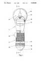
- FIG. 2is a longitudinal sectional view along the line 2--2 of FIG. 1.
- FIG. 3is a fragmental sectional view of the apparatus along line 3--3 of FIG. 2 illustrating attachment of the apparatus to an operating microscope.
- FIG. 4is a fragmental sectional view of an adjustment ring used in the apparatus showing an internal helical slot used in such ring.
- FIG. 5is a view of a steering mechanism with a reflecting mirror module used in the apparatus.
- FIG. 6is a view of a steering mechanism with a toroidal mirror module used in the apparatus.
- a modular apparatus for transforming and steering beams(hereinafter referred to as an "apparatus"), generally is designated by reference numeral 10. It consists of a telescopic unit 12, a casing 14, and a steering mechanism 16.
- Apparatus 10is connected to an operating microscope 18, e.g., by means of dovetail connection 19 (FIG. 3) and is fixed to the microscope by a screw 21.
- a surgeonuses a microscope for observing and manipulating laser beams B and directing them to the target area (not shown in the drawing).
- the apparatusis also connected to a laser source 20 which generates the abovementioned laser beams.
- the function of apparatus 10is to transform, focus and direct laser beams on the target area.
- laser source 20may be a System 451 C02 Surgical Laser manufactured by Coherent, Inc.
- Such a lasertypically may be used for the gynecological procedures, e.g., the destruction and removal of the neoplastic disease (tumors), cauterization and coagulation of smaller vascular channels, thereby preventing bleeding, etc.
- Telescopic unit 12has a tubular housing 22 which is rigidly attached to, or made integrally with casing 14.
- a cylindrical telescopic sleeve 24is slidingly fitted over the outer surface 26 of housing 22.
- the housinghas a longitudinal slot 28 (FIG. 2) in its outer surface 26.
- a first guide pin 30is attached to telescopic sleeve 24. Pin 30 extends inwardly from the sleeve into slot 28.
- a rear end 34 of sleeve 24, i.e., the end of the sleeve facing the laser beam source,has a bottom wall 36 with a central threaded opening 38. Opening 38 is intended for attachment to an appropriate connector of laser source 20.
- Sleeve 24is snugly fitted onto tubular housing 22, so that it can be moved into any axial position and held in this position due to friction between the parts. If necessary, however, a positive locking mechanism 39 can be provided on sleeve 24 for fixing it to housing 22 in any selected position.
- the locking mechanismmay have any conventional construction, such as a spring-loaded element with a friction pad. Since the construction of such mechanisms is well known in the art, it is not shown in the drawings.
- a first mirror holder 40is slidingly fitted inside sleeve 24.
- Holder 40has a cup-shaped configuration and holds concave mirror 42, which can be fixed within holder 40, e.g., by an adhesive.
- Concave mirror 42has a central opening 43 for passage of laser beam B, as will be described in more detail in connection with the operation of the apparatus.
- Attached to the outer surface of holder 40is a second guide pin 44.
- sleeve 24has a portion 46 of smaller diameter than the front part of the sleeve 24, so that a shoulder 48 is formed between both parts.
- An adjustment ring 50is slidingly fitted onto small diameter portion 46 and fixed against axial displacement by a stop ring 52.
- a low-friction ring 54is located between the front end of adjustment ring 50 and shoulder 48, and a similar low-friction ring 56 is located between the rear end of adjustment ring 50 and stop ring 52.
- adjustment ring 50can rotate on sleeve 24, but is restricted against axial displacement with respect to the sleeve.
- a helical groove 58(FIG. 4) is formed on the inner surface on the adjustment ring 50, and second guide pin 44 is inserted into groove 58. Since first mirror holder 40 is rigidly connected to pin 44, rotation of adjustment ring 50 will cause axial displacement of first mirror holder 40 with concave mirror 42 within sleeve 24. This is because pin 44 engages groove 58.
- adjustment ring 50has a knurled surface for convenience of grasping by hand and divisions 60 of scale 62 for adjustment with indicating mark 64 formed on outer surface 26 of sleeve 24 (FIG. 1).
- adjustment ring 50has a fixing ball 66.
- Ball 66is located in a longitudinal hole 68 of ring 50 and is constantly urged by spring 70 toward the surface of shoulder 48.
- Shoulder 48has circumferentially arranged indents (not shown). Spring-loaded ball 66 and the indents cooperate and lock adjustment ring 50, and thus concave mirror 42, in a required angular position in the manner known in the art.
- tubular housing 22supports a second mirror holder 74, which holds a convex mirror 76.
- Holder 74is rigidly attached to tubular housing 22 and is fixed, e.g., by an adhesive.
- the convex surface of mirror 76faces the concave surface of mirror 42.
- Both mirrors, i.e., 42 and 76,are located on the same optical path 78 which coincides with optical axis of incident laser beams B from beam source 20.
- Casing 14has a semi-cylindrical form (FIG. 1) and a viewing opening 80 to provide unobstructed view from microscope 18 (the optical system of which is not shown in the drawings).
- microscope 18the optical system of which is not shown in the drawings.
- the optical axis of microscope 18coincides with a longitudinal axis 82 of casing 14, which in turn is perpendicular to optical path 78 of the laser beam.
- the target point of the object being treated(which is not shown in the drawings) is also located on axis 82, but on the side opposite to the microscope.
- FIG. 2shows the apparatus in combination with beam-splitter module 84.
- Beam splitter 84is a mirror, which is transparent for a microscope viewer and, at the same time reflects both laser beams B, so that after reflection they coincide with the optical path 79 of microscope 18, i.e., they are directed to the target.
- Each moduleis removably attached to steering mechanism 16, e.g., by a screw 90 or any other quick releasable connector. It is understood that three modules are given as an example, and that any other number of modules can be employed.
- Steering mechanism 16comprises a slave-master mechanism of the type described in U.S. Pat. No. 4,526,477 to W. Taylor, 1985 and consists essentially of a manipulating handle 92 and a universal joint converting mechanism (not shown), which translates movements of handle 92 into appropriate movements of the module.
- a manipulating handle 92and a universal joint converting mechanism (not shown), which translates movements of handle 92 into appropriate movements of the module.
- Steering mechanism 16is attached to casing 14 by screws 98.
- casing 14has a rigidly attached circular handrest 94, for example by screws 96, only one of which is shown in FIG. 1.
- the entire apparatushad a length of 20 cm, a casing diameter of 7 cm, a handrest diameter of 10 cm, and a tubular housing diameter of 6 cm. Most of the parts are made of aluminum. Irrespective of the laser source, the apparatus allowed focusing/defocusing of the laser spot from 10 microns to 10 mm in diameter. type described in U.S. Pat. No. 4,526,447 to W. Taylor, 1985 and consists essentially of a manipulating handle 92 and a universal joint converting mechanism (not shown), which translates movements of handle 92 into appropriate movements of the module. In other words, by manipulating the handle it is possible to change the solid state angle of the module, and thus the position of the reflected laser beam on the object being treated.
- Steering mechanism 16is attached to casing 14 by screws 98.
- casing 14has a rigidly attached circular handrest 94, for example by screws 96, only one of which is shown in FIG. 1.
- the entire apparatushad a length of 20 cm, a casing diameter of 7 cm, a handrest diameter of 10 cm, and a tubular housing diameter of 6 cm. Most of the parts are made of aluminum. Irrespective of the laser source, the apparatus allowed focusing/defocusing of the laser spot from 10 microns to 10 mm in diameter.
- a surgeonPrior to operation a surgeon (or assistant) installs apparatus 10 on operating microscope 18 through dovetail 19 and locks the apparatus in the operating position by turning screw 21.
- the surgeonselects a modular unit required for the particular operation, e.g., beam splitter 84 (FIG. 2) would be selected for neurosurgical operation, then the modular unit is installed into the steering mechanism 16 and locked by screw 90.
- a modular unit required for the particular operatione.g., beam splitter 84 (FIG. 2) would be selected for neurosurgical operation, then the modular unit is installed into the steering mechanism 16 and locked by screw 90.
- adjustment ring 50is turned with respect to sleeve 24 by aligning the appropriate marks of scale 62 with indicating marks 64.
- guide pin 44engages helical groove 58, whereby first mirror holder 40 is shifted in the axial direction of laser beams B.
- a laser source 20is then connected to apparatus 10 through the articulating arm of fiber optic links (not shown in the drawings). Now the laser source is turned on for generating a guide or visible beam alone.
- a patientassumes an operating position on an operating table or chair.
- a visible beam B1 from laser source 20passes through opening 42 in concave mirror 42 and is guided along optical path 78 to convex mirror 76. Since this mirror has a convex surface, visible guide beam B1 is reflected from this mirror in a diverging form shown by projection lines B2 in FIG. 2.
- Beam B2falls onto the surface of concave mirror 42, which reflects the beam in a converging manner as designated by lines B3.
- This converging beamfalls onto the front surface of beam splitter 84, wherefrom it is reflected in the direction perpendicular to optical path 78 and is guided along optical path 79 of the microscope to the target area (not shown). Now the surgeon accurately aims the visible beam onto operating site, viewing the position of the beam through the microscope 18. Depending on the type of the operation to be performed, the surgeon focuses or defocuses the laser beam spot on the target area by grasping rubber jacket 32 and sliding sleeve 24 over tubular housing 22 until the required spot size (not shown) is achieved. In fact, this type of movement changes the distance between the convex and concave mirrors, thus changing solid state angles of the beams.
- the system of the present inventionguarantees that the power beam will coincide with the visible guide beam and that dimensions of spot sizes will be identical, the surgeon can now switch on the power laser beam with full confidence, and is ready to start the operation.
- the surgeonrests a wrist on handrest 94 in a comfortable position for stability and holds manipulating handle 92 of steering mechanism 16.
- the operationis performed through the above-mentioned masterslave mechanism, so that beam splitter 84 (or any other modular unit selected for the specific procedure) can describe any path required for positioning the beam in selected points on operation site. In fact, this action is similar to guiding the cursor on a computer monitor screen through a joystick.
- Toroidal mirror modular 86 and reflecting mirror module 88can be installed in the same manner as described above to perform surgical operations of different types.
- the apparatus of the inventionis simple in construction, easy to operate and inexpensive to manufacture. It is versatile in use, and can be utilized for various types of surgical procedures without replacement of its optical delivery systems. Also it has been shown that such modular apparatus substantially reduces energy losses, minimizes the spot-size diameter, broadens the range of focusing/defocusing capabilities, operates with all possible wavelength ranges of laser sources, and improves the surgeon's confidence in positioning the power and guide beams in the same target point.
- casing and sleeveare not necessarily be formed from aluminum alloy, but can be molded from the thermo-resistant plastic.
- the optical systemscan incorporate other mirrors or can be combined with optical elements.
- the shape and construction of casing 14 and handrest 94may be different from those shown in the drawings.
- Manipulating handle 92 and steering mechanism 16also may have different designs. For more accurate manipulation, handle 92 can be connected to a fine tuning thread mechanism. Modular units can be connected through quick-release snap-on mechanisms.
- the apparatusmay have dimensions different from the exampling ones given in the description.
- Steering mechanism 16can be driven by the servomotors under the control of a computer. It is also undrestood that means, other than a microscope, can be used for observing the beam spot on the target area.
- the steering mechanismcan be displaceable in the direction of its longitudinal axis and be slidingly installed in the casing.
Landscapes
- Physics & Mathematics (AREA)
- Optics & Photonics (AREA)
- Engineering & Computer Science (AREA)
- Plasma & Fusion (AREA)
- Mechanical Engineering (AREA)
- Laser Surgery Devices (AREA)
Abstract
Description
Claims (27)
Priority Applications (1)
| Application Number | Priority Date | Filing Date | Title |
|---|---|---|---|
| US07/576,790US5128509A (en) | 1990-09-04 | 1990-09-04 | Method and apparatus for transforming and steering laser beams |
Applications Claiming Priority (1)
| Application Number | Priority Date | Filing Date | Title |
|---|---|---|---|
| US07/576,790US5128509A (en) | 1990-09-04 | 1990-09-04 | Method and apparatus for transforming and steering laser beams |
Publications (1)
| Publication Number | Publication Date |
|---|---|
| US5128509Atrue US5128509A (en) | 1992-07-07 |
Family
ID=24306000
Family Applications (1)
| Application Number | Title | Priority Date | Filing Date |
|---|---|---|---|
| US07/576,790Expired - LifetimeUS5128509A (en) | 1990-09-04 | 1990-09-04 | Method and apparatus for transforming and steering laser beams |
Country Status (1)
| Country | Link |
|---|---|
| US (1) | US5128509A (en) |
Cited By (55)
| Publication number | Priority date | Publication date | Assignee | Title |
|---|---|---|---|---|
| US5382770A (en)* | 1993-01-14 | 1995-01-17 | Reliant Laser Corporation | Mirror-based laser-processing system with visual tracking and position control of a moving laser spot |
| US5546214A (en)* | 1995-09-13 | 1996-08-13 | Reliant Technologies, Inc. | Method and apparatus for treating a surface with a scanning laser beam having an improved intensity cross-section |
| US5688262A (en)* | 1994-01-14 | 1997-11-18 | Laser Industries Ltd. | Laser microscope adaptor apparatus with auto-focus |
| US5995265A (en)* | 1996-08-12 | 1999-11-30 | Black; Michael | Method and apparatus for treating a surface with a scanning laser beam having an improved intensity cross-section |
| US6071275A (en)* | 1995-01-05 | 2000-06-06 | Laser Industries, Ltd. | Laser microscope adaptor apparatus |
| US6373070B1 (en) | 1999-10-12 | 2002-04-16 | Fei Company | Method apparatus for a coaxial optical microscope with focused ion beam |
| US6520959B1 (en)* | 1998-03-31 | 2003-02-18 | Terumo Kabushiki Kaisha | Laser irradiation device and method for therapy of prostate gland by use thereof |
| US20030036680A1 (en)* | 2001-08-15 | 2003-02-20 | Michael Black | Method and apparatus for thermal ablation of biological tissue using a scanning laser beam with real-time video monitoring and monitoring of therapeutic treatment parameters |
| US20030102436A1 (en)* | 2000-03-20 | 2003-06-05 | Gerard Benas-Sayag | Column simultaneously focusing a particle beam and an optical beam |
| US6575964B1 (en) | 1998-02-03 | 2003-06-10 | Sciton, Inc. | Selective aperture for laser delivery system for providing incision, tissue ablation and coagulation |
| US20030109787A1 (en)* | 2001-12-12 | 2003-06-12 | Michael Black | Multiple laser diagnostics |
| US20030109860A1 (en)* | 2001-12-12 | 2003-06-12 | Michael Black | Multiple laser treatment |
| US6607523B1 (en) | 1999-03-19 | 2003-08-19 | Asah Medico A/S | Apparatus for tissue treatment |
| US6631153B2 (en)* | 2000-06-08 | 2003-10-07 | Cyber Laser Inc. | Light generating device and laser device using said light generating device |
| US20030216719A1 (en)* | 2001-12-12 | 2003-11-20 | Len Debenedictis | Method and apparatus for treating skin using patterns of optical energy |
| US20040082940A1 (en)* | 2002-10-22 | 2004-04-29 | Michael Black | Dermatological apparatus and method |
| US6743221B1 (en) | 2001-03-13 | 2004-06-01 | James L. Hobart | Laser system and method for treatment of biological tissues |
| US6770069B1 (en) | 2001-06-22 | 2004-08-03 | Sciton, Inc. | Laser applicator |
| US20060240381A1 (en)* | 1995-08-31 | 2006-10-26 | Biolase Technology, Inc. | Fluid conditioning system |
| US20070016176A1 (en)* | 2004-08-13 | 2007-01-18 | Dmitri Boutoussov | Laser handpiece architecture and methods |
| US20070208328A1 (en)* | 1995-08-31 | 2007-09-06 | Dmitri Boutoussov | Contra-angel rotating handpiece having tactile-feedback tip ferrule |
| US20070225779A1 (en)* | 2006-03-07 | 2007-09-27 | Reliant Technologies, Inc. | Treatment of vitiligo by micropore delivery of cells |
| US20070265606A1 (en)* | 2003-02-14 | 2007-11-15 | Reliant Technologies, Inc. | Method and Apparatus for Fractional Light-based Treatment of Obstructive Sleep Apnea |
| US20090069794A1 (en)* | 2007-09-10 | 2009-03-12 | Kurtz Ronald M | Apparatus, Systems And Techniques For Interfacing With An Eye In Laser Surgery |
| US20090067189A1 (en)* | 2005-06-07 | 2009-03-12 | Dmitri Boutoussov | Contra-angle rotating handpiece having tactile-feedback tip ferrule |
| US20090143775A1 (en)* | 1995-08-31 | 2009-06-04 | Rizoiu Ioana M | Medical laser having controlled-temperature and sterilized fluid output |
| US7655002B2 (en) | 1996-03-21 | 2010-02-02 | Second Sight Laser Technologies, Inc. | Lenticular refractive surgery of presbyopia, other refractive errors, and cataract retardation |
| US20100151406A1 (en)* | 2004-01-08 | 2010-06-17 | Dmitri Boutoussov | Fluid conditioning system |
| EP2278315A1 (en) | 2008-01-18 | 2011-01-26 | Lifescan Scotland Limited | Analyte test strip having predetermined calibration characteristics |
| USRE42594E1 (en) | 1998-10-16 | 2011-08-02 | Reliant Technologies, Inc. | Tissue cooling rod for laser surgery |
| US8203596B1 (en)* | 2007-12-20 | 2012-06-19 | Lockheed Martin Corporation | Panoramic imaging system with dual imagers |
| CN102614018A (en)* | 2012-04-10 | 2012-08-01 | 威海高科医疗设备有限公司 | Laser microsurgery sighting device |
| US8262646B2 (en) | 2006-01-20 | 2012-09-11 | Lensar, Inc. | System and method for providing the shaped structural weakening of the human lens with a laser |
| US8291913B2 (en) | 2004-06-14 | 2012-10-23 | Reliant Technologies, Inc. | Adaptive control of optical pulses for laser medicine |
| US8382745B2 (en) | 2009-07-24 | 2013-02-26 | Lensar, Inc. | Laser system and method for astigmatic corrections in association with cataract treatment |
| US8465478B2 (en) | 2009-07-24 | 2013-06-18 | Lensar, Inc. | System and method for performing LADAR assisted procedures on the lens of an eye |
| US8480659B2 (en) | 2008-07-25 | 2013-07-09 | Lensar, Inc. | Method and system for removal and replacement of lens material from the lens of an eye |
| US8500723B2 (en) | 2008-07-25 | 2013-08-06 | Lensar, Inc. | Liquid filled index matching device for ophthalmic laser procedures |
| US8556425B2 (en) | 2010-02-01 | 2013-10-15 | Lensar, Inc. | Purkinjie image-based alignment of suction ring in ophthalmic applications |
| USD694890S1 (en) | 2010-10-15 | 2013-12-03 | Lensar, Inc. | Laser system for treatment of the eye |
| USD695408S1 (en) | 2010-10-15 | 2013-12-10 | Lensar, Inc. | Laser system for treatment of the eye |
| US8617146B2 (en) | 2009-07-24 | 2013-12-31 | Lensar, Inc. | Laser system and method for correction of induced astigmatism |
| US8758332B2 (en) | 2009-07-24 | 2014-06-24 | Lensar, Inc. | Laser system and method for performing and sealing corneal incisions in the eye |
| US8801186B2 (en) | 2010-10-15 | 2014-08-12 | Lensar, Inc. | System and method of scan controlled illumination of structures within an eye |
| US8939967B2 (en) | 2011-08-03 | 2015-01-27 | Alcon Lensx, Inc. | Patient interface defogger |
| US9044304B2 (en) | 2011-12-23 | 2015-06-02 | Alcon Lensx, Inc. | Patient interface with variable applanation |
| US9180051B2 (en) | 2006-01-20 | 2015-11-10 | Lensar Inc. | System and apparatus for treating the lens of an eye |
| US9351792B2 (en) | 2003-03-27 | 2016-05-31 | The General Hospital Corporation | Method and apparatus for dermatological treatment and fractional skin resurfacing |
| US9375349B2 (en) | 2006-01-20 | 2016-06-28 | Lensar, Llc | System and method for providing laser shot patterns to the lens of an eye |
| US9393154B2 (en) | 2011-10-28 | 2016-07-19 | Raymond I Myers | Laser methods for creating an antioxidant sink in the crystalline lens for the maintenance of eye health and physiology and slowing presbyopia development |
| US9545338B2 (en) | 2006-01-20 | 2017-01-17 | Lensar, Llc. | System and method for improving the accommodative amplitude and increasing the refractive power of the human lens with a laser |
| US9889043B2 (en) | 2006-01-20 | 2018-02-13 | Lensar, Inc. | System and apparatus for delivering a laser beam to the lens of an eye |
| US10335315B2 (en) | 2013-02-01 | 2019-07-02 | Alcon Lensx, Inc. | Bi-radial patient interface |
| US10463541B2 (en) | 2011-03-25 | 2019-11-05 | Lensar, Inc. | System and method for correcting astigmatism using multiple paired arcuate laser generated corneal incisions |
| EP2798303B1 (en)* | 2011-12-28 | 2021-03-24 | Raytheon Company | System and method for providing thermal management of an obscured laser system |
Citations (8)
| Publication number | Priority date | Publication date | Assignee | Title |
|---|---|---|---|---|
| US4141362A (en)* | 1977-05-23 | 1979-02-27 | Richard Wolf Gmbh | Laser endoscope |
| US4228341A (en)* | 1978-12-12 | 1980-10-14 | Laser Industries Ltd. | Mechanical control system particularly useful for directing a laser beam |
| US4396285A (en)* | 1980-08-25 | 1983-08-02 | Coherent, Inc. | Laser system and its method of use |
| US4494540A (en)* | 1982-11-02 | 1985-01-22 | Erb Robert C | Universal microslad |
| US4520816A (en)* | 1983-01-12 | 1985-06-04 | Schachar Ronald A | Method and apparatus for delivering laser energy for ophthalmic use |
| US4526447A (en)* | 1983-05-07 | 1985-07-02 | Xanar, Inc. | Beam directing micromanipulator for laser device |
| US4597380A (en)* | 1982-09-30 | 1986-07-01 | Laser Industries Ltd. | Endoscopic attachment to a surgical laser |
| US4686992A (en)* | 1985-05-03 | 1987-08-18 | Coopervision, Inc. | Ophthalmic beam director |
- 1990
- 1990-09-04USUS07/576,790patent/US5128509A/ennot_activeExpired - Lifetime
Patent Citations (8)
| Publication number | Priority date | Publication date | Assignee | Title |
|---|---|---|---|---|
| US4141362A (en)* | 1977-05-23 | 1979-02-27 | Richard Wolf Gmbh | Laser endoscope |
| US4228341A (en)* | 1978-12-12 | 1980-10-14 | Laser Industries Ltd. | Mechanical control system particularly useful for directing a laser beam |
| US4396285A (en)* | 1980-08-25 | 1983-08-02 | Coherent, Inc. | Laser system and its method of use |
| US4597380A (en)* | 1982-09-30 | 1986-07-01 | Laser Industries Ltd. | Endoscopic attachment to a surgical laser |
| US4494540A (en)* | 1982-11-02 | 1985-01-22 | Erb Robert C | Universal microslad |
| US4520816A (en)* | 1983-01-12 | 1985-06-04 | Schachar Ronald A | Method and apparatus for delivering laser energy for ophthalmic use |
| US4526447A (en)* | 1983-05-07 | 1985-07-02 | Xanar, Inc. | Beam directing micromanipulator for laser device |
| US4686992A (en)* | 1985-05-03 | 1987-08-18 | Coopervision, Inc. | Ophthalmic beam director |
Cited By (71)
| Publication number | Priority date | Publication date | Assignee | Title |
|---|---|---|---|---|
| US5382770A (en)* | 1993-01-14 | 1995-01-17 | Reliant Laser Corporation | Mirror-based laser-processing system with visual tracking and position control of a moving laser spot |
| US5688262A (en)* | 1994-01-14 | 1997-11-18 | Laser Industries Ltd. | Laser microscope adaptor apparatus with auto-focus |
| US6071275A (en)* | 1995-01-05 | 2000-06-06 | Laser Industries, Ltd. | Laser microscope adaptor apparatus |
| US20090143775A1 (en)* | 1995-08-31 | 2009-06-04 | Rizoiu Ioana M | Medical laser having controlled-temperature and sterilized fluid output |
| US8033825B2 (en) | 1995-08-31 | 2011-10-11 | Biolase Technology, Inc. | Fluid and pulsed energy output system |
| US20090104580A1 (en)* | 1995-08-31 | 2009-04-23 | Rizoiu Ioana M | Fluid and pulsed energy output system |
| US20070208328A1 (en)* | 1995-08-31 | 2007-09-06 | Dmitri Boutoussov | Contra-angel rotating handpiece having tactile-feedback tip ferrule |
| US20110059417A9 (en)* | 1995-08-31 | 2011-03-10 | Rizoiu Ioana M | Fluid and pulsed energy output system |
| US20060240381A1 (en)* | 1995-08-31 | 2006-10-26 | Biolase Technology, Inc. | Fluid conditioning system |
| US5786924A (en)* | 1995-09-13 | 1998-07-28 | Reliant Technologies, Inc. | Method and apparatus for treating a surface with a scanning laser beam having an improved intensity cross-section |
| US5546214A (en)* | 1995-09-13 | 1996-08-13 | Reliant Technologies, Inc. | Method and apparatus for treating a surface with a scanning laser beam having an improved intensity cross-section |
| US7655002B2 (en) | 1996-03-21 | 2010-02-02 | Second Sight Laser Technologies, Inc. | Lenticular refractive surgery of presbyopia, other refractive errors, and cataract retardation |
| US5995265A (en)* | 1996-08-12 | 1999-11-30 | Black; Michael | Method and apparatus for treating a surface with a scanning laser beam having an improved intensity cross-section |
| US6575964B1 (en) | 1998-02-03 | 2003-06-10 | Sciton, Inc. | Selective aperture for laser delivery system for providing incision, tissue ablation and coagulation |
| US6520959B1 (en)* | 1998-03-31 | 2003-02-18 | Terumo Kabushiki Kaisha | Laser irradiation device and method for therapy of prostate gland by use thereof |
| USRE42594E1 (en) | 1998-10-16 | 2011-08-02 | Reliant Technologies, Inc. | Tissue cooling rod for laser surgery |
| USRE46208E1 (en) | 1998-10-16 | 2016-11-22 | Reliant Technologies, Llc | Method for cryogenically treating tissue below the skin surface |
| USRE43881E1 (en) | 1998-10-16 | 2012-12-25 | Reliant Technologies, Inc. | Tissue cooling rod for laser surgery |
| US6607523B1 (en) | 1999-03-19 | 2003-08-19 | Asah Medico A/S | Apparatus for tissue treatment |
| US6373070B1 (en) | 1999-10-12 | 2002-04-16 | Fei Company | Method apparatus for a coaxial optical microscope with focused ion beam |
| US20030102436A1 (en)* | 2000-03-20 | 2003-06-05 | Gerard Benas-Sayag | Column simultaneously focusing a particle beam and an optical beam |
| US20060097198A1 (en)* | 2000-03-20 | 2006-05-11 | Gerard Benas-Sayag | Column simultaneously focusing a particle beam and an optical beam |
| US7297948B2 (en) | 2000-03-20 | 2007-11-20 | Credence Systems Corporation | Column simultaneously focusing a particle beam and an optical beam |
| US6631153B2 (en)* | 2000-06-08 | 2003-10-07 | Cyber Laser Inc. | Light generating device and laser device using said light generating device |
| US7220256B2 (en) | 2001-03-13 | 2007-05-22 | Hobart James L | Laser system and method for treatment of biological tissues |
| US6743221B1 (en) | 2001-03-13 | 2004-06-01 | James L. Hobart | Laser system and method for treatment of biological tissues |
| US6770069B1 (en) | 2001-06-22 | 2004-08-03 | Sciton, Inc. | Laser applicator |
| US20030036680A1 (en)* | 2001-08-15 | 2003-02-20 | Michael Black | Method and apparatus for thermal ablation of biological tissue using a scanning laser beam with real-time video monitoring and monitoring of therapeutic treatment parameters |
| US20030109860A1 (en)* | 2001-12-12 | 2003-06-12 | Michael Black | Multiple laser treatment |
| US20030109787A1 (en)* | 2001-12-12 | 2003-06-12 | Michael Black | Multiple laser diagnostics |
| US20030216719A1 (en)* | 2001-12-12 | 2003-11-20 | Len Debenedictis | Method and apparatus for treating skin using patterns of optical energy |
| US20040082940A1 (en)* | 2002-10-22 | 2004-04-29 | Michael Black | Dermatological apparatus and method |
| US20070265606A1 (en)* | 2003-02-14 | 2007-11-15 | Reliant Technologies, Inc. | Method and Apparatus for Fractional Light-based Treatment of Obstructive Sleep Apnea |
| US9351792B2 (en) | 2003-03-27 | 2016-05-31 | The General Hospital Corporation | Method and apparatus for dermatological treatment and fractional skin resurfacing |
| US20100151406A1 (en)* | 2004-01-08 | 2010-06-17 | Dmitri Boutoussov | Fluid conditioning system |
| US8291913B2 (en) | 2004-06-14 | 2012-10-23 | Reliant Technologies, Inc. | Adaptive control of optical pulses for laser medicine |
| US20070016176A1 (en)* | 2004-08-13 | 2007-01-18 | Dmitri Boutoussov | Laser handpiece architecture and methods |
| US20090067189A1 (en)* | 2005-06-07 | 2009-03-12 | Dmitri Boutoussov | Contra-angle rotating handpiece having tactile-feedback tip ferrule |
| US10842675B2 (en) | 2006-01-20 | 2020-11-24 | Lensar, Inc. | System and method for treating the structure of the human lens with a laser |
| US9889043B2 (en) | 2006-01-20 | 2018-02-13 | Lensar, Inc. | System and apparatus for delivering a laser beam to the lens of an eye |
| US8262646B2 (en) | 2006-01-20 | 2012-09-11 | Lensar, Inc. | System and method for providing the shaped structural weakening of the human lens with a laser |
| US9180051B2 (en) | 2006-01-20 | 2015-11-10 | Lensar Inc. | System and apparatus for treating the lens of an eye |
| US9545338B2 (en) | 2006-01-20 | 2017-01-17 | Lensar, Llc. | System and method for improving the accommodative amplitude and increasing the refractive power of the human lens with a laser |
| US9375349B2 (en) | 2006-01-20 | 2016-06-28 | Lensar, Llc | System and method for providing laser shot patterns to the lens of an eye |
| US20070225779A1 (en)* | 2006-03-07 | 2007-09-27 | Reliant Technologies, Inc. | Treatment of vitiligo by micropore delivery of cells |
| US9504609B2 (en)* | 2007-09-10 | 2016-11-29 | Alcon Lensx, Inc. | Apparatus, systems and techniques for interfacing with an eye in laser surgery |
| US20090069794A1 (en)* | 2007-09-10 | 2009-03-12 | Kurtz Ronald M | Apparatus, Systems And Techniques For Interfacing With An Eye In Laser Surgery |
| US8203596B1 (en)* | 2007-12-20 | 2012-06-19 | Lockheed Martin Corporation | Panoramic imaging system with dual imagers |
| EP2278315A1 (en) | 2008-01-18 | 2011-01-26 | Lifescan Scotland Limited | Analyte test strip having predetermined calibration characteristics |
| EP2284528A1 (en) | 2008-01-18 | 2011-02-16 | Lifescan Scotland Limited | Method of manufacturing test strip lots having a predetermined calibration characteristic and system comprising such a test strip |
| US8500723B2 (en) | 2008-07-25 | 2013-08-06 | Lensar, Inc. | Liquid filled index matching device for ophthalmic laser procedures |
| US8480659B2 (en) | 2008-07-25 | 2013-07-09 | Lensar, Inc. | Method and system for removal and replacement of lens material from the lens of an eye |
| US8708491B2 (en) | 2008-07-25 | 2014-04-29 | Lensar, Inc. | Method and system for measuring an eye |
| US8382745B2 (en) | 2009-07-24 | 2013-02-26 | Lensar, Inc. | Laser system and method for astigmatic corrections in association with cataract treatment |
| US8758332B2 (en) | 2009-07-24 | 2014-06-24 | Lensar, Inc. | Laser system and method for performing and sealing corneal incisions in the eye |
| US8465478B2 (en) | 2009-07-24 | 2013-06-18 | Lensar, Inc. | System and method for performing LADAR assisted procedures on the lens of an eye |
| US8617146B2 (en) | 2009-07-24 | 2013-12-31 | Lensar, Inc. | Laser system and method for correction of induced astigmatism |
| US8485818B2 (en) | 2009-12-04 | 2013-07-16 | Biolase, Inc. | Fluid controller |
| US8556425B2 (en) | 2010-02-01 | 2013-10-15 | Lensar, Inc. | Purkinjie image-based alignment of suction ring in ophthalmic applications |
| US8801186B2 (en) | 2010-10-15 | 2014-08-12 | Lensar, Inc. | System and method of scan controlled illumination of structures within an eye |
| USD694890S1 (en) | 2010-10-15 | 2013-12-03 | Lensar, Inc. | Laser system for treatment of the eye |
| USD695408S1 (en) | 2010-10-15 | 2013-12-10 | Lensar, Inc. | Laser system for treatment of the eye |
| US10463541B2 (en) | 2011-03-25 | 2019-11-05 | Lensar, Inc. | System and method for correcting astigmatism using multiple paired arcuate laser generated corneal incisions |
| US8939967B2 (en) | 2011-08-03 | 2015-01-27 | Alcon Lensx, Inc. | Patient interface defogger |
| US9393154B2 (en) | 2011-10-28 | 2016-07-19 | Raymond I Myers | Laser methods for creating an antioxidant sink in the crystalline lens for the maintenance of eye health and physiology and slowing presbyopia development |
| US9937078B2 (en) | 2011-10-28 | 2018-04-10 | Raymond I Myers | Laser methods for creating an antioxidant sink in the crystalline lens for the maintenance of eye health and physiology and slowing presbyopia development |
| US9044304B2 (en) | 2011-12-23 | 2015-06-02 | Alcon Lensx, Inc. | Patient interface with variable applanation |
| EP2798303B1 (en)* | 2011-12-28 | 2021-03-24 | Raytheon Company | System and method for providing thermal management of an obscured laser system |
| CN102614018B (en)* | 2012-04-10 | 2015-02-04 | 威海高科医疗设备有限公司 | Laser microsurgery sighting device |
| CN102614018A (en)* | 2012-04-10 | 2012-08-01 | 威海高科医疗设备有限公司 | Laser microsurgery sighting device |
| US10335315B2 (en) | 2013-02-01 | 2019-07-02 | Alcon Lensx, Inc. | Bi-radial patient interface |
Similar Documents
| Publication | Publication Date | Title |
|---|---|---|
| US5128509A (en) | Method and apparatus for transforming and steering laser beams | |
| US5163936A (en) | Endoscopic mirror laser beam delivery system and method for controlling alignment | |
| US4473074A (en) | Microsurgical laser device | |
| US5198926A (en) | Optics for medical laser | |
| US7824089B2 (en) | Gradient index surgical illuminator | |
| US5095386A (en) | Optical system for generating lines of light using crossed cylindrical lenses | |
| FI82182B (en) | Device for connecting operating light to eye examination equipment | |
| US3703176A (en) | Slit lamp photocoagulator | |
| US6096028A (en) | Multi-slot laser surgery | |
| US5219347A (en) | Decoupled dual-beam control system | |
| WO2020123842A1 (en) | Ophthalmic surgery laser system and method for utilizing same for ophthalmic surgery | |
| EP1653896A2 (en) | Coaxial illuminated laser endoscopic probe and active numerical aperture control | |
| CN109363625B (en) | An Augmented Reality System for Online Marking of Astigmatism Axial Position | |
| US4801198A (en) | Slit lamp attachment | |
| US4520824A (en) | Instrument for ophthalmic laser surgery | |
| US4228341A (en) | Mechanical control system particularly useful for directing a laser beam | |
| WO1993011454A1 (en) | Binocular bent-axis loupes | |
| JPH0348807B2 (en) | ||
| Shapshay et al. | New microspot micromanipulator for CO2 laser application in otolaryngology—Head and neck surgery | |
| Bellnier et al. | Design and construction of a light‐delivery system for photodynamic therapy | |
| US5257992A (en) | Micromanipulator apparatus for surgical laser | |
| WO2022208551A1 (en) | A device and method for positioning the binocular head of a surgical microscope | |
| RU2043067C1 (en) | On-forehead illuminator | |
| JPS59118130A (en) | Microscope for ophthalmic operation | |
| JPH02226217A (en) | Astronomical telescope |
Legal Events
| Date | Code | Title | Description |
|---|---|---|---|
| AS | Assignment | Owner name:RELIANT LASER CORPORATION Free format text:ASSIGNMENT OF ASSIGNORS INTEREST.;ASSIGNORS:BLACK, MICHAEL;KUPERSHMIDT, VLADIMIR;REEL/FRAME:005428/0380 Effective date:19900830 | |
| STCF | Information on status: patent grant | Free format text:PATENTED CASE | |
| FPAY | Fee payment | Year of fee payment:4 | |
| SULP | Surcharge for late payment | ||
| REMI | Maintenance fee reminder mailed | ||
| FP | Lapsed due to failure to pay maintenance fee | Effective date:20000707 | |
| FEPP | Fee payment procedure | Free format text:PETITION RELATED TO MAINTENANCE FEES FILED (ORIGINAL EVENT CODE: PMFP); ENTITY STATUS OF PATENT OWNER: SMALL ENTITY | |
| FEPP | Fee payment procedure | Free format text:PETITION RELATED TO MAINTENANCE FEES GRANTED (ORIGINAL EVENT CODE: PMFG); ENTITY STATUS OF PATENT OWNER: SMALL ENTITY | |
| FEPP | Fee payment procedure | Free format text:PAYOR NUMBER ASSIGNED (ORIGINAL EVENT CODE: ASPN); ENTITY STATUS OF PATENT OWNER: SMALL ENTITY | |
| FPAY | Fee payment | Year of fee payment:8 | |
| SULP | Surcharge for late payment | ||
| AS | Assignment | Owner name:RELIANT TECHNOLOGIES, INC., CALIFORNIA Free format text:MERGER;ASSIGNOR:RELIANT LASER CORPORATION;REEL/FRAME:012483/0501 Effective date:20011119 | |
| PRDP | Patent reinstated due to the acceptance of a late maintenance fee | Effective date:20020128 | |
| REFU | Refund | Free format text:REFUND - SURCHARGE, PETITION TO ACCEPT PYMT AFTER EXP, UNINTENTIONAL (ORIGINAL EVENT CODE: R2551); ENTITY STATUS OF PATENT OWNER: SMALL ENTITY Free format text:REFUND - SURCHARGE FOR LATE PAYMENT, SMALL ENTITY (ORIGINAL EVENT CODE: R2554); ENTITY STATUS OF PATENT OWNER: SMALL ENTITY | |
| FPAY | Fee payment | Year of fee payment:12 | |
| REMI | Maintenance fee reminder mailed | ||
| SULP | Surcharge for late payment | Year of fee payment:11 |