US5127910A - Combined syringe and needle shield and method of manufacture - Google Patents
Combined syringe and needle shield and method of manufactureDownload PDFInfo
- Publication number
- US5127910A US5127910AUS07/676,048US67604891AUS5127910AUS 5127910 AUS5127910 AUS 5127910AUS 67604891 AUS67604891 AUS 67604891AUS 5127910 AUS5127910 AUS 5127910A
- Authority
- US
- United States
- Prior art keywords
- shield
- needle
- diameter
- distal
- collar means
- Prior art date
- Legal status (The legal status is an assumption and is not a legal conclusion. Google has not performed a legal analysis and makes no representation as to the accuracy of the status listed.)
- Expired - Lifetime
Links
- 238000000034methodMethods0.000titledescription11
- 238000004519manufacturing processMethods0.000titledescription3
- 238000010276constructionMethods0.000description12
- 230000001681protective effectEffects0.000description8
- 230000008569processEffects0.000description5
- 206010069803Injury associated with deviceDiseases0.000description4
- 238000000465mouldingMethods0.000description4
- 239000004033plasticSubstances0.000description4
- 239000000463materialSubstances0.000description3
- 230000000295complement effectEffects0.000description2
- 210000005069earsAnatomy0.000description2
- 208000015181infectious diseaseDiseases0.000description2
- 238000002347injectionMethods0.000description2
- 239000007924injectionSubstances0.000description2
- 230000002093peripheral effectEffects0.000description2
- 208000030507AIDSDiseases0.000description1
- 208000035473Communicable diseaseDiseases0.000description1
- 239000004743PolypropyleneSubstances0.000description1
- 239000000853adhesiveSubstances0.000description1
- 230000001070adhesive effectEffects0.000description1
- 239000008280bloodSubstances0.000description1
- 210000004369bloodAnatomy0.000description1
- 230000000994depressogenic effectEffects0.000description1
- 239000003814drugSubstances0.000description1
- 229940079593drugDrugs0.000description1
- 238000009434installationMethods0.000description1
- 230000002427irreversible effectEffects0.000description1
- 230000007246mechanismEffects0.000description1
- 230000004048modificationEffects0.000description1
- 238000012986modificationMethods0.000description1
- 229920005668polycarbonate resinPolymers0.000description1
- 239000004431polycarbonate resinSubstances0.000description1
- -1polypropylenePolymers0.000description1
- 229920001155polypropylenePolymers0.000description1
- 230000004044responseEffects0.000description1
- 230000000717retained effectEffects0.000description1
- 230000007480spreadingEffects0.000description1
- 238000003892spreadingMethods0.000description1
- 238000003466weldingMethods0.000description1
Images


Classifications
- A—HUMAN NECESSITIES
- A61—MEDICAL OR VETERINARY SCIENCE; HYGIENE
- A61M—DEVICES FOR INTRODUCING MEDIA INTO, OR ONTO, THE BODY; DEVICES FOR TRANSDUCING BODY MEDIA OR FOR TAKING MEDIA FROM THE BODY; DEVICES FOR PRODUCING OR ENDING SLEEP OR STUPOR
- A61M5/00—Devices for bringing media into the body in a subcutaneous, intra-vascular or intramuscular way; Accessories therefor, e.g. filling or cleaning devices, arm-rests
- A61M5/178—Syringes
- A61M5/31—Details
- A61M5/32—Needles; Details of needles pertaining to their connection with syringe or hub; Accessories for bringing the needle into, or holding the needle on, the body; Devices for protection of needles
- A61M5/3205—Apparatus for removing or disposing of used needles or syringes, e.g. containers; Means for protection against accidental injuries from used needles
- A61M5/321—Means for protection against accidental injuries by used needles
- A61M5/3243—Means for protection against accidental injuries by used needles being axially-extensible, e.g. protective sleeves coaxially slidable on the syringe barrel
- A61M5/3271—Means for protection against accidental injuries by used needles being axially-extensible, e.g. protective sleeves coaxially slidable on the syringe barrel with guiding tracks for controlled sliding of needle protective sleeve from needle exposing to needle covering position
- A—HUMAN NECESSITIES
- A61—MEDICAL OR VETERINARY SCIENCE; HYGIENE
- A61M—DEVICES FOR INTRODUCING MEDIA INTO, OR ONTO, THE BODY; DEVICES FOR TRANSDUCING BODY MEDIA OR FOR TAKING MEDIA FROM THE BODY; DEVICES FOR PRODUCING OR ENDING SLEEP OR STUPOR
- A61M5/00—Devices for bringing media into the body in a subcutaneous, intra-vascular or intramuscular way; Accessories therefor, e.g. filling or cleaning devices, arm-rests
- A61M5/178—Syringes
- A61M5/31—Details
- A61M2005/3103—Leak prevention means for distal end of syringes, i.e. syringe end for mounting a needle
- A61M2005/3104—Caps for syringes without needle
- A—HUMAN NECESSITIES
- A61—MEDICAL OR VETERINARY SCIENCE; HYGIENE
- A61M—DEVICES FOR INTRODUCING MEDIA INTO, OR ONTO, THE BODY; DEVICES FOR TRANSDUCING BODY MEDIA OR FOR TAKING MEDIA FROM THE BODY; DEVICES FOR PRODUCING OR ENDING SLEEP OR STUPOR
- A61M5/00—Devices for bringing media into the body in a subcutaneous, intra-vascular or intramuscular way; Accessories therefor, e.g. filling or cleaning devices, arm-rests
- A61M5/178—Syringes
- A61M5/31—Details
- A61M5/32—Needles; Details of needles pertaining to their connection with syringe or hub; Accessories for bringing the needle into, or holding the needle on, the body; Devices for protection of needles
- A61M5/3202—Devices for protection of the needle before use, e.g. caps
- A—HUMAN NECESSITIES
- A61—MEDICAL OR VETERINARY SCIENCE; HYGIENE
- A61M—DEVICES FOR INTRODUCING MEDIA INTO, OR ONTO, THE BODY; DEVICES FOR TRANSDUCING BODY MEDIA OR FOR TAKING MEDIA FROM THE BODY; DEVICES FOR PRODUCING OR ENDING SLEEP OR STUPOR
- A61M5/00—Devices for bringing media into the body in a subcutaneous, intra-vascular or intramuscular way; Accessories therefor, e.g. filling or cleaning devices, arm-rests
- A61M5/178—Syringes
- A61M5/31—Details
- A61M5/32—Needles; Details of needles pertaining to their connection with syringe or hub; Accessories for bringing the needle into, or holding the needle on, the body; Devices for protection of needles
- A61M5/3205—Apparatus for removing or disposing of used needles or syringes, e.g. containers; Means for protection against accidental injuries from used needles
- A61M5/321—Means for protection against accidental injuries by used needles
- A61M5/3243—Means for protection against accidental injuries by used needles being axially-extensible, e.g. protective sleeves coaxially slidable on the syringe barrel
- A61M5/3271—Means for protection against accidental injuries by used needles being axially-extensible, e.g. protective sleeves coaxially slidable on the syringe barrel with guiding tracks for controlled sliding of needle protective sleeve from needle exposing to needle covering position
- A61M5/3272—Means for protection against accidental injuries by used needles being axially-extensible, e.g. protective sleeves coaxially slidable on the syringe barrel with guiding tracks for controlled sliding of needle protective sleeve from needle exposing to needle covering position having projections following labyrinth paths
Definitions
- This inventionrelates to syringes and, in particular, to a hypodermic syringe having a retractable needle guard primarily for the purpose of preventing accidental needle sticks.
- One approach to this problemis to provide a retractable shield which, after the syringe has been used, can be pulled to an extended position where it covers the needle, making it difficult for an individual to accidentally contact the needle.
- a common feature of such constructionsis that when the shield is pulled to its extended position, it is locked so that it cannot be retracted (thus exposing the needle) except by application of extraordinary force.
- constructionshave been proposed which include an opening or slot in the side of the shield. This is undesirable because the needle can extend through the opening if the shield is deflected in the extended position.
- Another object of the inventionis to provide a relatively inexpensive protective shield which satisfies the functional requirements of a needle shield and includes none of the drawbacks mentioned above.
- Another objectis to provide an extendable needle shield for a syringe which performs all of the necessary functions of such a shield and which is particularly well suited to an automated process of manufacture.
- a further object of the inventionis to provide an extendable needle shield for a standard syringe which is improved both from the points of view of functional utility and cost of manufacture.
- a still further objectis to provide an inexpensive method of assembling a protective shield and syringe.
- a needle shieldis mounted coaxially on a syringe barrel.
- the shieldincludes one or more elongated keys on its inner surface.
- a collaris provided on the forward end of the barrel.
- the collarmay be a separate part or it may be integrally formed with the barrel and includes on its outer surface at least one locking slot. The key slides in a path outside of the locking slot and can be rotated into the locking slot when the shield is extended.
- Both the collar and shieldcan be molded from plastic materials so that the cost of the shield is relatively low.
- the shieldincludes a plurality of elongated locking keys and the collar includes a plurality of locking slots.
- Each locking slotis defined by opposing walls, at least one of which includes a ramp over which the keys can ride when the shield is pulled to its extended position and rotated.
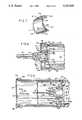
- FIG. 1is a side elevational view, partly in section, showing a needle shield and collar in accordance with a preferred embodiment of the invention secured to a conventional syringe with the shield in its retracted position;
- FIG. 2is an enlarged sectional view with the shield in cross-section in its extended position
- FIG. 3is a further enlarged partial side sectional view showing details of the collar and shield
- FIG. 4is a sectional view along the line 4--4 of FIG. 2 with the shield pulled to its extended position but before rotation;
- FIG. 5is a sectional view along the line 4--4 of FIG. 2 showing the shield rotated into its locked position
- FIG. 6 and 7are perspective views of a preferred embodiment of the collar
- FIG. 8is a side sectional view showing a collar construction for use with a large diameter barrel.
- FIG. 9is an enlarged side sectional view showing a shield in its extended position relative to the collar of FIG. 8.
- the inventionis intended to be used in conjunction with a conventional syringe; however, a protective shield in accordance with the invention can be used for any medical or laboratory device having a needle, such as a blood collection tube holder with a double ended needle.
- a protective shield in accordance with the inventioncan be used for any medical or laboratory device having a needle, such as a blood collection tube holder with a double ended needle.
- the term "syringe"is intended to include any medical or scientific device including a needle wherein it is desired to protect a user from accidental needle sticks.
- distal end of a partrefers to the end of the part closest to the needle point.
- proximal end of a partrefers to the end furthest from the needle point.
- FIGS. 1-6show a conventional syringe comprising a tubular barrel 10 having a finger flange 11, a plunger 12 slidable within the barrel 10, and a needle assembly through which the contents of the barrel are dispensed when the plunger 12 is depressed.
- the barrel 10may be tapered very slightly (not shown) from a larger diameter proximal end to a smaller diameter distal end for molding purposes.
- the needle assemblycomprises a needle 14 and a hub 16 at the proximal end of the needle.
- a conically shaped luer tip 17 and luer lock skirt 18are integrally formed at the distal end of barrel 10 with luer lock skirt 18 encircling luer tip 17. As shown in FIG.
- the interior surface of the luer lock skirt 18includes an internal thread 18A adapted to threadably engage complementary locking ears 16A on the needle hub 16.
- the exterior surface of luer lock skirt 18includes a multiplicity of ribs 19 parallel to the central axis of the barrel.
- the needle and luer arrangement of FIG. 8is the same as that of FIGS. 1-6.
- a needle sheath 20covers needle 14 as a protective device. Sheath 20 frictionally engages hub 16 and can be used to disconnect the needle assembly from the luer lock skirt 18 in conventional fashion.
- the collar employed in accordance with the preferred embodiment of the inventionis shown generally at 22 (FIGS. 2, 6 and 8).
- collar 22may be integrally formed as a part of the barrel 10. It includes six equally spaced and integrally formed identical triangular protrusions 24, with the apex of each protrusion extending away from the needle. Keyways 25 are formed between each adjacent pair of protrusions 24.
- the triangular protrusions 24each include angled surfaces 24A and 24B, side surfaces 25C, a slot 26 and a surface 27 which is generally circumferential and functions as a stop as explained below.
- the slot 26includes a sloped distal surface 26A. It is not necessary that protrusions 24 be triangular in shape and other configurations can be used to provide a stop 27 for the keys and the angled surfaces 25A and 25B necessary to guide the keys into the keyways during the assembly process as described below.
- the slot 26is formed in protrusion 24 and extends proximally to the point of the protrusion 24 to expose the detenting surface 26A and facilitate the entry of the detent 50 into the slot 26 during assembly, and also to facilitate efficient molding of the collar.
- a rectangular locking slot 31is formed between each pair of walls 28 and 30, which are ramp shaped in cross section as shown most clearly in FIGS. 4, 5 and 6.
- the surface of locking slot 31is slightly elevated relative to the level of the keyways 25, i.e., the collar diameter at the locking slots 31 is slightly greater than the collar diameter at the keyways.
- the slight increase in the collar diameter at the locking slotsremoves some of the slack between the needle shield (described below) and the collar 22 resulting from the slight taper of the barrel 10 in the preferred embodiment. This prevents or at least minimizes wobble or play of the shield when it is locked in the extended position.
- a circular detent 32is positioned between each pair of triangular protrusions 24 with the forward points of detents 32 lying just in front of the bases of triangular projections 24.
- the rear end of collar 22includes a peripheral rigid tooth 34 adapted to engage the ribs 19 in the luer lock skirt 18 to retain the collar 22 on the syringe.
- Collar 22is molded of a rigid plastic material such as polycarbonate resin so that when the collar is pushed over the luer lock skirt 18, the angled surface of the rigid tooth 34 allows the tooth to move over the ribs 19 until the proximal end of the collar is seated toward the distal end of the barrel with the rigid tooth 34 deforming the ribs 19 of the luer lock skirt 18 to permanently retain the collar in place on the syringe barrel 10.
- a circumferential groovemay be formed in collar 22 to receive the peripheral tooth 34.
- Locking lip 34will bite sufficiently into the outer surface of the luer skirt 18 to prevent axial movement of collar 22 but in some cases slight rotation or rocking of the collar may occur.
- the tooth 34may be formed with gaps (not shown) so that not all of the ribs 19 on the outside of the luer lock skirt 18 will be deformed. The non-deformed ribs 19 falling into the gaps resist rotation or rocking of the collar 22 relative to barrel 10.
- the inner surface of collar 22may be provided with lugs 35 molded on the inside of the collar and adapted to fit between the ribs 19 on the outside of the luer lock skirt 18 to prevent positively any rotational movement with the meshed ribs 19.
- the needle shieldcomprises an elongated plastic cylinder 40 (e.g., made of polypropylene) having three keys 42 integrally formed on its interior surface.
- An end rim 44is formed at the proximal end of shield 40. As shown in FIG. 2, end rim 44 is adapted to abut against the proximal end of collar 22 to limit the forward movement of the shield.
- Each of the keys 42includes a distal triangular point 46 and extends from the distal end of the shield to a point just short of the distal point of the triangular protrusions 24 on collar 22 when the shield is in its extended position as shown in FIG. 2.
- End rim 44includes three cutout sections 45 which align with each of the keys 42.
- Cutout sections 45facilitate the process for molding keys 42 but serve no functional purpose after the device has been assembled.
- the keys 42terminate in flat surfaces 48.
- the shield 40With the three keys 42 in the keyways 25 in the retracted position (FIG. 1), rotational movement of the shield 40 is prevented by abutment of the edges of keys 42 against the side surfaces 24C of protrusions 24; therefore, torque can be applied to the needle while holding shield 40 to thread (or unthread) needles onto (or from) the syringe. This cannot be done with constructions in which a shield rotates freely with respect to the syringe.
- detents 50are also formed on the inner surface of the shield 40 toward its forward end.
- the detents 50may be equally spaced and are adapted to be received within the slots 26 in the triangular protrusions 24 to retain the shield 40 in its retracted position (FIG. 1).
- the detents 50are each spaced thirty degrees from an adjacent key 42. It is not necessary that the detents be equally spaced.
- Each of the detentsincludes a sloped distal surface 50A and a proximal surface 50B more gradually sloped than slope 50A.
- Cap 52is placed on the forward end of the shield 40.
- Cap 52is molded from a resilient plastic material (such as polyallomer) and includes a side wall 53 and an end wall 54 which is adapted to be positioned between the distal end of collar 22 and the proximal end of the needle sheath 20 (FIG. 1) for substantially closing the distal end of shield 40.
- Side wall 53is shaped as shown so that end cap 52 can be retained on shield 40 by the interlocking mechanical engagement of the side wall 53 and a complementary projection 55 at the forward end of shield 40.
- Cap 52need not be a separate part and can, instead, be formed as an integral part of shield 40.
- the end wall 54includes a central needle aperture which is made small enough that the end of shield 40 is closed to the maximum extent while allowing the locking ears 16A of needle hub 16 to be extended through the aperture to permit needles to be mounted and removed while the shield 40 is in its retracted position (FIG. 8).
- the apertureis not, however, large enough to allow the proximal end of the sheath to pass through it.
- the minimum needle aperturereduces the likelihood that a child or person with small fingers may accidentally contact the needle point.
- End cap 52also makes the distal end of shield 40 more rigid and resistive to deformation when dropped or otherwise impacted upon a hard surface.
- the rim 54 and its position between the proximal end of needle sheath 20 and the distal end of barrel 10serves a functional purpose when removing or installing needles on the luer tip 17 (FIG. 8), for example, when the filling and injection needles are different.
- the syringeis held by shield 40 with the shield in its retracted position.
- Needle hub 16, projecting from the proximal end of the protective sheath 20,is inserted through the aperture in the end wall 54 and the hub telescoped onto the luer tip 17.
- the needle hub 16is rotated by twisting and pushing with the sheath to thread the locking tabs 16A within the internal threads 18A in the luer skirt 18 until needle 14 is mounted on the syringe.
- the needlesmove axially relative to sheath 20.
- the shield 40is prevented from rotating by abutment of keys 42 against surfaces 24C of protrusions 26, while the rim 54 provides a surface against which the needle sheath can be forced.
- the end wall 54is particularly important when the invention is used in conjunction with large diameter barrels.
- FIGS. 8 and 9wherein like numerals are used to identify parts identical to those shown in the embodiment of FIGS. 1-6.
- the needle 14 and hub 16are the same as in FIG. 1 as is the luer tip 17 and the luer lock skirt 18.
- the collar 122includes two concentric hubs or sleeves 124 and 126 supported by an annular strut 128 preferably forming an I-beam in cross-section as shown in FIG. 9.
- the cross-sectional shapeis not critical, however, and those skilled in the art will readily understand that the cross-section could be cup- or channel-shaped, with a web extending either distally or proximally between the concentric hubs or sleeves.
- the end cap 152includes side wall 153 and end wall 154 which, as shown, covers a substantial portion of the barrel opening and thus greatly reduces the risk of accidental needle stick when the shield is in its extended position.
- the devicemay be assembled as follows. Shield 40 is inserted on the forward end of the barrel 10 of an assembled syringe to its retracted position shown in FIG. 1 (prior to installation of the needle 14 and sheath 20 on the syringe). With the shield 40 held in position, the collar 22 is then placed over the luer lock skirt 18 inside of the shield 40. Engagement of the triangular protrusions 24 on collar 22 with the triangular points 46 at the end of keys 42 on shield 40, as the collar 22 is pushed onto the luer lock skirt 18, causes the shield 40 to rotate until the keys 42 are positioned in the keyways over detents 32 between adjacent triangular protrusions 24.
- the collar 22is pushed inwardly until the proximal end of the collar butts up against the face 56 on the syringe barrel 10. In this position, as shown in FIG. 3, the three detents 50 are seated in the slots 26 of three of the protrusions 24. After the shield 40 and collar 22 have been assembled on the syringe, end cap 52 is placed on the shield 40. The needle 14 with its sheath 20 may then be attached to the luer tip to complete the assembly.
- collar 22may be positioned within shield 40 with the keys 42 positioned in the appropriate keyways 25.
- the shield and collarmay then be telescoped together over the syringe barrel with the collar being forced onto the luer lock skirt as the shield is moved to the retracted position in which the proximal end of the collar abuts against the distal face of the syringe barrel.
- This proceduremay be used with the end cap 52 in place on the shield which means that this assembly process could be used with a shield having end wall 54 integrally formed as a portion of the shield as mentioned above.
- this alternative assembly methodcan be used with an open shield in which case end cap 52 can be placed on the shield after assembly.
- the use of the syringemay be conventional. Needle sheath 20 is removed and medication drawn into barrel 10 by withdrawal of plunger 12 with the shield in its retracted position shown in FIG. 1. After the contents of the syringe have been injected into a patient, the shield 40 is pulled forward into the extended position shown in FIG. 2. When this happens, the keys 42 slide in the keyways 25 over detents 32 between the adjacent protrusions 24 on collar 22 (FIG. 4) and the distal surfaces 50A of detents 50 slide over surfaces 26A (FIG. 2) of slots 26. The user can feel the rear edges 48 of keys 42 clearing detents 32, which signals that the shield 40 is fully extended.
- the userrotates shield 40 causing the keys 42 to move over the adjacent ramps 28 (or 30) until the keys fall into the locking slots 31 formed between each pair of ramps 28 and 30 (see FIG. 5). Because of the arrangement of the ramps 28 and 30, the shield can be locked by rotating it either clockwise or counterclockwise.
- the rear edge 48 of each keyabuts against the squared off surface 27 of one of the triangular protrusions 24 so that the shield cannot be returned to its retracted position without application of excessive force. Because of the interlocking relationship of the square key and locking slots, shield 40 can no longer be rotated and, accordingly, the shield is permanently locked in place.
Landscapes
- Health & Medical Sciences (AREA)
- Engineering & Computer Science (AREA)
- Heart & Thoracic Surgery (AREA)
- Vascular Medicine (AREA)
- Anesthesiology (AREA)
- Biomedical Technology (AREA)
- Environmental & Geological Engineering (AREA)
- Hematology (AREA)
- Life Sciences & Earth Sciences (AREA)
- Animal Behavior & Ethology (AREA)
- General Health & Medical Sciences (AREA)
- Public Health (AREA)
- Veterinary Medicine (AREA)
- Infusion, Injection, And Reservoir Apparatuses (AREA)
Abstract
Description
Claims (10)
Priority Applications (1)
| Application Number | Priority Date | Filing Date | Title |
|---|---|---|---|
| US07/676,048US5127910A (en) | 1988-06-28 | 1991-03-27 | Combined syringe and needle shield and method of manufacture |
Applications Claiming Priority (2)
| Application Number | Priority Date | Filing Date | Title |
|---|---|---|---|
| US07/212,528US5053018A (en) | 1988-06-28 | 1988-06-28 | Combined syringe and needle shield and method of manufacture |
| US07/676,048US5127910A (en) | 1988-06-28 | 1991-03-27 | Combined syringe and needle shield and method of manufacture |
Related Parent Applications (1)
| Application Number | Title | Priority Date | Filing Date |
|---|---|---|---|
| US07/212,528ContinuationUS5053018A (en) | 1988-06-28 | 1988-06-28 | Combined syringe and needle shield and method of manufacture |
Publications (1)
| Publication Number | Publication Date |
|---|---|
| US5127910Atrue US5127910A (en) | 1992-07-07 |
Family
ID=26907232
Family Applications (1)
| Application Number | Title | Priority Date | Filing Date |
|---|---|---|---|
| US07/676,048Expired - LifetimeUS5127910A (en) | 1988-06-28 | 1991-03-27 | Combined syringe and needle shield and method of manufacture |
Country Status (1)
| Country | Link |
|---|---|
| US (1) | US5127910A (en) |
Cited By (35)
| Publication number | Priority date | Publication date | Assignee | Title |
|---|---|---|---|---|
| US5312370A (en)* | 1988-06-28 | 1994-05-17 | Sherwood Medical Company | Combined syringe and needle shield |
| US5314414A (en)* | 1989-03-02 | 1994-05-24 | Needlepoint Guard, Inc. | Hypodermic needle guard and method to prevent needle stick injuries |
| US5338311A (en) | 1993-08-23 | 1994-08-16 | Mahurkar Sakharam D | Hypodermic needle assembly |
| US5651774A (en)* | 1996-09-11 | 1997-07-29 | William J. Taranto | Hypodermic syringe with safety shield and method of using same |
| US5658254A (en)* | 1995-03-31 | 1997-08-19 | Becton, Dickinson And Company | Syringe having safety needle shield |
| US5836921A (en) | 1993-08-23 | 1998-11-17 | Mahurkar; Sakharam D. | Hypodermic needle assembly |
| US5843041A (en)* | 1989-03-02 | 1998-12-01 | Hake; Lawrence W. | Hypodermic needle guard and method to prevent needle stick injuries |
| US6017329A (en)* | 1989-03-02 | 2000-01-25 | Hake; Lawrence W. | Hypodermic needle guard and method to prevent needle stick injuries |
| US6117112A (en) | 1997-11-18 | 2000-09-12 | Mahurkar; Sakharam D. | Single-use safety syringe |
| US6280401B1 (en) | 1993-08-23 | 2001-08-28 | Sakharam D. Mahurkar | Hypodermic needle assembly |
| US6527742B1 (en) | 2001-11-14 | 2003-03-04 | Robert C. Malenchek | Safety syringe |
| US20040230158A1 (en)* | 2003-05-13 | 2004-11-18 | Robert Malenchek | Adaptor for converting a non-safety syringe into a safety syringe |
| US7118552B2 (en) | 2000-02-18 | 2006-10-10 | Astrazeneca Ab | Automatically operable safety shield system for syringes |
| US20080215001A1 (en)* | 2005-09-01 | 2008-09-04 | Owen Mumford Limited | Needle Shroud Assembly |
| US7481797B2 (en) | 2001-11-28 | 2009-01-27 | Mahurkar Sakharam D | Retractable needle single use safety syringe |
| US20090105663A1 (en)* | 2007-10-11 | 2009-04-23 | Rexam Pharma La Verpilliere | Safety device for a liquid injection syringe, and a syringe assembly including the device |
| US7918821B2 (en) | 2009-05-05 | 2011-04-05 | Mahurkar Sakharam D | Universal safety syringe |
| US7985216B2 (en) | 2004-03-16 | 2011-07-26 | Dali Medical Devices Ltd. | Medicinal container engagement and automatic needle device |
| US8323251B2 (en) | 2008-01-14 | 2012-12-04 | Fenwal, Inc. | Phlebotomy needle assembly and frangible cover |
| US8376998B2 (en) | 2003-09-17 | 2013-02-19 | Elcam Medical Agricultural Cooperative Association Ltd. | Automatic injection device |
| US20140228772A1 (en)* | 2011-09-23 | 2014-08-14 | Sanofi-Aventis Deutschland Gmbh | Needle safety device |
| US20170112998A1 (en)* | 2007-10-02 | 2017-04-27 | Medimop Medical Projects Ltd. | Method of using a key to secure components of a drug delivery system during assembly |
| US10758679B2 (en) | 2015-05-29 | 2020-09-01 | West Pharma. Services IL, Ltd. | Linear rotation stabilizer for a telescoping syringe stopper driverdriving assembly |
| US10912891B2 (en) | 2015-09-22 | 2021-02-09 | West Pharma. Services IL, Ltd. | Rotation resistant friction adapter for plunger driver of drug delivery device |
| US10960131B2 (en) | 2007-10-02 | 2021-03-30 | West Pharma. Services IL, Ltd. | Apparatuses for securing components of a drug delivery system during transport and methods of using same |
| US11311674B2 (en) | 2016-01-21 | 2022-04-26 | West Pharma. Services IL, Ltd. | Medicament delivery device comprising a visual indicator |
| US11318254B2 (en) | 2015-10-09 | 2022-05-03 | West Pharma. Services IL, Ltd. | Injector needle cap remover |
| US11338090B2 (en) | 2016-08-01 | 2022-05-24 | West Pharma. Services IL, Ltd. | Anti-rotation cartridge pin |
| US11364337B2 (en) | 2016-01-21 | 2022-06-21 | West Pharma. Services IL, Ltd. | Force containment in an automatic injector |
| US11389597B2 (en) | 2016-03-16 | 2022-07-19 | West Pharma. Services IL, Ltd. | Staged telescopic screw assembly having different visual indicators |
| US11504481B2 (en) | 2007-10-02 | 2022-11-22 | West Pharma. Services IL, Ltd. | Anti-rotation feature for infusion pump cartridge |
| US11547802B2 (en) | 2015-10-09 | 2023-01-10 | West Pharma. Services IL, Ltd. | Angled syringe patch injector |
| US11672904B2 (en) | 2016-01-21 | 2023-06-13 | West Pharma. Services IL, Ltd. | Needle insertion and retraction mechanism |
| US11819666B2 (en) | 2017-05-30 | 2023-11-21 | West Pharma. Services IL, Ltd. | Modular drive train for wearable injector |
| US12357767B2 (en) | 2016-08-01 | 2025-07-15 | West Pharma. Services IL, Ltd. | Partial door closure prevention spring |
Citations (43)
| Publication number | Priority date | Publication date | Assignee | Title |
|---|---|---|---|---|
| US2571653A (en)* | 1950-02-25 | 1951-10-16 | Bastien Victor Gerard | Syringe |
| US3780734A (en)* | 1971-12-10 | 1973-12-25 | G Wulff | Hypodermic syringe holder and injector device |
| US3890971A (en)* | 1973-10-23 | 1975-06-24 | Thomas A Leeson | Safety syringe |
| US4139009A (en)* | 1976-11-23 | 1979-02-13 | Marcial Alvarez | Hypodermic needle assembly with retractable needle cover |
| US4356822A (en)* | 1980-10-17 | 1982-11-02 | Winstead Hall Deborah | Syringe assembly |
| US4425120A (en)* | 1982-04-15 | 1984-01-10 | Sampson Norma A | Shielded hypodermic syringe |
| US4573976A (en)* | 1984-05-24 | 1986-03-04 | Dolores A. Smith | Shielded needle |
| US4631057A (en)* | 1985-12-17 | 1986-12-23 | Dolores A. Smith | Shielded needle |
| US4643199A (en)* | 1986-02-28 | 1987-02-17 | Jennings Jr Baldwin P | Safety blood sample apparatus |
| US4650468A (en)* | 1986-02-26 | 1987-03-17 | Jennings Jr Baldwin P | Medical syringe |
| US4655751A (en)* | 1986-02-14 | 1987-04-07 | Harbaugh John T | Liquid dispensing and receiving syringe |
| US4666435A (en)* | 1986-05-22 | 1987-05-19 | Braginetz Paul A | Shielded medical syringe |
| US4681567A (en)* | 1986-04-03 | 1987-07-21 | Masters Edwin J | Syringe with safety sheath |
| US4693708A (en)* | 1986-10-16 | 1987-09-15 | Wanderer Alan A | Combination needle shield/needle guard device for a hypodermic syringe with a permanently attached needle |
| US4695274A (en)* | 1986-01-31 | 1987-09-22 | Fox Richard L | Protected hypodermic needle |
| US4702738A (en)* | 1986-05-22 | 1987-10-27 | Spencer Treesa A | Disposable hypodermic syringe and needle combination having retractable, accident preventing sheath |
| US4723943A (en)* | 1986-12-31 | 1988-02-09 | Montana Deaconess Medical Center | Sheathed syringe |
| US4731059A (en)* | 1986-10-14 | 1988-03-15 | Medical Safety Products, Inc. | Combination needle shield/needle guard device positively locked onto detachable needle assemblies for an evacuated blood collection system and a hypodermic syringe |
| US4737144A (en)* | 1987-03-09 | 1988-04-12 | Choksi Pradip V | Syringe with selectively exposed and enveloped needle |
| US4743233A (en)* | 1986-01-23 | 1988-05-10 | Schneider Medical Technologies, Inc. | Safety cap syringe |
| US4758231A (en)* | 1987-04-27 | 1988-07-19 | Habley Medical Technology Corporation | Shielded safety syringe |
| US4772272A (en)* | 1987-05-11 | 1988-09-20 | Mcfarland Barton C | Needle protective sleeve |
| US4782841A (en)* | 1987-04-07 | 1988-11-08 | Icu Medical, Inc. | Medical device |
| US4790828A (en)* | 1987-08-07 | 1988-12-13 | Dombrowski Mitchell P | Self-capping needle assembly |
| US4801295A (en)* | 1986-05-22 | 1989-01-31 | Spencer Treesa A | Disposable hypodermic syringe and needle combination having retractable, accident preventing sheath |
| US4810248A (en)* | 1986-02-03 | 1989-03-07 | Masters Edwin J | Syringe with safety sheath and safety needle cap |
| US4813426A (en)* | 1987-11-09 | 1989-03-21 | Habley Medical Technology Corporation | Shielded safety syringe having a retractable needle |
| US4826491A (en)* | 1987-07-27 | 1989-05-02 | Schramm James J | Needle bearing medical device with three-position shield |
| US4842587A (en)* | 1987-07-15 | 1989-06-27 | Poncy George W | No-prick hypodermic syringe |
| US4871355A (en)* | 1988-05-17 | 1989-10-03 | Steven Kikkawa | Injury resistant needle and blood collection tube holder |
| US4874383A (en)* | 1987-03-17 | 1989-10-17 | Mcnaughton R David | Syringe shield |
| US4923445A (en)* | 1988-03-01 | 1990-05-08 | Ryan Medical, Inc. | Safety needled medical devices |
| US4927018A (en)* | 1988-12-06 | 1990-05-22 | Herbert Yang | Disposable covered needle safety assembly |
| US4929237A (en)* | 1988-11-07 | 1990-05-29 | David Medway | Hypodermic needle protection device |
| US4935016A (en)* | 1988-02-17 | 1990-06-19 | Deleo John | Syringe |
| US4994045A (en)* | 1990-04-20 | 1991-02-19 | Sherwood Medical Company | Split sleeve safety syringe |
| US4998924A (en)* | 1989-07-25 | 1991-03-12 | Sherwood Medical Company | Double sleeve safety syringe |
| US4998920A (en)* | 1989-10-11 | 1991-03-12 | Delores Johnson | Protective assembly for hypodermic syringe devices |
| US5011479A (en)* | 1989-10-06 | 1991-04-30 | Son Le | Cover and connector for hypodermic needle |
| US5019051A (en)* | 1989-03-02 | 1991-05-28 | Needlepoint Guard, Inc. | Hypodermic needle guard |
| US5024616A (en)* | 1988-11-15 | 1991-06-18 | International Medication Systems, Limited | Disposable sheath for hypodermic cannula used with a syringe |
| US5030209A (en)* | 1988-11-09 | 1991-07-09 | Medical Safety Products, Inc. | Holder for double ended blood collection retractable needle |
| US5053018A (en)* | 1988-06-28 | 1991-10-01 | Sherwood Medical Company | Combined syringe and needle shield and method of manufacture |
- 1991
- 1991-03-27USUS07/676,048patent/US5127910A/ennot_activeExpired - Lifetime
Patent Citations (44)
| Publication number | Priority date | Publication date | Assignee | Title |
|---|---|---|---|---|
| US2571653A (en)* | 1950-02-25 | 1951-10-16 | Bastien Victor Gerard | Syringe |
| US3780734A (en)* | 1971-12-10 | 1973-12-25 | G Wulff | Hypodermic syringe holder and injector device |
| US3890971A (en)* | 1973-10-23 | 1975-06-24 | Thomas A Leeson | Safety syringe |
| US4139009A (en)* | 1976-11-23 | 1979-02-13 | Marcial Alvarez | Hypodermic needle assembly with retractable needle cover |
| US4356822A (en)* | 1980-10-17 | 1982-11-02 | Winstead Hall Deborah | Syringe assembly |
| US4425120A (en)* | 1982-04-15 | 1984-01-10 | Sampson Norma A | Shielded hypodermic syringe |
| US4573976A (en)* | 1984-05-24 | 1986-03-04 | Dolores A. Smith | Shielded needle |
| US4631057A (en)* | 1985-12-17 | 1986-12-23 | Dolores A. Smith | Shielded needle |
| US4743233A (en)* | 1986-01-23 | 1988-05-10 | Schneider Medical Technologies, Inc. | Safety cap syringe |
| US4695274A (en)* | 1986-01-31 | 1987-09-22 | Fox Richard L | Protected hypodermic needle |
| US4810248A (en)* | 1986-02-03 | 1989-03-07 | Masters Edwin J | Syringe with safety sheath and safety needle cap |
| US4655751A (en)* | 1986-02-14 | 1987-04-07 | Harbaugh John T | Liquid dispensing and receiving syringe |
| US4650468A (en)* | 1986-02-26 | 1987-03-17 | Jennings Jr Baldwin P | Medical syringe |
| US4643199A (en)* | 1986-02-28 | 1987-02-17 | Jennings Jr Baldwin P | Safety blood sample apparatus |
| US4681567A (en)* | 1986-04-03 | 1987-07-21 | Masters Edwin J | Syringe with safety sheath |
| US4702738A (en)* | 1986-05-22 | 1987-10-27 | Spencer Treesa A | Disposable hypodermic syringe and needle combination having retractable, accident preventing sheath |
| US4801295A (en)* | 1986-05-22 | 1989-01-31 | Spencer Treesa A | Disposable hypodermic syringe and needle combination having retractable, accident preventing sheath |
| US4666435A (en)* | 1986-05-22 | 1987-05-19 | Braginetz Paul A | Shielded medical syringe |
| US4731059A (en)* | 1986-10-14 | 1988-03-15 | Medical Safety Products, Inc. | Combination needle shield/needle guard device positively locked onto detachable needle assemblies for an evacuated blood collection system and a hypodermic syringe |
| US4693708A (en)* | 1986-10-16 | 1987-09-15 | Wanderer Alan A | Combination needle shield/needle guard device for a hypodermic syringe with a permanently attached needle |
| US4723943A (en)* | 1986-12-31 | 1988-02-09 | Montana Deaconess Medical Center | Sheathed syringe |
| US4737144A (en)* | 1987-03-09 | 1988-04-12 | Choksi Pradip V | Syringe with selectively exposed and enveloped needle |
| US5024660A (en)* | 1987-03-17 | 1991-06-18 | Mcnaughton R David | Syringe shield |
| US4874383A (en)* | 1987-03-17 | 1989-10-17 | Mcnaughton R David | Syringe shield |
| US4782841A (en)* | 1987-04-07 | 1988-11-08 | Icu Medical, Inc. | Medical device |
| US4758231A (en)* | 1987-04-27 | 1988-07-19 | Habley Medical Technology Corporation | Shielded safety syringe |
| US4772272A (en)* | 1987-05-11 | 1988-09-20 | Mcfarland Barton C | Needle protective sleeve |
| US4842587A (en)* | 1987-07-15 | 1989-06-27 | Poncy George W | No-prick hypodermic syringe |
| US4826491A (en)* | 1987-07-27 | 1989-05-02 | Schramm James J | Needle bearing medical device with three-position shield |
| US4790828A (en)* | 1987-08-07 | 1988-12-13 | Dombrowski Mitchell P | Self-capping needle assembly |
| US4813426A (en)* | 1987-11-09 | 1989-03-21 | Habley Medical Technology Corporation | Shielded safety syringe having a retractable needle |
| US4935016A (en)* | 1988-02-17 | 1990-06-19 | Deleo John | Syringe |
| US4923445A (en)* | 1988-03-01 | 1990-05-08 | Ryan Medical, Inc. | Safety needled medical devices |
| US4871355A (en)* | 1988-05-17 | 1989-10-03 | Steven Kikkawa | Injury resistant needle and blood collection tube holder |
| US5053018A (en)* | 1988-06-28 | 1991-10-01 | Sherwood Medical Company | Combined syringe and needle shield and method of manufacture |
| US4929237A (en)* | 1988-11-07 | 1990-05-29 | David Medway | Hypodermic needle protection device |
| US5030209A (en)* | 1988-11-09 | 1991-07-09 | Medical Safety Products, Inc. | Holder for double ended blood collection retractable needle |
| US5024616A (en)* | 1988-11-15 | 1991-06-18 | International Medication Systems, Limited | Disposable sheath for hypodermic cannula used with a syringe |
| US4927018A (en)* | 1988-12-06 | 1990-05-22 | Herbert Yang | Disposable covered needle safety assembly |
| US5019051A (en)* | 1989-03-02 | 1991-05-28 | Needlepoint Guard, Inc. | Hypodermic needle guard |
| US4998924A (en)* | 1989-07-25 | 1991-03-12 | Sherwood Medical Company | Double sleeve safety syringe |
| US5011479A (en)* | 1989-10-06 | 1991-04-30 | Son Le | Cover and connector for hypodermic needle |
| US4998920A (en)* | 1989-10-11 | 1991-03-12 | Delores Johnson | Protective assembly for hypodermic syringe devices |
| US4994045A (en)* | 1990-04-20 | 1991-02-19 | Sherwood Medical Company | Split sleeve safety syringe |
Cited By (59)
| Publication number | Priority date | Publication date | Assignee | Title |
|---|---|---|---|---|
| US5312370A (en)* | 1988-06-28 | 1994-05-17 | Sherwood Medical Company | Combined syringe and needle shield |
| US5403287A (en)* | 1988-06-28 | 1995-04-04 | Sherwood Medical Company | Endcap and shield assembly for a shielded safety syringe |
| US5522812A (en)* | 1988-06-28 | 1996-06-04 | Sherwood Medical Company | Combined dental syringe and needle shield |
| US5314414A (en)* | 1989-03-02 | 1994-05-24 | Needlepoint Guard, Inc. | Hypodermic needle guard and method to prevent needle stick injuries |
| US6017329A (en)* | 1989-03-02 | 2000-01-25 | Hake; Lawrence W. | Hypodermic needle guard and method to prevent needle stick injuries |
| US5843041A (en)* | 1989-03-02 | 1998-12-01 | Hake; Lawrence W. | Hypodermic needle guard and method to prevent needle stick injuries |
| US5514100A (en) | 1993-08-23 | 1996-05-07 | Mahurkar; Sakharam D. | Hypodermic needle assembly |
| US5685862A (en) | 1993-08-23 | 1997-11-11 | Mahurkar; Sakharam D. | Hypodermic needle assembly |
| US6280401B1 (en) | 1993-08-23 | 2001-08-28 | Sakharam D. Mahurkar | Hypodermic needle assembly |
| US5836921A (en) | 1993-08-23 | 1998-11-17 | Mahurkar; Sakharam D. | Hypodermic needle assembly |
| US5879338A (en) | 1993-08-23 | 1999-03-09 | Mahurkar; Sakharam D. | Needle-syringe assembly for guidewire insertion |
| US5891105A (en) | 1993-08-23 | 1999-04-06 | Mahurkar; Sakharam D. | Hypodermic needle assembly |
| US5338311A (en) | 1993-08-23 | 1994-08-16 | Mahurkar Sakharam D | Hypodermic needle assembly |
| US6500129B1 (en) | 1993-08-23 | 2002-12-31 | Sakharam D. Mahurkar | Hypodermic needle assembly |
| US5658254A (en)* | 1995-03-31 | 1997-08-19 | Becton, Dickinson And Company | Syringe having safety needle shield |
| US5651774A (en)* | 1996-09-11 | 1997-07-29 | William J. Taranto | Hypodermic syringe with safety shield and method of using same |
| US6117112A (en) | 1997-11-18 | 2000-09-12 | Mahurkar; Sakharam D. | Single-use safety syringe |
| US7118552B2 (en) | 2000-02-18 | 2006-10-10 | Astrazeneca Ab | Automatically operable safety shield system for syringes |
| US7500964B2 (en) | 2000-02-18 | 2009-03-10 | Astrazeneca Ab | Automatically operable safety shield system for syringes |
| US6527742B1 (en) | 2001-11-14 | 2003-03-04 | Robert C. Malenchek | Safety syringe |
| US7481797B2 (en) | 2001-11-28 | 2009-01-27 | Mahurkar Sakharam D | Retractable needle single use safety syringe |
| US20040230158A1 (en)* | 2003-05-13 | 2004-11-18 | Robert Malenchek | Adaptor for converting a non-safety syringe into a safety syringe |
| US6926697B2 (en) | 2003-05-13 | 2005-08-09 | Robert Malenchek | Adaptor for converting a non-safety syringe into a safety syringe |
| US11623051B2 (en) | 2003-09-17 | 2023-04-11 | E3D Agricultural Cooperative Association Ltd. | Automatic injection device |
| EP2650033A2 (en) | 2003-09-17 | 2013-10-16 | Elcam Medical Agricultural Cooperative Association Ltd. | Automatic injection device |
| US8376998B2 (en) | 2003-09-17 | 2013-02-19 | Elcam Medical Agricultural Cooperative Association Ltd. | Automatic injection device |
| US7985216B2 (en) | 2004-03-16 | 2011-07-26 | Dali Medical Devices Ltd. | Medicinal container engagement and automatic needle device |
| US8425460B2 (en) | 2005-09-01 | 2013-04-23 | Owen Mumford Limited | Needle shroud assembly |
| US20080215001A1 (en)* | 2005-09-01 | 2008-09-04 | Owen Mumford Limited | Needle Shroud Assembly |
| US11504481B2 (en) | 2007-10-02 | 2022-11-22 | West Pharma. Services IL, Ltd. | Anti-rotation feature for infusion pump cartridge |
| US20170112998A1 (en)* | 2007-10-02 | 2017-04-27 | Medimop Medical Projects Ltd. | Method of using a key to secure components of a drug delivery system during assembly |
| US10420880B2 (en) | 2007-10-02 | 2019-09-24 | West Pharma. Services IL, Ltd. | Key for securing components of a drug delivery system during assembly and/or transport and methods of using same |
| US10716890B2 (en)* | 2007-10-02 | 2020-07-21 | West Pharma. Services IL, Ltd. | Method of using a key to secure components of a drug delivery system during assembly |
| US11590291B2 (en) | 2007-10-02 | 2023-02-28 | West Pharma. Services IL, Ltd. | External drug pump |
| US10960131B2 (en) | 2007-10-02 | 2021-03-30 | West Pharma. Services IL, Ltd. | Apparatuses for securing components of a drug delivery system during transport and methods of using same |
| US20090105663A1 (en)* | 2007-10-11 | 2009-04-23 | Rexam Pharma La Verpilliere | Safety device for a liquid injection syringe, and a syringe assembly including the device |
| US9675765B2 (en)* | 2007-10-11 | 2017-06-13 | Rexam Pharma La Verpilliere | Safety device for a liquid injection syringe, and a syringe assembly including the device |
| US8870828B2 (en) | 2008-01-14 | 2014-10-28 | Fenwal, Inc. | Phlebotomy needle assembly and frangible cover |
| US8323251B2 (en) | 2008-01-14 | 2012-12-04 | Fenwal, Inc. | Phlebotomy needle assembly and frangible cover |
| US7918821B2 (en) | 2009-05-05 | 2011-04-05 | Mahurkar Sakharam D | Universal safety syringe |
| US20140228772A1 (en)* | 2011-09-23 | 2014-08-14 | Sanofi-Aventis Deutschland Gmbh | Needle safety device |
| US10758679B2 (en) | 2015-05-29 | 2020-09-01 | West Pharma. Services IL, Ltd. | Linear rotation stabilizer for a telescoping syringe stopper driverdriving assembly |
| US10912891B2 (en) | 2015-09-22 | 2021-02-09 | West Pharma. Services IL, Ltd. | Rotation resistant friction adapter for plunger driver of drug delivery device |
| US12036394B2 (en) | 2015-10-09 | 2024-07-16 | West Pharma. Services IL, Ltd. | Injector needle cap and/or liner remover |
| US11759573B2 (en) | 2015-10-09 | 2023-09-19 | West Pharma. Services, IL, Ltd. | Bent fluid path add on to a prefilled reservoir |
| US12138429B2 (en) | 2015-10-09 | 2024-11-12 | West Pharma. Services IL, Ltd. | Angled syringe patch injector |
| US11547802B2 (en) | 2015-10-09 | 2023-01-10 | West Pharma. Services IL, Ltd. | Angled syringe patch injector |
| US11318254B2 (en) | 2015-10-09 | 2022-05-03 | West Pharma. Services IL, Ltd. | Injector needle cap remover |
| US12208246B2 (en) | 2015-10-09 | 2025-01-28 | West Pharma. Services IL, Ltd. | Bent fluid path add on to a prefilled fluid reservoir |
| US11724034B2 (en) | 2015-10-09 | 2023-08-15 | West Pharma. Services, IL, Ltd. | Injector system |
| US11672904B2 (en) | 2016-01-21 | 2023-06-13 | West Pharma. Services IL, Ltd. | Needle insertion and retraction mechanism |
| US12005237B2 (en) | 2016-01-21 | 2024-06-11 | West Pharma. Services IL, Ltd. | Medicament delivery device comprising a visual indicator |
| US11364337B2 (en) | 2016-01-21 | 2022-06-21 | West Pharma. Services IL, Ltd. | Force containment in an automatic injector |
| US11311674B2 (en) | 2016-01-21 | 2022-04-26 | West Pharma. Services IL, Ltd. | Medicament delivery device comprising a visual indicator |
| US12427261B2 (en) | 2016-01-21 | 2025-09-30 | West Pharma. Services IL, Ltd. | Medicament delivery device comprising a visual indicator |
| US11389597B2 (en) | 2016-03-16 | 2022-07-19 | West Pharma. Services IL, Ltd. | Staged telescopic screw assembly having different visual indicators |
| US11338090B2 (en) | 2016-08-01 | 2022-05-24 | West Pharma. Services IL, Ltd. | Anti-rotation cartridge pin |
| US12357767B2 (en) | 2016-08-01 | 2025-07-15 | West Pharma. Services IL, Ltd. | Partial door closure prevention spring |
| US11819666B2 (en) | 2017-05-30 | 2023-11-21 | West Pharma. Services IL, Ltd. | Modular drive train for wearable injector |
Similar Documents
| Publication | Publication Date | Title |
|---|---|---|
| US5127910A (en) | Combined syringe and needle shield and method of manufacture | |
| US5053018A (en) | Combined syringe and needle shield and method of manufacture | |
| US5160326A (en) | Combined syringe and needle shield | |
| US5147326A (en) | Combined syringe and needle shield and method of manufacture | |
| EP0506204B1 (en) | Combined syringe and needle shield and method of manufacture | |
| US5217437A (en) | Needle protecting device | |
| US5522812A (en) | Combined dental syringe and needle shield | |
| US5169392A (en) | Combined syringe and needle shield and method of manufacture | |
| US5088988A (en) | Combined dental syringe and needle shield | |
| EP0734738B1 (en) | Syringe having safety needle shield | |
| US5514107A (en) | Safety syringe adapter for cartridge-needle unit | |
| US4994045A (en) | Split sleeve safety syringe | |
| US5385555A (en) | Lockable safety shield for hypodermic syringe | |
| US5215535A (en) | Needle protector apparatus | |
| US5344407A (en) | Safety holder for pre-filled disposable syringe cartridge | |
| US4998924A (en) | Double sleeve safety syringe | |
| US7101355B2 (en) | Passive needle guard for syringes | |
| US9550027B2 (en) | Tamper evident needle guard for syringes | |
| CA1324546C (en) | Safety needles medical devices capable of one handed manipulation | |
| WO2006050304A1 (en) | Syringe with anti-rotation for luer lock | |
| US5057088A (en) | Needle guard | |
| JPH11319090A (en) | Medical device and shield device thereof | |
| JP3949253B2 (en) | Shieldable syringe assembly | |
| GB2280114A (en) | Safety hypodermic syringe | |
| CA2009560A1 (en) | Hypodermic needle guard |
Legal Events
| Date | Code | Title | Description |
|---|---|---|---|
| STCF | Information on status: patent grant | Free format text:PATENTED CASE | |
| FPAY | Fee payment | Year of fee payment:4 | |
| FEPP | Fee payment procedure | Free format text:PAYOR NUMBER ASSIGNED (ORIGINAL EVENT CODE: ASPN); ENTITY STATUS OF PATENT OWNER: LARGE ENTITY | |
| AS | Assignment | Owner name:TYCO GROUP S.A.R.L., LUXEMBOURG Free format text:ASSIGNMENT OF ASSIGNORS INTEREST;ASSIGNOR:SHERWOOD MEDICAL COMPANY;REEL/FRAME:010255/0446 Effective date:19990406 Owner name:SHERWOOD SERVICES AG, SWITZERLAND Free format text:ASSIGNMENT OF ASSIGNORS INTEREST;ASSIGNOR:TYCO GROUP S.A.R.L.;REEL/FRAME:010180/0294 Effective date:19990406 | |
| FEPP | Fee payment procedure | Free format text:PAYER NUMBER DE-ASSIGNED (ORIGINAL EVENT CODE: RMPN); ENTITY STATUS OF PATENT OWNER: LARGE ENTITY | |
| REMI | Maintenance fee reminder mailed | ||
| FPAY | Fee payment | Year of fee payment:8 | |
| SULP | Surcharge for late payment | ||
| FEPP | Fee payment procedure | Free format text:PAYER NUMBER DE-ASSIGNED (ORIGINAL EVENT CODE: RMPN); ENTITY STATUS OF PATENT OWNER: LARGE ENTITY Free format text:PAYOR NUMBER ASSIGNED (ORIGINAL EVENT CODE: ASPN); ENTITY STATUS OF PATENT OWNER: LARGE ENTITY | |
| FPAY | Fee payment | Year of fee payment:12 |