US5127764A - Clip ring spread preventer - Google Patents
Clip ring spread preventerDownload PDFInfo
- Publication number
- US5127764A US5127764AUS07/690,664US69066491AUS5127764AUS 5127764 AUS5127764 AUS 5127764AUS 69066491 AUS69066491 AUS 69066491AUS 5127764 AUS5127764 AUS 5127764A
- Authority
- US
- United States
- Prior art keywords
- clip ring
- sides
- shaft
- retainer
- ring
- Prior art date
- Legal status (The legal status is an assumption and is not a legal conclusion. Google has not performed a legal analysis and makes no representation as to the accuracy of the status listed.)
- Expired - Lifetime
Links
- 238000009434installationMethods0.000claimsdescription9
- 230000002093peripheral effectEffects0.000description5
- 230000000694effectsEffects0.000description1
- 239000002184metalSubstances0.000description1
- 238000003801millingMethods0.000description1
- 238000012986modificationMethods0.000description1
- 230000004048modificationEffects0.000description1
- 125000006850spacer groupChemical group0.000description1
Images

Classifications
- F—MECHANICAL ENGINEERING; LIGHTING; HEATING; WEAPONS; BLASTING
- F16—ENGINEERING ELEMENTS AND UNITS; GENERAL MEASURES FOR PRODUCING AND MAINTAINING EFFECTIVE FUNCTIONING OF MACHINES OR INSTALLATIONS; THERMAL INSULATION IN GENERAL
- F16B—DEVICES FOR FASTENING OR SECURING CONSTRUCTIONAL ELEMENTS OR MACHINE PARTS TOGETHER, e.g. NAILS, BOLTS, CIRCLIPS, CLAMPS, CLIPS OR WEDGES; JOINTS OR JOINTING
- F16B21/00—Means for preventing relative axial movement of a pin, spigot, shaft or the like and a member surrounding it; Stud-and-socket releasable fastenings
- F16B21/10—Means for preventing relative axial movement of a pin, spigot, shaft or the like and a member surrounding it; Stud-and-socket releasable fastenings by separate parts
- F16B21/16—Means for preventing relative axial movement of a pin, spigot, shaft or the like and a member surrounding it; Stud-and-socket releasable fastenings by separate parts with grooves or notches in the pin or shaft
- F16B21/18—Means for preventing relative axial movement of a pin, spigot, shaft or the like and a member surrounding it; Stud-and-socket releasable fastenings by separate parts with grooves or notches in the pin or shaft with circlips or like resilient retaining devices, i.e. resilient in the plane of the ring or the like; Details
- F16B21/186—Means for preventing relative axial movement of a pin, spigot, shaft or the like and a member surrounding it; Stud-and-socket releasable fastenings by separate parts with grooves or notches in the pin or shaft with circlips or like resilient retaining devices, i.e. resilient in the plane of the ring or the like; Details external, i.e. with contracting action
- F—MECHANICAL ENGINEERING; LIGHTING; HEATING; WEAPONS; BLASTING
- F16—ENGINEERING ELEMENTS AND UNITS; GENERAL MEASURES FOR PRODUCING AND MAINTAINING EFFECTIVE FUNCTIONING OF MACHINES OR INSTALLATIONS; THERMAL INSULATION IN GENERAL
- F16C—SHAFTS; FLEXIBLE SHAFTS; ELEMENTS OR CRANKSHAFT MECHANISMS; ROTARY BODIES OTHER THAN GEARING ELEMENTS; BEARINGS
- F16C35/00—Rigid support of bearing units; Housings, e.g. caps, covers
- F16C35/04—Rigid support of bearing units; Housings, e.g. caps, covers in the case of ball or roller bearings
- F16C35/06—Mounting or dismounting of ball or roller bearings; Fixing them onto shaft or in housing
- F16C35/063—Fixing them on the shaft
- F—MECHANICAL ENGINEERING; LIGHTING; HEATING; WEAPONS; BLASTING
- F16—ENGINEERING ELEMENTS AND UNITS; GENERAL MEASURES FOR PRODUCING AND MAINTAINING EFFECTIVE FUNCTIONING OF MACHINES OR INSTALLATIONS; THERMAL INSULATION IN GENERAL
- F16B—DEVICES FOR FASTENING OR SECURING CONSTRUCTIONAL ELEMENTS OR MACHINE PARTS TOGETHER, e.g. NAILS, BOLTS, CIRCLIPS, CLAMPS, CLIPS OR WEDGES; JOINTS OR JOINTING
- F16B2200/00—Constructional details of connections not covered for in other groups of this subclass
- F16B2200/69—Redundant disconnection blocking means
- F—MECHANICAL ENGINEERING; LIGHTING; HEATING; WEAPONS; BLASTING
- F16—ENGINEERING ELEMENTS AND UNITS; GENERAL MEASURES FOR PRODUCING AND MAINTAINING EFFECTIVE FUNCTIONING OF MACHINES OR INSTALLATIONS; THERMAL INSULATION IN GENERAL
- F16C—SHAFTS; FLEXIBLE SHAFTS; ELEMENTS OR CRANKSHAFT MECHANISMS; ROTARY BODIES OTHER THAN GEARING ELEMENTS; BEARINGS
- F16C19/00—Bearings with rolling contact, for exclusively rotary movement
- F16C19/02—Bearings with rolling contact, for exclusively rotary movement with bearing balls essentially of the same size in one or more circular rows
- F16C19/04—Bearings with rolling contact, for exclusively rotary movement with bearing balls essentially of the same size in one or more circular rows for radial load mainly
- F16C19/06—Bearings with rolling contact, for exclusively rotary movement with bearing balls essentially of the same size in one or more circular rows for radial load mainly with a single row or balls
- F—MECHANICAL ENGINEERING; LIGHTING; HEATING; WEAPONS; BLASTING
- F16—ENGINEERING ELEMENTS AND UNITS; GENERAL MEASURES FOR PRODUCING AND MAINTAINING EFFECTIVE FUNCTIONING OF MACHINES OR INSTALLATIONS; THERMAL INSULATION IN GENERAL
- F16C—SHAFTS; FLEXIBLE SHAFTS; ELEMENTS OR CRANKSHAFT MECHANISMS; ROTARY BODIES OTHER THAN GEARING ELEMENTS; BEARINGS
- F16C2380/00—Electrical apparatus
- F16C2380/26—Dynamo-electric machines or combinations therewith, e.g. electro-motors and generators
- Y—GENERAL TAGGING OF NEW TECHNOLOGICAL DEVELOPMENTS; GENERAL TAGGING OF CROSS-SECTIONAL TECHNOLOGIES SPANNING OVER SEVERAL SECTIONS OF THE IPC; TECHNICAL SUBJECTS COVERED BY FORMER USPC CROSS-REFERENCE ART COLLECTIONS [XRACs] AND DIGESTS
- Y10—TECHNICAL SUBJECTS COVERED BY FORMER USPC
- Y10T—TECHNICAL SUBJECTS COVERED BY FORMER US CLASSIFICATION
- Y10T403/00—Joints and connections
- Y10T403/60—Biased catch or latch
Definitions
- the present inventionconcerns a clip ring that is applied to a grooved shaft, or is applied for the like purposes, and the invention relates to a device that prevents the clip ring from spreading and moving out of the groove on the shaft, when the shaft is moved axially while the clip ring is blocked from moving along with the shaft.
- a clip ringalso sometimes known as a locking disk, spring retainer, spring clip, or the like, is generally a U-shaped or horseshoe shaped ring with an opening into one side that is wide enough to enable the clip ring to be passed over the shaft at the groove.
- the clip ringhas two sides that are joined by a web at the closed side of the clip ring. The two sides are spaced apart, and particularly the inner periphery of the central opening of the clip ring is of a smaller diameter than the outer diameter of the shaft and is usually at least approximately the diameter of the floor of the groove in the shaft so that the clip ring is held in position on the shaft by the side walls that define the groove.
- the clip ring on the shaftis typically abutted against another surface for preventing the clip ring and the shaft on which it is located from moving past the abutment.
- Force applied to the shaft to move ittends to bend the clip ring and as the force becomes greater, the clip ring spreads wider or radially outward at its open or split side until it is wide enough to slip out of the groove and separate from the shaft. This often can occur when the clip ring on the shaft is pressing against an abutment and is opposing the force applied to the shaft by the tightening of a threaded nut onto a screw threaded section of the shaft, which draws the shaft in one direction.
- There are other numerous applications for clip ringswhere the shaft on which it is mounted is drawn to press the clip ring against the abutment.
- Clip ringsare of course well known. Examples are found in the prior art, including U.S. Pat. Nos. 2,026,454 and 3,595,123. Other such locking devices are known as in U.S. Pat. Nos. 3,340,760 and 4,040,602. None of the prior art appears to teach means for preventing the clip ring from spreading.
- the present inventionconcerns a retainer or spread preventer for preventing the clip ring from spreading wider or radially outward and from moving out of the groove.
- the spread preventer of the inventionincludes an inwardly facing surface that is supported outside the clip ring and that has a shape that cooperates with the outward shape of the clip ring such that as soon as the clip ring begins to spread, its outer periphery engages the surface which prevents further spreading of the clip ring.
- the spread preventeris at least an annular inwardly facing surface on a ring around the periphery of the clip ring.
- the clip ringhas an annular periphery. The annular inner surface of the spread preventer engages the annular periphery of the clip ring to prevent the ring from spreading outward radially.
- the spread preventeris generally cup shaped, e.g. it may be a cup washer.
- the inwardly facing surface located radially outside of the clip ringprojects axially from an axial end wall of the cup washer.
- the closed side of the spread preventerabuts that side surface of the clip ring which is to be pressed against an abutment that would prevent further movement of the clip ring.
- the closed side of the cupwould be between the clip ring and the surface that the clip ring is intended to abut.
- the internal diameter of the closed side of the cupthat is the internal diameter of the cup, is preferably the external diameter of the shaft. This diameter is selected to provide no space between the internal periphery of the cup washer and the shaft into which space a part of the clip ring may be bent or drawn.
- the combination as describedconverts the simple clip ring into more of a permanent shoulder that acts, in effect, like a permanent ledge.
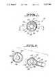
- FIG. 1is an end view of a clip ring and a spring preventer combination assembled together and on a shaft, according to the invention.
- FIG. 2is an exploded perspective view of the elements shown in FIG. 1.
- FIG. 3illustrates a typical installation for a clip ring and clip ring spread preventer according to the invention.
- FIG. 4shows the location of such an installation in association with a drive motor.
- the present inventionconcerns an assembly 10 which in its most basic elements comprises the shaft 12 on which the invention is disposed, the clip ring 20 to be held on the shaft and the clip ring spread preventer or retainer 40.
- the shaft 12may be a standard drive shaft driven by an electric motor 14.
- a groove 16is defined in the shaft, e.g. by milling, for receiving the spring clip 20.
- the shaft 12has a constant outer diameter and at the groove 16, the outer diameter is reduced by the depth of the groove.
- the shaft 12is a standard drive shaft driven in the usual manner by the motor 14. Further details of the shaft 12 are considered below with reference to the illustrated application for the shaft.
- the clip ring 20is of standard design. It is not a complete circle or ring. It is comprised of metal and is thick and heavy enough to be stiff and resilient while being sufficiently flexible to be mounted in and removed from the shaft groove 16.
- the clip ring 20includes the flexible but resilient web 22, which is out of direct contact with the shaft and is thin enough as to be flexed when the clip is placed on and removed from the shaft 12.
- the webis connected with the sides 24, 25 of the clip ring which are considerably wider than the web 22 and are inflexible.
- the sides 24, 25 of the clip ringare for placement on the opposite sides of an object, typically the shaft 12.
- the outer peripheral surfaces 26 of the sidesare together circular in shape to cooperate with the below described retainer 40. Other shapes may be used for the outer peripheral surfaces 26, even a straight wall shape, and the internal periphery of the retainer or spread preventer 40 would be correspondingly shaped.
- the inner peripheries 27 of the sides 24, 25are shaped internally to wrap sufficiently around the shaft 12 that they hold the clip ring 20 to the shaft once it is installed in the groove, yet the sides are spaced apart sufficiently between their free ends 28, 29 that the clip ring can be pushed radially onto the shaft at the groove and can be removed therefrom radially with only slight deformation of the resilient web 22.
- the retainer or spread preventer 40 of the present inventionis illustrated as cup shaped, including an annular peripheral ring portion 42 having an annular, internal, radially inwardly facing surface 44 that prevents the clip ring from spreading.
- the cup shaped retainer 40also includes an axial end wall or surface 46 through which passes an opening 48 that is of approximately the same diameter as the diameter of the shaft 12, so that the retainer can be slid along the shaft and so that there is substantially no clearance between the interior of the opening 48 and the shaft 12.
- the wall 46 of the retainer 40is next to the groove 16, but not in it.
- the end wall 46 of the cup washer 40prevents deformation of the clip ring axially along the shaft 12 while the internal surface 44 prevents spread of the clip ring sides 24, 25 radially outwardly.
- the external periphery 26 of the sides of the clip ringis shown as circular and the internal periphery 44 of the annular ring 42 is correspondingly rounded and of substantially the same diameter as the external periphery 26 so that spread of the clip ring will be prevented.
- the retainer 40is open on one axial side.
- the clip ringis initially axially outside the retainer to enable the clip ring sides to be spread sufficiently to be positioned on the shaft and is later outside the retainer to enable the clip ring sides to be removed from the shaft. After being mounted on the shaft, the clip ring is moved axially into the open side of the retainer and against its closed end wall 46, and the retainer prevents spreading of the clip ring while it is inside the retainer.
- the shape of the internal periphery of the clip ringwould be correspondingly modified so that the internal periphery 44 would still press against the external periphery of the clip ring and prevent the spreading of its sides.
- FIGS. 3 and 4An application for the clip ring and its spread preventer or retainer is illustrated in FIGS. 3 and 4.
- the shaft 12has a threaded end portion 52 on which the internally threaded nut 54 is to be tightened.
- the nut 54When the nut 54 is tightened on the thread 52, it draws the shaft axially to the right in FIGS. 3 and 4. Means are needed for preventing the shaft from so shifting beyond a specified amount.
- the shaftis supported for rotation in the standard bearing 58.
- the axially outer side 59 of the bearing 58defines the abutment past which the combined assembly 10 is not to be moved.
- the bearing 58is supported by washer and spacer 62 at the appropriate distance from the support plate 56.
- the spread preventer or retainer 40 of the present inventionis assembled onto the shaft 12 so that its supporting end wall 46 abuts the side 59 of the housing of the bearing 58.
- the peripheral ring 42 around the preventer/retaineris abutted by the external periphery 26 of the clip ring sides when the force on the shaft 12 exceeds a predetermined level. That abutment prevents further spreading and radial outward movement of the clip ring, holding it in the groove 16. Further, because the end wall 46 extends inward to the surface of the shaft 12 at its opening 48, the internal peripheral edge 27 of the clip ring cannot be deformed out of the groove along the shaft or into the inside of the bearing and cannot be bent.
- the cup washer 40combines with the clip ring 20 to define a permanent shoulder system 10.
- FIG. 4shows a typical motor and motor shaft installation, which is not described in detail because that installation is optional.
- One skilled in the artwould recognize the various stationary and rotary components in this typical installation where the invention might be employed.
Landscapes
- Engineering & Computer Science (AREA)
- General Engineering & Computer Science (AREA)
- Mechanical Engineering (AREA)
- Snaps, Bayonet Connections, Set Pins, And Snap Rings (AREA)
- Clamps And Clips (AREA)
Abstract
Description
Claims (6)
Priority Applications (2)
| Application Number | Priority Date | Filing Date | Title |
|---|---|---|---|
| US07/690,664US5127764A (en) | 1991-04-24 | 1991-04-24 | Clip ring spread preventer |
| CA002066514ACA2066514C (en) | 1991-04-24 | 1992-04-21 | Clip ring spread preventer |
Applications Claiming Priority (1)
| Application Number | Priority Date | Filing Date | Title |
|---|---|---|---|
| US07/690,664US5127764A (en) | 1991-04-24 | 1991-04-24 | Clip ring spread preventer |
Publications (1)
| Publication Number | Publication Date |
|---|---|
| US5127764Atrue US5127764A (en) | 1992-07-07 |
Family
ID=24773407
Family Applications (1)
| Application Number | Title | Priority Date | Filing Date |
|---|---|---|---|
| US07/690,664Expired - LifetimeUS5127764A (en) | 1991-04-24 | 1991-04-24 | Clip ring spread preventer |
Country Status (2)
| Country | Link |
|---|---|
| US (1) | US5127764A (en) |
| CA (1) | CA2066514C (en) |
Cited By (29)
| Publication number | Priority date | Publication date | Assignee | Title |
|---|---|---|---|---|
| US5329887A (en)* | 1992-04-03 | 1994-07-19 | Vision Sciences, Incorporated | Endoscope control assembly with removable control knob/brake assembly |
| US5367798A (en)* | 1993-02-04 | 1994-11-29 | Indresco Inc. | Connector pin assembly for bucket rigging |
| US5393162A (en)* | 1993-02-24 | 1995-02-28 | Nissen; Carl-Erik M. | Pivoting joint assembly |
| USD370604S (en) | 1994-11-23 | 1996-06-11 | The Budd Company | Push nut fastener |
| US5772159A (en)* | 1996-08-30 | 1998-06-30 | Fki Industries, Inc. | Conduit end fitting |
| US5816732A (en)* | 1997-02-05 | 1998-10-06 | Nissen; Carl-Erik M. | Cable connection device |
| US20030053857A1 (en)* | 2001-09-18 | 2003-03-20 | Anderson Jeffrey D. | Spring leg shaft retainer |
| USD487390S1 (en) | 2002-10-15 | 2004-03-09 | Chubu Bearing Kabushikikaisha | Retaining ring for shaft |
| US6792823B2 (en)* | 2000-03-31 | 2004-09-21 | Brother Kogyo Kabushiki Kaisha | Gear drive mechanism for office products |
| US6845644B1 (en) | 2003-08-21 | 2005-01-25 | James D. Buckner | Locking assembly |
| US20050019133A1 (en)* | 2003-07-21 | 2005-01-27 | Allen Joseph R. | Mounting device for securing an electronic device to an equipment rack |
| USD514431S1 (en)* | 2004-04-26 | 2006-02-07 | Chubu Bearing Kabushikikaisha | Retaining ring for shaft |
| US20060257230A1 (en)* | 2005-05-13 | 2006-11-16 | Kouichi Tanaka | Retaining ring for shaft |
| USD540153S1 (en) | 2005-04-01 | 2007-04-10 | Chubu Bearing Kabushikikaisha | Retaining ring for a shaft |
| US20070273163A1 (en)* | 2006-05-24 | 2007-11-29 | Gurtatowski Craig W | Door handle system |
| US20080080934A1 (en)* | 2006-09-29 | 2008-04-03 | Eliott Nelson Duffney | Non-intrusive vapor collection apparatus |
| US20100178103A1 (en)* | 2009-01-09 | 2010-07-15 | James Raszkowski | Tapered retaining ring to reduce bearing race movement |
| WO2010040610A3 (en)* | 2008-10-10 | 2010-11-11 | Robert Bosch Gmbh | Mounting bracket for fixing an armature shaft bearing of an electric motor |
| WO2014090786A1 (en)* | 2012-12-13 | 2014-06-19 | Hilti Aktiengesellschaft | Tool holder |
| US8770315B2 (en) | 2010-05-25 | 2014-07-08 | Makita Corporation | Impact tool |
| US20150308488A1 (en)* | 2012-12-13 | 2015-10-29 | Mack Trucks, Inc. | Retaining ring retention system and method |
| US20160169365A1 (en)* | 2014-12-15 | 2016-06-16 | Robert Bosch Gmbh | Handheld tool device |
| USD776998S1 (en)* | 2012-08-21 | 2017-01-24 | Orbit Irrigation Products, Inc. | Conduit removal tool |
| WO2017186240A1 (en)* | 2016-04-27 | 2017-11-02 | Bühler Motor GmbH | Actuator with securing means against radial removal of a securing element, such as, for example, a securing disc, a securing pin, etc. |
| US20190211878A1 (en)* | 2018-01-05 | 2019-07-11 | Valeo Systèmes d'Essuyage | Securing element for a bearing element |
| US20210180613A1 (en)* | 2018-06-29 | 2021-06-17 | Grundfos Holding A/S | Pump |
| WO2021165265A1 (en)* | 2020-02-18 | 2021-08-26 | Punch Powertrain N.V. | A retaining element, a shaft assembly and methods for assembling or disassembling the shaft assembly |
| US11251678B2 (en)* | 2019-01-24 | 2022-02-15 | Dy Auto Corporation | Small-sized motor apparatus for vehicle provided with improved shaft thrust gap prevention structure |
| US11287028B2 (en)* | 2018-05-07 | 2022-03-29 | Schaeffler Technologies AG & Co. KG | Assembly for securing the axial position of a sun gear of a planetary gearing stage on a rotor shaft of an electrical machine, and use of such an assembly |
Citations (12)
| Publication number | Priority date | Publication date | Assignee | Title |
|---|---|---|---|---|
| US372883A (en)* | 1887-11-08 | Clothes-rack attachment | ||
| US1181303A (en)* | 1916-01-27 | 1916-05-02 | Frank A Froehlich | Mounting for ladder-rungs. |
| US2026454A (en)* | 1933-01-10 | 1935-12-31 | Seidel & Naumann Ag | Locking disk |
| US2210811A (en)* | 1939-09-16 | 1940-08-06 | Edmund V Kelpsch | Shaft coupling |
| US2592942A (en)* | 1950-11-24 | 1952-04-15 | Brunson Instr Co | Dustproof leveling screw |
| US2945712A (en)* | 1957-04-17 | 1960-07-19 | Gen Motors Corp | Hub and shaft arrangement |
| US3340760A (en)* | 1965-05-05 | 1967-09-12 | Markite Corp | Means for preventing axial movement of a shaft or stud |
| US3595123A (en)* | 1969-08-25 | 1971-07-27 | Waldes Kohinoor Inc | Radial assembly-tire spring retaining rings |
| US4040602A (en)* | 1976-04-01 | 1977-08-09 | Foster Sr Howard F | Tensioning anchor |
| US4182578A (en)* | 1978-03-24 | 1980-01-08 | Caterpillar Tractor Co. | Keeper assembly |
| US4405251A (en)* | 1980-03-06 | 1983-09-20 | Miller Fluid Power Corporation | Retaining ring locking device |
| US4757751A (en)* | 1987-05-26 | 1988-07-19 | Ingersoll-Rand Company | Ram couling and cylinder end seal assembly for high pressure cylinder |
- 1991
- 1991-04-24USUS07/690,664patent/US5127764A/ennot_activeExpired - Lifetime
- 1992
- 1992-04-21CACA002066514Apatent/CA2066514C/ennot_activeExpired - Lifetime
Patent Citations (12)
| Publication number | Priority date | Publication date | Assignee | Title |
|---|---|---|---|---|
| US372883A (en)* | 1887-11-08 | Clothes-rack attachment | ||
| US1181303A (en)* | 1916-01-27 | 1916-05-02 | Frank A Froehlich | Mounting for ladder-rungs. |
| US2026454A (en)* | 1933-01-10 | 1935-12-31 | Seidel & Naumann Ag | Locking disk |
| US2210811A (en)* | 1939-09-16 | 1940-08-06 | Edmund V Kelpsch | Shaft coupling |
| US2592942A (en)* | 1950-11-24 | 1952-04-15 | Brunson Instr Co | Dustproof leveling screw |
| US2945712A (en)* | 1957-04-17 | 1960-07-19 | Gen Motors Corp | Hub and shaft arrangement |
| US3340760A (en)* | 1965-05-05 | 1967-09-12 | Markite Corp | Means for preventing axial movement of a shaft or stud |
| US3595123A (en)* | 1969-08-25 | 1971-07-27 | Waldes Kohinoor Inc | Radial assembly-tire spring retaining rings |
| US4040602A (en)* | 1976-04-01 | 1977-08-09 | Foster Sr Howard F | Tensioning anchor |
| US4182578A (en)* | 1978-03-24 | 1980-01-08 | Caterpillar Tractor Co. | Keeper assembly |
| US4405251A (en)* | 1980-03-06 | 1983-09-20 | Miller Fluid Power Corporation | Retaining ring locking device |
| US4757751A (en)* | 1987-05-26 | 1988-07-19 | Ingersoll-Rand Company | Ram couling and cylinder end seal assembly for high pressure cylinder |
Cited By (44)
| Publication number | Priority date | Publication date | Assignee | Title |
|---|---|---|---|---|
| US5329887A (en)* | 1992-04-03 | 1994-07-19 | Vision Sciences, Incorporated | Endoscope control assembly with removable control knob/brake assembly |
| US5367798A (en)* | 1993-02-04 | 1994-11-29 | Indresco Inc. | Connector pin assembly for bucket rigging |
| US5393162A (en)* | 1993-02-24 | 1995-02-28 | Nissen; Carl-Erik M. | Pivoting joint assembly |
| USD370604S (en) | 1994-11-23 | 1996-06-11 | The Budd Company | Push nut fastener |
| US5772159A (en)* | 1996-08-30 | 1998-06-30 | Fki Industries, Inc. | Conduit end fitting |
| US5816732A (en)* | 1997-02-05 | 1998-10-06 | Nissen; Carl-Erik M. | Cable connection device |
| US6792823B2 (en)* | 2000-03-31 | 2004-09-21 | Brother Kogyo Kabushiki Kaisha | Gear drive mechanism for office products |
| US20030053857A1 (en)* | 2001-09-18 | 2003-03-20 | Anderson Jeffrey D. | Spring leg shaft retainer |
| USD487390S1 (en) | 2002-10-15 | 2004-03-09 | Chubu Bearing Kabushikikaisha | Retaining ring for shaft |
| US20050019133A1 (en)* | 2003-07-21 | 2005-01-27 | Allen Joseph R. | Mounting device for securing an electronic device to an equipment rack |
| US6955512B2 (en)* | 2003-07-21 | 2005-10-18 | Hewlett-Packard Development Company, L.P. | Mounting device for securing an electronic device to an equipment rack |
| US6845644B1 (en) | 2003-08-21 | 2005-01-25 | James D. Buckner | Locking assembly |
| USD514431S1 (en)* | 2004-04-26 | 2006-02-07 | Chubu Bearing Kabushikikaisha | Retaining ring for shaft |
| USD540153S1 (en) | 2005-04-01 | 2007-04-10 | Chubu Bearing Kabushikikaisha | Retaining ring for a shaft |
| US20060257230A1 (en)* | 2005-05-13 | 2006-11-16 | Kouichi Tanaka | Retaining ring for shaft |
| US20070273163A1 (en)* | 2006-05-24 | 2007-11-29 | Gurtatowski Craig W | Door handle system |
| US20080080934A1 (en)* | 2006-09-29 | 2008-04-03 | Eliott Nelson Duffney | Non-intrusive vapor collection apparatus |
| US7386957B2 (en) | 2006-09-29 | 2008-06-17 | Xerox Corporation | Non-intrusive vapor collection apparatus |
| WO2010040610A3 (en)* | 2008-10-10 | 2010-11-11 | Robert Bosch Gmbh | Mounting bracket for fixing an armature shaft bearing of an electric motor |
| CN102177641A (en)* | 2008-10-10 | 2011-09-07 | 罗伯特·博世有限公司 | Mounting bracket for fixing an armature shaft bearing of an electric motor |
| US20100178103A1 (en)* | 2009-01-09 | 2010-07-15 | James Raszkowski | Tapered retaining ring to reduce bearing race movement |
| US8747014B2 (en)* | 2009-01-09 | 2014-06-10 | Allison Transmission, Inc. | Tapered retaining ring to reduce bearing race movement |
| EP2390049B1 (en)* | 2010-05-25 | 2016-01-20 | Makita Corporation | Impact Tool |
| US8770315B2 (en) | 2010-05-25 | 2014-07-08 | Makita Corporation | Impact tool |
| USD776998S1 (en)* | 2012-08-21 | 2017-01-24 | Orbit Irrigation Products, Inc. | Conduit removal tool |
| WO2014090786A1 (en)* | 2012-12-13 | 2014-06-19 | Hilti Aktiengesellschaft | Tool holder |
| US20150308488A1 (en)* | 2012-12-13 | 2015-10-29 | Mack Trucks, Inc. | Retaining ring retention system and method |
| US9933005B2 (en)* | 2012-12-13 | 2018-04-03 | Volvo Lastvagnar Ab | Retaining ring retention system and method |
| US10746277B2 (en)* | 2014-12-15 | 2020-08-18 | Robert Bosch Gmbh | Handheld tool device with bracket holder unit for connection of two gear housings |
| US11333237B2 (en)* | 2014-12-15 | 2022-05-17 | Robert Bosch Gmbh | Handheld tool device |
| US20160169365A1 (en)* | 2014-12-15 | 2016-06-16 | Robert Bosch Gmbh | Handheld tool device |
| US10781866B2 (en) | 2016-04-27 | 2020-09-22 | Bühler Motor GmbH | Actuator with means against radial removal of securing element |
| CN109075656A (en)* | 2016-04-27 | 2018-12-21 | 标立电机有限公司 | An actuator with a locking device that prevents radial disengagement of locking elements such as locking washers, locking pins, etc. |
| WO2017186240A1 (en)* | 2016-04-27 | 2017-11-02 | Bühler Motor GmbH | Actuator with securing means against radial removal of a securing element, such as, for example, a securing disc, a securing pin, etc. |
| US10641339B2 (en)* | 2018-01-05 | 2020-05-05 | Valeo Systèmes d'Essuyage | Securing element for a bearing element |
| US20190211878A1 (en)* | 2018-01-05 | 2019-07-11 | Valeo Systèmes d'Essuyage | Securing element for a bearing element |
| US11287028B2 (en)* | 2018-05-07 | 2022-03-29 | Schaeffler Technologies AG & Co. KG | Assembly for securing the axial position of a sun gear of a planetary gearing stage on a rotor shaft of an electrical machine, and use of such an assembly |
| US20210180613A1 (en)* | 2018-06-29 | 2021-06-17 | Grundfos Holding A/S | Pump |
| US11719258B2 (en)* | 2018-06-29 | 2023-08-08 | Grundfos Holding A/S | Pump |
| US11251678B2 (en)* | 2019-01-24 | 2022-02-15 | Dy Auto Corporation | Small-sized motor apparatus for vehicle provided with improved shaft thrust gap prevention structure |
| WO2021165265A1 (en)* | 2020-02-18 | 2021-08-26 | Punch Powertrain N.V. | A retaining element, a shaft assembly and methods for assembling or disassembling the shaft assembly |
| BE1028066B1 (en)* | 2020-02-18 | 2021-09-15 | Punch Powertrain | Shaft composition, retaining element and methods |
| CN115516216A (en)* | 2020-02-18 | 2022-12-23 | 邦奇动力有限责任公司 | Retaining elements, shaft assemblies and methods for assembling or disassembling shaft assemblies |
| US12203498B2 (en) | 2020-02-18 | 2025-01-21 | Punch Powertrain E-Vehicles Nv | Retaining element, a shaft assembly and methods for assembling or disassembling the shaft assembly |
Also Published As
| Publication number | Publication date |
|---|---|
| CA2066514A1 (en) | 1992-10-25 |
| CA2066514C (en) | 1995-10-03 |
Similar Documents
| Publication | Publication Date | Title |
|---|---|---|
| US5127764A (en) | Clip ring spread preventer | |
| US3537555A (en) | Overrunning roller clutch | |
| US9016746B2 (en) | Train axle assembly | |
| US6666583B2 (en) | Bearing retention assembly having cam chamfered bearing race ring | |
| KR100305512B1 (en) | Clamp Type Locking Device for Seat Position Adjustment | |
| US5711618A (en) | Bearing assembly with end cap | |
| US4778041A (en) | Rolling member | |
| FI71188C (en) | FRIKTIONSKOPPLING | |
| EP0099136B1 (en) | Pressed-in anti-rotation lugs for mechanical face seals | |
| EA003684B1 (en) | Connecting fitting with an elastic ring as a stop | |
| US6368039B2 (en) | Dual function retainer clip | |
| GB2259962A (en) | Torque limiter | |
| US5429396A (en) | Snap-in assemblies and retaining means therefor | |
| EP0388378B1 (en) | Device for assembling a bearing on a shaft | |
| US2836474A (en) | Sealing structure for reciprocating elements | |
| US4077504A (en) | Self-centering clutch thrust bearing | |
| US6773214B2 (en) | Snap ring retention system | |
| US3547238A (en) | Freewheel device | |
| JP2005121230A (en) | System for fixing rolling bearing in axial direction | |
| JPS62132033A (en) | Sealing device for bearing,particularly, rod end bearing with outer ring having slit | |
| GB2313417A (en) | Cover for bearings | |
| US5979626A (en) | One-way clutch | |
| JP3657334B2 (en) | Roller clutch | |
| US3086270A (en) | Hose clamp and method of assembly | |
| CA2244622C (en) | Motor shaft assembly method |
Legal Events
| Date | Code | Title | Description |
|---|---|---|---|
| AS | Assignment | Owner name:SHOP-VAC CORPORATION A CORPORATION OF NJ, PENNS Free format text:ASSIGNMENT OF ASSIGNORS INTEREST.;ASSIGNOR:BAER, MARK;REEL/FRAME:005687/0910 Effective date:19910418 | |
| STCF | Information on status: patent grant | Free format text:PATENTED CASE | |
| AS | Assignment | Owner name:FIRST UNION NATIONAL BANK OF NORTH CAROLINA, NORTH Free format text:ASSIGNMENT OF ASSIGNORS INTEREST;ASSIGNOR:SHOPVAC CORPORATION;REEL/FRAME:006924/0139 Effective date:19940201 | |
| FEPP | Fee payment procedure | Free format text:PAYOR NUMBER ASSIGNED (ORIGINAL EVENT CODE: ASPN); ENTITY STATUS OF PATENT OWNER: LARGE ENTITY | |
| FPAY | Fee payment | Year of fee payment:4 | |
| AS | Assignment | Owner name:SHOP VAC CORPORATION, PENNSYLVANIA Free format text:RELEASE OF PATENT COLLATERAL;ASSIGNOR:FIRST UNION NATIONAL BANK OF NORTH CAROLINA;REEL/FRAME:008274/0624 Effective date:19960930 | |
| AS | Assignment | Owner name:LEHMAN COMMERCIAL PAPER INC., AS ADMINISTRATIVE AG Free format text:SECURITY AGREEMENT;ASSIGNOR:SHOP VAC CORPORATION;REEL/FRAME:010231/0454 Effective date:19990708 | |
| FEPP | Fee payment procedure | Free format text:PAYER NUMBER DE-ASSIGNED (ORIGINAL EVENT CODE: RMPN); ENTITY STATUS OF PATENT OWNER: LARGE ENTITY Free format text:PAYOR NUMBER ASSIGNED (ORIGINAL EVENT CODE: ASPN); ENTITY STATUS OF PATENT OWNER: LARGE ENTITY | |
| FPAY | Fee payment | Year of fee payment:8 | |
| AS | Assignment | Owner name:WACHOVIA BANK, N.A., AS ADMINISTRATIVE AGENT, NORT Free format text:NOTICE OF GRANT OF SECURITY INTEREST;ASSIGNOR:SHOP VAC CORPORATION;REEL/FRAME:013727/0608 Effective date:20021217 | |
| FPAY | Fee payment | Year of fee payment:12 | |
| AS | Assignment | Owner name:WACHOVIA BANK, NATIONAL ASSOCIATION, AS ADMINISTRA Free format text:SECURITY AGREEMENT;ASSIGNOR:SHOP VAC CORPORATION;REEL/FRAME:019668/0529 Effective date:20070618 |