US5125940A - In-line air filter apparatus - Google Patents
In-line air filter apparatusDownload PDFInfo
- Publication number
- US5125940A US5125940AUS07/657,662US65766291AUS5125940AUS 5125940 AUS5125940 AUS 5125940AUS 65766291 AUS65766291 AUS 65766291AUS 5125940 AUS5125940 AUS 5125940A
- Authority
- US
- United States
- Prior art keywords
- air filter
- air
- filter element
- housing
- disposed
- Prior art date
- Legal status (The legal status is an assumption and is not a legal conclusion. Google has not performed a legal analysis and makes no representation as to the accuracy of the status listed.)
- Expired - Lifetime
Links
Images

Classifications
- B—PERFORMING OPERATIONS; TRANSPORTING
- B01—PHYSICAL OR CHEMICAL PROCESSES OR APPARATUS IN GENERAL
- B01D—SEPARATION
- B01D46/00—Filters or filtering processes specially modified for separating dispersed particles from gases or vapours
- B01D46/0002—Casings; Housings; Frame constructions
- B01D46/0012—In-line filters
- F—MECHANICAL ENGINEERING; LIGHTING; HEATING; WEAPONS; BLASTING
- F02—COMBUSTION ENGINES; HOT-GAS OR COMBUSTION-PRODUCT ENGINE PLANTS
- F02M—SUPPLYING COMBUSTION ENGINES IN GENERAL WITH COMBUSTIBLE MIXTURES OR CONSTITUENTS THEREOF
- F02M35/00—Combustion-air cleaners, air intakes, intake silencers, or induction systems specially adapted for, or arranged on, internal-combustion engines
- F02M35/02—Air cleaners
- F02M35/0201—Housings; Casings; Frame constructions; Lids; Manufacturing or assembling thereof
- F02M35/0202—Manufacturing or assembling; Materials for air cleaner housings
- F02M35/0203—Manufacturing or assembling; Materials for air cleaner housings by using clamps, catches, locks or the like, e.g. for disposable plug-in filter cartridges
- F—MECHANICAL ENGINEERING; LIGHTING; HEATING; WEAPONS; BLASTING
- F02—COMBUSTION ENGINES; HOT-GAS OR COMBUSTION-PRODUCT ENGINE PLANTS
- F02M—SUPPLYING COMBUSTION ENGINES IN GENERAL WITH COMBUSTIBLE MIXTURES OR CONSTITUENTS THEREOF
- F02M35/00—Combustion-air cleaners, air intakes, intake silencers, or induction systems specially adapted for, or arranged on, internal-combustion engines
- F02M35/02—Air cleaners
- F02M35/024—Air cleaners using filters, e.g. moistened
- F—MECHANICAL ENGINEERING; LIGHTING; HEATING; WEAPONS; BLASTING
- F02—COMBUSTION ENGINES; HOT-GAS OR COMBUSTION-PRODUCT ENGINE PLANTS
- F02M—SUPPLYING COMBUSTION ENGINES IN GENERAL WITH COMBUSTIBLE MIXTURES OR CONSTITUENTS THEREOF
- F02M35/00—Combustion-air cleaners, air intakes, intake silencers, or induction systems specially adapted for, or arranged on, internal-combustion engines
- F02M35/10—Air intakes; Induction systems
- F02M35/10006—Air intakes; Induction systems characterised by the position of elements of the air intake system in direction of the air intake flow, i.e. between ambient air inlet and supply to the combustion chamber
- F02M35/10019—Means upstream of the fuel injection system, carburettor or plenum chamber
- F—MECHANICAL ENGINEERING; LIGHTING; HEATING; WEAPONS; BLASTING
- F02—COMBUSTION ENGINES; HOT-GAS OR COMBUSTION-PRODUCT ENGINE PLANTS
- F02M—SUPPLYING COMBUSTION ENGINES IN GENERAL WITH COMBUSTIBLE MIXTURES OR CONSTITUENTS THEREOF
- F02M35/00—Combustion-air cleaners, air intakes, intake silencers, or induction systems specially adapted for, or arranged on, internal-combustion engines
- F02M35/10—Air intakes; Induction systems
- F02M35/10091—Air intakes; Induction systems characterised by details of intake ducts: shapes; connections; arrangements
- F02M35/10118—Air intakes; Induction systems characterised by details of intake ducts: shapes; connections; arrangements with variable cross-sections of intake ducts along their length; Venturis; Diffusers
- F—MECHANICAL ENGINEERING; LIGHTING; HEATING; WEAPONS; BLASTING
- F02—COMBUSTION ENGINES; HOT-GAS OR COMBUSTION-PRODUCT ENGINE PLANTS
- F02M—SUPPLYING COMBUSTION ENGINES IN GENERAL WITH COMBUSTIBLE MIXTURES OR CONSTITUENTS THEREOF
- F02M35/00—Combustion-air cleaners, air intakes, intake silencers, or induction systems specially adapted for, or arranged on, internal-combustion engines
- F02M35/16—Combustion-air cleaners, air intakes, intake silencers, or induction systems specially adapted for, or arranged on, internal-combustion engines characterised by use in vehicles
- F02M35/161—Arrangement of the air intake system in the engine compartment, e.g. with respect to the bonnet or the vehicle front face
- F—MECHANICAL ENGINEERING; LIGHTING; HEATING; WEAPONS; BLASTING
- F05—INDEXING SCHEMES RELATING TO ENGINES OR PUMPS IN VARIOUS SUBCLASSES OF CLASSES F01-F04
- F05C—INDEXING SCHEME RELATING TO MATERIALS, MATERIAL PROPERTIES OR MATERIAL CHARACTERISTICS FOR MACHINES, ENGINES OR PUMPS OTHER THAN NON-POSITIVE-DISPLACEMENT MACHINES OR ENGINES
- F05C2225/00—Synthetic polymers, e.g. plastics; Rubber
- F05C2225/08—Thermoplastics
Definitions
- the present inventionis directed generally to air filters, and more particularly to an improved in-line air filter apparatus for providing filtered air having reduced turbulence to the engine air intake hose of an internal combustion engine and thereby reducing the pressure drop across the air filter apparatus.
- Intake air noise reductionis a substantial concern to automotive engineers because any additional air noise present adds a further component of noise to the noise level already emanating from the hood of the automobile from other elements of the engine, and is thus audibly further detectable by the occupants of the passenger compartment.
- Pressure drop across the air filter intake systemis also a primary concern of automotive engineers, due to the inversely proportional relationship between the air flow restriction and the efficiency of the engine. As the air flow restriction increases in the air induction system, the horsepower and fuel economy of the engine are commensurately decreased.
- the improved in-line air filter apparatus of the present inventionto alleviate materially these difficulties, defects, deficiencies of the prior art.
- the improved in-line air filter apparatus of the present inventionpresents the advantage of providing less turbulent air by means of substantially improved air flow conditions.
- a smooth transition from the smaller ambient air hose diameter to the larger housing diameter, a hemispherical end closure cap, and a filter element outlet having a diameter equal to the diameter of the engine air intake hose (as described more completely, infra)all serve to minimize turbulence, and hence air flow restriction.
- the in-line construction of the air filter apparatus of the present inventionpermits the apparatus to be mounted co-axially with the air induction hose which further avoids drastic changes in the direction of air flow. The result is a more quiet and more efficient operation of the engine.
- the present inventionincludes in one preferred embodiment a substantially cylindrical air filter housing disposed in-line on the engine air intake hose of an internal combustion engine, with a tubular air filter element longitudinally disposed therein.
- the tubular shape of the air filterpermits the air stream to be directed through the body of the tubular filter element and into the air intake hose by blocking one end of the tubular air filter element, and retaining the opposite end in open configuration.
- such tubular air filter elementhas a closed axial end disposed upstream of an open axial downstream end, with the open end having a size and shape substantially congruent with the size and shape of the engine air intake hose of the internal combustion engine for minimizing the turbulence of the filtered air supplied thereto.
- the closed upstream end of the tubular air filter elementhas an annular shaped air inlet portion for directing air longitudinally and inwardly through the walls of the body of the tubular air filter element.
- FIG. 1is a side elevational view of the improved in-line air filter apparatus of the present invention as installed on the engine intake hose of an internal combustion engine and showing the air filter housing thereof partially sectioned away to reveal the tubular air filter element and accompanying elements disposed within the interior of such housing;
- FIG. 2is an enlarged view of the improved in-line air filter apparatus as shown in FIG. 1, and as likewise partially sectioned, with the top longitudinal half of the drawing showing the exterior of the air filter housing, and the bottom longitudinal half of the drawing comprising a longitudinal cross-sectional view to show the details of the tubular air filter element including the filtration medium support, the filtration medium (schematically shown), and the air filtration element positioning, centering, and support means, along with the there depicted hemispherical end cap to close the closed end of the tubular air filter element in order to direct the flow of air therearound for further directing such air to flow inwardly through the body of the tubular filter medium into the lumen thereof, for thereupon exiting at the open end of the filter into the engine air intake hose, and which in the embodiment of FIG. 2 further includes a venturi apparatus;
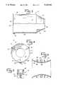
- FIG. 3is a partially sectioned view of an embodiment of the improved in-line air filter apparatus of the present invention there showing a cylindrical air filter housing, and further showing at the bottom longitudinal half thereof the spring-loaded clip bracket disposed at and securing the downstream end of the air filter housing, and also showing the air filter element positioning means in the form of one of a plurality of triangular-shaped ribs disposed each in projecting array from the interior surface of the housing for holding, supporting and positioning the hemispherical end closure cap;
- FIG. 4is an end on view of the embodiment of FIG. 3 (slightly reduced in size) as viewed from the downstream (and there, open) end of the air filter housing, and showing an embodiment having three such air filter element centering projecting ribs as disposed on the interior surface of the frusto-conical portion of the air filter housing, and also showing on the exterior of the housing the brackets for holding the spring loaded clamps;
- FIG. 5is a greatly enlarged cross-sectional view of one bracket taken along line 5--5 of FIG. 4;
- FIG. 6is an enlarged longitudinal cross-sectional view of the venturi apparatus as shown in FIGS. 1 and 2, and in addition showing radially disposed O-ring holding brackets for sealingly mounting the venturi within the housing.
- the improved in-line air filter apparatus of the present inventionis directed to structures comprising various forms of an air filter apparatus which function to reduce the pressure drop across the entire air filter apparatus, and also which function to provide filtered air having reduced turbulence to the engine air intake hose of an internal combustion engine, such as may be used in a motor vehicle.
- the air filter apparatus of the present inventionincludes an air filter housing, which may be substantially cylindrical, but which may include a frusto-conical element thereof, or alternatively may be slightly tapered in overall shape.
- the air filter housing element of the present inventionhas an ambient air intake end at one end thereof and a filtered air outlet at the opposite end thereof.
- the air filter housingis adapted for connection to and disposition in-line on the engine air intake housing of the internal combustion engine.
- a tubular air filter elementis longitudinally disposed and enclosed within the preferably elongated air filter housing.
- the tubular air filter elementhas one closed axial end and an oppositely disposed axial end.
- the closed axial endis disposed upstream of the open axial downstream end.
- the open endhas a size and shape which is substantially congruent with the size and shape of the engine air intake hose of the internal combustion engine.
- the improved in-line air filter apparatus of the present inventionalso includes filtration media support means, which may be in the form of a mesh or an expanded metal screen.
- the filtration media support meansis disposed within the housing and adjacent the interior walls of the housing for flow of air therethrough and through the body of the tubular air filter element supported therefrom.
- the tubular air filter element of the in-line air filter apparatus of the present inventionhas associated therewith an end closure which is disposed at and closes the closed end of the air filter element to define an ambient air intake end of the filter element which is substantially annular in shape in end-on view.
- the air filtration media support meansin preferred embodiments also further defines at the open end of the tubular air filter element a filtered air output end of such tubular air filtration element which is substantially circular in shape in end-on view.
- the tubular shape of the body of filtration medium together with the end closure capco-operate to define a longitudinally and inwardly directed air flow path from the closed end to the open end of the tubular air filter element to direct the stream of air into, within and from the tubular air filter element as disposed within the housing.
- the air filtration media support meansis in preferred embodiments substantially cylindrical in shape and is disposed congruently with the preferably similarly shaped air filter housing.
- the diameter of such preferably cylindrical filtration medium support meansmay preferably be substantially the same diameter as that of the engine air intake hose, and such air filtration support means is disposed within the air filter housing to direct air smoothly and with minimum turbulence into the engine air intake hose.
- the filtration medium support meansalso preferably defines an air flow channel means disposed internally of the air filtration medium, and thus directs the filtered air to and into the engine air intake hose.
- the body of the tubular air filter elementmay comprise in a preferred embodiment a corrugated paper filter element which is cylindrical in overall shape.
- Such corrugated paper elementpreferably may have an exterior shape which fits snugly within the air filter housing.
- the end closure cap disposed at the upstream end of the tubular filter elementmay preferably be dome-shaped in order to present a substantially hemispherical shape to the flow of air into the ambient air intake of the air filter housing to minimize the restriction of air entering the ambient air end (i.e., the upstream end) and to deflect the entering ambient air efficiently around and past the dome-shaped end closure cap.
- the air filter housingmay also further include air filter element axial positioning means for positioning the longitudinal axis of the air filter element to coincide preferably with the longitudinal axis of the air filter housing.
- air filter element axial positioning meansmay include in preferred embodiments a plurality of air filter positioning projections attached to and projecting inwardly from the interior surface of the air filter housing, and in certain preferred embodiments from the frusto-conical portion thereof, and more preferably engaging the dome-shaped end cap for the closed, upstream end of the tubular air filter element.
- Such air filter positioning projectionsmay be essentially triangular in longitudinal cross-sectional shape.
- the air filter housingmay further include a housing end lid for closing the portion of the downstream end of the air filter housing which is disposed concentrically around the downstream and air exiting end thereof in order to direct the stream of filtered air into the engine air intake hose.
- Air filter apparatus 10is connected to the air intake hose 12 of an internal combustion engine 14 (partially shown) by means of clamps 15, and such air filter apparatus 10 is connected at the opposite end thereof to an ambient air intake 13 disposed at the front of the engine compartment 17, shown in partial section in FIG. 1.
- Air filter apparatus 10includes an air filter housing 16, which may be substantially cylindrical as shown in FIGS. 1-4 hereof, and includes a frusto-conical forward element 18, although other housing shapes including a slightly tapered shape are contemplated.
- Air filter housing element 16has an ambient air intake 20 at the upstream end 22 thereof and a filtered air outlet 24 at the downstream end 26 thereof.
- Ambient air intake 20is shown in FIG. 1 connected to ambient air intake hose 28 by means of a radial bead 30 and clamp 32 thereover.
- a tubular air filter schematically shown at 34is longitudinally disposed and enclosed within the elongated air filter housing 16.
- Such tubular air filter 34has one closed axial end 36 which is disposed upstream of an open axial downstream end 38.
- Open downstream end 38has a size and shape which is substantially congruent with the size and shape of engine air intake hose 12 of internal combustion engine 14 and functions to minimize the turbulence of the filtered air which is supplied to such internal combustion engine.
- a venturi extension housing 40is disposed between open axial downstream end 38 and engine air intake hose 12, as shown in FIGS. 1 and 2.
- Such venturi extension housing 40contains a venturi element 42 which is sealingly disposed therein by means of O-rings 44,44 disposed within O-ring support grooves 46 disposed radially upon O-ring support ribs 48.
- Stabilization ribs 50are disposed radially around the exterior 52 of venturi element 42 for providing stabilization thereto.
- Venturi element 42may or may not be used in alternative embodiments depending upon the need for crankcase vapor evacuation, and when present evacuates by means of a vacuum evacuation tube 54 for the PCV valve (not shown), and disposed on venturi extension housing 40 and through evacuation slits 55 in the wall of venturi element 40, in a manner known to those of ordinary skill in the art.
- venturi extension housing 40is dipicted as being essentially cylindrical, it may be slightly tapered in shape in certain alternative preferred embodiments.
- Improved in-line air filter apparatus 10also includes filtration media support means, which may be in the form of a filter support mesh 56.
- Filter support mesh 56is disposed within housing 16, and more particularly adjacent the interior walls 58 of housing 16 for flow of air therethrough and through the tubular air filter 34 supported therefrom.
- Tubular air filter 34includes an end closure cap 60 which is disposed at and closes closed end 22 of air filter 34 to define an ambient air intake end 62 of air filter 34 which is substantially annular in shape in end-on view.
- Filter support mesh 56also further defines at open end 24 of tubular air filter 34 a filtered air output end 64 of such tubular air filter 34 which is substantially circular in shape in end-on view.
- tubular air filter 34 and the end closure cap 60together function to define a longitudinally and inwardly directed air flow path shown in Arrows A-E on FIG. 2.
- ambient airenters ambient air intake 20 (at Arrow A) and is deflected around end closure cap 60 (at Arrow B) to the ambient air intake end 62 of air filter 34; then such air stream passes through the body 66 of air filter 34 through support mesh 56 thereof into the lumen of such tubular air filter (at Arrow C); whereupon, the now filtered air stream passes from the air filter 34 through downstream end 26 thereof, into venturi element 42 (at Arrow D) and therefrom into the engine air intake hose 12 (at Arrow E).
- Tubular air filter 34may comprise in preferred embodiments a corrugated paper filter element which is cylindrical in overall shape as shown in FIGS. 1 and 2.
- Such corrugated paper elementpreferably may have an exterior surface 68 which fits snugly within air filter interior walls 58.
- Air filter housing 16includes means for the purpose of axial positioning of the longitudinal axis of air filter 34 to coincide, as shown, with the longitudinal axis of air filter housing 16.
- Such air filter element axial positioning meansis shown in FIGS. 1, 2, 3 and 4 as comprising a plurality of air filter positioning projections 70 attached to and projecting inwardly from frusto-conical portion 18 of interior walls 58 of air filter housing 16, and engages end closure cap 60 for the closed, upstream end 22 of tubular air filter 34.
- Air filter housing 16also includes a housing end lid 72 for closing the portion of downstream end 24 of air filter housing 16 which is disposed concentrically around the downstream and air exiting end 24 thereof in order to direct the stream of filtered air into engine air intake hose 12 (see Arrows D and E).
- Housing end lid 72is shown as contiguous with venturi extension housing 40 in FIG. 2, but of course may be separately formed.
- Axial downstream end 38 of air filter 34is supported by a support bracket 35 which has an annular-shaped groove therein to accommodate and support such downstream end 38 of air filter 34, the upstream end 36 of which is supported by means of projections 70.
- Clips 74which are spring-loaded by means of springs 76 are disposed to secure housing end lid 72 upon downstream end 26 thereof. Clips 74 are supported by clip support brackets 76, as shown in FIG. 2 in particular. Each clip support bracket 76 has two side channels 78,78 for engagement of the ends of the springs 76 and front and rear support engagement surfaces 80,82.
- the clip support brackets 76may vary widely in structure, as is well known in the art.
- the various elements of the present inventionmay be made of various different materials.
- injection molded plasticis preferred for the various components comprising the housing element 16 thereof.
- End enclosure cap 60shown as a done-shaped structure in FIGS. 1 and 2, may likewise be made of molded plastic.
- the filtration medium support mesh 56is preferably formed of a metal mesh or screen-like material.
- the filter medium material 34per se, is preferably made of a fibrous material of appropriate porosity, and most preferably of filter paper.
- the pressure drop across the structure of the improved in-line air filtration apparatus 10 of the present inventionwas tested versus the pressure drop experienced with the presently used Chrysler XJ Panel air filter housing.
- the Chrysler XJ Panel air filter housingis reasonably typical of the housings presently utilized in regard to automotive and other internal combustion engines in the art.
- Such prior art housingsare designed, for the most part, to fit into the available space near the fender walls of the automobile, and consequently away from the engine. This remote location causes multiple air flow direction changes in piping the ambient air from the vehicle front through the air cleaner assembly to the throttle body. These directional changes result in turbulent flow conditions which contributed to increased pressure drop and/or noise level.
- the prior art Chrysler apparatusincludes an air filter housing which is substantially box-shaped.
- the lower half portion of the boxis separated from the upper half portion of the box by the filter medium.
- Ambient airtypically enters the lower portion of the box-shaped housing longitudinally at one end thereof, and is then deflected and directed upwardly through the filter element.
- the upwardly flowing air from the lower portion of the boxis further deflected from the top of the interior surface of the box and is finally exhausted laterally from the box in a direction which is substantially transverse to that of the initial ambient air entry into the lower portion of the box.
- such air flow in the prior art Chrysler apparatusabruptly enters, is deflected several times interiorly, and finally exits the filtration apparatus, all of which creates turbulent air flow conditions, which in turn contribute to increased pressure drop and increased noise level.
- Such abrupt entries, deflections and exits of the air floware caused by the substantially flat surfaces of the boxed-shaped housing of the prior art Chrysler apparatus.
- the flat surfaces of the prior art Chrysler apparatusincrease noise levels when expanding and contracting during pressure pulsations, such pressure pulsations being caused by variations in engine air demand.
Landscapes
- Engineering & Computer Science (AREA)
- Chemical & Material Sciences (AREA)
- Combustion & Propulsion (AREA)
- Mechanical Engineering (AREA)
- General Engineering & Computer Science (AREA)
- Manufacturing & Machinery (AREA)
- Chemical Kinetics & Catalysis (AREA)
- Filtering Of Dispersed Particles In Gases (AREA)
Abstract
Description
______________________________________ Pressure Drop (in. H.sub.2 O) Air Flow (scf m) Apparatus Hereof Chrysler XJ ______________________________________ 100 1.6 1.8 200 6.3 6.6 300 12.6 14.3 330 15.4 17.3 400 22.9 25.7 ______________________________________
Claims (20)
Priority Applications (1)
| Application Number | Priority Date | Filing Date | Title |
|---|---|---|---|
| US07/657,662US5125940A (en) | 1991-02-19 | 1991-02-19 | In-line air filter apparatus |
Applications Claiming Priority (1)
| Application Number | Priority Date | Filing Date | Title |
|---|---|---|---|
| US07/657,662US5125940A (en) | 1991-02-19 | 1991-02-19 | In-line air filter apparatus |
Publications (1)
| Publication Number | Publication Date |
|---|---|
| US5125940Atrue US5125940A (en) | 1992-06-30 |
Family
ID=24638122
Family Applications (1)
| Application Number | Title | Priority Date | Filing Date |
|---|---|---|---|
| US07/657,662Expired - LifetimeUS5125940A (en) | 1991-02-19 | 1991-02-19 | In-line air filter apparatus |
Country Status (1)
| Country | Link |
|---|---|
| US (1) | US5125940A (en) |
Cited By (35)
| Publication number | Priority date | Publication date | Assignee | Title |
|---|---|---|---|---|
| US5275636A (en)* | 1992-06-04 | 1994-01-04 | Vortox Company | Air cleaner for internal combustion engine |
| US5320657A (en)* | 1993-04-30 | 1994-06-14 | Dana Corporation | Staggered short pleat air filter |
| US5472463A (en)* | 1994-06-14 | 1995-12-05 | Cummins Engine Company, Inc. | Pressure side integrated air filter and filtering networks for engines |
| US5524585A (en)* | 1995-05-23 | 1996-06-11 | Conoscenti; Rosario J. | Air cleaner housing |
| US5531802A (en)* | 1993-05-29 | 1996-07-02 | Dragerwerk Aktiengesellschaft | Suction device with a filter insert in the suction line |
| US5553587A (en)* | 1995-05-23 | 1996-09-10 | Conoscenti; Rosario J. | Air cleaner housing |
| WO1997006873A1 (en)* | 1995-08-16 | 1997-02-27 | Purolator Products Company | Air induction filter hose assembly |
| USD396098S (en) | 1996-04-26 | 1998-07-14 | Donaldson Company, Inc. | Conical filter |
| US5792247A (en)* | 1996-04-26 | 1998-08-11 | Donaldson Company, Inc. | Integrated resonator and filter apparatus |
| US5820646A (en)* | 1996-04-26 | 1998-10-13 | Donaldson Company, Inc. | Inline filter apparatus |
| US5888260A (en)* | 1997-05-02 | 1999-03-30 | Sica; Gerardo | High performance automotive air intake |
| US5902364A (en)* | 1996-04-26 | 1999-05-11 | Donaldson Company, Inc. | Conical filter |
| EP0896148A3 (en)* | 1997-05-08 | 2000-01-05 | Siemens Canada Limited | Combined air cleaner-resonator |
| US6261333B1 (en) | 1999-07-09 | 2001-07-17 | Diesel Research, Inc. | Air filter for an internal combustion engine having a primary air region and a secondary air region |
| EP1009619A4 (en)* | 1997-05-14 | 2002-06-12 | Ashland Inc | Process for forming fluid flow conduit systems and products thereof |
| US6619276B1 (en)* | 2002-08-28 | 2003-09-16 | General Motors Corporation | Positive crankcase ventilation orifice muffler |
| US20040112020A1 (en)* | 2002-12-13 | 2004-06-17 | Westar Corporation | Filter system for turbine engine |
| US6814772B1 (en) | 2002-09-13 | 2004-11-09 | Fleetguard, Inc. | Air cleaner with low profile outlet duct connection |
| US20040237485A1 (en)* | 2003-05-29 | 2004-12-02 | Markus Beer | Outside-in flow engine and transmission filter and method |
| US20050092296A1 (en)* | 2003-10-31 | 2005-05-05 | Daly Paul D. | Air induction system having an intake manifold including a throttle body |
| US20050178891A1 (en)* | 2004-01-14 | 2005-08-18 | Mjd Innovations, L.L.C. | Electrical generator fluid-flow-coolant filtration |
| US20050217625A1 (en)* | 2004-04-05 | 2005-10-06 | Advanced Flow Engineering, Inc. | Heat shielded air intake system |
| US20060090725A1 (en)* | 2004-10-20 | 2006-05-04 | Garvey Paul W | Devices for connecting canister air cleaners to carburetors of internal combustion engines |
| US20060096458A1 (en)* | 2004-11-08 | 2006-05-11 | Visteon Global Technologies, Inc. | Low loss hydrocarbon (HC) adsorber device for air induction system |
| US20060225712A1 (en)* | 2005-04-08 | 2006-10-12 | Visteon Global Technologies, Inc. | Low airflow loss hydrocarbon trap |
| US20070044750A1 (en)* | 2005-08-26 | 2007-03-01 | Advanced Flow Engineering, Inc. | High flow air filtration system |
| US20090301071A1 (en)* | 2008-06-06 | 2009-12-10 | Scott Richard Dobert | Low restriction hydrocarbon trap assembly |
| US20090308250A1 (en)* | 2008-06-13 | 2009-12-17 | Rotter Terrence M | Cyclonic Air Cleaner |
| US20110011791A1 (en)* | 2008-03-05 | 2011-01-20 | Industrial Filter Manufacturing Limited | Filter device and method |
| USD632770S1 (en) | 2008-06-13 | 2011-02-15 | Kohler Co. | Cyclonic air cleaner housing |
| US20110067574A1 (en)* | 2007-12-21 | 2011-03-24 | Mann+Hummel Gmbh | Filter Arrangement |
| US8052780B2 (en) | 2005-10-12 | 2011-11-08 | Kohler Co. | Air cleaner assembly |
| US11174821B2 (en) | 2018-10-10 | 2021-11-16 | Ford Global Technologies, Llc | Conical guard for air conduit |
| DE102023100040A1 (en) | 2022-02-07 | 2023-08-10 | Mann+Hummel Gmbh | In-line filter element and filter system with an in-line filter element |
| US20230356127A1 (en)* | 2012-11-01 | 2023-11-09 | Advanced Flow Engineering Inc. | Air Intake Assembly and Methods Thereof |
Citations (5)
| Publication number | Priority date | Publication date | Assignee | Title |
|---|---|---|---|---|
| US2421776A (en)* | 1943-03-24 | 1947-06-10 | Staynew Filter Corp | Filter device |
| US3038211A (en)* | 1960-09-15 | 1962-06-12 | Fram Corp | Method of making filter cartridges |
| US4036616A (en)* | 1974-05-01 | 1977-07-19 | Robert A. Baker | Bacteria filter and method of assembling same |
| US4157902A (en)* | 1975-09-22 | 1979-06-12 | Donaldson Company, Inc. | Air cleaner system for over-highway trucks |
| US4941900A (en)* | 1988-07-19 | 1990-07-17 | Pall Corporation | Apparatus and method for gas-liquid separation and filtration |
- 1991
- 1991-02-19USUS07/657,662patent/US5125940A/ennot_activeExpired - Lifetime
Patent Citations (5)
| Publication number | Priority date | Publication date | Assignee | Title |
|---|---|---|---|---|
| US2421776A (en)* | 1943-03-24 | 1947-06-10 | Staynew Filter Corp | Filter device |
| US3038211A (en)* | 1960-09-15 | 1962-06-12 | Fram Corp | Method of making filter cartridges |
| US4036616A (en)* | 1974-05-01 | 1977-07-19 | Robert A. Baker | Bacteria filter and method of assembling same |
| US4157902A (en)* | 1975-09-22 | 1979-06-12 | Donaldson Company, Inc. | Air cleaner system for over-highway trucks |
| US4941900A (en)* | 1988-07-19 | 1990-07-17 | Pall Corporation | Apparatus and method for gas-liquid separation and filtration |
Cited By (57)
| Publication number | Priority date | Publication date | Assignee | Title |
|---|---|---|---|---|
| US5275636A (en)* | 1992-06-04 | 1994-01-04 | Vortox Company | Air cleaner for internal combustion engine |
| US5320657A (en)* | 1993-04-30 | 1994-06-14 | Dana Corporation | Staggered short pleat air filter |
| CN1056783C (en)* | 1993-04-30 | 2000-09-27 | 达纳公司 | Staggered short pleat air filter |
| US5531802A (en)* | 1993-05-29 | 1996-07-02 | Dragerwerk Aktiengesellschaft | Suction device with a filter insert in the suction line |
| US5472463A (en)* | 1994-06-14 | 1995-12-05 | Cummins Engine Company, Inc. | Pressure side integrated air filter and filtering networks for engines |
| US5524585A (en)* | 1995-05-23 | 1996-06-11 | Conoscenti; Rosario J. | Air cleaner housing |
| US5553587A (en)* | 1995-05-23 | 1996-09-10 | Conoscenti; Rosario J. | Air cleaner housing |
| WO1997006873A1 (en)* | 1995-08-16 | 1997-02-27 | Purolator Products Company | Air induction filter hose assembly |
| US5632793A (en)* | 1995-08-16 | 1997-05-27 | Purolator Products Company | Filter hose assembly employing a conical filter element |
| US5766289A (en)* | 1995-08-16 | 1998-06-16 | Purolator Products Company | Pleated filter element and filtration unit |
| US5632792A (en)* | 1995-08-16 | 1997-05-27 | Purolator Products Company | Air induction filter hose assembly |
| AU701994B2 (en)* | 1995-08-16 | 1999-02-11 | Purolator Filters Na Llc | Air induction filter hose assembly |
| US6022393A (en)* | 1995-08-16 | 2000-02-08 | Purolator Products Company | Air induction filter hose assembly |
| US5902365A (en)* | 1995-08-16 | 1999-05-11 | Purolator Products Company | Filter hose assembly employing a conical filter element |
| US5820646A (en)* | 1996-04-26 | 1998-10-13 | Donaldson Company, Inc. | Inline filter apparatus |
| USD399944S (en) | 1996-04-26 | 1998-10-20 | Donaldson Company, Inc. | Conical filter |
| US5902364A (en)* | 1996-04-26 | 1999-05-11 | Donaldson Company, Inc. | Conical filter |
| US6048386A (en)* | 1996-04-26 | 2000-04-11 | Donaldson Company, Inc. | Integrated resonator and filter apparatus |
| USD428128S (en)* | 1996-04-26 | 2000-07-11 | Donaldson Company, Inc. | Conical filter |
| US5792247A (en)* | 1996-04-26 | 1998-08-11 | Donaldson Company, Inc. | Integrated resonator and filter apparatus |
| USD396098S (en) | 1996-04-26 | 1998-07-14 | Donaldson Company, Inc. | Conical filter |
| US5888260A (en)* | 1997-05-02 | 1999-03-30 | Sica; Gerardo | High performance automotive air intake |
| EP0896148A3 (en)* | 1997-05-08 | 2000-01-05 | Siemens Canada Limited | Combined air cleaner-resonator |
| EP1009619A4 (en)* | 1997-05-14 | 2002-06-12 | Ashland Inc | Process for forming fluid flow conduit systems and products thereof |
| US6261333B1 (en) | 1999-07-09 | 2001-07-17 | Diesel Research, Inc. | Air filter for an internal combustion engine having a primary air region and a secondary air region |
| US6619276B1 (en)* | 2002-08-28 | 2003-09-16 | General Motors Corporation | Positive crankcase ventilation orifice muffler |
| US6814772B1 (en) | 2002-09-13 | 2004-11-09 | Fleetguard, Inc. | Air cleaner with low profile outlet duct connection |
| US6824582B2 (en)* | 2002-12-13 | 2004-11-30 | Westar Corporation | Filter system for turbine engine |
| US20040112020A1 (en)* | 2002-12-13 | 2004-06-17 | Westar Corporation | Filter system for turbine engine |
| US20040237485A1 (en)* | 2003-05-29 | 2004-12-02 | Markus Beer | Outside-in flow engine and transmission filter and method |
| US7087160B2 (en)* | 2003-05-29 | 2006-08-08 | Spx Corporation | Outside-in flow engine and transmission filter and method |
| US7063060B2 (en)* | 2003-10-31 | 2006-06-20 | Siemens Vdo Automotive Inc. | Air induction system having an intake manifold including a throttle body |
| US20050092296A1 (en)* | 2003-10-31 | 2005-05-05 | Daly Paul D. | Air induction system having an intake manifold including a throttle body |
| US20050178891A1 (en)* | 2004-01-14 | 2005-08-18 | Mjd Innovations, L.L.C. | Electrical generator fluid-flow-coolant filtration |
| US7150431B2 (en)* | 2004-01-14 | 2006-12-19 | Mjd Innovations, L.L.C. | Electrical generator fluid-flow-coolant filtration |
| US20050217625A1 (en)* | 2004-04-05 | 2005-10-06 | Advanced Flow Engineering, Inc. | Heat shielded air intake system |
| US20060090725A1 (en)* | 2004-10-20 | 2006-05-04 | Garvey Paul W | Devices for connecting canister air cleaners to carburetors of internal combustion engines |
| US20060096458A1 (en)* | 2004-11-08 | 2006-05-11 | Visteon Global Technologies, Inc. | Low loss hydrocarbon (HC) adsorber device for air induction system |
| US7294178B2 (en) | 2004-11-08 | 2007-11-13 | Visteon Global Technologies, Inc. | Low loss hydrocarbon (HC) adsorber device for air induction system |
| US20060225712A1 (en)* | 2005-04-08 | 2006-10-12 | Visteon Global Technologies, Inc. | Low airflow loss hydrocarbon trap |
| US7168417B2 (en) | 2005-04-08 | 2007-01-30 | Visteon Global Technologies, Inc. | Low airflow loss hydrocarbon trap |
| US20070044750A1 (en)* | 2005-08-26 | 2007-03-01 | Advanced Flow Engineering, Inc. | High flow air filtration system |
| US8801819B2 (en) | 2005-10-12 | 2014-08-12 | Kohler Co. | Air cleaner assembly |
| US8419834B2 (en) | 2005-10-12 | 2013-04-16 | Kohler Co. | Air cleaner assembly |
| US8052780B2 (en) | 2005-10-12 | 2011-11-08 | Kohler Co. | Air cleaner assembly |
| US8404015B2 (en)* | 2007-12-21 | 2013-03-26 | Mann+Hummel Gmbh | Filter arrangement |
| US20110067574A1 (en)* | 2007-12-21 | 2011-03-24 | Mann+Hummel Gmbh | Filter Arrangement |
| US20110011791A1 (en)* | 2008-03-05 | 2011-01-20 | Industrial Filter Manufacturing Limited | Filter device and method |
| US8205442B2 (en)* | 2008-06-06 | 2012-06-26 | Visteon Global Technologies, Inc. | Low restriction hydrocarbon trap assembly |
| US20090301071A1 (en)* | 2008-06-06 | 2009-12-10 | Scott Richard Dobert | Low restriction hydrocarbon trap assembly |
| USD632770S1 (en) | 2008-06-13 | 2011-02-15 | Kohler Co. | Cyclonic air cleaner housing |
| US20090308250A1 (en)* | 2008-06-13 | 2009-12-17 | Rotter Terrence M | Cyclonic Air Cleaner |
| US8808432B2 (en) | 2008-06-13 | 2014-08-19 | Kohler Co. | Cyclonic air cleaner |
| US9206721B2 (en) | 2008-06-13 | 2015-12-08 | Kohler Co. | Cyclonic air cleaner |
| US20230356127A1 (en)* | 2012-11-01 | 2023-11-09 | Advanced Flow Engineering Inc. | Air Intake Assembly and Methods Thereof |
| US11174821B2 (en) | 2018-10-10 | 2021-11-16 | Ford Global Technologies, Llc | Conical guard for air conduit |
| DE102023100040A1 (en) | 2022-02-07 | 2023-08-10 | Mann+Hummel Gmbh | In-line filter element and filter system with an in-line filter element |
Similar Documents
| Publication | Publication Date | Title |
|---|---|---|
| US5125940A (en) | In-line air filter apparatus | |
| US6192849B1 (en) | Manifold housing system | |
| US11090594B2 (en) | Filter element comprising two offset outlets in communication with filter inner space, as well| as corresponding housing | |
| US12006898B2 (en) | Aircharger air intake system and method | |
| US5472463A (en) | Pressure side integrated air filter and filtering networks for engines | |
| US5106397A (en) | Air cleaner/noise silencer assembly | |
| US6167862B1 (en) | Air cleaner system | |
| US4309155A (en) | Vehicle fuel tank having vented internal fuel pump | |
| US6024066A (en) | Air-intake module for internal combustion engine | |
| US6913001B2 (en) | Hydrocarbon adsorbing device for adsorbing backflow of hydrocarbons from a vehicle engine | |
| US10668421B2 (en) | Housing, fluid outlet seal part, housing cover, connection part of a device for separating at least one fluid from gas, and device and apparatus for separating a fluid | |
| US11603813B2 (en) | High performance air intake system | |
| US4212600A (en) | Vehicle fuel tank having vented internal fuel pump | |
| US20190242335A1 (en) | Air cleaner connecting tube structure | |
| US10724482B2 (en) | Air cleaner connecting tube structure | |
| JP2000504391A (en) | Air guide device | |
| US20070044750A1 (en) | High flow air filtration system | |
| US20060162687A1 (en) | Engine induction system | |
| US2906370A (en) | Air cleaner and silencer assembly | |
| EP1090223B1 (en) | Manifold housing system | |
| US5813427A (en) | Counter-current check device for a canister in an automobile | |
| JP2630420B2 (en) | Damping element for pulsating liquid flow | |
| US3290869A (en) | Breather cap | |
| EP1195513A2 (en) | Manifold housing system | |
| KR0140485Y1 (en) | Automotive Canister Structure |
Legal Events
| Date | Code | Title | Description |
|---|---|---|---|
| AS | Assignment | Owner name:CHAMPION LABORATORIES, INC. Free format text:ASSIGNMENT OF ASSIGNORS INTEREST.;ASSIGNORS:STANHOPE, KENT C.;SIMMS, PAUL E.;REEL/FRAME:005955/0600 Effective date:19910211 | |
| STCF | Information on status: patent grant | Free format text:PATENTED CASE | |
| FEPP | Fee payment procedure | Free format text:PAYOR NUMBER ASSIGNED (ORIGINAL EVENT CODE: ASPN); ENTITY STATUS OF PATENT OWNER: LARGE ENTITY | |
| FPAY | Fee payment | Year of fee payment:4 | |
| FEPP | Fee payment procedure | Free format text:PAYER NUMBER DE-ASSIGNED (ORIGINAL EVENT CODE: RMPN); ENTITY STATUS OF PATENT OWNER: LARGE ENTITY Free format text:PAYOR NUMBER ASSIGNED (ORIGINAL EVENT CODE: ASPN); ENTITY STATUS OF PATENT OWNER: LARGE ENTITY | |
| FPAY | Fee payment | Year of fee payment:8 | |
| FPAY | Fee payment | Year of fee payment:12 | |
| AS | Assignment | Owner name:LEHMAN COMMERICAL PAPER INC., AS ADMINISTRATION AG Free format text:SECURITY INTEREST;ASSIGNOR:CHAMPION LABORATORIES, INC. (DE CORPORATION);REEL/FRAME:014363/0652 Effective date:20030714 | |
| AS | Assignment | Owner name:BANK OF AMERICA, N.A., CALIFORNIA Free format text:INTELLECTUAL PROPERTY SECURITY INTEREST ASSIGNMENT AGREEMENT;ASSIGNOR:LEHMAN COMMERCIAL PAPER INC., AS ADMINISTRATIVE AGENT;REEL/FRAME:023708/0982 Effective date:20091222 | |
| AS | Assignment | Owner name:BANK OF AMERICA, N.A., AS AGENT, CALIFORNIA Free format text:SECURITY AGREEMENT;ASSIGNOR:CHAMPION LABORATORIES, INC.;REEL/FRAME:025238/0201 Effective date:20100923 | |
| AS | Assignment | Owner name:WILMINGTON TRUST FSB, AS COLLATERAL AGENT, MINNESO Free format text:SECURITY AGREEMENT;ASSIGNORS:AIRTEX PRODUCTS, LP;CHAMPION LABORATORIES, INC.;REEL/FRAME:025707/0224 Effective date:20110126 | |
| AS | Assignment | Owner name:AIRTEX PRODUCTS, LP, ILLINOIS Free format text:RELEASE OF SECURITY INTEREST IN PATENT COLLATERAL;ASSIGNOR:BANK OF AMERICA, N.A.;REEL/FRAME:025726/0344 Effective date:20110126 Owner name:CHAMPION LABORATORIES, INC., ILLINOIS Free format text:RELEASE OF SECURITY INTEREST IN PATENT COLLATERAL;ASSIGNOR:BANK OF AMERICA, N.A.;REEL/FRAME:025726/0344 Effective date:20110126 | |
| AS | Assignment | Owner name:CHAMPION LABORATORIES, INC., ILLINOIS Free format text:RELEASE BY SECURED PARTY;ASSIGNOR:WILMINGTON TRUST, NATIONAL ASSOCIATION (AS SUCCESSOR BY MERGER TO WILMINGTON TRUST FSB), AS COLLATERAL AGENT;REEL/FRAME:036704/0348 Effective date:20150930 Owner name:AIRTEX PRODUCTS, LP, ILLINOIS Free format text:RELEASE BY SECURED PARTY;ASSIGNOR:WILMINGTON TRUST, NATIONAL ASSOCIATION (AS SUCCESSOR BY MERGER TO WILMINGTON TRUST FSB), AS COLLATERAL AGENT;REEL/FRAME:036704/0348 Effective date:20150930 |