US5125840A - Enossal single tooth implant with twisting restraint - Google Patents
Enossal single tooth implant with twisting restraintDownload PDFInfo
- Publication number
- US5125840A US5125840AUS07/755,099US75509991AUS5125840AUS 5125840 AUS5125840 AUS 5125840AUS 75509991 AUS75509991 AUS 75509991AUS 5125840 AUS5125840 AUS 5125840A
- Authority
- US
- United States
- Prior art keywords
- ring member
- interlocking
- base body
- single tooth
- tooth implant
- Prior art date
- Legal status (The legal status is an assumption and is not a legal conclusion. Google has not performed a legal analysis and makes no representation as to the accuracy of the status listed.)
- Expired - Fee Related
Links
- 239000002276single tooth dental implantSubstances0.000titleclaimsabstractdescription22
- 230000000295complement effectEffects0.000claimsdescription4
- 230000004323axial lengthEffects0.000claims2
- 125000006850spacer groupChemical group0.000abstractdescription33
- 210000002105tongueAnatomy0.000abstractdescription5
- 239000007943implantSubstances0.000description17
- 230000004048modificationEffects0.000description2
- 238000012986modificationMethods0.000description2
- RTAQQCXQSZGOHL-UHFFFAOYSA-NTitaniumChemical compound[Ti]RTAQQCXQSZGOHL-UHFFFAOYSA-N0.000description1
- 229910052588hydroxylapatiteInorganic materials0.000description1
- XYJRXVWERLGGKC-UHFFFAOYSA-Dpentacalcium;hydroxide;triphosphateChemical compound[OH-].[Ca+2].[Ca+2].[Ca+2].[Ca+2].[Ca+2].[O-]P([O-])([O-])=O.[O-]P([O-])([O-])=O.[O-]P([O-])([O-])=OXYJRXVWERLGGKC-UHFFFAOYSA-D0.000description1
- 210000001519tissueAnatomy0.000description1
- 229910052719titaniumInorganic materials0.000description1
- 239000010936titaniumSubstances0.000description1
Images

Classifications
- A—HUMAN NECESSITIES
- A61—MEDICAL OR VETERINARY SCIENCE; HYGIENE
- A61C—DENTISTRY; APPARATUS OR METHODS FOR ORAL OR DENTAL HYGIENE
- A61C5/00—Filling or capping teeth
- A—HUMAN NECESSITIES
- A61—MEDICAL OR VETERINARY SCIENCE; HYGIENE
- A61C—DENTISTRY; APPARATUS OR METHODS FOR ORAL OR DENTAL HYGIENE
- A61C8/00—Means to be fixed to the jaw-bone for consolidating natural teeth or for fixing dental prostheses thereon; Dental implants; Implanting tools
- A61C8/0048—Connecting the upper structure to the implant, e.g. bridging bars
- A61C8/005—Connecting devices for joining an upper structure with an implant member, e.g. spacers
- A61C8/0066—Connecting devices for joining an upper structure with an implant member, e.g. spacers with positioning means
- A—HUMAN NECESSITIES
- A61—MEDICAL OR VETERINARY SCIENCE; HYGIENE
- A61C—DENTISTRY; APPARATUS OR METHODS FOR ORAL OR DENTAL HYGIENE
- A61C8/00—Means to be fixed to the jaw-bone for consolidating natural teeth or for fixing dental prostheses thereon; Dental implants; Implanting tools
- A61C8/0048—Connecting the upper structure to the implant, e.g. bridging bars
- A61C8/005—Connecting devices for joining an upper structure with an implant member, e.g. spacers
- A61C8/0068—Connecting devices for joining an upper structure with an implant member, e.g. spacers with an additional screw
- A—HUMAN NECESSITIES
- A61—MEDICAL OR VETERINARY SCIENCE; HYGIENE
- A61C—DENTISTRY; APPARATUS OR METHODS FOR ORAL OR DENTAL HYGIENE
- A61C8/00—Means to be fixed to the jaw-bone for consolidating natural teeth or for fixing dental prostheses thereon; Dental implants; Implanting tools
- A61C8/0048—Connecting the upper structure to the implant, e.g. bridging bars
- A61C8/005—Connecting devices for joining an upper structure with an implant member, e.g. spacers
- A61C8/0054—Connecting devices for joining an upper structure with an implant member, e.g. spacers having a cylindrical implant connecting part
Definitions
- the present inventionis directed to an enossal single tooth implant, which is provided with a twisting restaint to enable a firm seating of a tooth replacement.
- Enossal implantshave been described in U.S. Pat. No. 4,793,808, whose disclosure is incorporated herein by reference thereto, and which claims priority from the same German Application as European Published Application 0 216 031.
- the implants disclosed in this Patenthave proven satisfactory.
- a difficultymay occur when the implant is used as a single tooth implant because it is not possible to reliably prevent the tooth replacement from twisting or turning relative to a base body, unless the individual parts of the implant and the tooth replacement are bonded together. If these two parts are bonded together, difficulties may occur in the case of a subsequent replacement for either the tooth replacement or the implant post, if either fails due to breakage.
- U.S. Pat. No. 5,026,285, whose disclosure is incorporated herein by reference thereto, and which claims priority from German Application P 39 17 690discloses an enossal individual tooth implant and locking tool for use with the implant.
- This implantincludes a base body which is implanted in the jaw bone and has a threaded bore for receiving a threaded member or base element of a spacer ring, which has an upper ring element or spacer bushing top for spacing an implant post from the base body.
- the base elementhas a bore for receiving the post for mounting the tooth replacement.
- the spacer bushing top or ring element of the pre-assembled base single tooth implantaccording to U.S. Pat. No.
- 5,026,285is constructed in a ring nut-like manner and can be threaded onto the base element by means of an interlocking thread with a much smaller pitch than the set thread of the spacer bushing bottom or base element, which are received in the base body.
- the base body and the spacer formed by the bushing top and the spacer bushing bottomcan be locked and braced with one another, which leads to a twisting restraint of both the spacer bushing bottom receiving the implant post and the spacer bushing top.
- itdoes have the disadvantage, in certain uses, in that, in the case of locking with a special tool, the spacer bushing top and bottom must be secured against any relative rotation or twisting. Problems are sometimes encountered in operating such a special tool, particularly when the operator is relatively inexperienced.
- the present inventionis directed to providing an improvement of the implant device disclosed in U.S. Pat. No. 5,026,285, which improvement enables a simpler means for providing a reliable twisting restraint.
- the present inventionis directed to an improvement in an enossal single tooth implant, which has a base body with a threaded bore for receiving a threaded base element of a spacer, which threaded base element holds a spacing ring member on the base body.
- the improvementsare that the base body has an annular recess for receiving a proximal centering collar of the spacer ring member, which recess is provided with at least one interlocking member and the spacer ring member is provided with at least one corresponding interlocking member to cooperate with the interlocking member of the base body.
- An inner bore of the ring memberhas a counterbore to provide an inner stop shoulder.
- the base element at one endhas a head portion, whose external diameter corresponds to the internal diameter of the counterbore of the ring member and forms an external stop shoulder complementary to the inner stop shoulder of the ring member so that the base element will hold the ring member on the base body.
- the head of the base elementwill not project out of the counterbore of the ring member.
- the base body interlocking member or membershave at least one axial base body interlocking pocket in a stop shoulder of the annular recess and that the spacer ring member has at least one interlocking tongue for being received in the recess.
- the base body and the ring memberare provided, in each case, with four interlocking members arranged in a uniform circumferential spacing.
- the inner threads of the spacer bushing base elementmay extend only over a distal portion of the total longitudinal dimensions thereof.
- the inventionalso proposes that the spacer ring member, on its upper end has interlocking elements for a twisting restraint build-up of the tooth replacement mounted thereon.
- the build-up interlocking elementscan have surface depressions and/or protuberances on the front edge and on the surface of the spacer bushing ring.
- the inventionalso, optionally, proposes that the area of the circumferential surface of the ring member provided with the interlocking elements is constructed so as to taper conically in the distal direction.
- the spacer ring membercan be constructed on its distal end as a polygonal fastening head for the tooth replacement build-up.
- the inventionis based on the surprising finding that it is possible without using special screwing and locking tools that are required for the single tooth implant according to U.S. Pat. No. 5,026,285 to obtain a reliable tooth twisting restraint, in that between the spacer bushing ring member and the base body is provided an interlocking connection securing solely in the rotational direction and which is, in turn, axially secured by means of the screw-like base element.
- the base element and the implant post which will be screwed into itare not twist-restraining relative to the base body, unless an additional bonding or cementing is carried out.
- the spacer ring memberis reliably twist-restrained as a result of the interlocking connections with the base body so that a tooth replacement can be built up thereon in a twisting-restrained manner.
- the enossal single tooth implant according to the present inventionis particularly suitable for twist-restrained structures.
- the single tooth implant according to the inventionis, naturally, also usable as a normal implant, for example for fixing bridges or the like, if particular significance is attached to the means for twisting restraint.
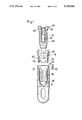
- FIG. 1is an exploded cross sectional view of an enossal single tooth implant according to the present invention, which is composed of a base body, a spacer ring and a base element;
- FIG. 2is an elevational view with portions broken away and in cross section of the assembled elements forming the single tooth implant
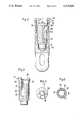
- FIG. 3is an elevational view with portions in cross section of the base element used in the assembly of FIG. 2;
- FIG. 4is a top plan view of the base element of FIG. 3;
- FIG. 5is a top plan view of the base body of FIGS. 1 and 2;
- FIG. 6is a bottom plan view of the ring element of FIGS. 1 and 2;
- FIG. 7is a elevational view with portions in cross section of the ring element utilized in the assembly of FIG. 2;
- FIG. 8is a top plan view of the ring element of FIG. 7.
- an implantgenerally indicated at 46 in FIG. 2, which is composed of a base body 10, a spacer assembly composed of a spacer bushing bottom or base element 12 and a spacer bushing top or ring member 14.
- the single tooth implant of the embodiment shown thereinhas a known base body 10, for example, such as disclosed in U.S. Pat. No. 5,026,280, which is made from a hydroxyapatite-coated titanium.
- the base body 10is provided with an internal bore 9 that has internal threads 16.
- the base body 10 adjacent an upper edge or end 19,has a recess 18, which is of a larger diameter than the bore 9 to provide a stop shoulder 20.
- the stop shoulder 20is provided with four uniformly, circumferentially spaced recess interlocking pockets 22 (illustrated in FIG. 5).
- the spacer bushing top or ring member 14at one end, is provided with a centering collar 24, whose external diameter corresponds to the annular recess 18 of the base body 10.
- the centering collarhas four uniformly, circumferentially spaced interlocking tongues 26 (see FIG. 6), which are complementary to the interlocking pockets 22 of the base body and coact therewith to form the means for preventing twisting between the ring member 14 and the base body 10.
- the ring member 14has an inner bore 25 with a large diameter counterbore 27, so as to provide an internal stop shoulder 28.
- the external surface of the spacer ring member 14has an external stop shoulder 40 and, above this, is provided with an enlarged portion which tapers outwardly and then tapers inwardly.
- the base element or spacer bushing bottom 12is provided with external threads 30 which correspond to the internal threads 16 of the base body 10.
- the spacer bushing bottom or base element 12is provided with an internal bore 31 having internal threads 32, which bore extends inward from a head portion 34 adjacent one end of the base element 12.
- the internal threads 32can receive the implant post, as described in the above-mentioned U.S. Pat. No. 5,026,280.
- the large diameter head portion 34forms an external shoulder 36, which is adjacent the upper end and which is complementary to the inner stop shoulder 28 of the ring member 14.
- the enlarged head 34is provided with attachment webs or projections 38, which enable attachment of a tool which will thread the element 12 into the base body 10.
- the spacer bushing top or ring member 14, as best illustrated in FIG. 7,has an external shoulder 40 which connects the centering collar 24 to the enlarged portion, which has a conical diverging middle portion and the conical converging upper portion 42.
- the upper portion 42is provided with a plurality of interlocking elements 44, which are circumferentially spaced therearound. As illustrated in FIGS. 7 and 8, four of these elements 44 are in the form of recesses, which form means for preventing twisting between a tooth structure which is fitted on the ring member 14. While the interlocking means are illustrated as being recesses, they could also be in the form of projections or protuberances.
- the above-described single tooth implantis assembled as follows: After the base body 10 is already held in the body tissue or jaw bone, the spacer bushing or ring member 14 is inserted thereon and, in conjuction with the interlocking pockets 22 and the interlocking tongues 26 bring about a twisting-restrained plug connection. The spacer bushing bottom or base element 12 is then threaded into the base body 10 with the shoulder 40 of the ring 14 being pressed against the distal circumferential edge 19 of the base body 10.
- the shoulder 36 of the element 12will engage the internal shoulder 28 of the ring member 14 to clamp or hold the ring member 14 on the base body 10 and, due to the coaction of the recesses 22 and the projections or tongues 26, axial twisting between the ring 14 and the base body 10 is prevented.
- the known implant post for the tooth replacement build-upis then threaded into the internal threads 32 of the spacer or base element 12. Since the base element 12 is only threaded into the base body 10, the implant post is not itself arranged in a twist-resistant manner relative to the base body 10.
- a twisting-resistant fixing of the tooth replacement structureis formed by the coaction with the recesses 44 of the spacer bushing or ring member 14. It should be noted that in the assembled position, such as illustrated in FIG. 2, the head 34 of the element 12 is received entirely within the counterbore 27 of the ring member 14.
Landscapes
- Health & Medical Sciences (AREA)
- Animal Behavior & Ethology (AREA)
- Dentistry (AREA)
- Epidemiology (AREA)
- Life Sciences & Earth Sciences (AREA)
- Oral & Maxillofacial Surgery (AREA)
- General Health & Medical Sciences (AREA)
- Public Health (AREA)
- Veterinary Medicine (AREA)
- Orthopedic Medicine & Surgery (AREA)
- Dental Prosthetics (AREA)
- Prostheses (AREA)
- Dental Preparations (AREA)
- Dental Tools And Instruments Or Auxiliary Dental Instruments (AREA)
Abstract
Description
The present invention is directed to an enossal single tooth implant, which is provided with a twisting restaint to enable a firm seating of a tooth replacement.
Enossal implants have been described in U.S. Pat. No. 4,793,808, whose disclosure is incorporated herein by reference thereto, and which claims priority from the same German Application as European PublishedApplication 0 216 031. The implants disclosed in this Patent have proven satisfactory. However, a difficulty may occur when the implant is used as a single tooth implant because it is not possible to reliably prevent the tooth replacement from twisting or turning relative to a base body, unless the individual parts of the implant and the tooth replacement are bonded together. If these two parts are bonded together, difficulties may occur in the case of a subsequent replacement for either the tooth replacement or the implant post, if either fails due to breakage.
U.S. Pat. No. 5,026,285, whose disclosure is incorporated herein by reference thereto, and which claims priority from German Application P 39 17 690 discloses an enossal individual tooth implant and locking tool for use with the implant. This implant includes a base body which is implanted in the jaw bone and has a threaded bore for receiving a threaded member or base element of a spacer ring, which has an upper ring element or spacer bushing top for spacing an implant post from the base body. The base element has a bore for receiving the post for mounting the tooth replacement. In order to obtain a twisting restraint, the spacer bushing top or ring element of the pre-assembled base single tooth implant, according to U.S. Pat. No. 5,026,285, is constructed in a ring nut-like manner and can be threaded onto the base element by means of an interlocking thread with a much smaller pitch than the set thread of the spacer bushing bottom or base element, which are received in the base body. The base body and the spacer formed by the bushing top and the spacer bushing bottom can be locked and braced with one another, which leads to a twisting restraint of both the spacer bushing bottom receiving the implant post and the spacer bushing top. However, it does have the disadvantage, in certain uses, in that, in the case of locking with a special tool, the spacer bushing top and bottom must be secured against any relative rotation or twisting. Problems are sometimes encountered in operating such a special tool, particularly when the operator is relatively inexperienced.
The present invention is directed to providing an improvement of the implant device disclosed in U.S. Pat. No. 5,026,285, which improvement enables a simpler means for providing a reliable twisting restraint.
To accomplish these goals, the present invention is directed to an improvement in an enossal single tooth implant, which has a base body with a threaded bore for receiving a threaded base element of a spacer, which threaded base element holds a spacing ring member on the base body. The improvements are that the base body has an annular recess for receiving a proximal centering collar of the spacer ring member, which recess is provided with at least one interlocking member and the spacer ring member is provided with at least one corresponding interlocking member to cooperate with the interlocking member of the base body. An inner bore of the ring member has a counterbore to provide an inner stop shoulder. The base element at one end has a head portion, whose external diameter corresponds to the internal diameter of the counterbore of the ring member and forms an external stop shoulder complementary to the inner stop shoulder of the ring member so that the base element will hold the ring member on the base body.
Following the threading of the base element into the base body, the head of the base element will not project out of the counterbore of the ring member.
According to the invention, it is optional to also provide that the base body interlocking member or members have at least one axial base body interlocking pocket in a stop shoulder of the annular recess and that the spacer ring member has at least one interlocking tongue for being received in the recess.
According to another embodiment of the invention, the base body and the ring member are provided, in each case, with four interlocking members arranged in a uniform circumferential spacing.
It is also possible, according to the invention, for the inner threads of the spacer bushing base element to extend only over a distal portion of the total longitudinal dimensions thereof.
The invention also proposes that the spacer ring member, on its upper end has interlocking elements for a twisting restraint build-up of the tooth replacement mounted thereon. The build-up interlocking elements can have surface depressions and/or protuberances on the front edge and on the surface of the spacer bushing ring.
The invention also, optionally, proposes that the area of the circumferential surface of the ring member provided with the interlocking elements is constructed so as to taper conically in the distal direction. In addition, the spacer ring member can be constructed on its distal end as a polygonal fastening head for the tooth replacement build-up.
The invention is based on the surprising finding that it is possible without using special screwing and locking tools that are required for the single tooth implant according to U.S. Pat. No. 5,026,285 to obtain a reliable tooth twisting restraint, in that between the spacer bushing ring member and the base body is provided an interlocking connection securing solely in the rotational direction and which is, in turn, axially secured by means of the screw-like base element. The base element and the implant post which will be screwed into it are not twist-restraining relative to the base body, unless an additional bonding or cementing is carried out. However, the spacer ring member is reliably twist-restrained as a result of the interlocking connections with the base body so that a tooth replacement can be built up thereon in a twisting-restrained manner. The enossal single tooth implant according to the present invention is particularly suitable for twist-restrained structures.
The single tooth implant according to the invention is, naturally, also usable as a normal implant, for example for fixing bridges or the like, if particular significance is attached to the means for twisting restraint.
Other advantages and features of the invention will be readily apparent from the following description of the preferred embodiments, the drawings and claims.
FIG. 1 is an exploded cross sectional view of an enossal single tooth implant according to the present invention, which is composed of a base body, a spacer ring and a base element;
FIG. 2 is an elevational view with portions broken away and in cross section of the assembled elements forming the single tooth implant;
FIG. 3 is an elevational view with portions in cross section of the base element used in the assembly of FIG. 2;
FIG. 4 is a top plan view of the base element of FIG. 3;
FIG. 5 is a top plan view of the base body of FIGS. 1 and 2;
FIG. 6 is a bottom plan view of the ring element of FIGS. 1 and 2;
FIG. 7 is a elevational view with portions in cross section of the ring element utilized in the assembly of FIG. 2; and
FIG. 8 is a top plan view of the ring element of FIG. 7.
The principles of the present invention are particularly useful in an implant, generally indicated at 46 in FIG. 2, which is composed of abase body 10, a spacer assembly composed of a spacer bushing bottom orbase element 12 and a spacer bushing top orring member 14.
As shown in FIGS. 1 and 2, the single tooth implant of the embodiment shown therein has a knownbase body 10, for example, such as disclosed in U.S. Pat. No. 5,026,280, which is made from a hydroxyapatite-coated titanium. Thebase body 10 is provided with aninternal bore 9 that hasinternal threads 16. Thebase body 10 adjacent an upper edge orend 19, has arecess 18, which is of a larger diameter than thebore 9 to provide astop shoulder 20. To provide means for preventing axial twisting, thestop shoulder 20 is provided with four uniformly, circumferentially spaced recess interlocking pockets 22 (illustrated in FIG. 5).
The spacer bushing top orring member 14, at one end, is provided with a centeringcollar 24, whose external diameter corresponds to theannular recess 18 of thebase body 10. The centering collar has four uniformly, circumferentially spaced interlocking tongues 26 (see FIG. 6), which are complementary to the interlockingpockets 22 of the base body and coact therewith to form the means for preventing twisting between thering member 14 and thebase body 10. Thering member 14 has aninner bore 25 with alarge diameter counterbore 27, so as to provide aninternal stop shoulder 28. The external surface of thespacer ring member 14 has anexternal stop shoulder 40 and, above this, is provided with an enlarged portion which tapers outwardly and then tapers inwardly.
The base element or spacer bushingbottom 12 is provided withexternal threads 30 which correspond to theinternal threads 16 of thebase body 10. The spacer bushing bottom orbase element 12 is provided with aninternal bore 31 havinginternal threads 32, which bore extends inward from ahead portion 34 adjacent one end of thebase element 12. Theinternal threads 32 can receive the implant post, as described in the above-mentioned U.S. Pat. No. 5,026,280. The largediameter head portion 34 forms anexternal shoulder 36, which is adjacent the upper end and which is complementary to theinner stop shoulder 28 of thering member 14.
As best illustrated in FIGS. 3 and 4, the enlargedhead 34 is provided with attachment webs orprojections 38, which enable attachment of a tool which will thread theelement 12 into thebase body 10.
The spacer bushing top orring member 14, as best illustrated in FIG. 7, has anexternal shoulder 40 which connects the centeringcollar 24 to the enlarged portion, which has a conical diverging middle portion and the conical convergingupper portion 42. Theupper portion 42 is provided with a plurality of interlockingelements 44, which are circumferentially spaced therearound. As illustrated in FIGS. 7 and 8, four of theseelements 44 are in the form of recesses, which form means for preventing twisting between a tooth structure which is fitted on thering member 14. While the interlocking means are illustrated as being recesses, they could also be in the form of projections or protuberances.
The above-described single tooth implant is assembled as follows: After thebase body 10 is already held in the body tissue or jaw bone, the spacer bushing orring member 14 is inserted thereon and, in conjuction with the interlocking pockets 22 and the interlockingtongues 26 bring about a twisting-restrained plug connection. The spacer bushing bottom orbase element 12 is then threaded into thebase body 10 with theshoulder 40 of thering 14 being pressed against the distalcircumferential edge 19 of thebase body 10. Theshoulder 36 of theelement 12 will engage theinternal shoulder 28 of thering member 14 to clamp or hold thering member 14 on thebase body 10 and, due to the coaction of therecesses 22 and the projections ortongues 26, axial twisting between thering 14 and thebase body 10 is prevented. The known implant post for the tooth replacement build-up is then threaded into theinternal threads 32 of the spacer orbase element 12. Since thebase element 12 is only threaded into thebase body 10, the implant post is not itself arranged in a twist-resistant manner relative to thebase body 10. A twisting-resistant fixing of the tooth replacement structure is formed by the coaction with therecesses 44 of the spacer bushing orring member 14. It should be noted that in the assembled position, such as illustrated in FIG. 2, thehead 34 of theelement 12 is received entirely within thecounterbore 27 of thering member 14.
Although various minor modifications may be suggested by those versed in the art, it should be understood that we wish to embody within the scope of the patent granted hereon all such modifications as reasonably and properly come within the scope of our contribution to the art.
Claims (9)
1. In an enossal single tooth implant including a base body threaded base element and a ring member, said base body having a threaded axial bore for receiving said threaded base element for holding the ring member on the base body, the improvements comprising means for preventing relative twisting of the ring member on the base body, said means including a base body having an axial recess adjacent one end, said recess including at least one interlocking member, the ring member having a centering collar having at least one interlocking member complementary to the interlocking member in said recess, said ring member having an inner bore with a counterbore to produce an inner stop shoulder, said base element, at one end, being provided with a head to form an external stop shoulder to engage the internal stop shoulder of the ring member to hold the ring member with the centering collar inserted in the recess of the base body with the coacting interlocking members engaged to prevent twisting therebetween.
2. In an enossal single tooth implant according to claim 1, wherein the axial length of the head portion of the base element and the axial length of the counterbore of the ring member are dimensioned so that the head portion of the base element is completely received within the counterbore of the ring member.
3. In an enossal single tooth implant according to claim 1, wherein the base body in the recess area has an internal stop shoulder and the interlocking member is an interlocking pocket in said stop shoulder and the interlocking member of the ring member is an interlocking tongue received in said interlocking pocket.
4. In an enossal single tooth implant according to claim 1, wherein the base body and the ring member are provided with four uniformly, circumferentially spaced interlocking members.
5. In an enossal single tooth implant according to claim 1, wherein the base element has an internal bore extending inward from said head portion provided with internal threads adjacent said head portion.
6. In an enossal single tooth implant according to claim 1, wherein the ring member is provided on an upper end opposite the centering collar with an interlocking element for forming means to prevent twisting between a tooth replacement and said ring member.
7. In an enossal single tooth implant according to claim 6, wherein the interlocking element of the ring member is a series of depressions and protuberances on said upper end of the ring member.
8. In an enossal single tooth implant according to claim 7, wherein the circumferential surface of the ring member provided with the interlocking elements tapers conically in the distal direction.
9. In an enossal single tooth implant according to claim 6, wherein the interlocking elements on the upper end of the ring member is formed by the ring member having a polygonal fastening head.
Applications Claiming Priority (2)
| Application Number | Priority Date | Filing Date | Title |
|---|---|---|---|
| DE4028855 | 1990-09-08 | ||
| DE4028855ADE4028855A1 (en) | 1989-05-31 | 1990-09-08 | Tooth implant protected against rotation - has post connected by screw union with base body, and distance socket with centering connection |
Publications (1)
| Publication Number | Publication Date |
|---|---|
| US5125840Atrue US5125840A (en) | 1992-06-30 |
Family
ID=6414059
Family Applications (1)
| Application Number | Title | Priority Date | Filing Date |
|---|---|---|---|
| US07/755,099Expired - Fee RelatedUS5125840A (en) | 1990-09-08 | 1991-09-05 | Enossal single tooth implant with twisting restraint |
Country Status (16)
| Country | Link |
|---|---|
| US (1) | US5125840A (en) |
| EP (1) | EP0475299B1 (en) |
| JP (1) | JP3001300B2 (en) |
| KR (1) | KR940005298B1 (en) |
| CN (1) | CN1032114C (en) |
| AT (1) | ATE117525T1 (en) |
| DE (1) | DE59104382D1 (en) |
| DK (1) | DK0475299T3 (en) |
| ES (1) | ES2068447T3 (en) |
| GR (1) | GR3015833T3 (en) |
| HK (1) | HK66795A (en) |
| HU (1) | HU214166B (en) |
| IL (1) | IL99411A (en) |
| RU (1) | RU2072812C1 (en) |
| TW (1) | TW257668B (en) |
| YU (1) | YU47926B (en) |
Cited By (69)
| Publication number | Priority date | Publication date | Assignee | Title |
|---|---|---|---|---|
| US5368483A (en)* | 1993-06-14 | 1994-11-29 | Institut Straumann Ag | Device-for fixing a dental prosthesis to a jaw bone |
| US5427906A (en)* | 1993-05-27 | 1995-06-27 | Hansen; Gorm P. | System for bracing dental implants or natural tooth roots to secure artificial teeth |
| WO1995017136A1 (en)* | 1993-12-21 | 1995-06-29 | Calcitek, Inc. | Dental implant assembly having tactile feedback |
| US5547324A (en)* | 1991-04-20 | 1996-08-20 | Eberle Medizintechnische Elemente Gmbh | Member provided with an external screw thread |
| US5549475A (en)* | 1993-12-09 | 1996-08-27 | Eberle Medizintechnische Elements Gmbh | Enossal single-tooth implant |
| US5582299A (en)* | 1994-03-01 | 1996-12-10 | Implant Innovations, Inc. | Dental implant packaging |
| US5704788A (en)* | 1997-02-12 | 1998-01-06 | Milne; Robert H. | Dental implant abutment screw lock |
| US5810590A (en)* | 1995-01-30 | 1998-09-22 | Fried; Paula S. | Dental implants and methods for extending service life |
| US5823776A (en)* | 1995-09-20 | 1998-10-20 | Imz Fertigungs- Und Vertiebsgellschaft Fur Dentale Technologie Mbh | Enossal single tooth implant with twisting prevention |
| US5888218A (en)* | 1997-03-27 | 1999-03-30 | Folsom Metal Products | Implant micro seal |
| US5908298A (en)* | 1995-03-17 | 1999-06-01 | Duerr; Walter | Enossal single tooth implant with spacer sleeve |
| US5915968A (en)* | 1995-09-06 | 1999-06-29 | Imz Fertigungs-Und Vertriebsgesellschaft Fur Dentale Technologie Mbh | Enossal single tooth implant |
| US5951287A (en)* | 1997-04-17 | 1999-09-14 | Hawkinson; Roy T. | Dental implant failed fastener recovery systems, devices and methods |
| US5961330A (en)* | 1998-04-09 | 1999-10-05 | Sulzer Calcitek Inc. | Vial for dental implant delivery system |
| US5964591A (en)* | 1997-04-09 | 1999-10-12 | Implant Innovations, Inc. | Implant delivery system |
| US5989028A (en)* | 1997-05-15 | 1999-11-23 | Core-Vent Corporation | Non-submergible, one-part, root-form endosseous dental implants |
| US6076660A (en)* | 1998-02-05 | 2000-06-20 | Sulzer Calcitek Inc. | Vial for dental implant delivery system |
| US6086371A (en)* | 1998-02-05 | 2000-07-11 | Sulzer Orthopedics Inc. | Dental implant delivery system having driver mount with removable flange |
| US6116904A (en)* | 1996-08-21 | 2000-09-12 | Imz Fertigungs- Und Vertriebsgesellschaft Fur Dentale Technologie Mbh | Endosteal single tooth implant secured against torsion, stamping tool and positioning aid for producing such a single tooth implant |
| US6168436B1 (en)* | 1997-06-18 | 2001-01-02 | O'brien Gary | Universal dental implant abutment system |
| US6203323B1 (en) | 1998-04-08 | 2001-03-20 | Implant Innovations, Inc. | Implant delivery system |
| USD441448S1 (en) | 2000-05-08 | 2001-05-01 | Nobel Biocare Usa, Inc | Snap-in impression coping |
| US6227859B1 (en)* | 1997-05-24 | 2001-05-08 | Franz Sutter | Dental implant and device with a dental implant |
| US6247933B1 (en) | 1999-12-10 | 2001-06-19 | Sulzer Dental Inc. | Dental implant delivery system |
| US6350126B1 (en)* | 2000-09-01 | 2002-02-26 | Ricardo Levisman | Bone implant |
| US6382977B1 (en) | 2000-03-02 | 2002-05-07 | Nobel Biocare Usa, Inc. | Snap-in impression coping |
| US6416324B1 (en) | 1999-12-10 | 2002-07-09 | Sulzer Dental Inc. | One step dental implant delivery system |
| US20030054318A1 (en)* | 2001-09-17 | 2003-03-20 | Christopher Gervais | Torque limiting implant drive system |
| US20030054319A1 (en)* | 2001-09-17 | 2003-03-20 | Christopher Gervais | Impression post and temporary abutment and method of making dental restoration |
| US6619958B2 (en) | 1997-04-09 | 2003-09-16 | Implant Innovations, Inc. | Implant delivery system |
| US6666685B2 (en)* | 2001-02-19 | 2003-12-23 | Plauto Pires De Almeida Filho | Disposition introduced in an assembly of elements used in osteo-integrated implants |
| US20040038179A1 (en)* | 2001-12-07 | 2004-02-26 | Ajay Kumar | Healing abutment |
| US6726480B1 (en) | 1997-05-24 | 2004-04-27 | Straumann Holding Ag | Support for sustaining and/or forming a dental prosthesis |
| US20040241610A1 (en)* | 2003-01-03 | 2004-12-02 | Steve Hurson | Dental implant system |
| US20050008990A1 (en)* | 2003-02-26 | 2005-01-13 | Therics, Inc. | Method and system for repairing endosseous implants, such as with a bone graft implant |
| US6942667B1 (en)* | 2002-04-02 | 2005-09-13 | Vanderbilt University | Bone anchor |
| USRE38945E1 (en) | 1995-01-30 | 2006-01-24 | Paula S. Fried | Dental implants and methods for extending service life |
| US20060127849A1 (en)* | 2004-12-15 | 2006-06-15 | Ricardo Levisman | Dental implant system |
| KR100597389B1 (en) | 2004-08-17 | 2006-07-10 | 이달호 | Fixtures for dental implants, dental implants, impression coping and lab analog |
| KR100597392B1 (en) | 2004-08-20 | 2006-07-10 | 이달호 | Dental Implants, Impression Copings and Lab Analogs |
| EP1704829A1 (en) | 2005-03-21 | 2006-09-27 | Friadent GmbH | Abutment set for a dental implant |
| US20060246397A1 (en)* | 2003-11-05 | 2006-11-02 | Friadent Gmbh | Multi part non metal implant |
| US20060246396A1 (en)* | 2005-04-27 | 2006-11-02 | Implant Innovations, Inc. | Pre-stressed implant component and assembly |
| US20080008981A1 (en)* | 2005-03-21 | 2008-01-10 | Friadent Gmbh | Abutment set for a dental implant |
| US7338286B2 (en) | 2002-11-13 | 2008-03-04 | Biomet 3I, Inc. | Dental implant system |
| US20080066766A1 (en)* | 2002-09-06 | 2008-03-20 | Apneon, Inc. | Implantable devices, systems, and methods for maintaining desired orientations in targeted tissue regions |
| US20080257760A1 (en)* | 2007-04-23 | 2008-10-23 | Gc Corporation | Container for fixture |
| US20090111072A1 (en)* | 2007-10-30 | 2009-04-30 | Alan Lombardo | Dental implant and abutment mating system |
| US20090157124A1 (en)* | 2007-12-13 | 2009-06-18 | Smith & Nephew, Inc. | Anchoring System |
| US20110076644A1 (en)* | 2008-04-18 | 2011-03-31 | Neoss Limited | Locking Ring |
| US20110097687A1 (en)* | 2008-04-18 | 2011-04-28 | Neoss Limited | Spacer Element |
| USRE43470E1 (en) | 1995-11-17 | 2012-06-12 | Nobel Biocare Services, Ag | Dental implant systems and methods |
| US20150147721A1 (en)* | 2012-05-09 | 2015-05-28 | Dentisel, S.L. | Dental prosthesis system |
| USD731655S1 (en) | 2013-03-15 | 2015-06-09 | Benedict Lui | Dental implant abutment |
| USD732169S1 (en) | 2013-09-16 | 2015-06-16 | Benedict Lui | Dental implant abutment |
| US20160367341A1 (en)* | 2014-03-11 | 2016-12-22 | Implant Protesis Dental 2004 S.L. | Dental implant prosthetic structure |
| US9925024B2 (en) | 2011-06-28 | 2018-03-27 | Biomet 3I, Llc | Dental implant and abutment tools |
| US20180140387A1 (en)* | 2015-05-06 | 2018-05-24 | Anthogyr | Connection device between a dental prosthesis and a master model |
| WO2018220612A1 (en)* | 2017-05-29 | 2018-12-06 | MIS Implants Technologies Ltd. | Dental connection system |
| US10188378B2 (en) | 2013-03-06 | 2019-01-29 | Smith & Nephew, Inc. | Microanchor |
| USD840038S1 (en) | 2017-09-05 | 2019-02-05 | MIS Implants Technologies Ltd. | Dental connector |
| USD840039S1 (en) | 2017-09-05 | 2019-02-05 | MIS Implants Technologies Ltd. | Dental connector |
| USD840037S1 (en) | 2017-09-05 | 2019-02-05 | MIS Implants Technologies Ltd. | Dental connector |
| US20190133720A1 (en)* | 2017-11-03 | 2019-05-09 | Kwang Seob Kim | Tooth implant system |
| US10507082B2 (en)* | 2017-02-28 | 2019-12-17 | Elsner Global Llc | Impression jig assembly |
| US10531937B2 (en)* | 2016-10-25 | 2020-01-14 | Chi Keung Lee | Dental implant system with positive abutment screw locking and retrieval mechanism |
| US10610334B2 (en) | 2015-11-26 | 2020-04-07 | MIS Implants Technologies Ltd. | Abutment, coping and method of connecting thereof in a dental multi-unit system |
| US20200138552A1 (en)* | 2012-07-09 | 2020-05-07 | Nobel Biocare Services Ag | Abutment system and dental methods |
| CN115802982A (en)* | 2020-09-22 | 2023-03-14 | 金正焕 | Implant assembly |
Families Citing this family (13)
| Publication number | Priority date | Publication date | Assignee | Title |
|---|---|---|---|---|
| IT222859Z2 (en)* | 1991-08-01 | 1995-05-08 | Bartolomeo Assenza | OSTEOINTEGRATED COMPLEX CONSTITUTED BY A PIN AND AN INTERCHANGEABLE COLLAR HAVING THE HEIGHT CHOSEN ON THE BASIS OF THE THICKNESS OF THE PATIENT'S EPITELIAL CONNECTIVAL MUCOUS LAYER |
| DE4224785C2 (en)* | 1992-07-27 | 1997-04-30 | Imz Fertigung Vertrieb | Endosseous dental implant for a fixed denture and insertion tool |
| JP3032941B2 (en)* | 1994-12-28 | 2000-04-17 | 恒久 下田 | Dental implant |
| FR2733144B1 (en)* | 1995-04-18 | 1997-08-08 | Laurent Isnard | IMPLANT FOR DENTAL PROSTHESIS |
| FR2745998B1 (en)* | 1996-03-13 | 1998-06-12 | DENTAL PROSTHESIS HOLDER WITH ANTI-ROTATION MECHANISM | |
| US6430207B1 (en) | 1998-09-23 | 2002-08-06 | Sarnoff Corporation | High-power laser with transverse mode filter |
| FR2828090B1 (en)* | 2001-08-03 | 2003-11-21 | Andre Benhamou | IMPLANT FOR DENTAL OR SIMILAR USE, CONSISTING OF A CORE AND A CERAMIC SLEEVE CONNECTED TO ONE ANOTHER BY GLUE |
| JP4178240B2 (en) | 2003-10-28 | 2008-11-12 | 富士通マイクロエレクトロニクス株式会社 | Manufacturing method of semiconductor device |
| ES2307352B1 (en) | 2005-04-12 | 2009-09-18 | Bti, I+D, S.L. | DENTAL IMPLANT AND PARTS INTENDED TO BE CONNECTED TO A DENTAL IMPLANT, AND THE INTERNAL CONNECTION BETWEEN THE DENTAL IMPLANT AND EACH PIECE. |
| DK2119414T3 (en) | 2005-06-03 | 2013-05-27 | Straumann Holding Ag | Connection to multiple implant dental implant system |
| DE202005022133U1 (en) | 2005-06-03 | 2015-02-24 | Straumann Holding Ag | Coupling for multi-part dental implant system |
| CN104352284B (en)* | 2014-10-09 | 2018-06-05 | 儒伽医疗有限公司 | A kind of dental prosthetic method |
| CN119326956B (en)* | 2024-12-19 | 2025-03-25 | 吉林大学 | Preparation of multi-layered zinc-hydrogel heterostructures as medical implants |
Citations (11)
| Publication number | Priority date | Publication date | Assignee | Title |
|---|---|---|---|---|
| US4746293A (en)* | 1985-09-16 | 1988-05-24 | Dan Lundgren | Connecting devices |
| US4756689A (en)* | 1985-09-16 | 1988-07-12 | Dan Lundgren | Connecting devices |
| US4790753A (en)* | 1987-02-13 | 1988-12-13 | Fradera Alejandro P | Screw for dental implants |
| US4793808A (en)* | 1985-09-03 | 1988-12-27 | Axel Kirsch | Enossal implant |
| US4850870A (en)* | 1987-10-23 | 1989-07-25 | Implant Innovations, Inc. | Prosthodontic restoration components |
| US4872839A (en)* | 1987-06-12 | 1989-10-10 | Nobelpharma Ab | Spacer for dental implants |
| US4955811A (en)* | 1988-06-23 | 1990-09-11 | Implant Innovations, Inc. | Non-rotational single-tooth prosthodontic restoration |
| US5026285A (en)* | 1989-05-31 | 1991-06-25 | Axel Kirsch | Enossal individual tooth implant and locking tool for use with such an implant |
| US5026280A (en)* | 1988-11-24 | 1991-06-25 | Imz Fertigungs Und Vertriebsgellschaft Fur Dentale Technologie Mbh | Enossal implant with an elastic intermediate element and a metal spacer element |
| US5040982A (en)* | 1990-06-28 | 1991-08-20 | Stefan Dogar Sorin | Dental implant and conversion assembly |
| US5052931A (en)* | 1988-12-10 | 1991-10-01 | Imz Fertigungs-Und Vertriebsgesellschaft Fur Dentale Technologie Mbh | Enossal implant |
Family Cites Families (1)
| Publication number | Priority date | Publication date | Assignee | Title |
|---|---|---|---|---|
| SE8902064D0 (en)* | 1989-06-07 | 1989-06-07 | Erik Thelberg | REMOVABLE SAVING BODY |
- 1991
- 1991-09-05JPJP3225969Apatent/JP3001300B2/ennot_activeExpired - Fee Related
- 1991-09-05USUS07/755,099patent/US5125840A/ennot_activeExpired - Fee Related
- 1991-09-05ILIL9941191Apatent/IL99411A/ennot_activeIP Right Cessation
- 1991-09-06HUHU912888Apatent/HU214166B/ennot_activeIP Right Cessation
- 1991-09-06DEDE59104382Tpatent/DE59104382D1/ennot_activeExpired - Fee Related
- 1991-09-06EPEP91115109Apatent/EP0475299B1/ennot_activeExpired - Lifetime
- 1991-09-06RUSU915001706Apatent/RU2072812C1/enactive
- 1991-09-06YUYU149491Apatent/YU47926B/enunknown
- 1991-09-06ESES91115109Tpatent/ES2068447T3/ennot_activeExpired - Lifetime
- 1991-09-06ATAT91115109Tpatent/ATE117525T1/ennot_activeIP Right Cessation
- 1991-09-06DKDK91115109.0Tpatent/DK0475299T3/enactive
- 1991-09-07CNCN91109577Apatent/CN1032114C/ennot_activeExpired - Fee Related
- 1991-09-09KRKR1019910015697Apatent/KR940005298B1/ennot_activeExpired - Fee Related
- 1991-09-12TWTW080107212Apatent/TW257668B/zhactive
- 1995
- 1995-04-17GRGR950400963Tpatent/GR3015833T3/enunknown
- 1995-05-04HKHK66795Apatent/HK66795A/ennot_activeIP Right Cessation
Patent Citations (12)
| Publication number | Priority date | Publication date | Assignee | Title |
|---|---|---|---|---|
| US4793808A (en)* | 1985-09-03 | 1988-12-27 | Axel Kirsch | Enossal implant |
| US4746293A (en)* | 1985-09-16 | 1988-05-24 | Dan Lundgren | Connecting devices |
| US4756689A (en)* | 1985-09-16 | 1988-07-12 | Dan Lundgren | Connecting devices |
| US4790753A (en)* | 1987-02-13 | 1988-12-13 | Fradera Alejandro P | Screw for dental implants |
| US4872839A (en)* | 1987-06-12 | 1989-10-10 | Nobelpharma Ab | Spacer for dental implants |
| US4850870A (en)* | 1987-10-23 | 1989-07-25 | Implant Innovations, Inc. | Prosthodontic restoration components |
| US4850870C1 (en)* | 1987-10-23 | 2001-07-24 | Implant Innovations Inc | Prosthodontic restoration components |
| US4955811A (en)* | 1988-06-23 | 1990-09-11 | Implant Innovations, Inc. | Non-rotational single-tooth prosthodontic restoration |
| US5026280A (en)* | 1988-11-24 | 1991-06-25 | Imz Fertigungs Und Vertriebsgellschaft Fur Dentale Technologie Mbh | Enossal implant with an elastic intermediate element and a metal spacer element |
| US5052931A (en)* | 1988-12-10 | 1991-10-01 | Imz Fertigungs-Und Vertriebsgesellschaft Fur Dentale Technologie Mbh | Enossal implant |
| US5026285A (en)* | 1989-05-31 | 1991-06-25 | Axel Kirsch | Enossal individual tooth implant and locking tool for use with such an implant |
| US5040982A (en)* | 1990-06-28 | 1991-08-20 | Stefan Dogar Sorin | Dental implant and conversion assembly |
Cited By (99)
| Publication number | Priority date | Publication date | Assignee | Title |
|---|---|---|---|---|
| US5547324A (en)* | 1991-04-20 | 1996-08-20 | Eberle Medizintechnische Elemente Gmbh | Member provided with an external screw thread |
| US5427906A (en)* | 1993-05-27 | 1995-06-27 | Hansen; Gorm P. | System for bracing dental implants or natural tooth roots to secure artificial teeth |
| US5567155A (en)* | 1993-05-27 | 1996-10-22 | Hansen; Gorm P. | System for bracing dental implants or natural tooth roots to secure artificial teeth |
| US5368483A (en)* | 1993-06-14 | 1994-11-29 | Institut Straumann Ag | Device-for fixing a dental prosthesis to a jaw bone |
| US5549475A (en)* | 1993-12-09 | 1996-08-27 | Eberle Medizintechnische Elements Gmbh | Enossal single-tooth implant |
| WO1995017136A1 (en)* | 1993-12-21 | 1995-06-29 | Calcitek, Inc. | Dental implant assembly having tactile feedback |
| US5449291A (en)* | 1993-12-21 | 1995-09-12 | Calcitek, Inc. | Dental implant assembly having tactile feedback |
| US5582299A (en)* | 1994-03-01 | 1996-12-10 | Implant Innovations, Inc. | Dental implant packaging |
| USRE38945E1 (en) | 1995-01-30 | 2006-01-24 | Paula S. Fried | Dental implants and methods for extending service life |
| US5810590A (en)* | 1995-01-30 | 1998-09-22 | Fried; Paula S. | Dental implants and methods for extending service life |
| US5908298A (en)* | 1995-03-17 | 1999-06-01 | Duerr; Walter | Enossal single tooth implant with spacer sleeve |
| US5915968A (en)* | 1995-09-06 | 1999-06-29 | Imz Fertigungs-Und Vertriebsgesellschaft Fur Dentale Technologie Mbh | Enossal single tooth implant |
| US5823776A (en)* | 1995-09-20 | 1998-10-20 | Imz Fertigungs- Und Vertiebsgellschaft Fur Dentale Technologie Mbh | Enossal single tooth implant with twisting prevention |
| USRE43470E1 (en) | 1995-11-17 | 2012-06-12 | Nobel Biocare Services, Ag | Dental implant systems and methods |
| US6116904A (en)* | 1996-08-21 | 2000-09-12 | Imz Fertigungs- Und Vertriebsgesellschaft Fur Dentale Technologie Mbh | Endosteal single tooth implant secured against torsion, stamping tool and positioning aid for producing such a single tooth implant |
| US5704788A (en)* | 1997-02-12 | 1998-01-06 | Milne; Robert H. | Dental implant abutment screw lock |
| US5888218A (en)* | 1997-03-27 | 1999-03-30 | Folsom Metal Products | Implant micro seal |
| US5964591A (en)* | 1997-04-09 | 1999-10-12 | Implant Innovations, Inc. | Implant delivery system |
| US20050191600A1 (en)* | 1997-04-09 | 2005-09-01 | Beaty Keith D. | Implant delivery system |
| US7344376B2 (en) | 1997-04-09 | 2008-03-18 | Biomet 3I, Inc. | Implant delivery system |
| US6619958B2 (en) | 1997-04-09 | 2003-09-16 | Implant Innovations, Inc. | Implant delivery system |
| US8087935B2 (en) | 1997-04-09 | 2012-01-03 | Biomet 3I, Llc | Implant delivery system |
| US5951287A (en)* | 1997-04-17 | 1999-09-14 | Hawkinson; Roy T. | Dental implant failed fastener recovery systems, devices and methods |
| US5989028A (en)* | 1997-05-15 | 1999-11-23 | Core-Vent Corporation | Non-submergible, one-part, root-form endosseous dental implants |
| US6726480B1 (en) | 1997-05-24 | 2004-04-27 | Straumann Holding Ag | Support for sustaining and/or forming a dental prosthesis |
| US6227859B1 (en)* | 1997-05-24 | 2001-05-08 | Franz Sutter | Dental implant and device with a dental implant |
| US6168436B1 (en)* | 1997-06-18 | 2001-01-02 | O'brien Gary | Universal dental implant abutment system |
| US6076660A (en)* | 1998-02-05 | 2000-06-20 | Sulzer Calcitek Inc. | Vial for dental implant delivery system |
| US6086371A (en)* | 1998-02-05 | 2000-07-11 | Sulzer Orthopedics Inc. | Dental implant delivery system having driver mount with removable flange |
| US6203323B1 (en) | 1998-04-08 | 2001-03-20 | Implant Innovations, Inc. | Implant delivery system |
| US5961330A (en)* | 1998-04-09 | 1999-10-05 | Sulzer Calcitek Inc. | Vial for dental implant delivery system |
| US6416324B1 (en) | 1999-12-10 | 2002-07-09 | Sulzer Dental Inc. | One step dental implant delivery system |
| US6247933B1 (en) | 1999-12-10 | 2001-06-19 | Sulzer Dental Inc. | Dental implant delivery system |
| US6382977B1 (en) | 2000-03-02 | 2002-05-07 | Nobel Biocare Usa, Inc. | Snap-in impression coping |
| USD441448S1 (en) | 2000-05-08 | 2001-05-01 | Nobel Biocare Usa, Inc | Snap-in impression coping |
| US6350126B1 (en)* | 2000-09-01 | 2002-02-26 | Ricardo Levisman | Bone implant |
| US6666685B2 (en)* | 2001-02-19 | 2003-12-23 | Plauto Pires De Almeida Filho | Disposition introduced in an assembly of elements used in osteo-integrated implants |
| US7160109B2 (en) | 2001-09-17 | 2007-01-09 | Sulzer Dental Inc. | Torque limiting implant drive system |
| US20030054318A1 (en)* | 2001-09-17 | 2003-03-20 | Christopher Gervais | Torque limiting implant drive system |
| US7137816B2 (en) | 2001-09-17 | 2006-11-21 | Zimmer Dental Inc. | Impression post and temporary abutment and method of making dental restoration |
| US20030054319A1 (en)* | 2001-09-17 | 2003-03-20 | Christopher Gervais | Impression post and temporary abutment and method of making dental restoration |
| US20040038179A1 (en)* | 2001-12-07 | 2004-02-26 | Ajay Kumar | Healing abutment |
| US6942667B1 (en)* | 2002-04-02 | 2005-09-13 | Vanderbilt University | Bone anchor |
| US20080066766A1 (en)* | 2002-09-06 | 2008-03-20 | Apneon, Inc. | Implantable devices, systems, and methods for maintaining desired orientations in targeted tissue regions |
| US8707959B2 (en)* | 2002-09-06 | 2014-04-29 | Koninklijke Philips N.V. | Implantable devices, systems, and methods for maintaining desired orientations in targeted tissue regions |
| US9549793B2 (en) | 2002-11-13 | 2017-01-24 | Biomet 3I, Llc | Dental implant system |
| US8636511B2 (en) | 2002-11-13 | 2014-01-28 | Biomet 3I, Llc | Dental implant system |
| US9883927B2 (en) | 2002-11-13 | 2018-02-06 | Biomet 3I, Llc | Dental implant system |
| US7484959B2 (en) | 2002-11-13 | 2009-02-03 | Biomet 3I, Llc | Dental implant system |
| US9931182B2 (en) | 2002-11-13 | 2018-04-03 | Biomet 3I, Llc | Dental implant system |
| US7338286B2 (en) | 2002-11-13 | 2008-03-04 | Biomet 3I, Inc. | Dental implant system |
| US20040241610A1 (en)* | 2003-01-03 | 2004-12-02 | Steve Hurson | Dental implant system |
| US20060204928A1 (en)* | 2003-01-03 | 2006-09-14 | Steve Hurson | Dental implant system |
| US20050008990A1 (en)* | 2003-02-26 | 2005-01-13 | Therics, Inc. | Method and system for repairing endosseous implants, such as with a bone graft implant |
| US20060246397A1 (en)* | 2003-11-05 | 2006-11-02 | Friadent Gmbh | Multi part non metal implant |
| KR100597389B1 (en) | 2004-08-17 | 2006-07-10 | 이달호 | Fixtures for dental implants, dental implants, impression coping and lab analog |
| KR100597392B1 (en) | 2004-08-20 | 2006-07-10 | 이달호 | Dental Implants, Impression Copings and Lab Analogs |
| US20060127849A1 (en)* | 2004-12-15 | 2006-06-15 | Ricardo Levisman | Dental implant system |
| EP1704829A1 (en) | 2005-03-21 | 2006-09-27 | Friadent GmbH | Abutment set for a dental implant |
| US20080008981A1 (en)* | 2005-03-21 | 2008-01-10 | Friadent Gmbh | Abutment set for a dental implant |
| US20060246396A1 (en)* | 2005-04-27 | 2006-11-02 | Implant Innovations, Inc. | Pre-stressed implant component and assembly |
| US7850452B2 (en)* | 2005-04-27 | 2010-12-14 | Biomet 3I, Llc | Pre-stressed implant component and assembly |
| US20080257760A1 (en)* | 2007-04-23 | 2008-10-23 | Gc Corporation | Container for fixture |
| US20090111072A1 (en)* | 2007-10-30 | 2009-04-30 | Alan Lombardo | Dental implant and abutment mating system |
| US9370357B2 (en) | 2007-12-13 | 2016-06-21 | Smith & Nephew, Inc. | Anchoring system |
| US8454654B2 (en)* | 2007-12-13 | 2013-06-04 | Smith & Nephew, Inc. | Anchoring system |
| US20130238026A1 (en)* | 2007-12-13 | 2013-09-12 | Smith & Nephew, Inc. | Anchoring system |
| US8672970B2 (en)* | 2007-12-13 | 2014-03-18 | Smith & Nephew, Inc. | Anchoring system |
| US20090157124A1 (en)* | 2007-12-13 | 2009-06-18 | Smith & Nephew, Inc. | Anchoring System |
| US20110076644A1 (en)* | 2008-04-18 | 2011-03-31 | Neoss Limited | Locking Ring |
| US9522051B2 (en) | 2008-04-18 | 2016-12-20 | Neoss Limited | Spacer element |
| US20110097687A1 (en)* | 2008-04-18 | 2011-04-28 | Neoss Limited | Spacer Element |
| US10952826B2 (en) | 2011-06-28 | 2021-03-23 | Biomet 3I, Llc | System and method of dental implant and interface to abutment for restoration |
| US9925024B2 (en) | 2011-06-28 | 2018-03-27 | Biomet 3I, Llc | Dental implant and abutment tools |
| US20150147721A1 (en)* | 2012-05-09 | 2015-05-28 | Dentisel, S.L. | Dental prosthesis system |
| US10507084B2 (en)* | 2012-05-09 | 2019-12-17 | Clinica Dental Costa Codina, S.L. | Dental prosthesis system |
| US12390309B2 (en)* | 2012-07-09 | 2025-08-19 | Nobel Biocare Services Ag | Abutment system and dental methods |
| US20200138552A1 (en)* | 2012-07-09 | 2020-05-07 | Nobel Biocare Services Ag | Abutment system and dental methods |
| US10188378B2 (en) | 2013-03-06 | 2019-01-29 | Smith & Nephew, Inc. | Microanchor |
| USD731655S1 (en) | 2013-03-15 | 2015-06-09 | Benedict Lui | Dental implant abutment |
| USD751709S1 (en) | 2013-03-15 | 2016-03-15 | Benedict Lui | Dental implant abutment |
| USD732169S1 (en) | 2013-09-16 | 2015-06-16 | Benedict Lui | Dental implant abutment |
| US20160367341A1 (en)* | 2014-03-11 | 2016-12-22 | Implant Protesis Dental 2004 S.L. | Dental implant prosthetic structure |
| US20180140387A1 (en)* | 2015-05-06 | 2018-05-24 | Anthogyr | Connection device between a dental prosthesis and a master model |
| US10610334B2 (en) | 2015-11-26 | 2020-04-07 | MIS Implants Technologies Ltd. | Abutment, coping and method of connecting thereof in a dental multi-unit system |
| US10531937B2 (en)* | 2016-10-25 | 2020-01-14 | Chi Keung Lee | Dental implant system with positive abutment screw locking and retrieval mechanism |
| US10507082B2 (en)* | 2017-02-28 | 2019-12-17 | Elsner Global Llc | Impression jig assembly |
| WO2018220612A1 (en)* | 2017-05-29 | 2018-12-06 | MIS Implants Technologies Ltd. | Dental connection system |
| KR20200012951A (en)* | 2017-05-29 | 2020-02-05 | 엠아이에스 임플란츠 테크놀러지스 리미티드 | Tooth connection system |
| CN110944598A (en)* | 2017-05-29 | 2020-03-31 | 米斯移植技术公司 | Dental connection system |
| CN110944598B (en)* | 2017-05-29 | 2023-03-24 | 米斯移植技术公司 | Dental connection system |
| US10813723B2 (en) | 2017-05-29 | 2020-10-27 | MIS Implants Technologies Ltd. | Dental connection system |
| RU2757708C2 (en)* | 2017-05-29 | 2021-10-20 | ЭмАйЭс ИМПЛАНТС ТЕКНОЛОДЖИС ЛТД. | Dental connective system |
| USD840037S1 (en) | 2017-09-05 | 2019-02-05 | MIS Implants Technologies Ltd. | Dental connector |
| USD840039S1 (en) | 2017-09-05 | 2019-02-05 | MIS Implants Technologies Ltd. | Dental connector |
| USD840038S1 (en) | 2017-09-05 | 2019-02-05 | MIS Implants Technologies Ltd. | Dental connector |
| US20190133720A1 (en)* | 2017-11-03 | 2019-05-09 | Kwang Seob Kim | Tooth implant system |
| US10772710B2 (en)* | 2017-11-03 | 2020-09-15 | Kwang Seob Kim | Tooth implant system |
| CN115802982A (en)* | 2020-09-22 | 2023-03-14 | 金正焕 | Implant assembly |
Also Published As
| Publication number | Publication date |
|---|---|
| GR3015833T3 (en) | 1995-07-31 |
| HUT58983A (en) | 1992-04-28 |
| CN1062834A (en) | 1992-07-22 |
| IL99411A (en) | 1996-01-19 |
| HU912888D0 (en) | 1992-01-28 |
| TW257668B (en) | 1995-09-21 |
| CN1032114C (en) | 1996-06-26 |
| KR920005955A (en) | 1992-04-27 |
| JPH05145A (en) | 1993-01-08 |
| YU149491A (en) | 1994-06-24 |
| KR940005298B1 (en) | 1994-06-16 |
| HK66795A (en) | 1995-05-12 |
| ATE117525T1 (en) | 1995-02-15 |
| HU214166B (en) | 1998-01-28 |
| YU47926B (en) | 1996-05-20 |
| JP3001300B2 (en) | 2000-01-24 |
| RU2072812C1 (en) | 1997-02-10 |
| DK0475299T3 (en) | 1995-06-26 |
| EP0475299A1 (en) | 1992-03-18 |
| IL99411A0 (en) | 1992-08-18 |
| DE59104382D1 (en) | 1995-03-09 |
| EP0475299B1 (en) | 1995-01-25 |
| ES2068447T3 (en) | 1995-04-16 |
Similar Documents
| Publication | Publication Date | Title |
|---|---|---|
| US5125840A (en) | Enossal single tooth implant with twisting restraint | |
| US5026285A (en) | Enossal individual tooth implant and locking tool for use with such an implant | |
| EP2119414B1 (en) | Coupling for a multi-part dental implant system | |
| EP0126624B1 (en) | Fixed dental implant | |
| AU656904B2 (en) | A device for tooth implantation comprising a locking screw | |
| US5662474A (en) | Spacing member for tooth implant | |
| US4995810A (en) | Tool for a prosthetic part | |
| US5782918A (en) | Implant abutment system | |
| US6648643B2 (en) | Dental implant/abutment interface and system having prong and channel interconnections | |
| US5104318A (en) | Implant assembly for anchoring an artificial tooth | |
| US5449291A (en) | Dental implant assembly having tactile feedback | |
| US6007337A (en) | Jaw implant | |
| US20030162149A1 (en) | Arrangement comprising a spacer element for an implant, such a spacer element and a screwdriver for fastening the spacer element | |
| US5908298A (en) | Enossal single tooth implant with spacer sleeve | |
| JPH0856971A (en) | Member to be buried in organism,which is inserted between corpus vertebrae of spine as space-retaining member | |
| CA2257970C (en) | Fixture, prosthesis anchoring device and prosthesis | |
| US20060127849A1 (en) | Dental implant system | |
| JPH0728877B2 (en) | Denture implant | |
| US20080057477A1 (en) | Dental implant screw system | |
| SE502561C2 (en) | Spacer means for an attachment element permanently anchored in the jaw bone | |
| US5547324A (en) | Member provided with an external screw thread | |
| KR102208556B1 (en) | Dental implant assembly and dental abutment | |
| EP0893105B1 (en) | Dental implant | |
| US20030194680A1 (en) | Dental implant fixture | |
| EP0687450B1 (en) | Dental implant |
Legal Events
| Date | Code | Title | Description |
|---|---|---|---|
| AS | Assignment | Owner name:IMZ=FERTIGUNGS-UND VERTRIEBS-GESELLSCHAFT FUER DEN Free format text:ASSIGNMENT OF ASSIGNORS INTEREST.;ASSIGNORS:DURR, WALTER;KIRSCH, AXEL;REEL/FRAME:005909/0669;SIGNING DATES FROM 19910916 TO 19910919 Owner name:EBERLE MEDIZINTECHNISCHE ELEMENT GMBH, Free format text:ASSIGNMENT OF ASSIGNORS INTEREST.;ASSIGNORS:DURR, WALTER;KIRSCH, AXEL;REEL/FRAME:005909/0669;SIGNING DATES FROM 19910916 TO 19910919 | |
| FEPP | Fee payment procedure | Free format text:PAYOR NUMBER ASSIGNED (ORIGINAL EVENT CODE: ASPN); ENTITY STATUS OF PATENT OWNER: LARGE ENTITY | |
| FPAY | Fee payment | Year of fee payment:4 | |
| REMI | Maintenance fee reminder mailed | ||
| LAPS | Lapse for failure to pay maintenance fees | ||
| FP | Lapsed due to failure to pay maintenance fee | Effective date:20000630 | |
| STCH | Information on status: patent discontinuation | Free format text:PATENT EXPIRED DUE TO NONPAYMENT OF MAINTENANCE FEES UNDER 37 CFR 1.362 |