US5125429A - Piston pressure-type vacuum breaker - Google Patents
Piston pressure-type vacuum breakerDownload PDFInfo
- Publication number
- US5125429A US5125429AUS07/643,750US64375091AUS5125429AUS 5125429 AUS5125429 AUS 5125429AUS 64375091 AUS64375091 AUS 64375091AUS 5125429 AUS5125429 AUS 5125429A
- Authority
- US
- United States
- Prior art keywords
- piston assembly
- inlet
- vent
- outlet
- piston
- Prior art date
- Legal status (The legal status is an assumption and is not a legal conclusion. Google has not performed a legal analysis and makes no representation as to the accuracy of the status listed.)
- Expired - Lifetime
Links
- 239000007788liquidSubstances0.000claimsabstractdescription19
- 239000012530fluidSubstances0.000claimsabstractdescription5
- 230000006835compressionEffects0.000claimsdescription14
- 238000007906compressionMethods0.000claimsdescription14
- XLYOFNOQVPJJNP-UHFFFAOYSA-NwaterSubstancesOXLYOFNOQVPJJNP-UHFFFAOYSA-N0.000description8
- 230000000712assemblyEffects0.000description2
- 238000000429assemblyMethods0.000description2
- 230000000717retained effectEffects0.000description2
- 238000013022ventingMethods0.000description2
- 239000000356contaminantSubstances0.000description1
- 238000012423maintenanceMethods0.000description1
- 238000005096rolling processMethods0.000description1
Images

Classifications
- E—FIXED CONSTRUCTIONS
- E03—WATER SUPPLY; SEWERAGE
- E03C—DOMESTIC PLUMBING INSTALLATIONS FOR FRESH WATER OR WASTE WATER; SINKS
- E03C1/00—Domestic plumbing installations for fresh water or waste water; Sinks
- E03C1/02—Plumbing installations for fresh water
- E03C1/10—Devices for preventing contamination of drinking-water pipes, e.g. means for aerating self-closing flushing valves
- E03C1/104—Devices for preventing contamination of drinking-water pipes, e.g. means for aerating self-closing flushing valves using a single check valve
- E—FIXED CONSTRUCTIONS
- E03—WATER SUPPLY; SEWERAGE
- E03C—DOMESTIC PLUMBING INSTALLATIONS FOR FRESH WATER OR WASTE WATER; SINKS
- E03C1/00—Domestic plumbing installations for fresh water or waste water; Sinks
- E03C1/02—Plumbing installations for fresh water
- E03C1/10—Devices for preventing contamination of drinking-water pipes, e.g. means for aerating self-closing flushing valves
- E03C1/108—Devices for preventing contamination of drinking-water pipes, e.g. means for aerating self-closing flushing valves having an aerating valve
- Y—GENERAL TAGGING OF NEW TECHNOLOGICAL DEVELOPMENTS; GENERAL TAGGING OF CROSS-SECTIONAL TECHNOLOGIES SPANNING OVER SEVERAL SECTIONS OF THE IPC; TECHNICAL SUBJECTS COVERED BY FORMER USPC CROSS-REFERENCE ART COLLECTIONS [XRACs] AND DIGESTS
- Y10—TECHNICAL SUBJECTS COVERED BY FORMER USPC
- Y10T—TECHNICAL SUBJECTS COVERED BY FORMER US CLASSIFICATION
- Y10T137/00—Fluid handling
- Y10T137/3149—Back flow prevention by vacuum breaking [e.g., anti-siphon devices]
- Y10T137/3185—Air vent in liquid flow line
- Y10T137/3294—Valved
- Y10T137/3331—With co-acting valve in liquid flow path
- Y—GENERAL TAGGING OF NEW TECHNOLOGICAL DEVELOPMENTS; GENERAL TAGGING OF CROSS-SECTIONAL TECHNOLOGIES SPANNING OVER SEVERAL SECTIONS OF THE IPC; TECHNICAL SUBJECTS COVERED BY FORMER USPC CROSS-REFERENCE ART COLLECTIONS [XRACs] AND DIGESTS
- Y10—TECHNICAL SUBJECTS COVERED BY FORMER USPC
- Y10T—TECHNICAL SUBJECTS COVERED BY FORMER US CLASSIFICATION
- Y10T137/00—Fluid handling
- Y10T137/7722—Line condition change responsive valves
- Y10T137/7837—Direct response valves [i.e., check valve type]
- Y10T137/7838—Plural
- Y10T137/7841—One valve carries head and seat for second valve
Definitions
- the inventionrelates to the field of pressure-type vacuum breaker valves.
- a pressure-type vacuum breaker valveIn a system of fluid piping, in the event of a reduction or reversal of supply pressure, a pressure-type vacuum breaker valve is designed to prevent the backwards siphoning of water or other liquid from an outlet towards the inlet or supply source by "breaking" or relieving the vacuum caused by the pressure decrease.
- a valvecontrols the flow of liquid from a vent, so as to discharge liquid in the outlet line if liquid pressure in the outlet line exceeds atmospheric pressure.
- pressure-type vacuum breakersare used to provide protection between a contaminant source and a water supply.
- two separate valvesare mounted on two separate spring assemblies.
- a first valve adjacent the inletis biased closed by a first spring assembly, while the second valve adjacent the discharge outlet is biased open by the second spring assembly. Due to the independent nature of the spring assemblies, the two valves in the prior art vacuum breaker do not work in tandem, thereby permitting liquid to discharge through the vent during initial pressurization, i.e. between the time when the system pressure is sufficient to open the valve at the inlet and when the pressure in the system is sufficiently to cause the valve at the discharge vent to close.
- the first position of the piston assemblythe inlet is closed, the discharge vent is open and the outlet is in communication with the discharge vent and the atmosphere.
- the second position of the piston assemblythe discharge vent is closed, the inlet is open and the outlet is in communication with the inlet, thereby to permit liquid flow between the inlet and the outlet.
- the position of the piston assemblyis in predetermined response to pressure of liquid at the inlet.
- the housinghas a first end and a second end, the inlet being located at the first end, the discharge vent being located at the second end, and the outlet being located between the first end and the second end.
- the piston assemblycomprises an outer piston assembly slidably mounted within the bore and an inner piston assembly slidably mounted within the outer piston assembly.
- the outer piston assemblycomprises a vent valve adapted to close the discharge vent when the outer piston assembly is in the second position.
- the discharge ventcomprises a bonnet having a vent opening and a piston spring, the piston spring being positioned between the bonnet and the vent valve and adapted to bias the outer piston assembly toward the first position.
- the inner piston assemblycomprises a check valve movable between a first position in which liquid is prevented from flowing into the bore when the outer piston assembly is in the first position and a second position in which liquid is permitted to pass from the inlet to the outlet when the outer piston assembly is in the second position.
- the inner piston assemblyfurther comprises an inner piston spring disposed between the check valve and the vent valve and adapted to bias the check valve toward the first position.
- the piston springhas a smaller compression constant than the inner piston spring, and the inner piston spring is adapted to compress only when the pressure exerted at the inlet is sufficient to cause the piston spring to compress and permit the piston assembly to close the discharge vent.
- vacuum breaker of the present inventionprovides two valves which work in tandem to prevent discharge of fluid during initial pressurization.
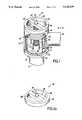
- FIG. 1is an isometric view, partially in section, of a pressure-type vacuum breaker of the invention
- FIG. 1ais a similar view of the bonnet of the vacuum breaker of FIG. 1;
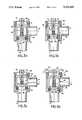
- FIG. 2is a side section view of the vacuum breaker of the invention taken at the line 2--2 of FIG. 1;
- FIG. 2ais a top section view of the vacuum breaker taken at the line 2a-2a in FIG. 2;
- FIGS. 3a, 3b, 3c and 3dare sequential side section views of a vacuum breaker of the invention in unpressurized state (FIG. 3a), during initial pressurization (FIG. 3b), in pressurized condition permitting flow (FIG. 3c) and in a depressurized condition permitting venting (FIG. 3d).
- a piston pressure-type vacuum breaker 10 of the inventionhas a housing 12 which defines an inlet 14, an outlet 16 and a vent opening 18.
- the housing 12further defines a central bore 17 within which is disposed a piston assembly 40.
- the vent opening 18is partially obstructed by a bonnet 20 (FIG. 1a).
- the bonnet 20has a threaded annular portion 22 which engages corresponding threads in the wall of the central bore 17 of housing 12 adjacent the vent opening 18.
- the threads 22permit the bonnet 20 to be removed, e.g. for maintenance of piston assembly 40, and then replaced.
- a strut 26extends fixedly across diameter of the bonnet 20 and defines two openings 28, 28' which permit air to pass through the bonnet 20 into the central bore 17 and which permit liquid to pass from the bore 17 out through the bonnet 20.
- At the center of the strut 26is a piston spring retaining neck 30, about which more will be said shortly.
- the piston assembly 40is located within the housing 12, and retained there by the bonnet 20.
- the piston assemblyconsists of an outer piston assembly 42 and an inner piston assembly 60.
- the outer piston assembly 42includes an upper vent valve 44, piston supports 48, an annular seal gasket retainer 50 and an annular valve gasket 52.
- the ends 49 of several piston supports 48are attached adjacent to the edge of the upper vent valve 44 and extend perpendicularly from the surface of the upper vent valve 44, which faces into the central bore 17.
- An inner piston guide 70extends from the surface of the upper vent valve 44, which faces the inner piston assembly 60.
- the annular gasket retainer 50is attached to the other end of the piston supports 48, and the annular valve gasket 52 is removably attached to the valve gasket retainer 50.
- the upper vent valve 44, piston supports 48, annular gasket retainer 50 and annular valve gasket 52define a piston assembly of generally cylindrical shape, with an axis concentric with the central bore 17 of the housing 12.
- the piston assembly 40is shorter in length than length of the central bore 17 of the housing 12 and so may move within the housing 12 in an axial direction (arrow A).
- the inner piston assembly 60consists of a check valve 80 and an inner piston compression spring 84. Assembly 60 is disposed concentric with the outer piston assembly 40 and moves along the axis of the outer piston assembly 40 (arrow A). In its lowest position, adjacent the valve gasket retainer 50, the inner check valve 80 abuts the valve gasket retainer 50 with o-ring seal 81 disposed therebetween to provide a seal and prevent water from flowing between the valve gasket retainer 50 and the inner check valve 80.
- the combination of inner check valve 80, valve gasket retainer 50 and annular valve gasket 52prevents water from flowing from the inlet 14 into the central bore 17 when the inner check valve 80 is adjacent to the valve gasket retainer 50.
- An annular cylinder 82extends from the surface of the inner check valve 80, which faces the upper vent valve 44, and is slidably mounted upon the inner check valve guide 70.
- the inner piston compression spring 84is positioned concentric with the inner check valve guide 70 and serves to bias the inner check valve 80 toward the valve gasket retainer 50.
- a piston spring 90is retained within the piston spring retaining neck 30, between the bonnet 20 and the upper vent valve 44.
- the piston springis a compression spring having a compression constant less than the inner piston compression spring 84, and serves to bias the piston assembly 40 toward the inlet 14.
- the piston spring 90biases the piston assembly 40 to the lowest position in the central bore 17, adjacent the inlet 14.
- the inner piston compression spring 84biases the inner check valve 80 against the valve gasket retainer 50. The position of the piston assembly 40 and the inner check valve 80 results in the inlet 14 being closed and the vent 18 open, with the outlet 16 at atmospheric pressure.
- the piston spring 90compresses, thereby permitting the piston assembly 40 to move toward the vent 18 (arrow U).
- the compression constant for the piston spring 90is less than the compression constant for the compression spring 84, so the compression spring 84 does not compress, but instead keeps the check valve 80 biased against the valve gasket retainer 50.
- the seal between the annular valve gasket 52/valve gasket retainer 50 and the wall of the bore 17e.g., an o-ring seal or a rolling diaphragm-type seal, not shown
- the o-ring seal 81 between the check valve 80 and the valve gasket retainer 50prevent water from the inlet 14 from flowing either to the outlet 16 or the vent 18.
Landscapes
- Health & Medical Sciences (AREA)
- Life Sciences & Earth Sciences (AREA)
- Engineering & Computer Science (AREA)
- Hydrology & Water Resources (AREA)
- Public Health (AREA)
- Water Supply & Treatment (AREA)
- Safety Valves (AREA)
- Check Valves (AREA)
- Self-Closing Valves And Venting Or Aerating Valves (AREA)
Abstract
Description
Claims (6)
Priority Applications (2)
| Application Number | Priority Date | Filing Date | Title |
|---|---|---|---|
| US07/643,750US5125429A (en) | 1991-01-23 | 1991-01-23 | Piston pressure-type vacuum breaker |
| AU10249/92AAU642374B2 (en) | 1991-01-23 | 1992-01-15 | Piston pressure-type vacuum breaker |
Applications Claiming Priority (1)
| Application Number | Priority Date | Filing Date | Title |
|---|---|---|---|
| US07/643,750US5125429A (en) | 1991-01-23 | 1991-01-23 | Piston pressure-type vacuum breaker |
Publications (1)
| Publication Number | Publication Date |
|---|---|
| US5125429Atrue US5125429A (en) | 1992-06-30 |
Family
ID=24582113
Family Applications (1)
| Application Number | Title | Priority Date | Filing Date |
|---|---|---|---|
| US07/643,750Expired - LifetimeUS5125429A (en) | 1991-01-23 | 1991-01-23 | Piston pressure-type vacuum breaker |
Country Status (2)
| Country | Link |
|---|---|
| US (1) | US5125429A (en) |
| AU (1) | AU642374B2 (en) |
Cited By (33)
| Publication number | Priority date | Publication date | Assignee | Title |
|---|---|---|---|---|
| US5492145A (en)* | 1993-08-20 | 1996-02-20 | Environmental System & Solutions, Inc. | Anti-syphon fluid control valve apparatus and method |
| US5584313A (en)* | 1995-12-01 | 1996-12-17 | Conbraco Industries, Inc. | Piston pressure-type vacuum breaker |
| US20040107993A1 (en)* | 2002-12-10 | 2004-06-10 | Alliance Laundry Systems Llc | Vacuum breaker with water leak containment device |
| US20050092946A1 (en)* | 2003-11-04 | 2005-05-05 | George Fellington | Automatically calibrating vacuum relief safety valve |
| US20060185731A1 (en)* | 2005-01-21 | 2006-08-24 | Zurn Industries, Inc. | Backflow preventor |
| US20090000667A1 (en)* | 2007-06-29 | 2009-01-01 | Cesare Bottura | Venting device |
| US20090057583A1 (en)* | 2007-08-27 | 2009-03-05 | Curtis Lee Van Weelden | Dual setpoint pressure controlled hydraulic valve |
| GB2468729A (en)* | 2009-03-17 | 2010-09-22 | Siegfried Schmidt | Transfer device for perpetual motion device |
| CN103133705A (en)* | 2013-03-18 | 2013-06-05 | 湖北拓宇水电科技有限公司 | Auto-exciting type differential action vacuum breaking valve |
| US20140373939A1 (en)* | 2013-06-25 | 2014-12-25 | Techspace Aero S.A. | Piston-Controlled Anti-Siphon Valve |
| USD721789S1 (en) | 2014-02-19 | 2015-01-27 | Watts Water Technologies, Inc. | Cartridge check assembly |
| USD724182S1 (en) | 2014-02-19 | 2015-03-10 | Watts Water Technologies, Inc. | Check retainer |
| USD729904S1 (en) | 2014-02-19 | 2015-05-19 | Watts Water Technologies, Inc. | Bonnet |
| USD738122S1 (en) | 2014-02-19 | 2015-09-08 | Watts Water Technologies, Inc. | Seat |
| US9504214B1 (en)* | 2014-10-06 | 2016-11-29 | Bryan L. Towsley | Anti-siphon valve with freeze protection |
| US9546475B2 (en) | 2014-02-19 | 2017-01-17 | Watts Water Technologies, Inc. | Valve member assembly |
| US9931449B2 (en) | 2015-05-29 | 2018-04-03 | Ameda, Inc. | Electrical breast pump and system |
| CN108252368A (en)* | 2018-04-04 | 2018-07-06 | 浙江三泉智能科技有限公司 | Air is every dirty device and intelligent closestool |
| US10716882B2 (en) | 2018-03-07 | 2020-07-21 | Ameda, Inc. | Apparatus and methods for universal breast pump kit |
| US20210108403A1 (en)* | 2019-10-15 | 2021-04-15 | Lixil Corporation | Toilet device |
| US11427992B2 (en) | 2019-12-10 | 2022-08-30 | Watts Regulator Co. | System for monitoring backflow preventer condition |
| US11448348B2 (en) | 2018-06-28 | 2022-09-20 | Watts Regulator Co. | Backflow prevention assembly having a variable lay-length and orientation |
| US11585077B2 (en) | 2020-08-19 | 2023-02-21 | Anderson Brass Company | Vacuum breaker valve with leak protection |
| US11585076B2 (en) | 2020-01-24 | 2023-02-21 | Watts Regulator Co. | Apparatus and method for valve cartridge extraction |
| US11650118B2 (en) | 2019-03-08 | 2023-05-16 | Watts Industries Italia S.R.L. | Differential pressure sensor with magnetic dial |
| US11674609B2 (en) | 2020-08-17 | 2023-06-13 | Watts Regulator Co. | Backflow prevention assembly with telescoping bias assembly and reversible valve member |
| US11739507B2 (en) | 2020-12-09 | 2023-08-29 | Watts Regulator Co. | Test cock with integrated extraction tool |
| US11773992B2 (en) | 2020-08-17 | 2023-10-03 | Watts Regulator Co. | Backflow prevention assembly with a linkage |
| US11795666B2 (en) | 2019-05-08 | 2023-10-24 | Watts Regulator Co. | Wireless communication system within a mechanical room |
| US11815424B2 (en) | 2019-05-08 | 2023-11-14 | Watts Regulator Co. | Backflow prevention system test cock with a fluid sensor |
| USD1021000S1 (en) | 2021-08-17 | 2024-04-02 | Watts Regulator Co. | Valve assembly and body for same |
| USD1032790S1 (en) | 2019-03-08 | 2024-06-25 | Watts Regulator Co. | Static balancing valve |
| US12195954B2 (en) | 2019-12-10 | 2025-01-14 | Watts Regulator Co. | System for monitoring backflow preventer condition |
Citations (13)
| Publication number | Priority date | Publication date | Assignee | Title |
|---|---|---|---|---|
| US2209189A (en)* | 1938-09-28 | 1940-07-23 | Bidoro Mfg Co Inc | Vacuum breaker valve |
| US2627278A (en)* | 1951-06-28 | 1953-02-03 | Shirley C Somers | Antisiphon valve |
| US2655171A (en)* | 1947-08-29 | 1953-10-13 | Jacob J Cantor | Vacuum breaker |
| US2960996A (en)* | 1957-05-07 | 1960-11-22 | Cherry Burrell Corp | Vacuum relief valve |
| US3083723A (en)* | 1959-11-04 | 1963-04-02 | Paul J Duchin | Vacuum breaker |
| US3180352A (en)* | 1962-05-04 | 1965-04-27 | Water Saver Faucet Co | Anti-siphon check valve |
| US3189037A (en)* | 1963-02-07 | 1965-06-15 | Callejo Modesto | Backflow preventer-vacuum breaker |
| US3286722A (en)* | 1964-07-27 | 1966-11-22 | Buckner Ind Inc | Vacuum breaker |
| DE2157363A1 (en)* | 1971-11-19 | 1973-05-24 | Guenter Preuss | PIPE BREAKER FOR LIQUID LINES |
| US3918477A (en)* | 1974-09-03 | 1975-11-11 | Surgical Mechanical Research I | Backflow preventing device |
| US4013088A (en)* | 1975-05-19 | 1977-03-22 | Braukmann Armaturen Ag | Valve structure |
| US4508137A (en)* | 1983-02-28 | 1985-04-02 | Kohler Co. | Wall mountable vacuum breaker |
| US4592382A (en)* | 1984-08-27 | 1986-06-03 | Aqua-Giene, Inc. | Anti-siphon nozzle |
- 1991
- 1991-01-23USUS07/643,750patent/US5125429A/ennot_activeExpired - Lifetime
- 1992
- 1992-01-15AUAU10249/92Apatent/AU642374B2/ennot_activeCeased
Patent Citations (13)
| Publication number | Priority date | Publication date | Assignee | Title |
|---|---|---|---|---|
| US2209189A (en)* | 1938-09-28 | 1940-07-23 | Bidoro Mfg Co Inc | Vacuum breaker valve |
| US2655171A (en)* | 1947-08-29 | 1953-10-13 | Jacob J Cantor | Vacuum breaker |
| US2627278A (en)* | 1951-06-28 | 1953-02-03 | Shirley C Somers | Antisiphon valve |
| US2960996A (en)* | 1957-05-07 | 1960-11-22 | Cherry Burrell Corp | Vacuum relief valve |
| US3083723A (en)* | 1959-11-04 | 1963-04-02 | Paul J Duchin | Vacuum breaker |
| US3180352A (en)* | 1962-05-04 | 1965-04-27 | Water Saver Faucet Co | Anti-siphon check valve |
| US3189037A (en)* | 1963-02-07 | 1965-06-15 | Callejo Modesto | Backflow preventer-vacuum breaker |
| US3286722A (en)* | 1964-07-27 | 1966-11-22 | Buckner Ind Inc | Vacuum breaker |
| DE2157363A1 (en)* | 1971-11-19 | 1973-05-24 | Guenter Preuss | PIPE BREAKER FOR LIQUID LINES |
| US3918477A (en)* | 1974-09-03 | 1975-11-11 | Surgical Mechanical Research I | Backflow preventing device |
| US4013088A (en)* | 1975-05-19 | 1977-03-22 | Braukmann Armaturen Ag | Valve structure |
| US4508137A (en)* | 1983-02-28 | 1985-04-02 | Kohler Co. | Wall mountable vacuum breaker |
| US4592382A (en)* | 1984-08-27 | 1986-06-03 | Aqua-Giene, Inc. | Anti-siphon nozzle |
Non-Patent Citations (2)
| Title |
|---|
| "Series 800 Anti-Siphon Pressure Type Vacuum Breakers", Watts Regulator Comany, PS-800-6, ES-800-6 898 IS-800-4, IS-800-4 881 (undated). |
| Series 800 Anti Siphon Pressure Type Vacuum Breakers , Watts Regulator Comany, PS 800 6, ES 800 6 898 IS 800 4, IS 800 4 881 (undated).* |
Cited By (51)
| Publication number | Priority date | Publication date | Assignee | Title |
|---|---|---|---|---|
| US5520367A (en)* | 1993-08-20 | 1996-05-28 | Environmental System & Solutions, Inc. | Anti-syphon fluid control valve apparatus and method |
| US5492145A (en)* | 1993-08-20 | 1996-02-20 | Environmental System & Solutions, Inc. | Anti-syphon fluid control valve apparatus and method |
| US5584313A (en)* | 1995-12-01 | 1996-12-17 | Conbraco Industries, Inc. | Piston pressure-type vacuum breaker |
| US20040107993A1 (en)* | 2002-12-10 | 2004-06-10 | Alliance Laundry Systems Llc | Vacuum breaker with water leak containment device |
| US6904931B2 (en) | 2002-12-10 | 2005-06-14 | Alliance Laundry Systems Llc | Vacuum breaker with water leak containment device |
| US20050092946A1 (en)* | 2003-11-04 | 2005-05-05 | George Fellington | Automatically calibrating vacuum relief safety valve |
| US7784483B2 (en) | 2005-01-21 | 2010-08-31 | Zurn Industries, Llc | Backflow preventer |
| US20060185731A1 (en)* | 2005-01-21 | 2006-08-24 | Zurn Industries, Inc. | Backflow preventor |
| US20090000667A1 (en)* | 2007-06-29 | 2009-01-01 | Cesare Bottura | Venting device |
| US7762273B2 (en)* | 2007-06-29 | 2010-07-27 | Olab S.R.L. | Venting device |
| US8056576B2 (en)* | 2007-08-27 | 2011-11-15 | Husco Automotive Holdings Llc | Dual setpoint pressure controlled hydraulic valve |
| US20090057583A1 (en)* | 2007-08-27 | 2009-03-05 | Curtis Lee Van Weelden | Dual setpoint pressure controlled hydraulic valve |
| GB2468729A (en)* | 2009-03-17 | 2010-09-22 | Siegfried Schmidt | Transfer device for perpetual motion device |
| CN103133705A (en)* | 2013-03-18 | 2013-06-05 | 湖北拓宇水电科技有限公司 | Auto-exciting type differential action vacuum breaking valve |
| US20140373939A1 (en)* | 2013-06-25 | 2014-12-25 | Techspace Aero S.A. | Piston-Controlled Anti-Siphon Valve |
| US9441746B2 (en)* | 2013-06-25 | 2016-09-13 | Techspace Aero S.A. | Piston-controlled anti-siphon valve |
| USD729904S1 (en) | 2014-02-19 | 2015-05-19 | Watts Water Technologies, Inc. | Bonnet |
| USD724182S1 (en) | 2014-02-19 | 2015-03-10 | Watts Water Technologies, Inc. | Check retainer |
| USD738122S1 (en) | 2014-02-19 | 2015-09-08 | Watts Water Technologies, Inc. | Seat |
| USD721789S1 (en) | 2014-02-19 | 2015-01-27 | Watts Water Technologies, Inc. | Cartridge check assembly |
| US9546475B2 (en) | 2014-02-19 | 2017-01-17 | Watts Water Technologies, Inc. | Valve member assembly |
| US9504214B1 (en)* | 2014-10-06 | 2016-11-29 | Bryan L. Towsley | Anti-siphon valve with freeze protection |
| US9894853B1 (en)* | 2014-10-06 | 2018-02-20 | Bryan L. Towsley | Anti-siphon valve with freeze protection |
| US9931449B2 (en) | 2015-05-29 | 2018-04-03 | Ameda, Inc. | Electrical breast pump and system |
| US10716882B2 (en) | 2018-03-07 | 2020-07-21 | Ameda, Inc. | Apparatus and methods for universal breast pump kit |
| CN108252368B (en)* | 2018-04-04 | 2024-04-26 | 厦门霖创卫浴有限公司 | Air dirt isolation device and intelligent closestool |
| CN108252368A (en)* | 2018-04-04 | 2018-07-06 | 浙江三泉智能科技有限公司 | Air is every dirty device and intelligent closestool |
| US12305782B2 (en) | 2018-06-28 | 2025-05-20 | Watts Regulator Co. | Backflow prevention assembly having a variable lay-length and orientation |
| US11448348B2 (en) | 2018-06-28 | 2022-09-20 | Watts Regulator Co. | Backflow prevention assembly having a variable lay-length and orientation |
| US11650118B2 (en) | 2019-03-08 | 2023-05-16 | Watts Industries Italia S.R.L. | Differential pressure sensor with magnetic dial |
| USD1032790S1 (en) | 2019-03-08 | 2024-06-25 | Watts Regulator Co. | Static balancing valve |
| US11815424B2 (en) | 2019-05-08 | 2023-11-14 | Watts Regulator Co. | Backflow prevention system test cock with a fluid sensor |
| US11795666B2 (en) | 2019-05-08 | 2023-10-24 | Watts Regulator Co. | Wireless communication system within a mechanical room |
| US12221776B2 (en) | 2019-05-08 | 2025-02-11 | Watts Regulator Co. | Wireless communication system within a mechanical room |
| US20210108403A1 (en)* | 2019-10-15 | 2021-04-15 | Lixil Corporation | Toilet device |
| US11427992B2 (en) | 2019-12-10 | 2022-08-30 | Watts Regulator Co. | System for monitoring backflow preventer condition |
| US12000123B2 (en) | 2019-12-10 | 2024-06-04 | Watts Regulator Co. | System for monitoring backflow preventer condition |
| US12195954B2 (en) | 2019-12-10 | 2025-01-14 | Watts Regulator Co. | System for monitoring backflow preventer condition |
| US11585076B2 (en) | 2020-01-24 | 2023-02-21 | Watts Regulator Co. | Apparatus and method for valve cartridge extraction |
| US12123510B2 (en) | 2020-08-17 | 2024-10-22 | Watts Regulator Co. | Compact valve assembly |
| US11852254B2 (en) | 2020-08-17 | 2023-12-26 | Watts Regulator Co. | Check valve cartridge with flow guide for compact backflow prevention assembly |
| US11835147B2 (en) | 2020-08-17 | 2023-12-05 | Watts Regulator Co. | Backflow prevention assembly having a cartridge with dual zone testing |
| US11674609B2 (en) | 2020-08-17 | 2023-06-13 | Watts Regulator Co. | Backflow prevention assembly with telescoping bias assembly and reversible valve member |
| US11773992B2 (en) | 2020-08-17 | 2023-10-03 | Watts Regulator Co. | Backflow prevention assembly with a linkage |
| US12181059B2 (en) | 2020-08-17 | 2024-12-31 | Watts Regulator Co. | Backflow prevention assembly having a cartridge with dual zone testing |
| US12181060B2 (en) | 2020-08-17 | 2024-12-31 | Watts Regulator Co. | Telescoping spring retention assembly for a check valve |
| US11821529B2 (en) | 2020-08-17 | 2023-11-21 | Watts Regulator Co. | Reversible spring retention assembly for a valve |
| US11719352B2 (en) | 2020-08-17 | 2023-08-08 | Watts Regulator Co. | Check cover assemblies for backflow prevention assemblies with integrated test cock protection shroud |
| US11585077B2 (en) | 2020-08-19 | 2023-02-21 | Anderson Brass Company | Vacuum breaker valve with leak protection |
| US11739507B2 (en) | 2020-12-09 | 2023-08-29 | Watts Regulator Co. | Test cock with integrated extraction tool |
| USD1021000S1 (en) | 2021-08-17 | 2024-04-02 | Watts Regulator Co. | Valve assembly and body for same |
Also Published As
| Publication number | Publication date |
|---|---|
| AU1024992A (en) | 1992-07-30 |
| AU642374B2 (en) | 1993-10-14 |
Similar Documents
| Publication | Publication Date | Title |
|---|---|---|
| US5125429A (en) | Piston pressure-type vacuum breaker | |
| US3659625A (en) | Drain valve device | |
| US4312374A (en) | Differential-pressure valve | |
| EP0216439B1 (en) | Non-flowing modulating pilot operated relief valve | |
| US4244392A (en) | Backflow prevention apparatus | |
| AU668609B2 (en) | Safety valve for high-pressure pumps, high-pressure water jet machines or the like | |
| US4531542A (en) | Fluid dampened back pressure regulator | |
| US4768542A (en) | Drain valve | |
| US5027852A (en) | Pilot valve for control valves and method of operation | |
| US4518006A (en) | Backflow-preventing valve | |
| US4825909A (en) | High pressure hydraulic flow control valve | |
| CA1213189A (en) | Automatic reservoir bleed valve | |
| US4171708A (en) | Bypass and unloader valve | |
| US6264436B1 (en) | Multifunction valve | |
| US3945401A (en) | Combination valve | |
| US5921274A (en) | Internal relief and bypass valve for pumps and piping systems | |
| US4385640A (en) | Hydraulic unloader | |
| US5305780A (en) | Pressure relief valve with auxiliary loading device | |
| CA1301018C (en) | Pressure regulating valve | |
| US4410005A (en) | Pilot operated relief valve | |
| US5090438A (en) | Self-relieving fluid regulator | |
| US4378932A (en) | Pressure responsive valve assembly | |
| US4757839A (en) | High pressure relief valve | |
| EP0159373B1 (en) | Positive displacement pump with frangible pressure relief disc assembly | |
| RU2006684C1 (en) | Pneumatic cylinder |
Legal Events
| Date | Code | Title | Description |
|---|---|---|---|
| AS | Assignment | Owner name:WATTS REGULATOR COMPANY, LAWRENCE, A CORP. OF MASS Free format text:ASSIGNMENT OF ASSIGNORS INTEREST.;ASSIGNORS:ACKROYD, RAND H.;HOFMANN, STEVEN P.;REEL/FRAME:005588/0779 Effective date:19910118 | |
| AS | Assignment | Owner name:WATTS INDUSTRIES, INC. A CORP. OF DELAWARE, MASSA Free format text:ASSIGNMENT OF ASSIGNORS INTEREST.;ASSIGNOR:WATTS REGULATOR COMPANY A CORP. OF MASSACHUSETTS;REEL/FRAME:006059/0474 Effective date:19910917 Owner name:WATTS INVESTMENT COMPANY A CORP. OF DELAWARE, DE Free format text:ASSIGNMENT OF ASSIGNORS INTEREST.;ASSIGNOR:WATTS INDUSTRIES, INC. A CORP. OF DELAWARE;REEL/FRAME:006059/0460 Effective date:19910917 | |
| STCF | Information on status: patent grant | Free format text:PATENTED CASE | |
| REMI | Maintenance fee reminder mailed | ||
| FPAY | Fee payment | Year of fee payment:4 | |
| SULP | Surcharge for late payment | ||
| REMI | Maintenance fee reminder mailed | ||
| FPAY | Fee payment | Year of fee payment:8 | |
| SULP | Surcharge for late payment | ||
| AS | Assignment | Owner name:WATTS REGULATOR CO., MASSACHUSETTS Free format text:ASSIGNMENT OF ASSIGNORS INTEREST;ASSIGNOR:WATTS INVESTMENT COMPANY;REEL/FRAME:010984/0496 Effective date:19991018 | |
| FEPP | Fee payment procedure | Free format text:PAYOR NUMBER ASSIGNED (ORIGINAL EVENT CODE: ASPN); ENTITY STATUS OF PATENT OWNER: LARGE ENTITY | |
| FPAY | Fee payment | Year of fee payment:12 |