US5124642A - Power line post insulator with dual inductor current sensor - Google Patents
Power line post insulator with dual inductor current sensorDownload PDFInfo
- Publication number
- US5124642A US5124642AUS07/455,523US45552389AUS5124642AUS 5124642 AUS5124642 AUS 5124642AUS 45552389 AUS45552389 AUS 45552389AUS 5124642 AUS5124642 AUS 5124642A
- Authority
- US
- United States
- Prior art keywords
- conductor
- recess
- axis
- inductive means
- coils
- Prior art date
- Legal status (The legal status is an assumption and is not a legal conclusion. Google has not performed a legal analysis and makes no representation as to the accuracy of the status listed.)
- Expired - Lifetime
Links
Images

Classifications
- G—PHYSICS
- G01—MEASURING; TESTING
- G01R—MEASURING ELECTRIC VARIABLES; MEASURING MAGNETIC VARIABLES
- G01R15/00—Details of measuring arrangements of the types provided for in groups G01R17/00 - G01R29/00, G01R33/00 - G01R33/26 or G01R35/00
- G01R15/14—Adaptations providing voltage or current isolation, e.g. for high-voltage or high-current networks
- G01R15/18—Adaptations providing voltage or current isolation, e.g. for high-voltage or high-current networks using inductive devices, e.g. transformers
Definitions
- This inventionrelates to power line post insulators, and particularly to line post insulators with means for sensing currents in conductors of power systems.
- Power line post insulatorssometimes utilize a coil in the vicinity of the current carrying conductor to sense the conductor's currents. While such sensors generally exhibit good sensitivity they are susceptible to noise from voltages induced by adjacent conductors, such as may exist in multi-phase systems. Toroidal coils have been suggested to overcome noise. Such sensors display excellent sensitivity and noise rejection but must surround the conductor and also are excessively bulky for use in a line post insulator.
- U.S. Pat. Nos. 4,700,123 and 4,859,925 of Thomas Belingdisclose line post insulators each having two current sensors that respond to currents in a conductor of a power system. According to these patents insulator housing surrounds two sensing coils on one side of the power conductor and the coils are connected subtractively to limit the noise generated by adjacent power lines in a multi-phase power system.
- Such devicesexhibit good rejection of noise from adjacent power lines but are comparatively insensitive because of the subtractive connection of the coils. They cause relatively high errors when used with power conductors whose diameters depart excessively from a predetermined diameter.
- An object of the inventionis to improve power line post insulators with means to sense currents in conductors of power systems.
- a line post insulatorincludes a housing with a recess for a power conductor, two inductive sensors located on opposite sides of the recess with axes parallel to each other and transverse to the direction of the conductor, and means for connecting the inductive sensors additively with respect to voltages induced by currents in the conductor.
- each inductive sensoris composed of a single coil.
- each inductive sensorincludes two coaxial coils.
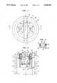
- FIG. 1is a top view of a device embodying features of the invention.
- FIG. 2is a section II--II of FIG. 1.
- FIG. 3is a schematic diagram showing details of the circuitry in FIG. 1 and 2.
- FIG. 4 and FIG. 7are sections of another device embodying features of the invention.
- FIG. 5is a schematic diagram illustrating circuitry in FIG. 4.
- FIG. 6is a schematic diagram of another embodiment of the invention.
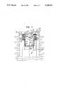
- a line post insulator 10includes a substantially cylindrical and hollow insulation housing 12 with an integral top 14, having a diametrical recess 16 that receives and supports a power conductor 20.
- a pair of inductive sensors 22 and 24are mounted in interior recesses 26 and 28 on axially opposite sides of the conductor 20.
- the inductive sensors 22 and 24are positioned to sense the varying fluxes which alternating currents through the conductor 20 generates circularly about the conductor.
- the currents through the conductorinduce voltages in the inductive sensors 23 and 24.
- the latterconstitute secondaries for the conductor 20 which acts as a primary.
- the inductive sensors 22 and 24include respective coils 32 and 34 having respective cores 36 and 38 and axes 40 and 42 parallel to the axis 44 of the housing 12.
- the axes 40 and 42are thus substantially transverse to the axis 46 of the conductor 20.
- the axial centers of the coils 32 and 34lie approximately at the same horizontal level as the center of the conductor 20.
- Conductive wires 48connect the coils 32 and 34 additively in series to produce a signal at terminal 50 and 52.
- FIG. 3shows the schematic diagram of the circuit of FIG. 2.
- the coils 32 and 34 in the insulation housing 12ideally assume positions as close as is possible to be symmetrical about the expected location of the axis 46 of the conductor 20, and to have axes tangential to the fluxes that flow circularly about the conductor 20.
- a pair of non-magnetic, non-ferrous, but conductive shields 66 and 68surround the respective inductive sensors 22 and 24 to shield the latter from the voltage of the conductor 20 and the voltage noise that may appear on the conductor.
- the shields 66 and 68shield the coils from the voltage stress field.
- Connecting lines 70ground the shields 66 and 68.
- the shields 66 and 68are in the form of non-magnetic, non-ferrous, but conductive cans. According to other embodiments they are in the form of screens or coatings.
- the currents passing through the conductor 20generate fluxes circularly about the conductor and induce currents in the coils 32 and 34.
- the wires 48connect the coils 32 and 34 additively and produce a signal proportional to the current in the conductor 20 at terminals 50 and 52.
- the circularly generated fluxmay extend upwardly with respect to the coil 32 and downwardly with respect to the coil 34.
- the dotted side of coils 32 and 34then may both appear positive.
- the additive connection of wires 48adds the induce voltages.
- the inventionhas the effect of maximizing the coupling between the primary formed by the conductor 20 and the secondaries formed by the inductive sensors 22 and 24, i.e. the coils 32 and 34. It reduces errors introduced by variations in cable size, cable droop, cable horizontal bend and cable vertical bend.
- the inventionalso reduces neighboring phase angle errors. That is, the conductor 20 induces voltages in the coils 32 and 34 in opposite directions because the coils straddle the conductor, and the circuitry 48 is arranged to add the induced voltages. However, the coils 32 and 34 do not straddle neighboring conductors, for example, conductors to the right or left of the insulator 10. Hence, these conductors induce noise voltages in the same direction i.e., both up or both down in the coils 32 and 34, and the lines 48 subtract these induced noise voltages.
- Conductors above and below the insulatorinduce comparatively small noise voltages because the coil 22, 24 axes extend substantially transverse to the circular flux which these conductors produce.
- the inventioncombines the noise reducing effects of horizontally neighboring and vertically neighboring conductors.
- the inventionis based upon the recognition that the inductive sensors 22 and 24, i.e. the coils 32 and 34, approximate portions of a toroid surrounding the conductor 20. Such a toroid would result in maximum coupling between the conductor 20 and the sensor.
- FIGS. 4 and 5Another embodiment of the invention appears in FIGS. 4 and 5.
- the inductive sensors 22 and 24each includes two coaxial coils 76, 78 and 80, 82 in series additive relation with respect to fluxes generated by the conductor 20.
- the two pairs of coils 76, 78 and 80, 82have the same advantages of the single pair of coils 32 and 34, but offer the additional advantage of more closely approximating the maximal toroidal condition.
- Each coil in FIGS. 4 and 5has a separate respective core 86, 88 and 90, 92. This embodiment offers the advantage of being less sensitive to differences in the diameters of various power conductors 20 which may be placed in the recess 16.
- FIG. 6Another embodiment of the invention appears in FIG. 6.
- the inductive sensors 22 and 24are composed of coils 92 and 94 which curve slightly about the axis 46 to approximate a toroid.
- Each coil 92 and 94has a separate core 96 and 98.
- Suitable bracketshold the inductive sensors 22 and 24 in the cans 60 and 68.
- Suitable known silicone rubber potting compoundshold the shields 66 and 68 in the recesses 26 and 28.
- a conductive coating 100covers the top 14 to control the voltage stress field which the voltage at the conductor 20 may create.
- the coating 100may also serve as a capacitor plate to couple to another conductive plate to measure the voltage of the conductor 20 relative to ground. Capacitor measurement is disclosed in the aforementioned U.S. Pat. No. of T. E. Beling No. 4,700,123 and No. 4,859,925.
- the conductive coating 100may be used as a capacitor plate to couple to the wire 70 to measure the voltage of the conductor 20 relative to ground. In that case, suitable current sensing means determine the current in the wire 70 as a measure of the voltage of the conductor 20 relative to ground.
- the coating 100is applicable to the structure both of FIG. 2 and FIG. 4.
- the coils 32 and 34are air coils without cores 36 and 38.
- the coils 76, 78 and 80, 82are air core and do not have cores 86, 88 and 90, 92.
- the center of the conductor 20is at the same horizontal level as the longitudinal centers of the coils 32 and 34, and in FIG. 4 the same level as the vertical centers between the coils 76 and 78 on the one hand and 80 and 82 on the other.
Landscapes
- Engineering & Computer Science (AREA)
- Power Engineering (AREA)
- Physics & Mathematics (AREA)
- General Physics & Mathematics (AREA)
- Measuring Instrument Details And Bridges, And Automatic Balancing Devices (AREA)
Abstract
Description
Claims (14)
Priority Applications (1)
| Application Number | Priority Date | Filing Date | Title |
|---|---|---|---|
| US07/455,523US5124642A (en) | 1989-12-21 | 1989-12-21 | Power line post insulator with dual inductor current sensor |
Applications Claiming Priority (1)
| Application Number | Priority Date | Filing Date | Title |
|---|---|---|---|
| US07/455,523US5124642A (en) | 1989-12-21 | 1989-12-21 | Power line post insulator with dual inductor current sensor |
Publications (1)
| Publication Number | Publication Date |
|---|---|
| US5124642Atrue US5124642A (en) | 1992-06-23 |
Family
ID=23809156
Family Applications (1)
| Application Number | Title | Priority Date | Filing Date |
|---|---|---|---|
| US07/455,523Expired - LifetimeUS5124642A (en) | 1989-12-21 | 1989-12-21 | Power line post insulator with dual inductor current sensor |
Country Status (1)
| Country | Link |
|---|---|
| US (1) | US5124642A (en) |
Cited By (41)
| Publication number | Priority date | Publication date | Assignee | Title |
|---|---|---|---|---|
| US5717326A (en)* | 1995-03-31 | 1998-02-10 | Moriwaki; Ikuo | Flat current sensor |
| WO1998020468A1 (en)* | 1996-11-01 | 1998-05-14 | Foster-Miller, Inc. | Modular core, self-powered powerline sensor |
| US5892430A (en)* | 1994-04-25 | 1999-04-06 | Foster-Miller, Inc. | Self-powered powerline sensor |
| US6043640A (en)* | 1997-10-29 | 2000-03-28 | Fluke Corporation | Multimeter with current sensor |
| US6259268B1 (en)* | 1999-04-02 | 2001-07-10 | National Semiconductor Corporation | Voltage stress testable embedded dual capacitor structure and process for its testing |
| US20010052843A1 (en)* | 1996-11-01 | 2001-12-20 | Richard M. Wiesman | Non-invasive powerline communications system |
| US6400130B2 (en)* | 1997-09-12 | 2002-06-04 | General Electric Company | Primary current conductor configurations for a residential electronic meter |
| EP1175623A4 (en)* | 1999-04-02 | 2003-01-15 | Lindsey Mfg Company | Insulator support current sensor |
| US6642704B2 (en)* | 2001-09-28 | 2003-11-04 | Eaton Corporation | Device for sensing electrical current and housing therefor |
| US6677743B1 (en) | 1999-03-05 | 2004-01-13 | Foster-Miller, Inc. | High voltage powerline sensor with a plurality of voltage sensing devices |
| US20050045359A1 (en)* | 2003-08-26 | 2005-03-03 | Michael Doogue | Current sensor |
| US20050146815A1 (en)* | 2003-12-11 | 2005-07-07 | Donovan David L. | Electrical, transmission/substation/distribution shunt capacitor switching and control system with integrated, automatically resettable, overcurrent protection |
| US20050156587A1 (en)* | 2004-01-16 | 2005-07-21 | Fieldmetrics Inc. | Current sensor |
| US20050224248A1 (en)* | 2003-08-26 | 2005-10-13 | Allegro Microsystems, Inc. | Current sensor |
| US20050248336A1 (en)* | 2003-08-26 | 2005-11-10 | Nirmal Sharma | Current sensor |
| US20060219436A1 (en)* | 2003-08-26 | 2006-10-05 | Taylor William P | Current sensor |
| WO2006078944A3 (en)* | 2005-01-19 | 2006-11-23 | Power Measurement Ltd | Sensor apparatus |
| US20070063689A1 (en)* | 2005-09-21 | 2007-03-22 | Universal Enterprises, Incorporated | Current measuring device |
| WO2007085278A1 (en)* | 2006-01-24 | 2007-08-02 | Sentec Ltd. | Current sensor |
| US20090058412A1 (en)* | 2006-05-12 | 2009-03-05 | Taylor William P | Integrated Current Sensor |
| US20100019332A1 (en)* | 2008-07-24 | 2010-01-28 | Taylor William P | Methods and apparatus for integrated circuit having on chip capacitor with eddy current reductions |
| US20110133732A1 (en)* | 2009-12-03 | 2011-06-09 | Allegro Microsystems, Inc. | Methods and apparatus for enhanced frequency response of magnetic sensors |
| CN103023303A (en)* | 2011-09-23 | 2013-04-03 | 通用电气公司 | Current transformer assembly for use with electrical monitoring systems and methods of assembling same |
| US8629539B2 (en) | 2012-01-16 | 2014-01-14 | Allegro Microsystems, Llc | Methods and apparatus for magnetic sensor having non-conductive die paddle |
| US8907437B2 (en) | 2011-07-22 | 2014-12-09 | Allegro Microsystems, Llc | Reinforced isolation for current sensor with magnetic field transducer |
| US9190606B2 (en) | 2013-03-15 | 2015-11-17 | Allegro Micosystems, LLC | Packaging for an electronic device |
| US9411025B2 (en) | 2013-04-26 | 2016-08-09 | Allegro Microsystems, Llc | Integrated circuit package having a split lead frame and a magnet |
| WO2016125028A3 (en)* | 2015-02-03 | 2016-10-13 | Abb Technology Ltd. | System for monitoring electrical power transmission line |
| US9494660B2 (en) | 2012-03-20 | 2016-11-15 | Allegro Microsystems, Llc | Integrated circuit package having a split lead frame |
| US9666788B2 (en) | 2012-03-20 | 2017-05-30 | Allegro Microsystems, Llc | Integrated circuit package having a split lead frame |
| US9812588B2 (en) | 2012-03-20 | 2017-11-07 | Allegro Microsystems, Llc | Magnetic field sensor integrated circuit with integral ferromagnetic material |
| US20180017599A1 (en)* | 2015-05-28 | 2018-01-18 | Murata Manufacturing Co., Ltd. | Current detection element, transmission device, and electric power transmission system |
| US20180136263A1 (en)* | 2016-11-11 | 2018-05-17 | Fluke Corporation | Non-contact voltage measurement system using multiple capacitors |
| US10234513B2 (en) | 2012-03-20 | 2019-03-19 | Allegro Microsystems, Llc | Magnetic field sensor integrated circuit with integral ferromagnetic material |
| US10345343B2 (en) | 2013-03-15 | 2019-07-09 | Allegro Microsystems, Llc | Current sensor isolation |
| US10352967B2 (en) | 2016-11-11 | 2019-07-16 | Fluke Corporation | Non-contact electrical parameter measurement systems |
| US10573455B2 (en)* | 2015-11-18 | 2020-02-25 | The University Of Hong Kong | Wireless power transfer system |
| US10991644B2 (en) | 2019-08-22 | 2021-04-27 | Allegro Microsystems, Llc | Integrated circuit package having a low profile |
| US11644485B2 (en) | 2021-10-07 | 2023-05-09 | Allegro Microsystems, Llc | Current sensor integrated circuits |
| US11768230B1 (en) | 2022-03-30 | 2023-09-26 | Allegro Microsystems, Llc | Current sensor integrated circuit with a dual gauge lead frame |
| US11800813B2 (en) | 2020-05-29 | 2023-10-24 | Allegro Microsystems, Llc | High isolation current sensor |
Citations (5)
| Publication number | Priority date | Publication date | Assignee | Title |
|---|---|---|---|---|
| SU290223A1 (en)* | ||||
| US3251014A (en)* | 1964-01-16 | 1966-05-10 | Sigma Instruments Inc | Electrical coupling device |
| US3386059A (en)* | 1965-10-21 | 1968-05-28 | Sigma Instruments Inc | Power line coupling device |
| US4717872A (en)* | 1985-01-28 | 1988-01-05 | Watt Watcher Inc. | Device for monitoring consumption of electrical power |
| US4839600A (en)* | 1986-01-10 | 1989-06-13 | Kuurstra John C | Ammeter for use with A.C. electric power lines |
- 1989
- 1989-12-21USUS07/455,523patent/US5124642A/ennot_activeExpired - Lifetime
Patent Citations (5)
| Publication number | Priority date | Publication date | Assignee | Title |
|---|---|---|---|---|
| SU290223A1 (en)* | ||||
| US3251014A (en)* | 1964-01-16 | 1966-05-10 | Sigma Instruments Inc | Electrical coupling device |
| US3386059A (en)* | 1965-10-21 | 1968-05-28 | Sigma Instruments Inc | Power line coupling device |
| US4717872A (en)* | 1985-01-28 | 1988-01-05 | Watt Watcher Inc. | Device for monitoring consumption of electrical power |
| US4839600A (en)* | 1986-01-10 | 1989-06-13 | Kuurstra John C | Ammeter for use with A.C. electric power lines |
Cited By (79)
| Publication number | Priority date | Publication date | Assignee | Title |
|---|---|---|---|---|
| US5892430A (en)* | 1994-04-25 | 1999-04-06 | Foster-Miller, Inc. | Self-powered powerline sensor |
| US5717326A (en)* | 1995-03-31 | 1998-02-10 | Moriwaki; Ikuo | Flat current sensor |
| WO1998020468A1 (en)* | 1996-11-01 | 1998-05-14 | Foster-Miller, Inc. | Modular core, self-powered powerline sensor |
| US7158012B2 (en) | 1996-11-01 | 2007-01-02 | Foster-Miller, Inc. | Non-invasive powerline communications system |
| AU725071B2 (en)* | 1996-11-01 | 2000-10-05 | Foster-Miller Inc. | Modular core, self-powered powerline sensor |
| US20010052843A1 (en)* | 1996-11-01 | 2001-12-20 | Richard M. Wiesman | Non-invasive powerline communications system |
| US6400130B2 (en)* | 1997-09-12 | 2002-06-04 | General Electric Company | Primary current conductor configurations for a residential electronic meter |
| US6043640A (en)* | 1997-10-29 | 2000-03-28 | Fluke Corporation | Multimeter with current sensor |
| US6677743B1 (en) | 1999-03-05 | 2004-01-13 | Foster-Miller, Inc. | High voltage powerline sensor with a plurality of voltage sensing devices |
| EP1175623A4 (en)* | 1999-04-02 | 2003-01-15 | Lindsey Mfg Company | Insulator support current sensor |
| US6555999B1 (en) | 1999-04-02 | 2003-04-29 | Lindsey Manufacturing Company | Insulator support current sensor |
| US6259268B1 (en)* | 1999-04-02 | 2001-07-10 | National Semiconductor Corporation | Voltage stress testable embedded dual capacitor structure and process for its testing |
| US6642704B2 (en)* | 2001-09-28 | 2003-11-04 | Eaton Corporation | Device for sensing electrical current and housing therefor |
| US20060219436A1 (en)* | 2003-08-26 | 2006-10-05 | Taylor William P | Current sensor |
| US7166807B2 (en)* | 2003-08-26 | 2007-01-23 | Allegro Microsystems, Inc. | Current sensor |
| US20050224248A1 (en)* | 2003-08-26 | 2005-10-13 | Allegro Microsystems, Inc. | Current sensor |
| US20050248336A1 (en)* | 2003-08-26 | 2005-11-10 | Nirmal Sharma | Current sensor |
| US6995315B2 (en)* | 2003-08-26 | 2006-02-07 | Allegro Microsystems, Inc. | Current sensor |
| US7598601B2 (en) | 2003-08-26 | 2009-10-06 | Allegro Microsystems, Inc. | Current sensor |
| US20050045359A1 (en)* | 2003-08-26 | 2005-03-03 | Michael Doogue | Current sensor |
| US20080297138A1 (en)* | 2003-08-26 | 2008-12-04 | Taylor William P | Current sensor |
| US7709754B2 (en) | 2003-08-26 | 2010-05-04 | Allegro Microsystems, Inc. | Current sensor |
| US20050146815A1 (en)* | 2003-12-11 | 2005-07-07 | Donovan David L. | Electrical, transmission/substation/distribution shunt capacitor switching and control system with integrated, automatically resettable, overcurrent protection |
| US7279884B2 (en) | 2004-01-16 | 2007-10-09 | Field Metrics, Inc | Temperature compensated and self-calibrated current sensor using reference magnetic field |
| US7279885B2 (en) | 2004-01-16 | 2007-10-09 | Field Metrics, Inc | Temperature compensated current sensor using reference magnetic field |
| US20070057662A1 (en)* | 2004-01-16 | 2007-03-15 | Fieldmetrics Inc. | Temperature Compensated and Self-Calibrated Current Sensor using Reference Magnetic Field |
| US20070063691A1 (en)* | 2004-01-16 | 2007-03-22 | Fieldmetrics Inc. | Temperature Compensated and Self-Calibrated Current Sensor |
| US7321226B2 (en) | 2004-01-16 | 2008-01-22 | Fieldmetrics, Inc | Temperature compensated and self-calibrated current sensor using reference current |
| US7164263B2 (en) | 2004-01-16 | 2007-01-16 | Fieldmetrics, Inc. | Current sensor |
| US20070205749A1 (en)* | 2004-01-16 | 2007-09-06 | Fieldmetrics Inc. | Temperature Compensated and Self-Calibrated Current Sensor using Reference Current |
| US20070205750A1 (en)* | 2004-01-16 | 2007-09-06 | Fieldmetrics Inc. | Temperature Compensated Current Sensor using Reference Magnetic Field |
| US7274186B2 (en) | 2004-01-16 | 2007-09-25 | Fieldmetrics, Inc | Temperature compensated and self-calibrated current sensor |
| US20050156587A1 (en)* | 2004-01-16 | 2005-07-21 | Fieldmetrics Inc. | Current sensor |
| US20060284647A1 (en)* | 2005-01-19 | 2006-12-21 | Gunn Colin N | Sensor apparatus |
| US20060279910A1 (en)* | 2005-01-19 | 2006-12-14 | Gunn Colin N | Current sensor assembly |
| WO2006078944A3 (en)* | 2005-01-19 | 2006-11-23 | Power Measurement Ltd | Sensor apparatus |
| US7557563B2 (en) | 2005-01-19 | 2009-07-07 | Power Measurement Ltd. | Current sensor assembly |
| US20070063689A1 (en)* | 2005-09-21 | 2007-03-22 | Universal Enterprises, Incorporated | Current measuring device |
| US7327133B2 (en)* | 2005-09-21 | 2008-02-05 | Universal Enterprises, Inc. | Current measuring device using hall sensors |
| CN101336378A (en)* | 2006-01-24 | 2008-12-31 | 森泰克有限公司 | Current sensor |
| WO2007085278A1 (en)* | 2006-01-24 | 2007-08-02 | Sentec Ltd. | Current sensor |
| US8080994B2 (en) | 2006-05-12 | 2011-12-20 | Allegro Microsystems, Inc. | Integrated current sensor |
| US20090058412A1 (en)* | 2006-05-12 | 2009-03-05 | Taylor William P | Integrated Current Sensor |
| US20100019332A1 (en)* | 2008-07-24 | 2010-01-28 | Taylor William P | Methods and apparatus for integrated circuit having on chip capacitor with eddy current reductions |
| US8093670B2 (en) | 2008-07-24 | 2012-01-10 | Allegro Microsystems, Inc. | Methods and apparatus for integrated circuit having on chip capacitor with eddy current reductions |
| US20110133732A1 (en)* | 2009-12-03 | 2011-06-09 | Allegro Microsystems, Inc. | Methods and apparatus for enhanced frequency response of magnetic sensors |
| US8907437B2 (en) | 2011-07-22 | 2014-12-09 | Allegro Microsystems, Llc | Reinforced isolation for current sensor with magnetic field transducer |
| CN103023303A (en)* | 2011-09-23 | 2013-04-03 | 通用电气公司 | Current transformer assembly for use with electrical monitoring systems and methods of assembling same |
| US8502554B2 (en)* | 2011-09-23 | 2013-08-06 | General Electric Company | Current transformer assembly for use with electrical monitoring systems and methods of assembling same |
| US9620705B2 (en) | 2012-01-16 | 2017-04-11 | Allegro Microsystems, Llc | Methods and apparatus for magnetic sensor having non-conductive die paddle |
| US10333055B2 (en) | 2012-01-16 | 2019-06-25 | Allegro Microsystems, Llc | Methods for magnetic sensor having non-conductive die paddle |
| US9299915B2 (en) | 2012-01-16 | 2016-03-29 | Allegro Microsystems, Llc | Methods and apparatus for magnetic sensor having non-conductive die paddle |
| US8629539B2 (en) | 2012-01-16 | 2014-01-14 | Allegro Microsystems, Llc | Methods and apparatus for magnetic sensor having non-conductive die paddle |
| US9666788B2 (en) | 2012-03-20 | 2017-05-30 | Allegro Microsystems, Llc | Integrated circuit package having a split lead frame |
| US9494660B2 (en) | 2012-03-20 | 2016-11-15 | Allegro Microsystems, Llc | Integrated circuit package having a split lead frame |
| US11677032B2 (en) | 2012-03-20 | 2023-06-13 | Allegro Microsystems, Llc | Sensor integrated circuit with integrated coil and element in central region of mold material |
| US11961920B2 (en) | 2012-03-20 | 2024-04-16 | Allegro Microsystems, Llc | Integrated circuit package with magnet having a channel |
| US9812588B2 (en) | 2012-03-20 | 2017-11-07 | Allegro Microsystems, Llc | Magnetic field sensor integrated circuit with integral ferromagnetic material |
| US11828819B2 (en) | 2012-03-20 | 2023-11-28 | Allegro Microsystems, Llc | Magnetic field sensor integrated circuit with integral ferromagnetic material |
| US11444209B2 (en) | 2012-03-20 | 2022-09-13 | Allegro Microsystems, Llc | Magnetic field sensor integrated circuit with an integrated coil enclosed with a semiconductor die by a mold material |
| US10916665B2 (en) | 2012-03-20 | 2021-02-09 | Allegro Microsystems, Llc | Magnetic field sensor integrated circuit with an integrated coil |
| US10230006B2 (en) | 2012-03-20 | 2019-03-12 | Allegro Microsystems, Llc | Magnetic field sensor integrated circuit with an electromagnetic suppressor |
| US10234513B2 (en) | 2012-03-20 | 2019-03-19 | Allegro Microsystems, Llc | Magnetic field sensor integrated circuit with integral ferromagnetic material |
| US9865807B2 (en) | 2013-03-15 | 2018-01-09 | Allegro Microsystems, Llc | Packaging for an electronic device |
| US10345343B2 (en) | 2013-03-15 | 2019-07-09 | Allegro Microsystems, Llc | Current sensor isolation |
| US9190606B2 (en) | 2013-03-15 | 2015-11-17 | Allegro Micosystems, LLC | Packaging for an electronic device |
| US10753963B2 (en) | 2013-03-15 | 2020-08-25 | Allegro Microsystems, Llc | Current sensor isolation |
| US9411025B2 (en) | 2013-04-26 | 2016-08-09 | Allegro Microsystems, Llc | Integrated circuit package having a split lead frame and a magnet |
| WO2016125028A3 (en)* | 2015-02-03 | 2016-10-13 | Abb Technology Ltd. | System for monitoring electrical power transmission line |
| US20180017599A1 (en)* | 2015-05-28 | 2018-01-18 | Murata Manufacturing Co., Ltd. | Current detection element, transmission device, and electric power transmission system |
| US10459010B2 (en)* | 2015-05-28 | 2019-10-29 | Murata Manufacturing Co., Ltd. | Current detection element including a coil-shaped current detection conductor, transmission device, and electric power transmission system |
| US10573455B2 (en)* | 2015-11-18 | 2020-02-25 | The University Of Hong Kong | Wireless power transfer system |
| US20180136263A1 (en)* | 2016-11-11 | 2018-05-17 | Fluke Corporation | Non-contact voltage measurement system using multiple capacitors |
| US10281503B2 (en)* | 2016-11-11 | 2019-05-07 | Fluke Corporation | Non-contact voltage measurement system using multiple capacitors |
| US10352967B2 (en) | 2016-11-11 | 2019-07-16 | Fluke Corporation | Non-contact electrical parameter measurement systems |
| US10991644B2 (en) | 2019-08-22 | 2021-04-27 | Allegro Microsystems, Llc | Integrated circuit package having a low profile |
| US11800813B2 (en) | 2020-05-29 | 2023-10-24 | Allegro Microsystems, Llc | High isolation current sensor |
| US11644485B2 (en) | 2021-10-07 | 2023-05-09 | Allegro Microsystems, Llc | Current sensor integrated circuits |
| US11768230B1 (en) | 2022-03-30 | 2023-09-26 | Allegro Microsystems, Llc | Current sensor integrated circuit with a dual gauge lead frame |
Similar Documents
| Publication | Publication Date | Title |
|---|---|---|
| US5124642A (en) | Power line post insulator with dual inductor current sensor | |
| US6563296B2 (en) | Closely-coupled multiple-winding magnetic induction-type sensor | |
| US3374434A (en) | Inductive coupling apparatus for use in coupling to underwater electric systems and the like | |
| FR2584193B1 (en) | INDUCTIVE SENSOR FOR CURRENT MEASUREMENT | |
| GB1078459A (en) | Improvements in/or relating to apparatus for detecting or measuring alternating currents | |
| US3312898A (en) | Polyphase current measuring device using several signal detectors each positioned to respond to only one phase current magnetic field | |
| US4700131A (en) | Mutual inductor current sensor | |
| US20020125978A1 (en) | Three-phase current transformer | |
| US4700123A (en) | Power distribution systems and means for control thereof | |
| EP0851442B1 (en) | Lead-in insulator | |
| KR890015026A (en) | Mutual inductance current transducer, manufacturing method and electric energy meter | |
| RU2129285C1 (en) | Tap-off of high-frequency signal of error from high- frequency electromagnetic field in high-power electric machine | |
| EP0446496A2 (en) | Shielded magnetizing device and angular rate sensor in which such a device is used | |
| JP2001033490A5 (en) | ||
| SU1416919A1 (en) | Current transducer | |
| SU1117556A2 (en) | Pickup for electric prospecting equipment | |
| SU466436A1 (en) | Sensor components of the vector strength of an alternating electric field | |
| CN112437882A (en) | Split core current sensor | |
| SU1068819A2 (en) | Device for measuring electroconductive liquid flow speed | |
| JPS60203863A (en) | Gas-insulated three-phase current transformer | |
| SU1394066A1 (en) | Device for measuring temperature of windings of h.v. transformers | |
| SU991541A2 (en) | Magnetosensitive element for starting remote relay protection system | |
| SU1206734A1 (en) | Reference standard of magnetic induction | |
| KR910001068Y1 (en) | Transformer for earth resistance measurement | |
| SU1756193A1 (en) | Inductive sensor for automatic locomotive signalling |
Legal Events
| Date | Code | Title | Description |
|---|---|---|---|
| AS | Assignment | Owner name:SIGMA INSTRUMENTS, INC., MASSACHUSETTS Free format text:ASSIGNMENT OF ASSIGNORS INTEREST.;ASSIGNOR:MARX, THOMAS I.;REEL/FRAME:005245/0407 Effective date:19900122 | |
| STCF | Information on status: patent grant | Free format text:PATENTED CASE | |
| FPAY | Fee payment | Year of fee payment:4 | |
| FEPP | Fee payment procedure | Free format text:PAYOR NUMBER ASSIGNED (ORIGINAL EVENT CODE: ASPN); ENTITY STATUS OF PATENT OWNER: LARGE ENTITY | |
| FPAY | Fee payment | Year of fee payment:8 | |
| REMI | Maintenance fee reminder mailed | ||
| FPAY | Fee payment | Year of fee payment:12 | |
| SULP | Surcharge for late payment | Year of fee payment:11 | |
| AS | Assignment | Owner name:JOSLYN HI-VOLTAGE COMPANY, LLC, OHIO Free format text:ASSIGNMENT OF ASSIGNORS INTEREST;ASSIGNOR:PACIFIC SCIENTIFIC COMPANY, LLC;REEL/FRAME:019795/0105 Effective date:20070724 | |
| AS | Assignment | Owner name:THOMAS & BETTS CORPORATION, TENNESSEE Free format text:CHANGE OF NAME;ASSIGNOR:SIGMA INSTRUMENTS, INC.;REEL/FRAME:019930/0899 Effective date:20071002 | |
| AS | Assignment | Owner name:THOMAS & BETTS INTERNATIONAL, INC., DELAWARE Free format text:ASSIGNMENT OF ASSIGNORS INTEREST;ASSIGNOR:JOSLYN HI-VOLTAGE COMPANY, LLC;REEL/FRAME:020143/0756 Effective date:20071108 |