US5124524A - Laser alignment and control system - Google Patents
Laser alignment and control systemDownload PDFInfo
- Publication number
- US5124524A US5124524AUS07/614,376US61437690AUS5124524AUS 5124524 AUS5124524 AUS 5124524AUS 61437690 AUS61437690 AUS 61437690AUS 5124524 AUS5124524 AUS 5124524A
- Authority
- US
- United States
- Prior art keywords
- relative
- axis
- laser
- frame
- frame means
- Prior art date
- Legal status (The legal status is an assumption and is not a legal conclusion. Google has not performed a legal analysis and makes no representation as to the accuracy of the status listed.)
- Expired - Lifetime
Links
Images


Classifications
- G—PHYSICS
- G01—MEASURING; TESTING
- G01B—MEASURING LENGTH, THICKNESS OR SIMILAR LINEAR DIMENSIONS; MEASURING ANGLES; MEASURING AREAS; MEASURING IRREGULARITIES OF SURFACES OR CONTOURS
- G01B11/00—Measuring arrangements characterised by the use of optical techniques
- G01B11/002—Measuring arrangements characterised by the use of optical techniques for measuring two or more coordinates
- G01B11/005—Measuring arrangements characterised by the use of optical techniques for measuring two or more coordinates coordinate measuring machines
Definitions
- the present inventionrelates to three dimensional digital mapping, and more particularly to devices for controllably directing laser energy upon objects in the course of mapping surface contours of the objects.
- Three dimensional laser digitizingis known as an effective technique for collecting information about the surface contours of an object under study Typically a laser beam is directed onto the surface of the object Reflected light is measured to obtain information about the surface contours The information is translated to digital information, from which a wire-frame image of the object can be projected onto a video display terminal.
- Three dimensional laser digitizingaffords substantial advantages over earlier topography measurement schemes involving a contact probe or stylus Laser digitizing involves no contact with the object being measured, and enables surface measurement of soft and fragile objects (e.g. models of clay or flexible foam) without the possibility of damaging the object or distorting the surface Laser systems also afford higher resolution and accuracy, and require no offset calculations.
- One of the more challenging aspects in laser digitizingconcerns objects with complex, irregular surface topographies.
- Some point-range laser probesare capable of precision measurement even when the laser beam is substantially offset from perpendicular to the surface under scan. Nonetheless, imaging is enhanced and digital data more reliable, when the laser beam can be positioned approximately perpendicular to such surface.
- Another object of the inventionis to provide a means for positioning a laser beam parallel to any vector in a two dimensional space, based on three mutually perpendicular linear translation axes and one rotational axis.
- Yet another object of the present inventionis to provide a laser support head adapted for mounting to a precision machining apparatus, with at least one rotational axis and means for precision aligning each rotational axis relative to the machining system.
- an apparatus for supporting the laser for controlled translation and rotationincludes a stationary base having a reference surface that defines a reference plane. Means are provided for mounting a rigid support member for linear translation in mutually perpendicular first, second and third directions. The first and second directions are parallel to the reference surface and the third direction is perpendicular to the reference surface.
- a laser mounting meansadjustably secures a laser energy source with respect to the rigid support member.
- the laser mounting meansincludes a rigid support means integral with the laser energy source, a rigid first frame means, and a first coupling means for joining the support means to the first frame means for pivotal movement relative to the first frame means on a first adjustment axis parallel to the reference plane, and for linear translation relative to the first frame means along the first adjustment axis.
- a first adjustment meansadjustably fixes the linear position of the support means relative to the first frame means
- a second adjustment meansadjustably fixes the angular position of the support means relative to the first frame means.
- the laser mounting meansfurther includes a second, coupling means for joining the first frame means for rotation relative to the support member about a first rotational axis parallel to the reference plane.
- the apparatusfurther includes a first drive means for controllably moving the support member in the first, second and third directions, and a second drive means for rotating the first frame means relative to the support member.
- the first rotation axisis perpendicular to the first adjustment axis.
- the first frame meansincludes a substantially flat support plate having a major plane at least approximately perpendicular to the first rotational axis.
- the support meansincludes a substantially flat pivot plate spaced apart from the support plate in the direction of the first rotational axis and at least approximately parallel to the support plate.
- the coupling meanscan include a pair first channels in the support plate, elongate and spaced apart from one another in the direction of the first adjustment axis, a pair of hemispherical second channels, each opposed to one of the first channels, a spherical bearing contained in each opposed pair of channels, and a biasing means such as a spring in tension joined to the support plate and pivot plate to bias the plates toward one another and thus retain the bearings.
- a rod, threadedly engaged within the pivot plate and engaged with the support plateis rotatable to move the pivot plate linearly relative to the support plate, to provide the first adjustment means.
- a second adjustment meanslikewise can include a threaded member engaged within the pivot plate. In this case, the threaded member extends in the direction of the first rotational axis and engages the support plate, with a spring means biasing the pivot plate and support plate angularly towards one another.
- the coupling means and adjustment meansenable a precision alignment of the laser source with respect to the reference plane. More particularly, the support means supporting the laser can be aligned to position the laser beam angularly to be perpendicular to the first rotational axis, and further aligned to linearly position the laser beam so that it intersects the first rotational axis.
- the support means supporting the lasercan be aligned to position the laser beam angularly to be perpendicular to the first rotational axis, and further aligned to linearly position the laser beam so that it intersects the first rotational axis.
- the laser probeis movable linearly throughout a three dimensional space, and further can be rotated about the first rotational axis to position the laser beam parallel to any vector in a two dimensional space. Regardless of the laser probe position or angular orientation, the beam intersects and remains perpendicular to the first rotational axis.
- the laser mounting meansfurther includes a third coupling means for joining the first frame means to the support member for linear translation, relative to the support member, along a second adjustment axis parallel to the reference plane and angularly offset from (preferably perpendicular to) the first adjustment axis.
- a fourth coupling meansjoins the first frame means for rotation relative to the support member about a second rotational axis perpendicular to the reference plane.
- a third drive meansis provided to rotate the first frame means about the second rotational axis.
- a third adjustment meansadjustably fixes the linear position of the first frame means relative to the support member along the second adjustment axis.
- the support meansis again adjustably positioned so that the laser beam is perpendicular to and intersects the first rotational axis. Further, however, the beam is translated linearly to coincide with the second rotational axis. Accordingly, the beam remains perpendicular to the first rotation axis and coincident with the second rotation axis regardless of the location or angular orientation of the laser probe. This enables an automatic scan in which the laser beam can be positioned parallel to any vector in a three dimensional space.
- the present inventionaffords a substantial advantage in that the laser beam can be appropriately positioned and oriented with respect to virtually any point on the surface of any object, regardless of convolutions, irregularities and other complexities in the topography of the object.
- the enhanced laser positioningaffords more accurate and reliable data representing the topography, leading to more accurate replication of the object in a scan-line pattern.
- FIG. 1is a schematic view of a laser probe scanning the surface of an object in a three dimensional digitizing process
- FIG. 2is a schematic view of an apparatus for supporting a laser probe and an object for scanning, in accordance with the present invention
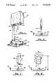
- FIG. 3is a prospective view of the probe assembly of FIG. 2;
- FIG. 4is a forward elevation of the probe assembly
- FIG. 5is sectional view taken along the line 5--5 in FIG. 4;
- FIG. 6is a sectional view taken along the line 6--6 in Figure
- FIGS. 7 and 8are schematic representations of aligning the first embodiment probe assembly
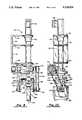
- FIG. 9is a side elevation of a second embodiment head assembly constructed in accordance with the present invention.
- FIG. 10is a front elevation of the probe assembly of FIG. 9.
- FIG. 11is a schematic representation of alignment of the second embodiment probe assembly.
- FIG. 1a laser camera or laser probe 16 supported in spaced apart relation to a base 18 having a planar, horizontal reference surface 20.
- An object 22is at rest on the reference surface.
- Laser probe 16includes a casing 24 surrounding a source of laser energy.
- a laser beam 26, produced by the laser sourceis emitted beyond the housing through a laser source aperture 28, and onto the exposed exterior surface 30 of object 22 at a point or region 32, from which the beam is reflected back to the probe through a receiving aperture 34.
- Any change in the distance D between probe 16 and surface 30is determined by triangulation, based on a corresponding change in the angle A between laser beam 26 and the reflected beam.
- Probe 16is movable longitudinally and transversely of object 22, and information is acquired based on thousands of points such as point 32. In a known manner not further discussed in this application, information from these multiple points is converted to digital information based on three dimensional coordinates, and then can be used to create a scan-line pattern that replicates the surface contours or topography of the object under scan.
- FIG. 2shows a three dimensional digitizing system 36 in which a laser probe head assembly 38 is supported for a linear translation along three mutually perpendicular axes including a horizontal X axis, a horizontal Y axis and a vertical Z axis. Probe assembly 38 further rotates a laser probe about a V axis, preferably parallel to the Y axis.
- System 36includes a rigid base 40 having a planar, horizontal surface 42 which forms a reference plane.
- a first support stage 44is supported on the base for movement in the Y direction along a pair of opposed, parallel tracks 46 and 48, controlled by a servo motor 50.
- a second support stage 52is supported on the first support stage, for movement in the X direction relative to the first stage along a track 54 formed in the first stage.
- a servo motor 56controls movement of the second support stage.
- a third support stage 58is mounted on the second support stage, for movement in the Z direction relative to the second support stage, as controlled by a servo motor 60.
- Third stage 58is a support member movable in the X, Y and Z directions relative to base 40, as controlled by servo motors 50, 56 and 60.
- a stand 62is mounted upon base 40, to support an object 64 for scanning.
- stand 62can include a rotary stage for rotating the object about an axis B, parallel to the V axis and Y axis.
- system 2facilitates complete scanning with minimal need to rotate or otherwise move the object being scanned. This is an advantage especially when the object being scanned is either elastically deformable or fragile, as scanning can be accomplished entirely through movement of the laser probe, while maintaining the object stationary.
- a computer 66controls servo motors 50, 56, 60 and a rotary drive that rotates the laser probe about the V axis relative to support member 58.
- Computer 66receives information on the angular position of the laser probe, the linear position of third stage 58 relative to second stage 52, the linear position of second stage 52 with respect to first stage 44 and the position of first stage 44 along base 40, all of which is converted into an absolute, three dimensional coordinate representation of the location and orientation of the laser probe.
- Computer 66generates servo signals which drive motors 50, 56, 60 and the rotary drive, and in turn, based on the probe location and orientation signal received, alters the various servo signals in accordance with a scanning program, for completely automatic topography scanning.
- Laser probe head assembly 38is shown in FIG. 3.
- the head assemblyincludes a back plate 68 integrally secured to support member 58 whereby the probe head is linearly translated along the X, Y and Z axes with the support member.
- a rigid shroud 70forms a protective enclosure surrounding the laser probe, and includes a forward wall 72, a rear wall secured to back plate 68, and two opposed side walls, one of which is shown at 74. Notches are formed in the side walls, as indicated at 75, to accommodate angular travel of the laser probe.
- the rotary driveincludes a servo motor 76 that extends upwardly beyond the shroud. Bellows 78 extend downwardly of the shroud, and a sheet metal cage 80 at the bottom of the bellows, protects the laser probe from below.
- FIGS. 4, 5 and 6illustrate certain features of head assembly 38 surrounded by shroud 70 and bellows 78. More particularly, in FIG. 4 portions of the bellows and cage 80 are removed to reveal a laser probe 82, a laser mount plate or pivot plate 84 integrally secured to and supporting the laser probe, and a main plate or support plate 86. The main plate is secured to a rotor 88, for rotation about the V axis.
- Laser mount plate 84is supported for horizontal movement relative to main plate 86, i.e. to the left and right as viewed in FIG. 4. More particularly, a pair of blocks 90 and 92 are fixed to opposite ends of main plate 86 at the bottom, and extend toward laser mount plate 84.
- a channel 94 in block 90is open to receive a spherical bearing 96. Channel 94 conforms to the bearing in the sense that its width is approximately equal to the bearing diameter.
- Channel 90also is elongate in the direction of the width of plates 84 and 86 (i.e. along a U axis).
- a similar channel 98is formed in block 92 and aligned with channel 94.
- Channels 100 and 102 formed at opposite ends of mount plate 84are substantially hemispherical to accommodate bearings 96 and 104, respectively.
- Springs 106, 108, 110 and 112each connected to main plate 86 and laser mount plate 84 (as indicated at 114 and 116 for spring 108), continually urge the laser mount plate downwardly toward blocks 90 and 92.
- spherical bearings 96 and 104remain captured in their pairs of opposing channel/grooves.
- These bearingsmove relative to the channels and grooves to: (1) define the U axis about which laser mount plate 84 pivots relative to main plate 86; and (2) allow linear travel of mount plate 84 with respect to main plate 86, by the travel of each bearing along and within its associated channel.
- the linear position of the mount plate relative to the main plateis controlled by an elongate rod 118 in the mount plate, in combination with brackets 120 and 122 fixed to opposite sides of main plate 86.
- Rod 118is threadedly engaged with the laser mount plate, and its opposite ends are engaged with the brackets.
- Rotary drive servo motor 76rotates a drive shaft 124 indicated by broken lines in FIG. 4.
- Shaft 124is driveably engaged with rotor (rotary stage) 88, e.g. in worm gear fashion, so that the rotary stage rotates about the V axis responsive to drive shaft rotation.
- upper and lower stand-off members 126 and 128support main plate 86 spaced apart in the Y direction from a forward face of rotary stage 88.
- laser mount plate 84is spaced apart in the Y direction from the main plate, by virtue of blocks 90 and 92.
- the tilt of plate 84 with respect to plate 86, about the U axis defined by bearings 96 and 104is controlled by a pin 130 and a pair of springs 132 and 134 (FIG. 6) in tension. More particularly, pin 130 extends through and is threadedly engaged within main plate 86. The forward end of the pin engages laser mount plate 84.
- Spring 132is secured at one end to the main plate, and at the other end to an arm 136 extended forwardly of the mount plate.
- Spring 134is similarly coupled to the main plate and an arm 138, and cooperates with spring 136 to continually urge mount plate 84 toward the main plate, i.e. in the clockwise direction as viewed in FIG. 5.
- pin 130when rotated within the main plate, adjusts the relative tilt of the mount plate, as well as the tilt of laser probe 82 and a laser beam indicated at 140.
- the initial alignment stepinvolves ensuring that the V axis, i.e. the rotational axis of rotor 88, is parallel to the reference plane.
- a dial indicatoris used to ensure that the forward face of the rotor is vertical, in particular parallel to the vertical face of support member 58.
- the angle of laser beam 140is adjusted to ensure that the beam is perpendicular to reference surface 42. This involves pivoting the beam about two perpendicular axes, the U axis defined by the bearings, indicated in FIG. 7, and the V axis or rotational axis of rotor 88, indicated in FIG. 8.
- an angle block 142 having an inclined surface 144 at a 45 degree angle to reference surface 42is positioned to reflect beam 140 to a scale 146, while servo motor 60 is actuated to move the probe head assembly vertically. If beam 140 is truly vertical or perpendicular to the reference surface, the position of the reflected beam upon scale 146 remains constant. Otherwise, the beam either rises or descends, and it is necessary to either adjust pin 130 (FIG. 7) or to actuate servo motor 76 to adjust the rotary stage (FIG. 8).
- distance of rotation axis V from reference surface 42is determined based on the readings along reference surface 42, once corresponding readings are equal, based on the fact that oppositely off-set pairs of readings represent the sine of a known angle times the beam length, and distance d represents this same length times the co-sine of the angle.
- probe head assembly 38is aligned with reference surface 42 in the sense that rotation axis V is parallel to the reference surface, and also that beam 140, when rotating with rotor 88, rotates in an XZ plane, i.e. perpendicular to the Y axis as well as the V axis. Beam 140 intersects the V axis, ensuring that there is no off-set in the beam, regardless of its angle relative to the reference surface as determined by rotary stage 88.
- Servo motor 76through rotor 88, can position laser beam 140 parallel to any vector in an XZ plane, while servo motors 50, 56 and 60 can position the beam anywhere within a predetermined three dimensional volume.
- the probe head assemblyincludes a frame 152 including three horizontal extensions 154, 156 and 158 and a vertical extension 160, which can be secured to support member 58, much in the manner of backplate 68 of probe head assembly 38.
- a servo motor 162 and a harmonic drive 164Mounted in a columnar portion of probe head assembly 150 are a servo motor 162 and a harmonic drive 164, which rotate the remainder of the probe head assembly about a W axis relative to the support frame.
- the W axisis perpendicular to the reference plane.
- the rotating portion of the head assemblyincludes an upper frame 166 carrying a servo motor 168 and a harmonic drive 170 which rotate an upper pulley 172 about a V axis.
- a belt 174driveably engages a lower pulley 176 with the upper pulley, for rotation about the V axis as the upper pulley is rotated.
- An inverted U-shaped frame 178is mounted to slide with respect to upper frame 166, in the direction of the V axis or to the left and right as viewed in FIG. 9.
- a micrometer barrel 180adjustably fixes the linear position of frame 178 relative to frame 166.
- a second inverted U-shaped frame 182is pivotally mounted to frame 178 through shafts 184 and 186. Accordingly, servo motor 168 and harmonic drive 170 are operable to rotate frame 182 relative to frame 178 about the V axis.
- a pair of opposed lobes 188 and 190extend downwardly from an upper horizontal part 192 of frame 182.
- An elongate cylinder 194(FIG. 10) is mounted rotatably and slidably relative to frame 182, with its opposite ends captured in lobes 188 and 190.
- Cylinder 194supports a block 196, the block and cylinder both being rotatable about the U axis relative to frame 182.
- a ledge 198extends from block 196 in a direction parallel to the V axis.
- a micrometer barrel 200including a portion extended through ledge 198 and abutting U-shaped frame 182, controllably adjusts the tilt or angular location of block 196 relative to frame 182.
- a column 202supports a laser probe 204 and is mounted in block 196.
- the probeis integral with the block, and its angular position relative to inverted U-shaped frame 182 is determined by micrometer barrel 200.
- Opposed pins 206 and 208threadedly engaged in lobes 188 and 190 respectively, engage the opposite ends of cylinder 194. Pins 206 and 208, when rotated, controllably adjust the position of cylinder 194 (and thus laser probe 204) relative to frame 182 along the U axis.
- probe head assembly 150is linearly positionable in the X, Y and Z directions, and rotatable about a V axis due to servo motor 168 and belt 174 linking the upper and lower pulleys.
- probe head assembly 150is further capable of rotating the V axis about the W axis, such that a beam 210 of laser probe 204 can be directed parallel to any vector in three dimensional space, not just in an XZ plane.
- the additional rotary axis(in this case the W axis) requires a further step in the alignment procedure.
- Certain alignment steps necessary to align laser beam 210 so that it intersects and is perpendicular to the V axis,are substantially similar to the steps described earlier in connection with FIGS. 7 and 8.
- Micrometer barrel 200adjusts the tilt of laser beam 210 about the U axis relative to the V axis, pins 206 and 208 act upon cylinder 194 to adjust the linear position of laser beam 210 along the U axis, and rotational adjustments about the V axis are accomplished through the belt and pulleys.
- laser beam 210must coincide with the W axis about which the laser probe and the frames 166, 178 and 182 are rotated by servo motor 162.
- Laser beam 210is brought into coincidence with the W axis by using micrometer barrel 180 to move the beam, along with U-shaped frame 178, relative to upper frame 166.
- probe 204is rotated about the W axis with beam 210 projected onto angle block 142 and reflected to scale 146 as seen FIG. 11.
- a properly coinciding beamremains at a point on scale 146, while an off-set beam traces a circle on the scale.
- laser probe 204can be disposed anywhere within a three dimensional space, and oriented parallel to any vector in the three dimensional space.
- the laser probecan be positioned and oriented as desired, even in the case of fully automated scanning.
- Most objects with simple surface contourscan be scanned with the four axis system shown in FIGS. 1-6, while complex surface topographies can be scanned with the five axis head assembly shown in FIGS. 9 and 10.
- the laser probecan be maneuvered to orient the laser beam at a desired, substantially perpendicular orientation with respect to the surface point or region being momentarily scanned, then quickly adjusted as necessary to maintain a favorable orientation relative to the next subsequent point of the scan.
- scanningcan occur entirely through movement of the laser probe, so that the object under scan may be held stationary, affording greater accuracy and a substantial handling advantage in the case of either fragile or elastically deformable objects.
Landscapes
- Physics & Mathematics (AREA)
- General Physics & Mathematics (AREA)
- Length Measuring Devices By Optical Means (AREA)
- Length Measuring Devices With Unspecified Measuring Means (AREA)
- Laser Beam Processing (AREA)
Abstract
Description
Claims (17)
Priority Applications (4)
| Application Number | Priority Date | Filing Date | Title |
|---|---|---|---|
| US07/614,376US5124524A (en) | 1990-11-15 | 1990-11-15 | Laser alignment and control system |
| EP19920900785EP0557435A4 (en) | 1990-11-15 | 1991-11-14 | Laser alignment and control system |
| JP4501942AJPH06502803A (en) | 1990-11-15 | 1991-11-14 | Laser alignment and control device |
| PCT/US1991/008513WO1992008568A1 (en) | 1990-11-15 | 1991-11-14 | Laser alignment and control system |
Applications Claiming Priority (1)
| Application Number | Priority Date | Filing Date | Title |
|---|---|---|---|
| US07/614,376US5124524A (en) | 1990-11-15 | 1990-11-15 | Laser alignment and control system |
Publications (1)
| Publication Number | Publication Date |
|---|---|
| US5124524Atrue US5124524A (en) | 1992-06-23 |
Family
ID=24460997
Family Applications (1)
| Application Number | Title | Priority Date | Filing Date |
|---|---|---|---|
| US07/614,376Expired - LifetimeUS5124524A (en) | 1990-11-15 | 1990-11-15 | Laser alignment and control system |
Country Status (4)
| Country | Link |
|---|---|
| US (1) | US5124524A (en) |
| EP (1) | EP0557435A4 (en) |
| JP (1) | JPH06502803A (en) |
| WO (1) | WO1992008568A1 (en) |
Cited By (23)
| Publication number | Priority date | Publication date | Assignee | Title |
|---|---|---|---|---|
| DE4317410A1 (en)* | 1993-05-18 | 1994-11-24 | Deutsche Bahn Ag | Arrangement and method for the contactless measurement of workpieces having large diameter differences on machine tools |
| US5380978A (en)* | 1991-07-12 | 1995-01-10 | Pryor; Timothy R. | Method and apparatus for assembly of car bodies and other 3-dimensional objects |
| US5400132A (en)* | 1993-10-12 | 1995-03-21 | General Scanning | Rectification of a laser pointing device |
| DE4445552A1 (en)* | 1993-12-22 | 1995-06-29 | Matsushita Electric Works Ltd | Optically-scanning displacement detector for contour measurement |
| WO1998032394A1 (en) | 1997-01-28 | 1998-07-30 | Bruce Willard Hultgren | Dental scanning method and apparatus |
| US5878072A (en)* | 1997-03-25 | 1999-03-02 | Seh America, Inc. | Laser alignment cross hair |
| US6000801A (en)* | 1997-05-02 | 1999-12-14 | General Scanning, Inc. | Multi-color laser projector for optical layup template and the like |
| US20030068079A1 (en)* | 2000-10-07 | 2003-04-10 | Kang Park | 3-dimension scanning system for computer-aided tooth modelling and method thereof |
| US20040039544A1 (en)* | 1998-07-24 | 2004-02-26 | Merrill M. Stanley | Vehicle wheel alignment by rotating vision sensor |
| US20040154402A1 (en)* | 1998-06-30 | 2004-08-12 | Lockheed Martin Corporation | Remote laser beam delivery system and method for use with a robotic positioning system for ultrasonic testing purposes |
| US20060016957A1 (en)* | 2004-03-05 | 2006-01-26 | Karsten Hofmann | Systems and methods for displaying images and processing work pieces |
| US7488108B2 (en) | 2005-08-04 | 2009-02-10 | Siemens Aktiengesellschaft | Method or “device” for the determination of a position of a patient during a creation of an image of an examination area of the patient based on a medical imaging procedure |
| US7881896B2 (en) | 2002-02-14 | 2011-02-01 | Faro Technologies, Inc. | Portable coordinate measurement machine with integrated line laser scanner |
| US20110048254A1 (en)* | 2009-08-26 | 2011-03-03 | Oliver Espe | Method and device for producing a surface structure for a metallic press plate, endless belt or embossing roller |
| WO2013059720A1 (en)* | 2011-10-20 | 2013-04-25 | Jankauskis Valdas | Apparatus and method for measuring room dimensions |
| US8526012B1 (en) | 2012-04-17 | 2013-09-03 | Laser Design, Inc. | Noncontact scanning system |
| CN105855695A (en)* | 2016-05-11 | 2016-08-17 | 四川大学 | Rotary uniformly heated microprobe tip hot forming device |
| US20170361402A1 (en)* | 2014-11-24 | 2017-12-21 | Bystronic Laser Ag | Bridge for laser cutting machines |
| US10328530B2 (en) | 2016-09-27 | 2019-06-25 | The Boeing Company | Flexible and local laser shroud |
| EP2207006B2 (en)† | 2006-09-05 | 2022-01-26 | Renishaw PLC | Surface sensing device |
| CN114910201A (en)* | 2022-05-13 | 2022-08-16 | 光阱(北京)科技有限公司 | Mounting frame and monitoring and control components |
| CN115598654A (en)* | 2022-12-12 | 2023-01-13 | 深圳市中图仪器股份有限公司(Cn) | Measurement method and measurement system based on reverse tracking |
| CN117564450A (en)* | 2024-01-17 | 2024-02-20 | 索镭德激光科技(苏州)有限公司 | Adjustable beam laser processing device |
Families Citing this family (26)
| Publication number | Priority date | Publication date | Assignee | Title |
|---|---|---|---|---|
| EP1459834B1 (en)* | 2003-03-20 | 2007-12-05 | TRUMPF Laser GmbH + Co. KG | Arrangement and method for aligning a laser beam |
| DE102006031580A1 (en) | 2006-07-03 | 2008-01-17 | Faro Technologies, Inc., Lake Mary | Method and device for the three-dimensional detection of a spatial area |
| US9551575B2 (en) | 2009-03-25 | 2017-01-24 | Faro Technologies, Inc. | Laser scanner having a multi-color light source and real-time color receiver |
| DE102009057101A1 (en) | 2009-11-20 | 2011-05-26 | Faro Technologies, Inc., Lake Mary | Device for optically scanning and measuring an environment |
| US8630314B2 (en) | 2010-01-11 | 2014-01-14 | Faro Technologies, Inc. | Method and apparatus for synchronizing measurements taken by multiple metrology devices |
| US8615893B2 (en) | 2010-01-20 | 2013-12-31 | Faro Technologies, Inc. | Portable articulated arm coordinate measuring machine having integrated software controls |
| US8832954B2 (en) | 2010-01-20 | 2014-09-16 | Faro Technologies, Inc. | Coordinate measurement machines with removable accessories |
| US9879976B2 (en) | 2010-01-20 | 2018-01-30 | Faro Technologies, Inc. | Articulated arm coordinate measurement machine that uses a 2D camera to determine 3D coordinates of smoothly continuous edge features |
| US9607239B2 (en) | 2010-01-20 | 2017-03-28 | Faro Technologies, Inc. | Articulated arm coordinate measurement machine having a 2D camera and method of obtaining 3D representations |
| US8942940B2 (en) | 2010-01-20 | 2015-01-27 | Faro Technologies, Inc. | Portable articulated arm coordinate measuring machine and integrated electronic data processing system |
| US8898919B2 (en) | 2010-01-20 | 2014-12-02 | Faro Technologies, Inc. | Coordinate measurement machine with distance meter used to establish frame of reference |
| US8284407B2 (en) | 2010-01-20 | 2012-10-09 | Faro Technologies, Inc. | Coordinate measuring machine having an illuminated probe end and method of operation |
| US8677643B2 (en) | 2010-01-20 | 2014-03-25 | Faro Technologies, Inc. | Coordinate measurement machines with removable accessories |
| US9628775B2 (en) | 2010-01-20 | 2017-04-18 | Faro Technologies, Inc. | Articulated arm coordinate measurement machine having a 2D camera and method of obtaining 3D representations |
| WO2011090895A1 (en) | 2010-01-20 | 2011-07-28 | Faro Technologies, Inc. | Portable articulated arm coordinate measuring machine with multi-bus arm technology |
| US8875409B2 (en) | 2010-01-20 | 2014-11-04 | Faro Technologies, Inc. | Coordinate measurement machines with removable accessories |
| DE102010020925B4 (en) | 2010-05-10 | 2014-02-27 | Faro Technologies, Inc. | Method for optically scanning and measuring an environment |
| GB2501390B (en) | 2010-09-08 | 2014-08-06 | Faro Tech Inc | A laser scanner or laser tracker having a projector |
| US9168654B2 (en) | 2010-11-16 | 2015-10-27 | Faro Technologies, Inc. | Coordinate measuring machines with dual layer arm |
| DE102012100609A1 (en) | 2012-01-25 | 2013-07-25 | Faro Technologies, Inc. | Device for optically scanning and measuring an environment |
| US8997362B2 (en) | 2012-07-17 | 2015-04-07 | Faro Technologies, Inc. | Portable articulated arm coordinate measuring machine with optical communications bus |
| DE102012109481A1 (en) | 2012-10-05 | 2014-04-10 | Faro Technologies, Inc. | Device for optically scanning and measuring an environment |
| US9513107B2 (en) | 2012-10-05 | 2016-12-06 | Faro Technologies, Inc. | Registration calculation between three-dimensional (3D) scans based on two-dimensional (2D) scan data from a 3D scanner |
| US10067231B2 (en) | 2012-10-05 | 2018-09-04 | Faro Technologies, Inc. | Registration calculation of three-dimensional scanner data performed between scans based on measurements by two-dimensional scanner |
| DE102015122844A1 (en) | 2015-12-27 | 2017-06-29 | Faro Technologies, Inc. | 3D measuring device with battery pack |
| CN108202052A (en)* | 2018-02-28 | 2018-06-26 | 彭州启光科技有限公司 | A kind of self-action laser cleaner for airplane component cleaning |
Citations (4)
| Publication number | Priority date | Publication date | Assignee | Title |
|---|---|---|---|---|
| JPS6448694A (en)* | 1987-08-17 | 1989-02-23 | Mitsubishi Electric Corp | Three dimensional laser machine |
| US4808791A (en)* | 1986-12-19 | 1989-02-28 | Fiat Auto S.P.A. | Method for processing large cast iron dies, particularly for vehicle sheet-metal pressing, and the apparatus for its implementation |
| JPH01228693A (en)* | 1988-03-04 | 1989-09-12 | Toyoda Mach Works Ltd | Laser beam machine provided with teaching function |
| US4977512A (en)* | 1987-02-05 | 1990-12-11 | Shibuya Kogyo Co., Ltd. | Three dimensional simultaneous machining and measuring system |
- 1990
- 1990-11-15USUS07/614,376patent/US5124524A/ennot_activeExpired - Lifetime
- 1991
- 1991-11-14JPJP4501942Apatent/JPH06502803A/enactivePending
- 1991-11-14EPEP19920900785patent/EP0557435A4/ennot_activeWithdrawn
- 1991-11-14WOPCT/US1991/008513patent/WO1992008568A1/ennot_activeApplication Discontinuation
Patent Citations (4)
| Publication number | Priority date | Publication date | Assignee | Title |
|---|---|---|---|---|
| US4808791A (en)* | 1986-12-19 | 1989-02-28 | Fiat Auto S.P.A. | Method for processing large cast iron dies, particularly for vehicle sheet-metal pressing, and the apparatus for its implementation |
| US4977512A (en)* | 1987-02-05 | 1990-12-11 | Shibuya Kogyo Co., Ltd. | Three dimensional simultaneous machining and measuring system |
| JPS6448694A (en)* | 1987-08-17 | 1989-02-23 | Mitsubishi Electric Corp | Three dimensional laser machine |
| JPH01228693A (en)* | 1988-03-04 | 1989-09-12 | Toyoda Mach Works Ltd | Laser beam machine provided with teaching function |
Cited By (43)
| Publication number | Priority date | Publication date | Assignee | Title |
|---|---|---|---|---|
| US5380978A (en)* | 1991-07-12 | 1995-01-10 | Pryor; Timothy R. | Method and apparatus for assembly of car bodies and other 3-dimensional objects |
| DE4317410C2 (en)* | 1993-05-18 | 1998-06-10 | Deutsche Bahn Ag | Method and device for contactless measurement of workpieces with large diameter differences on machine tools |
| DE4317410A1 (en)* | 1993-05-18 | 1994-11-24 | Deutsche Bahn Ag | Arrangement and method for the contactless measurement of workpieces having large diameter differences on machine tools |
| US5400132A (en)* | 1993-10-12 | 1995-03-21 | General Scanning | Rectification of a laser pointing device |
| DE4445552C2 (en)* | 1993-12-22 | 1999-02-25 | Matsushita Electric Works Ltd | Optically scanning detector |
| DE4445552A1 (en)* | 1993-12-22 | 1995-06-29 | Matsushita Electric Works Ltd | Optically-scanning displacement detector for contour measurement |
| US5608211A (en)* | 1993-12-22 | 1997-03-04 | Matsushita Electric Works, Ltd. | Optical displacement detector for determining an object profile |
| WO1998032394A1 (en) | 1997-01-28 | 1998-07-30 | Bruce Willard Hultgren | Dental scanning method and apparatus |
| US6200135B1 (en)* | 1997-01-28 | 2001-03-13 | Iris Development Corporation | Scanning apparatus fixture for holding impression trays |
| US6206693B1 (en) | 1997-01-28 | 2001-03-27 | Iris Development Corporation | Buccal impression registration apparatus, and method of use |
| US6217334B1 (en) | 1997-01-28 | 2001-04-17 | Iris Development Corporation | Dental scanning method and apparatus |
| US5878072A (en)* | 1997-03-25 | 1999-03-02 | Seh America, Inc. | Laser alignment cross hair |
| US6000801A (en)* | 1997-05-02 | 1999-12-14 | General Scanning, Inc. | Multi-color laser projector for optical layup template and the like |
| US20040154402A1 (en)* | 1998-06-30 | 2004-08-12 | Lockheed Martin Corporation | Remote laser beam delivery system and method for use with a robotic positioning system for ultrasonic testing purposes |
| US20040039544A1 (en)* | 1998-07-24 | 2004-02-26 | Merrill M. Stanley | Vehicle wheel alignment by rotating vision sensor |
| US7065462B2 (en) | 1998-07-24 | 2006-06-20 | Merilab, Inc. | Vehicle wheel alignment by rotating vision sensor |
| US20030068079A1 (en)* | 2000-10-07 | 2003-04-10 | Kang Park | 3-dimension scanning system for computer-aided tooth modelling and method thereof |
| US7020325B2 (en)* | 2000-10-07 | 2006-03-28 | Kci Co., Ltd. | 3-dimension scanning system for computer-aided tooth modelling and method thereof |
| US7881896B2 (en) | 2002-02-14 | 2011-02-01 | Faro Technologies, Inc. | Portable coordinate measurement machine with integrated line laser scanner |
| US8931182B2 (en) | 2002-02-14 | 2015-01-13 | Faro Technologies, Inc. | Portable coordinate measurement machine having a handle that includes electronics |
| US10168134B2 (en) | 2002-02-14 | 2019-01-01 | Faro Technologies, Inc. | Portable coordinate measurement machine having a handle that includes electronics |
| US9513100B2 (en) | 2002-02-14 | 2016-12-06 | Faro Technologies, Inc. | Portable coordinate measurement machine having a handle that includes electronics |
| US9410787B2 (en) | 2002-02-14 | 2016-08-09 | Faro Technologies, Inc. | Portable coordinate measurement machine having a bearing assembly with an optical encoder |
| US8572858B2 (en) | 2002-02-14 | 2013-11-05 | Faro Technologies, Inc. | Portable coordinate measurement machine having a removable external sensor |
| US8595948B2 (en) | 2002-02-14 | 2013-12-03 | Faro Technologies, Inc. | Portable coordinate measurement machine with a rotatable handle |
| US8607467B2 (en) | 2002-02-14 | 2013-12-17 | Faro Technologies, Inc. | Portable coordinate measurement machine |
| US7241981B2 (en) | 2004-03-05 | 2007-07-10 | Lap Laser Llc | Systems and methods for displaying images and processing work pieces |
| US20060016957A1 (en)* | 2004-03-05 | 2006-01-26 | Karsten Hofmann | Systems and methods for displaying images and processing work pieces |
| US7488108B2 (en) | 2005-08-04 | 2009-02-10 | Siemens Aktiengesellschaft | Method or “device” for the determination of a position of a patient during a creation of an image of an examination area of the patient based on a medical imaging procedure |
| EP2207006B2 (en)† | 2006-09-05 | 2022-01-26 | Renishaw PLC | Surface sensing device |
| US9446622B2 (en)* | 2009-08-26 | 2016-09-20 | Hueck Rheinische Gmbh | Method and device for producing a surface structure for a metallic press plate, endless belt or embossing roller |
| US20110048254A1 (en)* | 2009-08-26 | 2011-03-03 | Oliver Espe | Method and device for producing a surface structure for a metallic press plate, endless belt or embossing roller |
| WO2013059720A1 (en)* | 2011-10-20 | 2013-04-25 | Jankauskis Valdas | Apparatus and method for measuring room dimensions |
| US8526012B1 (en) | 2012-04-17 | 2013-09-03 | Laser Design, Inc. | Noncontact scanning system |
| US20170361402A1 (en)* | 2014-11-24 | 2017-12-21 | Bystronic Laser Ag | Bridge for laser cutting machines |
| US10661387B2 (en)* | 2014-11-24 | 2020-05-26 | Bystronic Laser Ag | Bridge for laser cutting machines |
| CN105855695A (en)* | 2016-05-11 | 2016-08-17 | 四川大学 | Rotary uniformly heated microprobe tip hot forming device |
| US10328530B2 (en) | 2016-09-27 | 2019-06-25 | The Boeing Company | Flexible and local laser shroud |
| CN114910201A (en)* | 2022-05-13 | 2022-08-16 | 光阱(北京)科技有限公司 | Mounting frame and monitoring and control components |
| CN115598654A (en)* | 2022-12-12 | 2023-01-13 | 深圳市中图仪器股份有限公司(Cn) | Measurement method and measurement system based on reverse tracking |
| CN115598654B (en)* | 2022-12-12 | 2023-03-21 | 深圳市中图仪器股份有限公司 | Measurement method and measurement system based on reverse tracking |
| CN117564450A (en)* | 2024-01-17 | 2024-02-20 | 索镭德激光科技(苏州)有限公司 | Adjustable beam laser processing device |
| CN117564450B (en)* | 2024-01-17 | 2024-03-19 | 索镭德激光科技(苏州)有限公司 | Adjustable beam laser processing device |
Also Published As
| Publication number | Publication date |
|---|---|
| EP0557435A1 (en) | 1993-09-01 |
| EP0557435A4 (en) | 1993-09-08 |
| WO1992008568A1 (en) | 1992-05-29 |
| JPH06502803A (en) | 1994-03-31 |
Similar Documents
| Publication | Publication Date | Title |
|---|---|---|
| US5124524A (en) | Laser alignment and control system | |
| US5251156A (en) | Method and apparatus for non-contact measurement of object surfaces | |
| JP2779242B2 (en) | Optoelectronic angle measurement system | |
| JP3021815B2 (en) | Method for measuring the surface of an object in a non-contact manner and a coordinate measuring machine for implementing the method | |
| CN110044293B (en) | Three-dimensional reconstruction system and three-dimensional reconstruction method | |
| US4825394A (en) | Vision metrology system | |
| US3762821A (en) | Lens assembly | |
| US6825937B1 (en) | Device for the contactless three-dimensional measurement of bodies and method for determining a co-ordinate system for measuring point co-ordinates | |
| US20100149534A1 (en) | Six axis motion control apparatus | |
| EP0505623B1 (en) | Off-axis mirror alignment | |
| CN107014293B (en) | A kind of photogrammetric survey method of camera scanning imaging | |
| CN112435302A (en) | Long-distance large-view-field fisheye camera calibration method based on high-precision rotary table and collimator | |
| US5986753A (en) | Wafer holding and orienting fixture for optical profilometry | |
| CN114152219B (en) | A system and method for amplifying and measuring motor eccentricity based on laser | |
| JP4791118B2 (en) | Image measuring machine offset calculation method | |
| US20240044642A1 (en) | Orbital Goniometer Autocollimation Device | |
| Ennos et al. | Precision measurement of surface form by laser autocollimation | |
| JPH11211426A (en) | Surface form measuring device | |
| JP2001174217A (en) | Optical inspection apparatus alignment method and mechanism | |
| EP0296252A1 (en) | Optical measuring instrument | |
| JPH11344330A (en) | 3D shape measuring device | |
| JPH1068602A (en) | Shape measuring device | |
| JP2000131054A (en) | Rotation axis tilt measurement method and tilt adjustment method | |
| AU630606C (en) | Opto-electronic angle measurement system | |
| JP2016065826A (en) | Shape measuring apparatus and shape measuring method |
Legal Events
| Date | Code | Title | Description |
|---|---|---|---|
| AS | Assignment | Owner name:LASER DESIGN INC., 9401 JAMES AVENUE SOUTH, SUITE Free format text:ASSIGNMENT OF ASSIGNORS INTEREST.;ASSIGNORS:MARSHALL, MICHAEL C.;LANGERUD, ALAN D.;SCHUSTER, CHARLES M.;REEL/FRAME:005550/0781 Effective date:19901212 | |
| STCF | Information on status: patent grant | Free format text:PATENTED CASE | |
| FEPP | Fee payment procedure | Free format text:PAYOR NUMBER ASSIGNED (ORIGINAL EVENT CODE: ASPN); ENTITY STATUS OF PATENT OWNER: LARGE ENTITY | |
| FPAY | Fee payment | Year of fee payment:4 | |
| AS | Assignment | Owner name:BANNER ENGINEERING CORPORATION, MINNESOTA Free format text:ASSIGNMENT OF ASSIGNORS INTEREST;ASSIGNOR:LASER DESIGN, INC.;REEL/FRAME:009463/0092 Effective date:19980618 | |
| AS | Assignment | Owner name:BANNER ENGINEERING CORPORATION, MINNESOTA Free format text:ASSIGNMENT OF ASSIGNORS INTEREST;ASSIGNOR:LASER DESIGN, INC.;REEL/FRAME:010061/0332 Effective date:19990121 | |
| FEPP | Fee payment procedure | Free format text:PAT HLDR NO LONGER CLAIMS SMALL ENT STAT AS INDIV INVENTOR (ORIGINAL EVENT CODE: LSM1); ENTITY STATUS OF PATENT OWNER: LARGE ENTITY | |
| FPAY | Fee payment | Year of fee payment:8 | |
| SULP | Surcharge for late payment | ||
| FPAY | Fee payment | Year of fee payment:12 |