US5124130A - Optical probe - Google Patents
Optical probeDownload PDFInfo
- Publication number
- US5124130A US5124130AUS07/526,822US52682290AUS5124130AUS 5124130 AUS5124130 AUS 5124130AUS 52682290 AUS52682290 AUS 52682290AUS 5124130 AUS5124130 AUS 5124130A
- Authority
- US
- United States
- Prior art keywords
- probe
- microns
- fiber
- sample chamber
- optical fibers
- Prior art date
- Legal status (The legal status is an assumption and is not a legal conclusion. Google has not performed a legal analysis and makes no representation as to the accuracy of the status listed.)
- Expired - Lifetime
Links
Images


Classifications
- G—PHYSICS
- G02—OPTICS
- G02B—OPTICAL ELEMENTS, SYSTEMS OR APPARATUS
- G02B6/00—Light guides; Structural details of arrangements comprising light guides and other optical elements, e.g. couplings
- G02B6/24—Coupling light guides
- G02B6/36—Mechanical coupling means
- G02B6/40—Mechanical coupling means having fibre bundle mating means
- G—PHYSICS
- G01—MEASURING; TESTING
- G01N—INVESTIGATING OR ANALYSING MATERIALS BY DETERMINING THEIR CHEMICAL OR PHYSICAL PROPERTIES
- G01N21/00—Investigating or analysing materials by the use of optical means, i.e. using sub-millimetre waves, infrared, visible or ultraviolet light
- G01N21/75—Systems in which material is subjected to a chemical reaction, the progress or the result of the reaction being investigated
- G01N21/77—Systems in which material is subjected to a chemical reaction, the progress or the result of the reaction being investigated by observing the effect on a chemical indicator
- G01N21/7703—Systems in which material is subjected to a chemical reaction, the progress or the result of the reaction being investigated by observing the effect on a chemical indicator using reagent-clad optical fibres or optical waveguides
- G—PHYSICS
- G02—OPTICS
- G02B—OPTICAL ELEMENTS, SYSTEMS OR APPARATUS
- G02B6/00—Light guides; Structural details of arrangements comprising light guides and other optical elements, e.g. couplings
- G02B6/04—Light guides; Structural details of arrangements comprising light guides and other optical elements, e.g. couplings formed by bundles of fibres
- G—PHYSICS
- G01—MEASURING; TESTING
- G01N—INVESTIGATING OR ANALYSING MATERIALS BY DETERMINING THEIR CHEMICAL OR PHYSICAL PROPERTIES
- G01N21/00—Investigating or analysing materials by the use of optical means, i.e. using sub-millimetre waves, infrared, visible or ultraviolet light
- G01N21/75—Systems in which material is subjected to a chemical reaction, the progress or the result of the reaction being investigated
- G01N21/77—Systems in which material is subjected to a chemical reaction, the progress or the result of the reaction being investigated by observing the effect on a chemical indicator
- G01N21/7703—Systems in which material is subjected to a chemical reaction, the progress or the result of the reaction being investigated by observing the effect on a chemical indicator using reagent-clad optical fibres or optical waveguides
- G01N2021/7706—Reagent provision
- G—PHYSICS
- G01—MEASURING; TESTING
- G01N—INVESTIGATING OR ANALYSING MATERIALS BY DETERMINING THEIR CHEMICAL OR PHYSICAL PROPERTIES
- G01N21/00—Investigating or analysing materials by the use of optical means, i.e. using sub-millimetre waves, infrared, visible or ultraviolet light
- G01N21/75—Systems in which material is subjected to a chemical reaction, the progress or the result of the reaction being investigated
- G01N21/77—Systems in which material is subjected to a chemical reaction, the progress or the result of the reaction being investigated by observing the effect on a chemical indicator
- G01N2021/7793—Sensor comprising plural indicators
- G—PHYSICS
- G02—OPTICS
- G02B—OPTICAL ELEMENTS, SYSTEMS OR APPARATUS
- G02B6/00—Light guides; Structural details of arrangements comprising light guides and other optical elements, e.g. couplings
- G02B6/24—Coupling light guides
- G02B6/36—Mechanical coupling means
- G02B6/3616—Holders, macro size fixtures for mechanically holding or positioning fibres, e.g. on an optical bench
- G02B6/362—Vacuum holders for optical elements
- Y—GENERAL TAGGING OF NEW TECHNOLOGICAL DEVELOPMENTS; GENERAL TAGGING OF CROSS-SECTIONAL TECHNOLOGIES SPANNING OVER SEVERAL SECTIONS OF THE IPC; TECHNICAL SUBJECTS COVERED BY FORMER USPC CROSS-REFERENCE ART COLLECTIONS [XRACs] AND DIGESTS
- Y10—TECHNICAL SUBJECTS COVERED BY FORMER USPC
- Y10T—TECHNICAL SUBJECTS COVERED BY FORMER US CLASSIFICATION
- Y10T436/00—Chemistry: analytical and immunological testing
- Y10T436/20—Oxygen containing
- Y10T436/204998—Inorganic carbon compounds
- Y—GENERAL TAGGING OF NEW TECHNOLOGICAL DEVELOPMENTS; GENERAL TAGGING OF CROSS-SECTIONAL TECHNOLOGIES SPANNING OVER SEVERAL SECTIONS OF THE IPC; TECHNICAL SUBJECTS COVERED BY FORMER USPC CROSS-REFERENCE ART COLLECTIONS [XRACs] AND DIGESTS
- Y10—TECHNICAL SUBJECTS COVERED BY FORMER USPC
- Y10T—TECHNICAL SUBJECTS COVERED BY FORMER US CLASSIFICATION
- Y10T436/00—Chemistry: analytical and immunological testing
- Y10T436/20—Oxygen containing
- Y10T436/207497—Molecular oxygen
Definitions
- This inventionis directed to optical sensors and to methods and apparatuses for making optical sensors.
- this inventionis directed to multi-fiber fiber optic sensors.
- this inventionis directed to multi-fiber fiber optic sensor probes for sensing blood gas levels in vivo.
- multiple sensorsare used in one catheter-like probe.
- the present inventionprovides fiber optic sensors and methods for their fabrication.
- a manufacturing processis provided in which one or more optical fibers are looped over one or more small diameter mandrels or spokes of a suspension spider.
- the mandrelsare arranged in a radially symmetrical pattern so that they intersect at a single point.
- Tensionis applied along the length of the fibers to form bends at their midpoints.
- a bend of a desired radiuscan be produced.
- the radius of the bendmeasured from the center of the bend to the central axis of the fiber, will be approximately the sum of the radii of one mandrel and that of one fiber.
- the resulting bends in one embodimentwill have a radius approximately equal to the diameter of the optic fibers.
- a tip support coatingcan be applied to the fibers in the region near the bend to cement the fibers in place. After it hardens the mandrels are removed.
- An optical gap which provides a site for a photometric reactionis made in the fiber, e.g. by cutting out a portion of the fiber or by using a laser to ablate a gap.
- the gapmay be located as desired. In one embodiment the gap is located away from the bend along the length of the fiber.
- An apparatus for making multi-channel sensors according to the present inventionin one embodiment has a holding jig or spider with an open center and holes spaced around the center.
- Mandrels or spokese.g. of wire, thread, suture, or of fiber optic material
- the ends of the optic fibersare inserted into the wedges, preferably one per wedge.
- the fiber endsare clamped to a fabrication stand which is flexible so that, by bending the stand and readjusting the clamp, varying degrees of tension are applied along the optic fibers.
- a tip support coatinge.g.
- epoxy cement or other encapsulantis applied to the tip of the fiber bundle in the area of the mandrels and extending down the fiber bundle. This insures that the fiber geometry and disposition will be maintained. After the epoxy has cured the mandrels are removed by cutting them off close to the intersecting point. In another embodiment the mandrels are lubricated so they will slide away from the fibers.
- each fibercan be made to tend toward the outside edge of the completed probe by proper placement of the fibers. This gives the probe in this embodiment a rounded triangular cross section and facilitates removing a slice from each fiber, e.g. with a diamond edged wafering saw.
- the use of cantilevered micro hooks for fiber suspensionpermits a more-rounded probe shape.
- a heat shieldcan be placed over the point of fiber intersection to keep the fibers from being damaged by heat applied during the curing process.
- the fiber optic bundle thus arrangedmay be exposed to conditions required for curing the encapsulant material. If the material requires elevated temperature the fabrication stand may be located within or moved into an oven. In a preferred embodiment the encapsulant may be cured by exposure to ultraviolet light, thus, the fabrication stand is located in a cabinet with a high intensity light source fixed so as to irradiate the fibers when the light is switched on.
- a desired materialcan be applied to the fiber and to the tips of the fiber.
- Various biologically compatible materialse.g. but not limited to silicones and siloxane coatings can be used so that the sensor is implantable in living tissue.
- Tensionmay be applied to the fibers in a variety of ways, including but not limited to: stretching the fibers and clamping them in place; fixing the mandrels in place on a frame and weighting the fiber ends; or applying magnetic force to ferromagnetic elements applied to fiber tips or mandrels. Tension can also be applied by having a vacuum chuck receive and hold the fiber ends distal from the fiber bend.
- the multi-sensor probeis inserted into a protective sheathing or harness and then each individual optical fiber is provided with appropriate fiber optic connectors.
- a protective housingcan be provided around the harness to protect the probe device until it is used.
- the optical gaps or chambers formed in the optical fiberscan be filled with a desired chemical indicator, e.g. phenol red, phenolphthalein, or perylene dibutyrate.
- Indicatorsmay be immobilized by chemically binding them to the surface of solid particles, e.g. porous glass particles, latex microspheres, or adsorbent polymers such as styrene or polydivinyl benzene. These solid particles may be held in place within the optical gap by a gel e.g. a solution of hydroxy propyl-cellulose.
- a selectively permeable membraneis applied over the indicator containing gap to prevent loss of the indicator compound or contamination by undesired chemical species in the environment.
- fibersare emplaced over cantilevered micro hooks disposed above magnetic positioning clamps secured to weights which provide tension to hold the fiber bends in place on the cantilevered micro hooks.
- the free fiber endsare received in and held in small diameter tubes to which a vacuum has been applied.
- the cantilevered micro hooksare disposed on pivotable arms for ease of disposition. After one or more fibers have been positioned on the arms, the arms are moved together so that the fibers, and particularly the fiber bends are disposed with respect to each other as they will be in the finished probe.
- a more-rounded configuration of multiple fiberscan be achieved, rather than triangular, which occupies less total space.
- the fibershang independently of each other and each fiber has its own applied weight for tension and its own set of vacuum tubes.
- the fibersdo not compete for disposition on a mandrel or push against or down on each other.
- Potting encapsulant materialis then applied to the fiber bundle. Curing of certain preferred potting materials is accomplished by subjecting them to ultraviolet radiation.
- the bendsare also potted (in addition to several inches of the fibers that are potted prior to removal from the hooks). The potted tip is then subjected to the u.v. lamp beam for curing.
- Another object of the present inventionis the provision of apparatuses useful in such methods.
- a further object of the present inventionis the provision of such methods wherein a bend can be provided in an optical fiber, the bend having a desired useful radius.
- Yet another object of the present inventionis the provision of such methods in which various encapsulant or potting materials are effectively applied to bent fibers and cured without adverse heat effects and so that fibers do not adhere to each other and are kept separate from each other.
- Another object of the present inventionis the provision of such sensors in which an optical gap is provided in optical fibers by cutting out a portion of the fiber or by removing a portion of the fiber with a laser.
- An additional object of the present inventionis the provision of such methods that include processes for inserting chemical indicators into optical gaps or chambers in optical fibers; immobilizing such indicators; and applying a semi-permeable membrane on such indicators.
- a further object of the present inventionis the provision of apparatus for producing such sensors, including a mandrel device for holding and separating a plurality of optical fibers and apparatus for providing tension to such fibers to produce a desired bend on the fibers and to immobilize the fibers during curing of materials applied to the fibers.
- Another object of the present inventionis the provision of a fiber optic sensor and probes with such sensors in which a bend in the optical fiber(s) has internal stresses relieved by a heat treatment.
- Yet another object of the present inventionis the provision of a method for producing a fiber optic probe with multiple optical fibers in which the fibers are disposed independently of each other during the fabrication process.
- a further object of the present inventionis the provision of a vacuum chuck for holding ends of optical fibers.
- FIG. 1is a cross-sectional view of an optical fiber in tension around a mandrel according to the present invention.
- FIG. 2is a top view of the fiber of FIG. 1.
- FIG. 3ais a side view of a plurality of optical fibers on mandrels according to the present invention.
- FIG. 3bis a top view of the fibers of FIG. 3a.
- FIG. 4ais a side view of a plurality of optical fibers on mandrels according to the present invention.
- FIG. 4bis a top view of the fibers of FIG. 4a.
- FIG. 5ais a side view of a plurality of optical fibers on mandrels according to the present invention.
- FIG. 5bis a top view of the fibers of FIG. 5a.
- FIG. 6is a side view of an apparatus used in methods for fabricating an optical probe according to the present invention.
- FIG. 7is a cross-sectional view of a vacuum chuck as used in the apparatus of FIG. 6a.
- FIG. 8ais a top view of a "spider" according to the present invention.
- FIG. 8bis a side view of the spider of FIG. 7a.
- FIG. 9is a perspective view of a bundle of optical fibers showing an optical chamber according to the present invention.
- FIG. 10is a cross-sectional view of a bundle of optical fibers according to the present invention.
- FIG. 11ais a side view of the probe of FIG. 10.
- FIG. 11bis a top view of this probe.
- FIG. 12is a cross-sectional view of an optical chamber according to the present invention.
- FIG. 13is a cross sectional view of an optical chamber according to the present invention.
- FIG. 14is a cross sectional view of an optical chamber according to the present invention.
- FIG. 15is a side view of a probe according to the present invention.
- FIG. 16is a schematic view of a probe system according to the present invention.
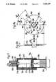
- FIG. 17is a side view in cross-section of a protective housing for part of a probe according to the present invention.
- FIG. 18is a side view of the probe in FIG. 15.
- FIG. 19is a side view of the tip of the probe in FIG. 15 and part of the intra-arterial cannula of FIG. 15.
- FIG. 20ais a side view of an apparatus for producing probes according to the present invention.
- FIG. 20bis a front view of the apparatus of FIG. 20a.
- FIGS. 20cis a view along line A--A of the apparatus of FIG. 20a.
- FIG. 20dis a top view of the apparatus of FIG. 20a.
- FIG. 21is a detailed side view of fiber holders of the apparatus of FIG. 20a.
- FIG. 22is a cross-sectional view of a probe made as shown in FIGS. 21 and 20a.
- FIG. 23is side view of the probe of FIG. 22.
- FIG. 24is side view of the probe of FIG. 22.
- FIG. 25is a cross-sectional view of a probe according to the present invention.
- FIG. 26is a cross-sectional view of two probes according to the present invention.
- FIG. 27is a partial top view of a fiber guide of the apparatus of FIG. 20a.
- FIG. 28is a partial top view of a fiber guide of the apparatus of FIG. 20a.
- an optical fiber 10 of diameter "a"is shown in tension around a mandrel 12, producing a bend 14 in the fiber.
- a radius of the bend 14is approximately equal to the diameter a of the optical fiber 10.
- the particular geometry and configuration of the optical fiber 10is maintained by applying a tip support coating (also referred to as an encapsulant or potting material) 18 around the fiber 10.
- the mandrel 12may be removed by cutting it close to the fiber optic bundle and carefully withdrawing it.
- Another layer of coatingcan be applied to the fiber by dipping or spraying on the appropriate material to seal the hole left by the mandrel.
- An optical gap 20(also referred to as a "sample chamber”) is provided in the fiber 10 for containing and holding a chemical-indicating colorimetric material. Methods for creating such gaps will be discussed below.
- a common radial configurationmay be employed for multiple optical fibers.
- Three optical fibers 30, 31, 32are stacked on top of a three-mandrel stack of mandrels 33, 34 and 35. In this configuration the fibers contact each other and compete for position on the mandrels. Half of each fiber resides slightly recessed within the total cross-section of multi-fiber arrangement. Each fiber is thus disposed so that it is presented for convenient and effective formation of an optical gap sample chamber.
- mandrels 43, 44, and 45are stacked with a common radial pattern as viewed from above (FIG. 4b) but the mandrels are spaced apart by optical fibers 40, 41, and 42 disposed on the mandrels. In this configuration the optical fibers do not bear down directly on each other, particularly where tension is applied.
- a three channel probewas made of the configuration of FIG. 3a using plastic fiber and wire mandrells with 250 micron diameters.
- the resulting probehad a maximum diameter of 1.56 mm.
- Three probeswere made with optical fiber mandrells and optic fibers with 125 micron diameters. These probes had maximum diameters of 630 microns, 800 microns, and 584 microns.
- the maximum diameter of the finished probeis inversely related to the tension applied to the fiber bundle during fabrication.
- optical fibers 50 and 51are supported by a mandrel 53 and a mandrel 54 supports an optical fiber 52 spaced apart from the fibers 50, 51 and the mandrel 53.
- the mandrels 53 and 54may be spaced apart any desired and workable distance.
- the fibers 50, 51, and 52may have different bend radiuses. These radiuses may be varied to produce an arrangement that is of a desired overall shape, e.g. circular or rectangular. These different shapes of the fiber bundle facilitate cutting of the optical gap or they enhance the flow profile of fluids flowing past the sensor in use.
- the optical fibersmay be positioned so that they are not in contact with each other. This provides complete separation of sensor channels and facilitates positioning and removal of mandrels. It is, however, within the scope of this invention to provide such an arrangement in which a fiber does contact an adjacent fiber.
- FIGS. 3a, 4a, and 5aWith respect to the arrangement shown in FIGS. 3a, 4a, and 5a, three fibers are shown. It is within the scope of this invention to employ two or more fibers in such arrangements. Of course using a greater number of fibers will increase the overall size of the resulting multi-fiber sensor.
- an apparatus 150has an upright member 152 to which are secured a top spider 154, a mid-position spider 156 and a vacuum chuck 158. These items may be semipermanently secured to the upright member 152 so that they can be moved and positioned as desired.
- the upright member 152is secured to a top arm 160 and a bottom arm 162 which in turn are pivotally connected to a wall 164 by pivots 166 and 168 respectively.
- the wall 164is mounted on a base 174.
- Radiation from an ultraviolet lamp 170passes through a quartz window 172 in the wall 164 to cure potting encapsulant material applied to a bundle 176 of one or more fibers disposed between the spiders 154, 156 and the vacuum chuck 158.
- the vacuum chuckis movably disposed on the upright member 152 to facilitate the handling of ends of the fibers in the bundle 176 and to provide adjustability of the tension on the fibers.
- a shield 178 movably connected to the wall 164can be moved into position to shield personnel from radiation emitted by the lamp 170.
- An electrostatic charge neutralizer 180 secured to the wall 164eliminates electrostatic charges in the fibers.
- Pulsed intermittent application of the radiation from the u.v. lamp 170can be achieved by alternately turning the lamp on and off or by periodically blocking the beam.
- a shutter 171is disposed so that it may be moved to close off the quartz window 172.
- the shutter 171is shown as connected to a motor 173 which operates to move the shutter 171 toward and away from the quartz window to achieve the desired pulsing of radiation for curing fibers.
- Pulses of 0.75 seconds durationare preferred for preferred potting materials; pulses of longer duration might cause a damaging temperature rise in the fibers.
- a heat shieldcan be placed over the fiber bends on the spider during this curing operation to protect them from heat damage.
- a vacuum chuck 194(like the vacuum chuck 158 of FIG. 6) has a chuck body 196 with a chuck funnel 198 having a concave funnel opening 200 for receiving fiber ends and a funnel bore 202 through which the fiber ends pass into a funnel chamber 204.
- the chuck body 196is movably mounted above a dash pot 206 and comes to rest on a top member 208 of the dash pot 206 which is mounted on a dash pot base 210.
- a ram 212moves into a bottom bore 214 of the funnel bore 202, clamping the fiber ends between the ram and an O-ring 218 in the funnel bore.
- the rodis sealed by a bottom seal 216.
- a vacuumis applied to the chuck by a vacuum pump 217 (FIG. 6) through an opening 219. The vacuum chuck applies minimal tension to the fibers.
- a spider disc 182(used e.g. with the spiders 154 and 156 of the apparatus 150) has six slots 184 and six notches 186 in a middle ridge 188 surrounding a hole 190. Wires 192 passed through these notches and slots and secured to the disc serve to separate optical fibers held therebetween. Dimensions indicated are in inches.
- a probe 50 according to the present invention with coatings and membranes as previously describedis shown containing three optical fibers 51, 52, 53.
- An optical gap sample chamber 54is shown as a five-walled chamber.
- the gapis about 100 microns long and can be, preferably, 85 to 115 microns long. Preferable gap depth ranges between 130 and 160 microns.
- the probe 50is about 700 microns in diameter. It is preferred that this chamber be formed by using an excimer laser because use of such a laser provides precise location, exact dimensions, and an optically clear finish to cut fiber faces 53a and 53b.
- a probe 60has three optical fibers 61, 62, and 63 encapsulated in cured potting material 67.
- Each fiber 61, 62, 63is associated with a sample chamber 64, 65, 66, respectively.
- the distance mis the outside diameter of the fiber optic probe 60 and should be controlled as appropriate for the intended use of the probe. As an example, if the intended use is for insertion through an arterial cannula the outside diameter should be small enough to fit easily through the cannula.
- the distance nis the thickness of encapsulant material lying over a particular fiber. This distance affects the volume of the sample chamber, the separation of the light path from the outside environment, and the outside diameter of the probe.
- the probe 60has been coated (undercoating, overcoating, e.g. as in FIG. 12) and the chambers 64, 65, 66 are like the chambers 70, 80, 90, respectively (FIGS. 12, 13, 14). Membranes have been applied over the chambers 64, 65, 66 as for the chambers 70, 80, 90.
- the longitudinal distance s from chamber 64 to the tip end of the probeis about 2540 microns and preferably is in the range of 2240 to 2840 microns.
- the distance longitudinal t between chambers 64 and 65is 790 microns and is preferably in the range of 915 to 665 microns as is the distance v between the chambers 65 and 66.
- This preferred longitudinal spacingminimizes the depth of intrusion into, e.g. a human blood vessel, yet reduces structural weakness which might be caused by chambers spaced closely together. This spacing also facilitates loading of chemical indicators into gaps as well as the application of membrane material over gaps.
- a pH sample chamber 70 through an optical fiber probe 79 according to the present inventionis shown in FIG. 12.
- the chamber 70has an undercoating 72 (preferably of a water impermeable polymer such as commercially available Petrarch SE, Teflon, or Perylene), to protect the sample chamber from changes in chemical concentration due to the diffusion of water and an overcoating 74 of the same material.
- the undercoating 72may be of multiple layers to increase resistance to water transport; a pH indicating material 76 (e.g. phenyl red, buomocresol green, or other subtalein indicators that react, e.g. change color or fluoresce upon a change in pH) and a selective membrane 78 (e.g. nitro cellulose or porous hydrophilic polymers).
- the membraneselectively permits hydronium ions to flow from outside the probe 79 into the sample chamber 70.
- the coatingsare applied before gaps are formed.
- a carbon dioxide sample chamber 80 according to the present invention through an optical fiber 89has an undercoating 82 (like 72); an overcoating 84 (like 74); a CO 2 indicator 86 (e.g. phynol red combined with bicarbonate or other pH indicator); and a selective membrane 88 which selectively permits CO 2 to pass from outside the fiber 89 into the sample chamber 80.
- the CO 2reacts with water present in the sample chamber to create carbonic acid which in turn reacts to change the color of the pH indicator present in the chamber.
- any pH indicatormay be used to indicate CO by combining the indicator with bicarbonate and isolating the reaction from hydronium ions in the environment while permitting access to CO 2 .
- an oxygen sample chamber 90 through an optical fiber 99has: an undercoating 92; an overcoating 94; and oxygen-indicating colorimetric substance 96 [(e.g. BASF Fluorol Green Gold (perylene dibutyrate)] or other fluorescent chemicals with fluorescent lifetimes such that they are quenched in response to the presence of oxygen; and an oxygen semi-permeable membrane 98 (e.g. silicone rubber or Teflon (TM) material, PTFE, porous polypropylene or porous polycarbonate) which selectively permits oxygen to pass from outside the fiber 99 to the oxygen-indicating substance 96.
- oxygen-indicating colorimetric substance 96e.g. BASF Fluorol Green Gold (perylene dibutyrate)
- an oxygen semi-permeable membrane 98e.g. silicone rubber or Teflon (TM) material, PTFE, porous polypropylene or porous polycarbonate
- phenol red material immobilized on porous glassWith phenol red material immobilized on porous glass, the glass and membrane are supported by a material such as hydroxy propyl cellulose or hydroxyl ethyl cellulose (plus bicarbonate for CO 2 ).
- An immobilizeris used to prevent phenyl red (indicator) from migrating out of the sample chamber.
- the support materialcan be applied manually by mixing it with porous glass.
- Cellulose acetateis applied to the entire tip of a sensor to separate the sample chamber from the exterior environment to insure only the desired analyte comes in and to hold the indicator in the sample chamber.
- a measurement of CO 2 or oxygen concentration accomplished by the probe of FIG. 14can be expressed as a partial pressure of total gas.
- a probe 100(like the probe 60) according to the present invention has a bundle of optical fibers 232 which extend through a connector 232.
- the probe's bundle of fibersis glued into a male luer 234 with adhesive 235.
- the connector 230is made preferably from poly carbonate plastic.
- a protective tube 242preferably made from polyvinylchloride tubing is secured around the male luer 234 and provides strain relief.
- the fiber bundle 232is surrounded by a black inner tube 238, preferably made from polyethylene to provide lubricity in the interior of the tubing to facilitate the passing of fibers therethrough; the black color prevents ambient light from affecting the fibers.
- a protective tube 240surrounds the tube 238.
- the tube 240is made preferably from polyethylene and extends from the connector 230 to a junction box 231 (FIG. 16).
- the tube 242surrounds a portion of the tube 240, as does a tube 244 (like tube 242) adjacent the junction box 231. In one embodiment the distance from the male luer 234 to the junction box is about 12 inches.
- the probe 100has been disposed in an intra-arterial cannula 101. As shown in FIG.
- the probe 100may then be connected to a sensor interface unit 120 (shown as separate from a base unit but which could be incorporated therein) which is connected to a base unit 122.
- the sensor interface unitprovides light input to the probe and detects and measures light coming out of the probe. Signals from the unit 120 are then fed into the base unit where they are processed for display or recordation or both.
- a tip 103 of the probe 100extends into the intra-arterial cannula 101.
- the cannula 101is suitable for introduction into and disposition within a human blood vessel.
- the tip 103is disposable in the cannula (e.g. when the cannula is emplaced in an artery) by connecting the luer y connector 102 to the cannula and then inserting the probe 100 into the cannula through one channel 107 of the luer y connector. It is preferred that the distance k from the end of the cannula to the tip of the probe be such that there is good "washability" or fluid flow over the sample chambers; e.g. in certain preferred embodiments this is about 4910 microns.
- the distance from the end of the cannula to the first adjacent sample chamberbe such that fluid injected through the luer y connector does not diffuse into the blood in the region of the sample chambers producing erroneous readings; e.g. in preferred embodiments this is about 790 microns.
- Whatever fluid was being introduced into or withdrawn from the cannulamay be introduced or withdrawn from a channel 105 of the luer y connector through which the probe 100 does not extend.
- FIGS. 20a-20dillustrate another apparatus 250 for fabricating a multi-fiber probe according to the present invention.
- the apparatus 250has an upright member 252 to which are pivotably connected two arms 254 and 256.
- a weight holder 258is secured to the arm 254 and a weight holder 260 is secured to the arm 256.
- a micro pin mount 262is secured to the top of arm 254 and a micro pin mount 264 is secured to the top of the arm 256.
- a fiber guide 266is secured to a bottom portion of the arm 254 and a fiber guide 268 is secured to a bottom portion of the arm 256.
- the micro pin mount 262has two micro pins, each for independently holding an optical fiber.
- the weight holder 258has two weights, 270 and 272, one each for each of two fibers 274 and 276 supported from the micro pin mount 262.
- the weight holder 260has a weight 278 for a fiber 280 supported from the micro pin mount 264.
- the weights 270, 272 and 278are freely movable up and down on a wire extending through the weights; wire 282 extending through weights 270, 272 and secured to a top arm 284 and a bottom arm 286 of the weight holder 258; and wire 288 extending through the weight 278 and secured to a top arm 290 and a bottom arm 292 of the weight holder 260.
- Each weighthas a sheet magnet 294 secured thereto. Fibers are clamped between the fixed magnets 294 and a free sheet magnet 296 which provides a sufficient clamping effect to hold the fibers and hang the weights from them to provide the desired tension.
- Each weightweighs about 18 grams.
- Notchesare provided in the fiber guides 266, 268 and in a top shoulder 298 (e.g. FIG. 20c) of each weight so that the fibers are held separately and independently in the apparatus 250.
- the fiber guide 68(shown partially) has a recess 269 for receiving and holding the fiber ends of the fiber 280.
- the fiber guide 266(shown partially in FIG. 28) has a recess 267 for receiving and holding the fiber ends of fibers 274 and 276. (Dimensions in FIGS. 26, 27 are in inches). This insures formation of a probe of desired configuration.
- Three pairs of vacuum tubes 300, 302, 304receive and hold the ends of each of the fibers 274, 276, and 280 respectively. Each tube receives and holds one fiber end. By thus holding the fiber ends, the use of the apparatus and handling of the fibers is facilitated and some minimal tension is applied to the fibers.
- the arms 254 and 256are pivotable with respect to the upright member 252 one or more fibers can easily be emplaced on each arm's micro hooks prior to closing of the arms. Closing the arms into proximity with each other moves the fibers into a desired relationship with each other so that an ultimate configuration and size for a multi-fiber probe is achieved.
- Potting encapsulant materiale.g. commercially available ELC 4481 of Electro-Lite Corp.
- ELC 4481 of Electro-Lite Corp.can be applied manually to the exposed portion of the fibers between the top portions and bottom portions of the arms 254 and 256.
- a lampmay be used with the apparatus 250 for curing the potting encapsulant material.
- the potted cured fibersare removed from the apparatus. Potting material is applied to the tip of the assembly--the portions hanging over the micro hooks including the fiber bends. This material is cured. Thus the fiber bends and a portion of the fibers adjacent the fiber bends is covered with cured potting material and the fibers (and thermocouple or other device) in these portions are not in contact.
- the harness(tubing, connector, junction box) is assembled and then gaps are formed in the fibers. Coatings are applied; indicators are emplaced in the gaps; and membranes are applied over the gaps by placing membrane material dissolved in a suitable solvent over the gaps (sample chambers); e.g.
- cellulose acetate in acetone as a membrane over a pH indicatorpolydimethyl siloxane in methylene chloride as a membrane over a CO 2 or O 2 chamber or polycarbonate in chloroform.
- the resulting assemblyis a multi-fiber device useful in an optical sensor probe.
- FIG. 21shows the fiber holders 266, 268 in more detail. These holders are configured so that the fibers to be worked with and treated hang independently of each other.
- Fiber holder 266has a cantilevered pin 310 from which hangs a thermocouple 312 [not shown in FIGS. 20a, b] and a cantilever pin 314 from which hangs a fiber 316. The pins are preferably disposed at an angle to maintain the fibers thereon.
- Fiber holder 268has a cantilevered pin 318 from which hangs a fiber 320 and cantilevered pin 322 from which hangs a fiber 324.
- the pins 310, 314 and 318are emplaced in grooves that are about 5 mils wide.
- the pin 322is emplaced in a groove that is about 13 mils wide.
- a fiber hanging over pin 322hangs with its ends spaced further apart that the ends of a fiber hanging over one of the other pins.
- FIGS. 22, 23 and 24show a probe 332 (like the probe 60 previously described regarding sample chambers, coatings, and membranes) corresponding to the fabrication layout of FIG. 21.
- Dimensions given in FIGS. 22 and 23are in inches.
- the distance between the strands of the thermocouple fiberis 0.005 inches.
- the size of sample chambers 326, 328 and 330may preferably range in width between about 130 to about 160 microns with 145 microns preferred.
- the overall diameter of the probe 332 as shownis 650 microns (0.0256 inches) this diameter preferably ranges from about 600 microns to about 730 microns with preferred diameter being 650 microns.
- thermocouple 312has a small (e.g. 10 mil) metal bead 325 to which are connected two 2 mil diameter metal leads 327.
- Commercially available Type E thermocouplescan be used or a thermister. As shown in FIG.
- the length from line P (line P represents the extent of the potting material applied to the probe tip) to the exterior of the first fiber bendsis about 0.026 inches.
- a preferable range for this distanceis 0.020 to 0.031 inches.
- the distance from point P to the thermocoupleis about 0.044 inches (and ranges preferably between 0.040 and 0.051 inches).
- the distance from point P to the end of fiber 324is shown as about 0.070 inches (preferably ranging between 0.066 and 0.075 inches).
- the thermocoupleis located preferably interiorly of all the fibers because it needs no tangentical access to fluids and it can occupy interior space not occupied by optical fibers.
- FIG. 25illustrates a probe 334 in which all fiber bends (of fibers 336, 338 and 340) are of substantially the same diameter.
- a thermocouple 342is present in the center of the probe 344.
- FIG. 26presents a fiber probe 346 produced with apparatus 150, 160 using a spider as shown in FIG. 4a. Since the fibers in the apparatus 150 contact and compete with each other for position, the generally triangular disposition achieved requires more potting encapsulant to effect a desired thickness of encapsulating material over the fibers. In this sense a circular configuration of the fibers of probe (e.g. as shown in FIG. 10) is more efficient.
- one preferred method for forming an optical probe with a plurality (one or more) of optical fiber sensorsincludes the steps of: racking the fibers, i.e., emplacing them over hooks, a spider, or other suspension device producing bends in them; applying tension to the fibers, together or individually; applying potting material and curing it, in some embodiments first to the portion adjacent the bends and then to the bends themselves; introducing the fibers into a harness (connectors, tubing, junction boxes, etc.); forming gaps in the fibers; coating the fibers and gaps; introducing indicators into the gaps; and applying selective membranes over the gaps.
- a gapcan be formed by using two fibers, bending one, and positioning the second fiber near the first to form the gap.
Landscapes
- Physics & Mathematics (AREA)
- General Physics & Mathematics (AREA)
- Optics & Photonics (AREA)
- Chemical & Material Sciences (AREA)
- Immunology (AREA)
- Plasma & Fusion (AREA)
- Health & Medical Sciences (AREA)
- Life Sciences & Earth Sciences (AREA)
- Analytical Chemistry (AREA)
- Biochemistry (AREA)
- General Health & Medical Sciences (AREA)
- Engineering & Computer Science (AREA)
- Pathology (AREA)
- Chemical Kinetics & Catalysis (AREA)
- Investigating Or Analysing Materials By Optical Means (AREA)
- Investigating Or Analysing Materials By The Use Of Chemical Reactions (AREA)
- Investigating Or Analyzing Materials By The Use Of Ultrasonic Waves (AREA)
- Optical Head (AREA)
- Optical Fibers, Optical Fiber Cores, And Optical Fiber Bundles (AREA)
- Measurement Of The Respiration, Hearing Ability, Form, And Blood Characteristics Of Living Organisms (AREA)
- Other Investigation Or Analysis Of Materials By Electrical Means (AREA)
- External Artificial Organs (AREA)
- Manufacture, Treatment Of Glass Fibers (AREA)
- Laser Surgery Devices (AREA)
- Optical Couplings Of Light Guides (AREA)
Abstract
Description
Claims (28)
Priority Applications (12)
| Application Number | Priority Date | Filing Date | Title |
|---|---|---|---|
| US07/526,822US5124130A (en) | 1990-05-22 | 1990-05-22 | Optical probe |
| PCT/EP1991/000934WO1991018306A2 (en) | 1990-05-22 | 1991-05-22 | Optical probe |
| CA002083389ACA2083389A1 (en) | 1990-05-22 | 1991-05-22 | Optical probe |
| DE69112210TDE69112210D1 (en) | 1990-05-22 | 1991-05-22 | OPTICAL PROBE. |
| FI925289AFI925289A0 (en) | 1990-05-22 | 1991-05-22 | OPTISK SOND |
| JP91509714AJPH05506949A (en) | 1990-05-22 | 1991-05-22 | optical probe |
| AT91909821TATE126606T1 (en) | 1990-05-22 | 1991-05-22 | OPTICAL PROBE. |
| AU78896/91AAU645323B2 (en) | 1990-05-22 | 1991-05-22 | Optical probe |
| BR919106495ABR9106495A (en) | 1990-05-22 | 1991-05-22 | PROCESS AND APPARATUS FOR THE MANUFACTURE OF A BEAM OF OPTICAL FIBERS, OPTICAL PROBE AND PROCESS FOR THE MANUFACTURE OF THE SAME AND SUBJECTION DEVICE FOR RECEIVING AND RETENTING END OF OPTICAL FIBERS |
| EP91909821AEP0530262B1 (en) | 1990-05-22 | 1991-05-22 | Optical probe |
| US07/810,479US5397411A (en) | 1990-05-22 | 1991-12-19 | Method for making optical probe |
| NO92924487ANO924487L (en) | 1990-05-22 | 1992-11-20 | OPTICAL PROBLEM |
Applications Claiming Priority (1)
| Application Number | Priority Date | Filing Date | Title |
|---|---|---|---|
| US07/526,822US5124130A (en) | 1990-05-22 | 1990-05-22 | Optical probe |
Related Child Applications (1)
| Application Number | Title | Priority Date | Filing Date |
|---|---|---|---|
| US07/810,479DivisionUS5397411A (en) | 1990-05-22 | 1991-12-19 | Method for making optical probe |
Publications (1)
| Publication Number | Publication Date |
|---|---|
| US5124130Atrue US5124130A (en) | 1992-06-23 |
Family
ID=24098939
Family Applications (2)
| Application Number | Title | Priority Date | Filing Date |
|---|---|---|---|
| US07/526,822Expired - LifetimeUS5124130A (en) | 1990-05-22 | 1990-05-22 | Optical probe |
| US07/810,479Expired - LifetimeUS5397411A (en) | 1990-05-22 | 1991-12-19 | Method for making optical probe |
Family Applications After (1)
| Application Number | Title | Priority Date | Filing Date |
|---|---|---|---|
| US07/810,479Expired - LifetimeUS5397411A (en) | 1990-05-22 | 1991-12-19 | Method for making optical probe |
Country Status (10)
| Country | Link |
|---|---|
| US (2) | US5124130A (en) |
| EP (1) | EP0530262B1 (en) |
| JP (1) | JPH05506949A (en) |
| AT (1) | ATE126606T1 (en) |
| AU (1) | AU645323B2 (en) |
| BR (1) | BR9106495A (en) |
| CA (1) | CA2083389A1 (en) |
| DE (1) | DE69112210D1 (en) |
| FI (1) | FI925289A0 (en) |
| WO (1) | WO1991018306A2 (en) |
Cited By (30)
| Publication number | Priority date | Publication date | Assignee | Title |
|---|---|---|---|---|
| US5308771A (en)* | 1992-04-13 | 1994-05-03 | Geo-Centers, Inc. | Chemical sensors |
| US5326542A (en)* | 1992-10-01 | 1994-07-05 | Tetra Laval Holdings & Finance S.A. | Method and apparatus for sterilizing cartons |
| US5335305A (en)* | 1991-12-19 | 1994-08-02 | Optex Biomedical, Inc. | Optical sensor for fluid parameters |
| US5342190A (en)* | 1992-07-22 | 1994-08-30 | Optex Biomedical, Inc. | Apparatus for emplacing viscous material in a cavity |
| US5358876A (en)* | 1991-07-17 | 1994-10-25 | Mitsubishi Gas Chemical Company, Inc. | Oxygen indicator |
| US5408999A (en)* | 1992-10-23 | 1995-04-25 | Optex Biomedical, Inc. | Fiber-optic probe for the measurement of fluid parameters |
| US5448071A (en)* | 1993-04-16 | 1995-09-05 | Bruce W. McCaul | Gas spectroscopy |
| US5500768A (en)* | 1993-04-16 | 1996-03-19 | Bruce McCaul | Laser diode/lens assembly |
| US5615052A (en)* | 1993-04-16 | 1997-03-25 | Bruce W. McCaul | Laser diode/lens assembly |
| US5625189A (en)* | 1993-04-16 | 1997-04-29 | Bruce W. McCaul | Gas spectroscopy |
| US5740291A (en)* | 1995-10-13 | 1998-04-14 | The University Of Western Ontario | Fiber optic sensor for sensing particle movement in a catalytic reactor |
| US20030231818A1 (en)* | 2002-02-20 | 2003-12-18 | Institut National D'optique | Packaged optical sensors on the side of optical fibres |
| US7025734B1 (en) | 2001-09-28 | 2006-04-11 | Advanced Cardiovascular Systmes, Inc. | Guidewire with chemical sensing capabilities |
| US7039454B1 (en)* | 1999-03-29 | 2006-05-02 | Hitachi Medical Corporation | Biological optical measuring instrument |
| US20070201031A1 (en)* | 2006-02-28 | 2007-08-30 | Physical Logic Ag | Optical Blood Pressure and Velocity Sensor |
| US20070203414A1 (en)* | 2006-02-21 | 2007-08-30 | Physical Logic Ag | Optical Sensing Catheter System |
| US20070292940A1 (en)* | 2004-08-16 | 2007-12-20 | Marcel Roll | Bioreactor |
| US20090155770A1 (en)* | 2007-12-12 | 2009-06-18 | Kimberly-Clark Worldwide, Inc. | Implantable devices for fiber optic based detection of nosocomial infection |
| US20090247899A1 (en)* | 2006-02-23 | 2009-10-01 | Christopher Raymond Dennison | Pressure sensor for biological fluids and use thereof |
| US8694069B1 (en) | 2009-12-21 | 2014-04-08 | Kosense, LLC | Fiber-optic probe with embedded peripheral sensors for in-situ continuous monitoring |
| US8805128B2 (en) | 2010-03-30 | 2014-08-12 | Uvic Industry Partnerships Inc. | Multi-point pressure sensor and uses thereof |
| US20140266266A1 (en)* | 2013-03-12 | 2014-09-18 | Dionex Softron Gmbh | Flow cell |
| US20170273565A1 (en)* | 2016-03-28 | 2017-09-28 | Becton, Dickinson And Company | Optical fiber sensor |
| US9956651B2 (en) | 2013-03-12 | 2018-05-01 | Dionex Softron Gmbh | Method for producing a fluidic connection component for chromatography |
| US10175254B2 (en) | 2013-07-16 | 2019-01-08 | Palo Alto Health Sciences, Inc. | Methods and systems for quantitative colorimetric capnometry |
| WO2019229201A1 (en)* | 2018-05-29 | 2019-12-05 | Ge Healthcare Bio-Sciences Ab | Optical flow cell |
| US10610085B2 (en) | 2009-10-23 | 2020-04-07 | Koninklijke Philips N.V. | Optical sensing-enabled interventional instruments for rapid distributed measurements of biophysical parameters |
| US10835718B2 (en) | 2016-03-28 | 2020-11-17 | Becton, Dickinson And Company | Cannula with light-emitting optical fiber |
| US10850046B2 (en) | 2016-03-28 | 2020-12-01 | Becton, Dickinson And Company | Cannula locator device |
| US12066375B2 (en) | 2016-11-30 | 2024-08-20 | Cytiva Sweden Ab | Optical flow cell |
Families Citing this family (5)
| Publication number | Priority date | Publication date | Assignee | Title |
|---|---|---|---|---|
| US5271398A (en)* | 1991-10-09 | 1993-12-21 | Optex Biomedical, Inc. | Intra-vessel measurement of blood parameters |
| WO2002011961A1 (en)* | 2000-08-09 | 2002-02-14 | Chiral Photonics, Inc. | Apparatus and method for manufacturing fiber gratings |
| US20040101267A1 (en)* | 2002-11-27 | 2004-05-27 | Itt Manufacturing Enterprises, Inc. | Optic fiber attenuator |
| US7775375B2 (en)* | 2005-11-03 | 2010-08-17 | Medica S.R.L. | Redundant ultrafiltration device |
| WO2009091920A1 (en)* | 2008-01-15 | 2009-07-23 | Taro Nicholas L | Method and apparatus for determining a deterioration of respiratory function |
Citations (58)
| Publication number | Priority date | Publication date | Assignee | Title |
|---|---|---|---|---|
| US3068742A (en)* | 1959-06-15 | 1962-12-18 | American Optical Corp | Means for performing colorimetry |
| US3123066A (en)* | 1964-03-03 | brumley | ||
| US3734691A (en)* | 1971-09-15 | 1973-05-22 | Ford Motor Co | Sensing system for a chemiluminescent instrument |
| US3754867A (en)* | 1970-12-11 | 1973-08-28 | Bjorksten Res Lab Inc | Carbon dioxide sensing system |
| US3814081A (en)* | 1971-04-02 | 1974-06-04 | Olympus Optical Co | Optical measuring catheter |
| US3822695A (en)* | 1971-12-29 | 1974-07-09 | Olympus Optical Co | Catheter system |
| US3830222A (en)* | 1972-07-07 | 1974-08-20 | Johnson Res Foundation | Method and apparatus for observing rates of reaction of oxygen in living tissues |
| US3905767A (en)* | 1974-01-30 | 1975-09-16 | Miles Lab | Process for qualitative analysis or quantitation of antigens or antibodies |
| US3992158A (en)* | 1973-08-16 | 1976-11-16 | Eastman Kodak Company | Integral analytical element |
| US4003707A (en)* | 1975-02-28 | 1977-01-18 | Max-Planck-Gesellschaft Zur Forderung Der Wissenschaften E.V. | Method and arrangement for measuring the concentration of gases |
| US4041932A (en)* | 1975-02-06 | 1977-08-16 | Fostick Moshe A | Method for monitoring blood gas tension and pH from outside the body |
| US4050898A (en)* | 1976-04-26 | 1977-09-27 | Eastman Kodak Company | Integral analytical element |
| US4115067A (en)* | 1975-09-29 | 1978-09-19 | Combustion Equipment Associates Inc. | Pollution monitoring apparatus |
| GB1525989A (en)* | 1975-07-09 | 1978-09-27 | Commissariat Energie Atomique | Device for analysing a solution |
| US4119406A (en)* | 1976-05-06 | 1978-10-10 | Miles Laboratories, Inc. | Calibration apparatus |
| US4125372A (en)* | 1975-04-01 | 1978-11-14 | Kabushiki Kaisha Kyoto Kaiichi Kagaku | Method and device for testing liquids |
| US4200110A (en)* | 1977-11-28 | 1980-04-29 | United States Of America | Fiber optic pH probe |
| US4201222A (en)* | 1977-08-31 | 1980-05-06 | Thomas Haase | Method and apparatus for in vivo measurement of blood gas partial pressures, blood pressure and blood pulse |
| JPS56124036A (en)* | 1981-01-26 | 1981-09-29 | Sumitomo Electric Ind Ltd | Spectroanalytic device for diagnosis of morbidity |
| US4306877A (en)* | 1978-07-29 | 1981-12-22 | Max-Planck-Gesellschaft Zur Forderung Der Wissenschaften E.V. | Optical measurement of concentration |
| US4344438A (en)* | 1978-08-02 | 1982-08-17 | The United States Of America As Represented By The Department Of Health, Education And Welfare | Optical sensor of plasma constituents |
| US4369364A (en)* | 1978-12-27 | 1983-01-18 | Bbc Brown, Boveri & Company Limited | Monitoring device with an optical sensor for the detection of interference arcs in electrical systems |
| EP0073558A2 (en)* | 1981-08-25 | 1983-03-09 | THE UNITED STATES OF AMERICA as represented by the Secretary United States Department of Commerce | Fiber optic pH probe for tissue measurements |
| US4413628A (en)* | 1980-11-19 | 1983-11-08 | Tamulis Walter G | pH Monitor electrode electrolyte cartridge |
| JPS59154340A (en)* | 1983-02-23 | 1984-09-03 | Mitsubishi Heavy Ind Ltd | Wetness measuring device |
| US4474183A (en)* | 1983-01-17 | 1984-10-02 | Kuraray Co., Ltd. | Gas sensor |
| US4476870A (en)* | 1982-03-30 | 1984-10-16 | The United States Of America As Represented By The Department Of Health And Human Services | Fiber optic PO.sbsb.2 probe |
| EP0126600A2 (en)* | 1983-05-17 | 1984-11-28 | Elf U.K. Plc | Optical fibre probe |
| US4497577A (en)* | 1981-06-03 | 1985-02-05 | Hitachi, Ltd. | Steam wetness measuring apparatus |
| US4535786A (en)* | 1983-07-25 | 1985-08-20 | Kater John A R | Measurement of body fluid chemistry |
| US4599901A (en)* | 1982-09-30 | 1986-07-15 | University Of California | Pressure-sensitive optrode |
| US4622974A (en)* | 1984-03-07 | 1986-11-18 | University Of Tennessee Research Corporation | Apparatus and method for in-vivo measurements of chemical concentrations |
| US4682895A (en)* | 1985-08-06 | 1987-07-28 | Texas A&M University | Fiber optic probe for quantification of colorimetric reactions |
| US4684245A (en)* | 1985-10-28 | 1987-08-04 | Oximetrix, Inc. | Electro-optical coupler for catheter oximeter |
| US4697593A (en)* | 1984-06-26 | 1987-10-06 | Evans John M | Method and apparatus for measuring blood oxygen levels |
| US4706677A (en)* | 1985-09-23 | 1987-11-17 | Spectramed, Inc. | Multiple sensor bundle |
| US4737343A (en)* | 1986-01-21 | 1988-04-12 | The Regents Of The University Of California | Gas-sensing optrode |
| US4752115A (en)* | 1985-02-07 | 1988-06-21 | Spectramed, Inc. | Optical sensor for monitoring the partial pressure of oxygen |
| US4776340A (en)* | 1987-03-23 | 1988-10-11 | Spectramed, Inc. | Hematocrit measurement by differential optical geometry in a short-term diagnostic cardiovascular catheter, and application to correction of blood-oxygen measurement |
| US4785814A (en)* | 1987-08-11 | 1988-11-22 | Cordis Corporation | Optical probe for measuring pH and oxygen in blood and employing a composite membrane |
| US4796633A (en)* | 1985-06-25 | 1989-01-10 | American Hospital Supply Corporation | Method and apparatus for in vitro calibration of oxygen saturation monitor |
| US4800886A (en)* | 1986-07-14 | 1989-01-31 | C. R. Bard, Inc. | Sensor for measuring the concentration of a gaseous component in a fluid by absorption |
| US4803049A (en)* | 1984-12-12 | 1989-02-07 | The Regents Of The University Of California | pH-sensitive optrode |
| US4823167A (en)* | 1986-12-16 | 1989-04-18 | Baxter International Inc. | Catheter calibration device |
| US4830013A (en)* | 1987-01-30 | 1989-05-16 | Minnesota Mining And Manufacturing Co. | Intravascular blood parameter measurement system |
| US4833091A (en)* | 1987-02-06 | 1989-05-23 | Shiley Incorporated | Sensor system |
| US4834532A (en)* | 1986-12-05 | 1989-05-30 | The State Of Oregon Acting By And Through The State Board Of Higher Education On Behalf Of Oregon Health Sciences University | Devices and procedures for in vitro calibration of pulse oximetry monitors |
| US4854321A (en)* | 1986-06-18 | 1989-08-08 | Medex, Inc. | Integrated optic system for monitoring blood gases |
| EP0352610A2 (en)* | 1988-07-25 | 1990-01-31 | Abbott Laboratories | Fiber-optic physiological probes |
| US4906249A (en)* | 1989-02-23 | 1990-03-06 | Medtronic, Inc. | Terpolymer composition with bound indicator dye for fiber optic probe |
| US4930506A (en)* | 1986-11-17 | 1990-06-05 | Hellige Gmbh | Combined sensor for the transcutaneous measurement of oxygen and carbon dioxide in the blood |
| US4974592A (en)* | 1988-11-14 | 1990-12-04 | American Sensor Systems Corporation | Continuous on-line blood monitoring system |
| US4981355A (en)* | 1989-05-12 | 1991-01-01 | Baxter International Inc. | Calibration cup for in vitro calibration of an oxygen saturation monitor and method of using same |
| US4989606A (en)* | 1987-01-30 | 1991-02-05 | Minnesota Mining And Manufactoring Company | Intravascular blood gas sensing system |
| US4991590A (en)* | 1989-01-30 | 1991-02-12 | Martin Goffman Associates | Fiber optic intravascular blood pressure transducer |
| US5005576A (en)* | 1988-04-09 | 1991-04-09 | Hewlett-Packard Company | Optical probe |
| US5007704A (en)* | 1983-10-28 | 1991-04-16 | Baxter International Inc. | Oximeter |
| US5012809A (en)* | 1986-10-10 | 1991-05-07 | Shulze John E | Fiber optic catheter system with fluorometric sensor and integral flexure compensation |
Family Cites Families (30)
| Publication number | Priority date | Publication date | Assignee | Title |
|---|---|---|---|---|
| US3674013A (en)* | 1970-09-30 | 1972-07-04 | American Optical Corp | Fiberoptic catheter |
| FR2227888B2 (en)* | 1972-07-26 | 1976-04-23 | Rhone Poulenc Ind | |
| JPS6034750B2 (en)* | 1977-03-10 | 1985-08-10 | 株式会社リコー | Developer remaining amount detection device |
| US4430566A (en)* | 1981-04-21 | 1984-02-07 | Vibrac Corporation | Electro-optical angular displacement |
| SE450862B (en)* | 1981-09-04 | 1987-08-03 | Asea Ab | LIGHT BAG DETECTION |
| EP0108527A3 (en)* | 1982-11-03 | 1984-12-27 | Indiana University Foundation | Remote optic atmosphere monitor and method for determining a foreign substance in a fluid |
| US4609871A (en)* | 1984-07-02 | 1986-09-02 | The United States Of America As Represented By The Secretary Of The Navy | Temperature compensated optical fiber interferometric magnetometer |
| US4669467A (en)* | 1985-03-22 | 1987-06-02 | Massachusetts Institute Of Technology | Mode mixer for a laser catheter |
| US4648892A (en)* | 1985-03-22 | 1987-03-10 | Massachusetts Institute Of Technology | Method for making optical shield for a laser catheter |
| US4758298A (en)* | 1985-09-23 | 1988-07-19 | Spectramed, Inc. | Method for forming multiple sensor bundle |
| US4919891A (en)* | 1986-04-18 | 1990-04-24 | Minnesota Mining And Manufacturing Company | Sensor with overcoating and process for making same |
| US4824789B1 (en)* | 1986-10-10 | 1996-08-13 | Minnesota Mining & Mfg | Gas sensor |
| US5006314A (en)* | 1986-04-18 | 1991-04-09 | Minnesota Mining And Manufacturing Company | Sensor and method for sensing the concentration of a component in a medium |
| US4798738A (en)* | 1986-10-10 | 1989-01-17 | Cardiovascular Devices, Inc. | Micro sensor |
| US4727730A (en)* | 1986-07-10 | 1988-03-01 | Medex, Inc. | Integrated optic system for monitoring blood pressure |
| EP0296180A1 (en)* | 1986-09-22 | 1988-12-28 | Schering Aktiengesellschaft | Injection device |
| US4974929A (en)* | 1987-09-22 | 1990-12-04 | Baxter International, Inc. | Fiber optical probe connector for physiologic measurement devices |
| US4797549A (en)* | 1987-11-09 | 1989-01-10 | General Motors Corporation | Optical sensor and method of making same |
| US5000901A (en)* | 1988-07-25 | 1991-03-19 | Abbott Laboratories | Fiber-optic physiological probes |
| US4907857A (en)* | 1988-07-25 | 1990-03-13 | Abbott Laboratories | Optical fiber distribution system for an optical fiber sensor |
| JP3073994B2 (en)* | 1988-08-11 | 2000-08-07 | 株式会社モリタ製作所 | Variable irradiation angle laser irradiation device |
| US4889407A (en)* | 1988-12-02 | 1989-12-26 | Biomedical Sensors Limited | Optical waveguide sensor and method of making same |
| EP0452421B1 (en)* | 1989-01-04 | 1997-10-08 | Zellweger Uster, Inc. | Fiber testing method |
| US5009655A (en)* | 1989-05-24 | 1991-04-23 | C. R. Bard, Inc. | Hot tip device with optical diagnostic capability |
| US5132057A (en)* | 1989-10-11 | 1992-07-21 | Medex, Inc. | Method of making an optical fiber probe |
| US5044723A (en)* | 1990-04-05 | 1991-09-03 | Alberta Telecommunications Research Centre | Tapered fibre sensor |
| US5166990A (en)* | 1990-08-10 | 1992-11-24 | Puritan-Bennett Corporation | Multiple optical fiber event sensor and method of manufacture |
| US5061857A (en)* | 1990-11-09 | 1991-10-29 | The United States Of America As Represented By The Secretary Of The Navy | Waveguide-binding sensor for use with assays |
| US5169568A (en)* | 1990-12-21 | 1992-12-08 | Ainger Iii Raymond | Method for casting a housing around an endoscope frame |
| US5159654A (en)* | 1991-10-25 | 1992-10-27 | Optex Biomedical, Inc. | Multi-channel optical fiber connector |
- 1990
- 1990-05-22USUS07/526,822patent/US5124130A/ennot_activeExpired - Lifetime
- 1991
- 1991-05-22BRBR919106495Apatent/BR9106495A/enunknown
- 1991-05-22FIFI925289Apatent/FI925289A0/ennot_activeApplication Discontinuation
- 1991-05-22EPEP91909821Apatent/EP0530262B1/ennot_activeExpired - Lifetime
- 1991-05-22JPJP91509714Apatent/JPH05506949A/enactivePending
- 1991-05-22AUAU78896/91Apatent/AU645323B2/ennot_activeCeased
- 1991-05-22ATAT91909821Tpatent/ATE126606T1/ennot_activeIP Right Cessation
- 1991-05-22WOPCT/EP1991/000934patent/WO1991018306A2/enactiveIP Right Grant
- 1991-05-22DEDE69112210Tpatent/DE69112210D1/ennot_activeExpired - Lifetime
- 1991-05-22CACA002083389Apatent/CA2083389A1/ennot_activeAbandoned
- 1991-12-19USUS07/810,479patent/US5397411A/ennot_activeExpired - Lifetime
Patent Citations (58)
| Publication number | Priority date | Publication date | Assignee | Title |
|---|---|---|---|---|
| US3123066A (en)* | 1964-03-03 | brumley | ||
| US3068742A (en)* | 1959-06-15 | 1962-12-18 | American Optical Corp | Means for performing colorimetry |
| US3754867A (en)* | 1970-12-11 | 1973-08-28 | Bjorksten Res Lab Inc | Carbon dioxide sensing system |
| US3814081A (en)* | 1971-04-02 | 1974-06-04 | Olympus Optical Co | Optical measuring catheter |
| US3734691A (en)* | 1971-09-15 | 1973-05-22 | Ford Motor Co | Sensing system for a chemiluminescent instrument |
| US3822695A (en)* | 1971-12-29 | 1974-07-09 | Olympus Optical Co | Catheter system |
| US3830222A (en)* | 1972-07-07 | 1974-08-20 | Johnson Res Foundation | Method and apparatus for observing rates of reaction of oxygen in living tissues |
| US3992158A (en)* | 1973-08-16 | 1976-11-16 | Eastman Kodak Company | Integral analytical element |
| US3905767A (en)* | 1974-01-30 | 1975-09-16 | Miles Lab | Process for qualitative analysis or quantitation of antigens or antibodies |
| US4041932A (en)* | 1975-02-06 | 1977-08-16 | Fostick Moshe A | Method for monitoring blood gas tension and pH from outside the body |
| US4003707A (en)* | 1975-02-28 | 1977-01-18 | Max-Planck-Gesellschaft Zur Forderung Der Wissenschaften E.V. | Method and arrangement for measuring the concentration of gases |
| US4125372A (en)* | 1975-04-01 | 1978-11-14 | Kabushiki Kaisha Kyoto Kaiichi Kagaku | Method and device for testing liquids |
| GB1525989A (en)* | 1975-07-09 | 1978-09-27 | Commissariat Energie Atomique | Device for analysing a solution |
| US4115067A (en)* | 1975-09-29 | 1978-09-19 | Combustion Equipment Associates Inc. | Pollution monitoring apparatus |
| US4050898A (en)* | 1976-04-26 | 1977-09-27 | Eastman Kodak Company | Integral analytical element |
| US4119406A (en)* | 1976-05-06 | 1978-10-10 | Miles Laboratories, Inc. | Calibration apparatus |
| US4201222A (en)* | 1977-08-31 | 1980-05-06 | Thomas Haase | Method and apparatus for in vivo measurement of blood gas partial pressures, blood pressure and blood pulse |
| US4200110A (en)* | 1977-11-28 | 1980-04-29 | United States Of America | Fiber optic pH probe |
| US4306877A (en)* | 1978-07-29 | 1981-12-22 | Max-Planck-Gesellschaft Zur Forderung Der Wissenschaften E.V. | Optical measurement of concentration |
| US4344438A (en)* | 1978-08-02 | 1982-08-17 | The United States Of America As Represented By The Department Of Health, Education And Welfare | Optical sensor of plasma constituents |
| US4369364A (en)* | 1978-12-27 | 1983-01-18 | Bbc Brown, Boveri & Company Limited | Monitoring device with an optical sensor for the detection of interference arcs in electrical systems |
| US4413628A (en)* | 1980-11-19 | 1983-11-08 | Tamulis Walter G | pH Monitor electrode electrolyte cartridge |
| JPS56124036A (en)* | 1981-01-26 | 1981-09-29 | Sumitomo Electric Ind Ltd | Spectroanalytic device for diagnosis of morbidity |
| US4497577A (en)* | 1981-06-03 | 1985-02-05 | Hitachi, Ltd. | Steam wetness measuring apparatus |
| EP0073558A2 (en)* | 1981-08-25 | 1983-03-09 | THE UNITED STATES OF AMERICA as represented by the Secretary United States Department of Commerce | Fiber optic pH probe for tissue measurements |
| US4476870A (en)* | 1982-03-30 | 1984-10-16 | The United States Of America As Represented By The Department Of Health And Human Services | Fiber optic PO.sbsb.2 probe |
| US4599901A (en)* | 1982-09-30 | 1986-07-15 | University Of California | Pressure-sensitive optrode |
| US4474183A (en)* | 1983-01-17 | 1984-10-02 | Kuraray Co., Ltd. | Gas sensor |
| JPS59154340A (en)* | 1983-02-23 | 1984-09-03 | Mitsubishi Heavy Ind Ltd | Wetness measuring device |
| EP0126600A2 (en)* | 1983-05-17 | 1984-11-28 | Elf U.K. Plc | Optical fibre probe |
| US4535786A (en)* | 1983-07-25 | 1985-08-20 | Kater John A R | Measurement of body fluid chemistry |
| US5007704A (en)* | 1983-10-28 | 1991-04-16 | Baxter International Inc. | Oximeter |
| US4622974A (en)* | 1984-03-07 | 1986-11-18 | University Of Tennessee Research Corporation | Apparatus and method for in-vivo measurements of chemical concentrations |
| US4697593A (en)* | 1984-06-26 | 1987-10-06 | Evans John M | Method and apparatus for measuring blood oxygen levels |
| US4803049A (en)* | 1984-12-12 | 1989-02-07 | The Regents Of The University Of California | pH-sensitive optrode |
| US4752115A (en)* | 1985-02-07 | 1988-06-21 | Spectramed, Inc. | Optical sensor for monitoring the partial pressure of oxygen |
| US4796633A (en)* | 1985-06-25 | 1989-01-10 | American Hospital Supply Corporation | Method and apparatus for in vitro calibration of oxygen saturation monitor |
| US4682895A (en)* | 1985-08-06 | 1987-07-28 | Texas A&M University | Fiber optic probe for quantification of colorimetric reactions |
| US4706677A (en)* | 1985-09-23 | 1987-11-17 | Spectramed, Inc. | Multiple sensor bundle |
| US4684245A (en)* | 1985-10-28 | 1987-08-04 | Oximetrix, Inc. | Electro-optical coupler for catheter oximeter |
| US4737343A (en)* | 1986-01-21 | 1988-04-12 | The Regents Of The University Of California | Gas-sensing optrode |
| US4854321A (en)* | 1986-06-18 | 1989-08-08 | Medex, Inc. | Integrated optic system for monitoring blood gases |
| US4800886A (en)* | 1986-07-14 | 1989-01-31 | C. R. Bard, Inc. | Sensor for measuring the concentration of a gaseous component in a fluid by absorption |
| US5012809A (en)* | 1986-10-10 | 1991-05-07 | Shulze John E | Fiber optic catheter system with fluorometric sensor and integral flexure compensation |
| US4930506A (en)* | 1986-11-17 | 1990-06-05 | Hellige Gmbh | Combined sensor for the transcutaneous measurement of oxygen and carbon dioxide in the blood |
| US4834532A (en)* | 1986-12-05 | 1989-05-30 | The State Of Oregon Acting By And Through The State Board Of Higher Education On Behalf Of Oregon Health Sciences University | Devices and procedures for in vitro calibration of pulse oximetry monitors |
| US4823167A (en)* | 1986-12-16 | 1989-04-18 | Baxter International Inc. | Catheter calibration device |
| US4830013A (en)* | 1987-01-30 | 1989-05-16 | Minnesota Mining And Manufacturing Co. | Intravascular blood parameter measurement system |
| US4989606A (en)* | 1987-01-30 | 1991-02-05 | Minnesota Mining And Manufactoring Company | Intravascular blood gas sensing system |
| US4833091A (en)* | 1987-02-06 | 1989-05-23 | Shiley Incorporated | Sensor system |
| US4776340A (en)* | 1987-03-23 | 1988-10-11 | Spectramed, Inc. | Hematocrit measurement by differential optical geometry in a short-term diagnostic cardiovascular catheter, and application to correction of blood-oxygen measurement |
| US4785814A (en)* | 1987-08-11 | 1988-11-22 | Cordis Corporation | Optical probe for measuring pH and oxygen in blood and employing a composite membrane |
| US5005576A (en)* | 1988-04-09 | 1991-04-09 | Hewlett-Packard Company | Optical probe |
| EP0352610A2 (en)* | 1988-07-25 | 1990-01-31 | Abbott Laboratories | Fiber-optic physiological probes |
| US4974592A (en)* | 1988-11-14 | 1990-12-04 | American Sensor Systems Corporation | Continuous on-line blood monitoring system |
| US4991590A (en)* | 1989-01-30 | 1991-02-12 | Martin Goffman Associates | Fiber optic intravascular blood pressure transducer |
| US4906249A (en)* | 1989-02-23 | 1990-03-06 | Medtronic, Inc. | Terpolymer composition with bound indicator dye for fiber optic probe |
| US4981355A (en)* | 1989-05-12 | 1991-01-01 | Baxter International Inc. | Calibration cup for in vitro calibration of an oxygen saturation monitor and method of using same |
Non-Patent Citations (27)
| Title |
|---|
| "Excimer Lasers: An Emerging Technology In Materials Processing," Znotins, et al., Laser Focus/Electro-Optics, May, 1987. |
| "Eximer Laser Micro-Machining XLR-200 System," Image Systems, Inc. 1989. |
| "Fiber Optic Chemical Sensors--A View From the Past To The Future," J. Peterson, IEEE/NSF Symposium On Biosensors--1984, pp. 35-38. |
| "Fiberoptic Sensors Evolve Into Medical Products," M. Moretti, Laser Focus/Electro-Optics, May 1987, pp. 118, 120. |
| "Fluorescence Analysis, A Practical Approach," White et al., pp. 102-115, 298-305, 1970. |
| "Instrumentation" R. Dessy, Analytical Chemistry, vol. 61, No. 19, Oct. 1, 1989, pp. 1079A-1094A. |
| "Oxygen Quenching of Pyrenebutyric Acid Fluorescence in Water. A Dynamic Probe of the Microenvironment," W. M. Vaughan et al., Biochemistry, vol. 9, No. 3, Feb. 3, 1970, pp. 464-473. |
| "Physiological pH Fiber-Optic Chemical Sensor Based On Energy Transfer," D. Jordan et al., American Chemical Society, 1987. |
| Chemical Sensing By Evanescent Field Absorption: The Sensitivity of Optical Waveguides, Stewart et al., SPIE, vol. 990 (1988).* |
| Chemical Sensors Based On Fiber Optics, Seitz, Analytical Chemistry, vol. 56, No. 1, Jan. 1984.* |
| English Abstract of Japanese Patent 55 37934, Mar. 17, 1980.* |
| English Abstract of Japanese Patent 55-37934, Mar. 17, 1980. |
| Excimer Lasers: An Emerging Technology In Materials Processing, Znotins, et al., Laser Focus/Electro Optics, May, 1987.* |
| Eximer Laser Micro Machining XLR 200 System, Image Systems, Inc. 1989.* |
| Fiber Optic Chemical Sensors A View From the Past To The Future, J. Peterson, IEEE/NSF Symposium On Biosensors 1984, pp. 35 38.* |
| Fiber Optical Fluorosensor For Determination of Halothane and/or Oxygen, Wolfbeis, et al., Analytical Chemistry, vol. 57, 1985.* |
| Fiberoptic Sensors Evolve Into Medical Products, M. Moretti, Laser Focus/Electro Optics, May 1987, pp. 118, 120.* |
| Fibre Optics For Chemical Sensing, Narayanaswamy, Analytical Proceedings, vol. 22, Jul. 1985.* |
| Fluorescence Analysis, A Practical Approach, White et al., pp. 102 115, 298 305, 1970.* |
| Fluorescence Optical Sensors For Continuous Determination of Near Neutral pH Values, Offenbacher, et al. Sensors and Actuators, vol. 9 (1986).* |
| Instrumentation R. Dessy, Analytical Chemistry, vol. 61, No. 19, Oct. 1, 1989, pp. 1079A 1094A.* |
| Measurement of Tumor pH During Microwave Induced Experimental and Clinical Hyperthermia With A Fiber Optic pH Measurement System, Van De Merwe, et al., I.J. Radiation Oncology, Jan. 1990.* |
| Novel Techniques and Materials For Fiber Optic Chemical Sensing, Wolfbeis, Springer Proceedings In Physics, vol. 44, 1989.* |
| Oxygen Quenching of Pyrenebutyric Acid Fluorescence in Water. A Dynamic Probe of the Microenvironment, W. M. Vaughan et al., Biochemistry, vol. 9, No. 3, Feb. 3, 1970, pp. 464 473.* |
| Physiological pH Fiber Optic Chemical Sensor Based On Energy Transfer, D. Jordan et al., American Chemical Society, 1987.* |
| Seitz, CRC Critical Reviews in Analytical Chemistry, vol. 19, No. 2 (1988) pp. 135 173.* |
| Seitz, CRC Critical Reviews in Analytical Chemistry, vol. 19, No. 2 (1988) pp. 135-173. |
Cited By (57)
| Publication number | Priority date | Publication date | Assignee | Title |
|---|---|---|---|---|
| US5358876A (en)* | 1991-07-17 | 1994-10-25 | Mitsubishi Gas Chemical Company, Inc. | Oxygen indicator |
| US5335305A (en)* | 1991-12-19 | 1994-08-02 | Optex Biomedical, Inc. | Optical sensor for fluid parameters |
| US5308771A (en)* | 1992-04-13 | 1994-05-03 | Geo-Centers, Inc. | Chemical sensors |
| US5342190A (en)* | 1992-07-22 | 1994-08-30 | Optex Biomedical, Inc. | Apparatus for emplacing viscous material in a cavity |
| US5326542A (en)* | 1992-10-01 | 1994-07-05 | Tetra Laval Holdings & Finance S.A. | Method and apparatus for sterilizing cartons |
| US5433920A (en)* | 1992-10-01 | 1995-07-18 | Tetra Laval Holdings & Finance Sa | Method for sterilizing cartons |
| US5408999A (en)* | 1992-10-23 | 1995-04-25 | Optex Biomedical, Inc. | Fiber-optic probe for the measurement of fluid parameters |
| US5615052A (en)* | 1993-04-16 | 1997-03-25 | Bruce W. McCaul | Laser diode/lens assembly |
| US5491341A (en)* | 1993-04-16 | 1996-02-13 | Bruce W. McCaul | Gas spectroscopy |
| US5500768A (en)* | 1993-04-16 | 1996-03-19 | Bruce McCaul | Laser diode/lens assembly |
| US5625189A (en)* | 1993-04-16 | 1997-04-29 | Bruce W. McCaul | Gas spectroscopy |
| US6150661A (en)* | 1993-04-16 | 2000-11-21 | Bruce W. McCaul | Gas spectroscopy |
| US5448071A (en)* | 1993-04-16 | 1995-09-05 | Bruce W. McCaul | Gas spectroscopy |
| US5740291A (en)* | 1995-10-13 | 1998-04-14 | The University Of Western Ontario | Fiber optic sensor for sensing particle movement in a catalytic reactor |
| US7778694B2 (en) | 1999-03-29 | 2010-08-17 | Hitachi Medical Corporation | Biological optical measurement instrument |
| US20060184044A1 (en)* | 1999-03-29 | 2006-08-17 | Mikihiro Kaga | Biological optical measurement instrument |
| US7039454B1 (en)* | 1999-03-29 | 2006-05-02 | Hitachi Medical Corporation | Biological optical measuring instrument |
| US20060129041A1 (en)* | 2001-09-28 | 2006-06-15 | Ellis Jeffrey T | Guidewire with chemical sensing capabilities |
| US7025734B1 (en) | 2001-09-28 | 2006-04-11 | Advanced Cardiovascular Systmes, Inc. | Guidewire with chemical sensing capabilities |
| US7842012B2 (en) | 2001-09-28 | 2010-11-30 | Advanced Cardiovascular Systems, Inc. | Guidewire with chemical sensing capabilities |
| US7209605B2 (en)* | 2002-02-20 | 2007-04-24 | Institut National D'optique | Packaged optical sensors on the side of optical fibers |
| US20030231818A1 (en)* | 2002-02-20 | 2003-12-18 | Institut National D'optique | Packaged optical sensors on the side of optical fibres |
| US8304231B2 (en)* | 2004-08-16 | 2012-11-06 | Sartorius Stedim Switzerland Ag | Bioreactor |
| US20070292940A1 (en)* | 2004-08-16 | 2007-12-20 | Marcel Roll | Bioreactor |
| US20070203414A1 (en)* | 2006-02-21 | 2007-08-30 | Physical Logic Ag | Optical Sensing Catheter System |
| US7519407B2 (en)* | 2006-02-21 | 2009-04-14 | Physical Logic Ag | Optical sensing catheter system |
| US20090247899A1 (en)* | 2006-02-23 | 2009-10-01 | Christopher Raymond Dennison | Pressure sensor for biological fluids and use thereof |
| US8317723B2 (en)* | 2006-02-23 | 2012-11-27 | Uvic Industry Partnerships Inc. | Pressure sensor for biological fluids and use thereof |
| US20070201031A1 (en)* | 2006-02-28 | 2007-08-30 | Physical Logic Ag | Optical Blood Pressure and Velocity Sensor |
| US20090155770A1 (en)* | 2007-12-12 | 2009-06-18 | Kimberly-Clark Worldwide, Inc. | Implantable devices for fiber optic based detection of nosocomial infection |
| US10610085B2 (en) | 2009-10-23 | 2020-04-07 | Koninklijke Philips N.V. | Optical sensing-enabled interventional instruments for rapid distributed measurements of biophysical parameters |
| US8694069B1 (en) | 2009-12-21 | 2014-04-08 | Kosense, LLC | Fiber-optic probe with embedded peripheral sensors for in-situ continuous monitoring |
| US8805128B2 (en) | 2010-03-30 | 2014-08-12 | Uvic Industry Partnerships Inc. | Multi-point pressure sensor and uses thereof |
| US9816914B2 (en)* | 2013-03-12 | 2017-11-14 | Dionex Softron Gmbh | Flow cell |
| US9956651B2 (en) | 2013-03-12 | 2018-05-01 | Dionex Softron Gmbh | Method for producing a fluidic connection component for chromatography |
| US20140266266A1 (en)* | 2013-03-12 | 2014-09-18 | Dionex Softron Gmbh | Flow cell |
| US12142361B2 (en) | 2013-07-16 | 2024-11-12 | Freespira, Inc. | Methods and systems for quantitative colorimetric capnometry |
| US11538569B2 (en) | 2013-07-16 | 2022-12-27 | Freespira. Inc. | Methods and systems for quantitative colorimetric capnometry |
| US10175254B2 (en) | 2013-07-16 | 2019-01-08 | Palo Alto Health Sciences, Inc. | Methods and systems for quantitative colorimetric capnometry |
| AU2017240487B2 (en)* | 2016-03-28 | 2019-10-24 | Becton, Dickinson And Company | Optical fiber sensor |
| US20170273565A1 (en)* | 2016-03-28 | 2017-09-28 | Becton, Dickinson And Company | Optical fiber sensor |
| CN109069000A (en)* | 2016-03-28 | 2018-12-21 | 贝克顿·迪金森公司 | Fiber Optic Sensor |
| US10835718B2 (en) | 2016-03-28 | 2020-11-17 | Becton, Dickinson And Company | Cannula with light-emitting optical fiber |
| US10850046B2 (en) | 2016-03-28 | 2020-12-01 | Becton, Dickinson And Company | Cannula locator device |
| US12251528B2 (en) | 2016-03-28 | 2025-03-18 | Becton, Dickinson And Company | Cannula with light-emitting optical fiber |
| US12245841B2 (en)* | 2016-03-28 | 2025-03-11 | Becton, Dickinson And Company | Optical fiber sensor |
| CN109069000B (en)* | 2016-03-28 | 2022-06-03 | 贝克顿·迪金森公司 | Optical fiber sensor |
| CN114886381A (en)* | 2016-03-28 | 2022-08-12 | 贝克顿·迪金森公司 | Optical fiber sensor |
| US11478150B2 (en)* | 2016-03-28 | 2022-10-25 | Becton, Dickinson And Company | Optical fiber sensor |
| WO2017172388A1 (en)* | 2016-03-28 | 2017-10-05 | Becton, Dickinson And Company | Optical fiber sensor |
| US20230013414A1 (en)* | 2016-03-28 | 2023-01-19 | Becton, Dickinson And Company | Optical fiber sensor |
| US12066375B2 (en) | 2016-11-30 | 2024-08-20 | Cytiva Sweden Ab | Optical flow cell |
| EP4462104A3 (en)* | 2016-11-30 | 2025-04-23 | Cytiva Sweden AB | Method of producing an optical flow cell |
| WO2019229201A1 (en)* | 2018-05-29 | 2019-12-05 | Ge Healthcare Bio-Sciences Ab | Optical flow cell |
| CN112154319B (en)* | 2018-05-29 | 2024-06-28 | 思拓凡瑞典有限公司 | Optical flow cell |
| US11280722B2 (en) | 2018-05-29 | 2022-03-22 | Cytiva Sweden Ab | Optical flow cell |
| CN112154319A (en)* | 2018-05-29 | 2020-12-29 | 思拓凡瑞典有限公司 | Optical flow cell |
Also Published As
| Publication number | Publication date |
|---|---|
| AU7889691A (en) | 1991-12-10 |
| EP0530262B1 (en) | 1995-08-16 |
| WO1991018306A3 (en) | 1992-02-06 |
| WO1991018306A2 (en) | 1991-11-28 |
| AU645323B2 (en) | 1994-01-13 |
| FI925289L (en) | 1992-11-20 |
| CA2083389A1 (en) | 1991-11-23 |
| BR9106495A (en) | 1993-05-25 |
| ATE126606T1 (en) | 1995-09-15 |
| DE69112210D1 (en) | 1995-09-21 |
| JPH05506949A (en) | 1993-10-07 |
| FI925289A7 (en) | 1992-11-20 |
| EP0530262A1 (en) | 1993-03-10 |
| FI925289A0 (en) | 1992-11-20 |
| US5397411A (en) | 1995-03-14 |
Similar Documents
| Publication | Publication Date | Title |
|---|---|---|
| US5124130A (en) | Optical probe | |
| US5335305A (en) | Optical sensor for fluid parameters | |
| US5054882A (en) | Multiple optical fiber event sensor and method of manufacture | |
| CA1292665C (en) | Fiber optic probe for quantification of colorimetric reactions | |
| US5166990A (en) | Multiple optical fiber event sensor and method of manufacture | |
| EP0336985B1 (en) | Method for manufacturing an optical probe | |
| US5618587A (en) | Vacuum rig apparatus | |
| US4340615A (en) | Apparatus for analysis of absorbed gases | |
| US4710623A (en) | Optical fiber catheter with fiber-contained reactive element | |
| US8072606B2 (en) | Fiber-optic localized plasmon resonance sensing device and system thereof | |
| US5326531A (en) | CO2 sensor using a hydrophilic polyurethane matrix and process for manufacturing | |
| EP0279004A1 (en) | Method for manufacturing a measuring probe | |
| EP0183329A2 (en) | Pressure-sensitive optrode | |
| WO1992019150A1 (en) | Direct insertable tissue probe | |
| CN113058071B (en) | Intelligent surgical suture based on optical fiber sensor and structure construction method thereof | |
| JPH01107737A (en) | Optical fiber probe connector for physiological measuring apparatus | |
| US5271073A (en) | Optical fiber sensor and method of manufacture | |
| US8790586B2 (en) | Molecular exchange device | |
| JPH0663146A (en) | Tubular assembly and assembling method | |
| WO1992018832A1 (en) | Apparatus and method of calibrating a sensor probe | |
| CZ275696A3 (en) | Blood gas probe | |
| GB2053719A (en) | A probe for absorbed gas analysis | |
| WO2004026127A1 (en) | Improvements in or relating to neonatal sensor devices |
Legal Events
| Date | Code | Title | Description |
|---|---|---|---|
| AS | Assignment | Owner name:OPTEX BIOMEDICAL, INC., A CORP. OF DE Free format text:ASSIGNMENT OF ASSIGNORS INTEREST.;ASSIGNORS:COSTELLO, DAVID J.;SALTER, JAMES R.;SCHLAIN, LESLIE A.;AND OTHERS;REEL/FRAME:005412/0141 Effective date:19900628 | |
| AS | Assignment | Owner name:OPTEX BIOMEDICAL, INC. Free format text:ASSIGNMENT OF ASSIGNORS INTEREST.;ASSIGNORS:COSTELLO, DAVID J.;SALTER, JAMES R.;SCHLAIN, LESLIE A.;AND OTHERS;REEL/FRAME:006188/0166 Effective date:19920410 | |
| REMI | Maintenance fee reminder mailed | ||
| REIN | Reinstatement after maintenance fee payment confirmed | ||
| FP | Lapsed due to failure to pay maintenance fee | Effective date:19960626 | |
| AS | Assignment | Owner name:MCKINLEY, BRUCE, TEXAS Free format text:ASSIGNMENT OF ASSIGNORS INTEREST;ASSIGNOR:OPTEX BIOMEDICAL, INC;REEL/FRAME:008200/0600 Effective date:19961021 Owner name:BUTLER, BRUCE D., TEXAS Free format text:ASSIGNMENT OF ASSIGNORS INTEREST;ASSIGNOR:OPTEX BIOMEDICAL, INC;REEL/FRAME:008200/0600 Effective date:19961021 | |
| FEPP | Fee payment procedure | Free format text:PETITION RELATED TO MAINTENANCE FEES FILED (ORIGINAL EVENT CODE: PMFP); ENTITY STATUS OF PATENT OWNER: SMALL ENTITY | |
| FEPP | Fee payment procedure | Free format text:PAYOR NUMBER ASSIGNED (ORIGINAL EVENT CODE: ASPN); ENTITY STATUS OF PATENT OWNER: SMALL ENTITY | |
| FEPP | Fee payment procedure | Free format text:PETITION RELATED TO MAINTENANCE FEES GRANTED (ORIGINAL EVENT CODE: PMFG); ENTITY STATUS OF PATENT OWNER: SMALL ENTITY | |
| AS | Assignment | Owner name:CAMINO NEUROCARE, INC., CALIFORNIA Free format text:ASSIGNMENT OF ASSIGNORS INTEREST;ASSIGNORS:MCKINLEY, BRUCE A.;MCKINLEY, HELEN L.;BUTLER, BRUCE D.;REEL/FRAME:010377/0580 Effective date:19970106 | |
| FPAY | Fee payment | Year of fee payment:4 | |
| SULP | Surcharge for late payment | ||
| AS | Assignment | Owner name:CAMINO NEUROCARE, INC., CALIFORNIA Free format text:ASSIGNMENT OF ASSIGNORS INTEREST;ASSIGNORS:MCKINLEY, BRUCE A.;MCKINLEY, HELEN L.;BUTLER, BRUCE D.;REEL/FRAME:008401/0169 Effective date:19970106 | |
| STCF | Information on status: patent grant | Free format text:PATENTED CASE | |
| PRDP | Patent reinstated due to the acceptance of a late maintenance fee | Effective date:19970718 | |
| AS | Assignment | Owner name:FLEET CAPITAL CORPORATION, ILLINOIS Free format text:SECURITY INTEREST;ASSIGNOR:CAMINO NEUROCARE, INC.;REEL/FRAME:008886/0651 Effective date:19980108 | |
| FEPP | Fee payment procedure | Free format text:PAYOR NUMBER ASSIGNED (ORIGINAL EVENT CODE: ASPN); ENTITY STATUS OF PATENT OWNER: SMALL ENTITY | |
| FPAY | Fee payment | Year of fee payment:8 | |
| SULP | Surcharge for late payment | ||
| AS | Assignment | Owner name:CAMINO NEUROCARE, INC., CALIFORNIA Free format text:ASSIGNMENT OF ASSIGNORS INTEREST;ASSIGNORS:MCKINLEY, BRUCE A.;MCKINLEY, HELEN L.;BUTLER, BRUCE D.;REEL/FRAME:012569/0001 Effective date:19970106 | |
| FPAY | Fee payment | Year of fee payment:12 |